EP2479534A1 - Optoelektronischer Sensor - Google Patents
Optoelektronischer Sensor Download PDFInfo
- Publication number
- EP2479534A1 EP2479534A1 EP11184688A EP11184688A EP2479534A1 EP 2479534 A1 EP2479534 A1 EP 2479534A1 EP 11184688 A EP11184688 A EP 11184688A EP 11184688 A EP11184688 A EP 11184688A EP 2479534 A1 EP2479534 A1 EP 2479534A1
- Authority
- EP
- European Patent Office
- Prior art keywords
- sensor
- distance
- light
- magnification
- receiver
- Prior art date
- Legal status (The legal status is an assumption and is not a legal conclusion. Google has not performed a legal analysis and makes no representation as to the accuracy of the status listed.)
- Granted
Links
Images
Classifications
-
- G—PHYSICS
- G01—MEASURING; TESTING
- G01B—MEASURING LENGTH, THICKNESS OR SIMILAR LINEAR DIMENSIONS; MEASURING ANGLES; MEASURING AREAS; MEASURING IRREGULARITIES OF SURFACES OR CONTOURS
- G01B11/00—Measuring arrangements characterised by the use of optical techniques
- G01B11/02—Measuring arrangements characterised by the use of optical techniques for measuring length, width or thickness
- G01B11/026—Measuring arrangements characterised by the use of optical techniques for measuring length, width or thickness by measuring distance between sensor and object
-
- G—PHYSICS
- G01—MEASURING; TESTING
- G01C—MEASURING DISTANCES, LEVELS OR BEARINGS; SURVEYING; NAVIGATION; GYROSCOPIC INSTRUMENTS; PHOTOGRAMMETRY OR VIDEOGRAMMETRY
- G01C3/00—Measuring distances in line of sight; Optical rangefinders
- G01C3/02—Details
- G01C3/06—Use of electric means to obtain final indication
- G01C3/08—Use of electric radiation detectors
Definitions
- the invention relates to an optoelectronic sensor having a light transmitter and a light receiver for imaging an object, and to a method for imaging a subject with a faithful magnification according to the preamble of claims 1 and 11, respectively.
- Camera-based sensors use image sensors having a plurality of pixels arranged in a row or matrix. With the help of integrated lighting, an object area is illuminated and, depending on the sensor and application, a two-dimensional or line-shaped image is recorded and evaluated. For example, objects or edges are detected or their geometry measured.
- the EP 1 136 787 B1 chooses because of the mentioned disadvantages of telecentric imaging the way to use an entocentric lens and to correct the magnification in dependence on the object distance in a subsequent evaluation. For this, the object distance must be measured.
- an additional light emitter is arranged at an angle to the image sensor, which generates a compensation light beam, with the aid of which the object distance is triangulated.
- the additional light transmitter requires additional space, which leads to a significantly enlarged sensor because of the triangulation.
- the DE 103 01 094 A1 describes a device for two-dimensional distance measurement with a camera for taking pictures.
- a primary and a secondary light source are provided, the light beam is selectively selected differently, for example, one divergent and the other convergent. From differences in the illumination intensity in lighting with only one light source is then closed to the object distance. Due to the differently focused light sources, different energy densities occur almost in the entire monitoring area, so that distance information can be determined at all locations.
- the lighting of the DE 103 01 094 A1 but only achieves a comparatively low energy density with a correspondingly short range and high sensitivity to noise.
- the solution is based on the basic idea of initially capturing image data by means of a decozentric receiver optics with distance-dependent magnification, and then using the magnification ratio on the basis of the corrected measured object distance.
- the existing active illumination of the sensor is used to determine the distance. It generates a structured illumination through several light sources, and from the differences in intensity when lighting with different light sources, the object distance is deduced.
- the invention has the advantage that no complex optics, such as a telecentric optics, is necessary.
- the already provided illumination serves at the same time the distance measurement.
- An additional compensation light beam or the like is therefore no longer required.
- the structured illumination generates a high energy density targeted at the detection location of the objects and thus high energy efficiency and sensitivity of the sensor.
- the light transmitter is preferably preceded by an anamorphic transmission optics for generating a line illumination from the light of the light sources.
- This transmission optics is therefore a common transmission optics for all light sources, so that their light beam is shaped in the same way.
- Anamorphic optics form differently in one axis than in the other axis, for example by no change taking place in one axis and compression in the other axis. This creates a long light spot, which can be additionally formed by a slit to a line. However, due to the only partial overlapping of the light sources, local intensity differences remain.
- the anamorphic optical system has, for example, one or more cylindrical lenses for generating a line.
- such a lighting is combined with a line scan camera, in which the pixels of the light receiver are thus arranged to form one row or at least one elongate matrix.
- the receiver optics preferably has an anamorphic optics. This is the counterpart to a corresponding transmission-side optics in order to image the objects onto a line-shaped light receiver or image sensor.
- the receiver optics can also be implemented, for example, with one or more cylindrical lenses.
- a beam splitter is provided, so that at least one cylindrical lens of light transmitter and light receiver is shared.
- the beam splitter bends the optical axis of the light transmitter or the light receiver, so that these two optical axes in front of the beam splitter in the common optical axis of the sensor coincide.
- optical elements in the common path are used both on the transmission side and on the reception side, while possible further individual elements behind the beam splitter can provide different optical properties in the transmission and reception paths.
- the receiving channel is preferably folded by means of a mirror element.
- a mirror element By this is meant that the optical axis of the light receiver is bent at the mirror element, so that the light receiver can be aligned transversely to the main axis of the sensor and thus a shorter overall length is possible.
- the optical axes of the light sources are preferably offset from the optical axis of the sensor. In principle, it is also sufficient if only one of the light sources has such an offset. In both cases, the offset provides for the intensity differences which the distance measuring device evaluates for determining the object distance.
- the magnification correcting unit is preferably designed to use the magnification of a nominal scanning distance as a reference and to make corrections of the magnification by means of a deviation between distance and nominal scanning distance.
- the sensor is thus basically set to the nominal dynamic range. If a deviating distance is measured, a correction of the image scale is made, for example by a scaling factor.
- the appropriate magnification for each distance is determined by the design of the sensor and can thus be calculated, for example, set at the factory or taught in before operation and stored in a memory of the sensor.
- the distance measuring device is preferably designed to determine the respective intensity of the illumination area with a time-delayed activation of a respective light source. As a result, it is easily determined what proportion of the location-dependent intensity distribution can be attributed to which light source.
- the distance measuring device is designed to determine the distance from the quotient of the illumination intensity of the first light source and the illumination intensity of the second light source. This quotient can be used for each pixel of the light receiver are formed and then forms a trace characteristic of a given object distance.
- Characteristics of the quotient over the location on the light receiver for different object distances are preferably stored in the distance measuring device, and the distance determination is carried out on the basis of a comparison of the characteristic curves and the measured quotient.
- the measurement curve mentioned in the previous paragraph is thus compared with known characteristics and then assigned to the appropriate object distance. If necessary, a higher resolution is achieved by interpolation than specified by the number of stored characteristics.
- the comparison is particularly preferably limited to a transition region of the light receiver, in which the intensity of at least one light source drops.
- the transition region is usually at the edge of the illumination area of one of the light sources. There then the intensity differences are particularly high, so that with only a comparatively few data points, the distance can be determined exactly.
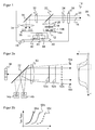
- FIG. 1 shows a schematic sectional view of a sensor 10 according to the invention in a transmission path of the sensor 10 sends a light emitter 12 with two light sources 14a-b, such as LEDs, a transmitted light beam 16, by an example line-shaped aperture 18 and a cylindrical lens 20 on a beam splitter 22 falls.
- the cylindrical lens 20 forms the illuminated diaphragm 18 perpendicular to the plane of the drawing and thereby causes a compression perpendicular to the plane of the drawing.
- the diaphragm 18 is sharply imaged in the transverse direction. In the longitudinal direction, the image is on the one hand intrafokal to ensure a homogeneous illumination of the line, on the other hand as collimated as possible to achieve a high power density.
- the emission lobes of the individual light sources 14a-b still remain visible and overlap only partially. This will be exploited in the distance determination to be described below.
- the transmitted light bundle 16 thus formed in a cross-section into a line passes via a window 26 into a detection area 28 of the sensor 10 in order to illuminate objects to be detected there.
- Receiving light 30 from such an object which may be both remitted transmitted light 16 and ambient light, falls through the window 26, the cylindrical lens 24 and the beam splitter 22 in a receiving path of the sensor 10.
- There are further cylindrical lenses 32, 34 provided in common with the cylindrical lens 24 form an anamorphic receiving optics of a line shaped light receiver 36 having a plurality of photosensitive pixels.
- a mirror 38 provides a folded beam path, so that the overall length of the sensor 10 is shortened. In the reception image, the highest possible energy density is produced with a small focal length in the direction transverse to the line, while the highest possible resolution is achieved in the direction along the line through a large focal length.
- an anamorphic transmitting and receiving optics is to be understood by way of example. More or fewer, different and different lenses and optical elements may be used.
- the folds by beam splitter 22 or mirror 38 are also preferred in order to achieve a compact arrangement. But there are also alternative arrangements without such elements possible. All that is required is a structured illumination with intensity differences, as achieved, for example, by an axial offset of the optical axes of the light sources 14a-b with respect to the optical axis of the sensor 10.
- the light receiver 36 generates a locally resolved receive signal corresponding to its pixels, which is further processed in an evaluation unit 40.
- the evaluation unit 40 also includes the control functionality of the sensor 10 and is also connected to the light transmitter 12. As some elements of the evaluation unit 40 are in FIG. 1 a distance measuring device 42, a scale correction means 44 and a memory 46, the function of which is described immediately in connection with FIG FIG. 2 is explained.
- the information about a detected object, which the evaluation unit 40 finds with the aid of the received signal, is output via an output 48, for example dimensions, edge positions or positions of an object, or even a binary switching signal depending on whether an object with certain properties is currently detected is or not.
- FIG. 2a shows in a schematic sectional view for clarity only a few elements of the sensor 10, namely the light sources 14a-b, the beam splitter 22 and the light receiver 36.
- the transmitting and receiving optics is greatly simplified represented by only a single lens 50.
- the two light sources 14a-b of the integrated illumination of the sensor 10 are arranged or the transmitting optics are designed such that the ratio of the optical intensities or powers of the respective light sources 14a-b detected by the light receiver 36 at least at a specific location on the light receiver 36 changes with the object distance.
- FIG. 2a the transmitted light bundles 16a-b of the two light sources 14a-b individually drawn once with solid and once with dashed lines.
- FIG. 2a are plotted with corresponding line design, ie a dashed line for the first light source 14a and a solid line for the second light source 14b, the intensities I of the light sources 14a-b on an object 52a-c as a function of the position x on the light receiver 36 , In this case, the most collimated transmitted light bundles 16a-b object and receiver overlap only partially.
- the evaluation unit 40 the intensity components of the individual light sources 14a-b separately determine. A corresponding picture emerges when using additional light sources.
- the ratio of the intensities or optical powers of the two light sources changes 14a-b. This results in a different ratio depending on in which object distance an object 52a-c is detected.
- FIG. 2a are three objects 52a-c marked with different line design.
- the intensity ratio in the transition region 54 is in FIG. 2b applied purely schematically and without numerical values on the axes above the position x on the light receiver.
- a different characteristic curve 56a-c is created for different object distances of the objects 52a-c, whose line design in FIG FIG. 2b the associated object 52a-c in FIG. 2a equivalent.
- the distance measuring device 42 now compares the intensity ratio currently recorded in the transition region 54 with the known characteristic curves 56a-c stored in the memory 46 at different object distances and thus finds the suitable characteristic curve 56a-c and the associated object distance. Interpolation also allows object distances between two known characteristic curves 56a-c to be measured.
- the thus measured object distance then uses the magnification unit 44 to rescale the magnification.
- the necessary scaling factors can be stored in the memory 46 together with the characteristic curves 56a-c, for example. Despite the entocentric receiving optics, this distance correction achieves a faithful magnification independently of the object distance.
Landscapes
- Physics & Mathematics (AREA)
- General Physics & Mathematics (AREA)
- Electromagnetism (AREA)
- Engineering & Computer Science (AREA)
- Radar, Positioning & Navigation (AREA)
- Remote Sensing (AREA)
- Length Measuring Devices By Optical Means (AREA)
- Measurement Of Optical Distance (AREA)
Abstract
Description
- Die Erfindung betrifft einen optoelektronischen Sensor mit einem Lichtsender und einem Lichtempfänger zum Abbilden eines Objekts sowie ein Verfahren zum Abbilden eines Objekts mit treuem Abbildungsmaßstab nach dem Oberbegriff von Anspruch 1 beziehungsweise 11.
- Kamerabasierte Sensoren verwenden Bildsensoren mit einer Vielzahl von zu einer Zeile oder Matrix angeordneten Pixeln. Mit Hilfe einer integrierten Beleuchtung wird ein Objektbereich ausgeleuchtet und je nach Sensor und Anwendung ein flächiges zweidimensionales oder ein zeilenförmiges Bild aufgenommen und ausgewertet. Damit werden beispielsweise Objekte oder Kanten erkannt oder ihre Geometrie vermessen.
- Bei Kamerasensoren am verbreitetsten ist die Verwendung entozentrischer Objektive. Wie beim menschlichen Auge ändert sich dabei der Abbildungsmaßstab der Objekte mit deren Objektabstand. Ein fernes Objekt erscheint demnach auf dem Bildsensor kleiner als ein nahes Objekt identischer Abmessung. Möchte man mit einem solchen Kamerasensor Objekte vermessen, so ist deshalb genau darauf zu achten, sie in einem vorgegebenen Abstand, der Nenntastweite, zu halten. Damit sind starke Rahmenbedingungen aufgestellt, welche die Flexibilität von Kamerasensoren in solchen Vermessungsanwendungen erheblich einschränken.
- Es ist bekannt, anstelle eines entozentrischen Objektivs ein objektseitig telezentrisches Objektiv zu verwenden. Dieses hat die Eigenschaft, dass keine perspektivischen Größenunterschiede auftreten, sich der Abbildungsmaßstab also nicht mit dem Objektabstand ändert. Das telezentrische Objektiv sorgt dann für einen Toleranzbereich um die Nenntastweite innerhalb des begrenzten Schärfentiefebereichs. Telezentrische Objektive benötigen aber eine sehr große Baulänge des Sensors und haben nur eine geringe Intensitätsübertragung.
- Die
EP 1 136 787 B1 wählt wegen der genannten Nachteile der telezentrischen Abbildung den Weg, ein entozentrisches Objektiv einzusetzen und in einer nachträglichen Auswertung den Abbildungsmaßstab in Abhängigkeit des Objektabstands zu korrigieren. Dafür muss der Objektabstand gemessen werden. In dem Sensor nachEP 1 136 787 B1 ist deshalb ein zusätzlicher Lichtsender in einem Winkel zum Bildsensor angeordnet, der einen Kompensationslichtstrahl erzeugt, mit dessen Hilfe der Objektabstand trianguliert wird. Der zusätzliche Lichtsender beansprucht aber zusätzlichen Bauraum, der wegen der Triangulationsanordnung zu einem deutlich vergrößerten Sensor führt. - Im Stand der Technik sind außer der in
EP 1 136 787 B1 verwendeten Triangulation verschiedene Verfahren zur Abstandsmessung bekannt. Dazu zählen puls- oder phasenbasierte Lichtlaufzeitverfahren und Lichtschnittverfahren. DieDE 103 01 094 A1 beschreibt eine Vorrichtung zur zweidimensionalen Abstandsmessung mit einer Kamera zur Aufnahme von Bildern. Zur Beleuchtung sind eine primäre und eine sekundäre Lichtquelle vorgesehen, deren Lichtbündel gezielt unterschiedlich gewählt wird, beispielsweise eines divergent und das andere konvergent. Aus Unterschieden der Beleuchtungsintensität bei Beleuchtung mit jeweils nur einer Lichtquelle wird dann auf den Objektabstand geschlossen. Durch die unterschiedlich fokussierten Lichtquellen entstehen nahezu im gesamten Überwachungsbereich unterschiedliche Energiedichten, so dass an allen Orten Abstandsinformationen bestimmt werden können. Die Beleuchtung derDE 103 01 094 A1 erzielt aber nur eine vergleichsweise geringe Energiedichte mit entsprechend geringer Reichweite und hoher Rauschempfindlichkeit. - Es ist daher Aufgabe der Erfindung, einen einfacheren kamerabasierten Sensor mit treuem Abbildungsmaßstab und entozentrischem Objektiv aufzufinden.
- Diese Aufgabe wird durch einen optoelektronischen Sensor mit einem Lichtsender und einem Lichtempfänger zum Abbilden eines Objekts und ein Verfahren zum Abbilden eines Objekts mit treuem Abbildungsmaßstab gemäß Anspruch 1 beziehungsweise Anspruch 11 gelöst. Dabei geht die Lösung von dem Grundgedanken aus, zunächst Bilddaten durch eine entozentrische Empfängeroptik mit abstandsabhängigem Abbildungsmaßstab aufzunehmen und den Abbildungsmaßstab anschließend anhand des gemessenen Objektabstands zu korrigieren. Dabei wird zur Abstandsbestimmung die vorhandene aktive Beleuchtung des Sensors verwendet. Sie erzeugt durch mehrere Lichtquellen eine strukturierte Beleuchtung, und aus den Intensitätsunterschieden bei Beleuchtung mit unterschiedlichen Lichtquellen wird auf den Objektabstand rückgeschlossen.
- Die Erfindung hat den Vorteil, dass keine aufwändige Optik, wie eine telezentrische Optik, notwendig ist. Die ohnehin vorgesehene Beleuchtung dient zugleich der Abstandsmessung. Ein zusätzlicher Kompensationslichtstrahl oder dergleichen ist deshalb nicht mehr erforderlich. Dies führt zu einem vereinfachten und deutlich baukleineren Sensor. Die strukturierte Beleuchtung erzeugt eine hohe Energiedichte gezielt am Erfassungsort der Objekte und damit eine hohe Energieeffizienz und Empfindlichkeit des Sensors.
- Dem Lichtsender ist bevorzugt eine anamorphotische Sendeoptik zur Erzeugung einer Linienbeleuchtung aus dem Licht der Lichtquellen vorgeordnet. Diese Sendeoptik ist demnach eine gemeinsame Sendeoptik für alle Lichtquellen, so dass deren Lichtstrahl in gleicher Weise geformt wird. Eine anamorphotische Optik bildet in der einen Achse anders ab als in der anderen Achse, indem beispielsweise in der einen Achse keine Veränderung und in der anderen Achse eine Stauchung stattfindet. Dadurch entsteht ein langgezogener Lichtfleck, der zusätzlich noch durch eine Schlitzblende zu einer Linie geformt werden kann. Dabei bleiben aber durch die nur teilweise Überlappung der Lichtquellen lokale Intensitätsunterschiede erhalten. Die anamorphotische Optik weist zur Erzeugung einer Linie beispielsweise eine oder mehrere Zylinderlinsen auf. Vorzugsweise wird eine solche Beleuchtung mit einer Zeilenkamera kombiniert, bei der also die Pixel des Lichtempfängers zu einer Zeile oder zumindest einer langgestreckten Matrix angeordnet sind.
- Die Empfängeroptik weist bevorzugt eine anamorphotische Optik auf. Dies ist das Gegenstück zu einer entsprechenden sendeseitigen Optik, um die Objekte auf einen zeilenförmigen Lichtempfänger beziehungsweise Bildsensor abzubilden. Auch die Empfängeroptik lässt sich beispielsweise mit einer oder mehreren Zylinderlinsen realisieren.
- Vorzugsweise ist ein Strahlteiler vorgesehen, so dass zumindest eine Zylinderlinse von Lichtsender und Lichtempfänger gemeinsam nutzbar ist. Der Strahlteiler knickt dabei die optische Achse des Lichtsenders oder des Lichtempfängers, so dass diese beiden optischen Achsen vor dem Strahlteiler in der gemeinsamen optischen Achse des Sensors zusammenfallen. Damit werden optische Elemente in dem gemeinsamen Pfad sowohl sendeseitig als auch empfangsseitig genutzt, während mögliche weitere individuelle Elemente hinter dem Strahlteiler für unterschiedliche optische Eigenschaften im Sende- und Empfangspfad sorgen können.
- Der Empfangskanal ist bevorzugt mittels eines Spiegelelements gefaltet. Damit ist gemeint, dass die optische Achse des Lichtempfängers an dem Spiegelelement geknickt wird, so dass der Lichtempfänger quer zur Hauptachse des Sensors ausgerichtet werden kann und somit eine kürzere Baulänge möglich wird.
- Die optischen Achsen der Lichtquellen sind bevorzugt zu der optischen Achse des Sensors versetzt. Prinzipiell genügt es auch, wenn nur eine der Lichtquellen einen solchen Versatz aufweist. In beiden Fällen sorgt der Versatz für die Intensitätsunterschiede, welche die Abstandsmesseinrichtung zur Bestimmung des Objektabstands auswertet.
- Die Abbildungsmaßstabskorrektureinheit ist bevorzugt dafür ausgebildet, den Abbildungsmaßstab einer Nenntastweite als Referenz zu verwenden und Korrekturen des Abbildungsmaßstabs anhand einer Abweichung zwischen Abstand und Nenntastweite vorzunehmen. Der Sensor ist damit grundsätzlich auf die Nenntastweite eingestellt. Wird ein abweichender Abstand gemessen, so wird eine Korrektur des Abbildungsmaßstabs vorgenommen, etwa durch einen Skalierungsfaktor. Der passende Abbildungsmaßstab zu jedem Abstand steht per Design des Sensors fest und kann somit beispielsweise berechnet, ab Werk festgelegt oder vor dem Betrieb eingelernt und in einem Speicher des Sensors abgelegt werden.
- Die Abstandsmesseinrichtung ist bevorzugt dafür ausgebildet, die jeweilige Intensität des Beleuchtungsbereichs bei zeitversetzter Aktivierung jeweils einer Lichtquelle zu bestimmen. Dadurch wird auf einfache Weise festgestellt, welcher Anteil der ortsabhängigen Intensitätsverteilung auf welche Lichtquelle zurückzuführen ist.
- Vorzugsweise ist die Abstandsmesseinrichtung dafür ausgebildet, den Abstand aus dem Quotienten der Beleuchtungsintensität der ersten Lichtquelle und der Beleuchtungsintensität der zweiten Lichtquelle zu bestimmen. Dieser Quotient kann dabei für jedes Pixel des Lichtempfängers gebildet werden und bildet dann eine Messkurve, die charakteristisch für einen bestimmten Objektabstand ist.
- In der Abstandsmesseinrichtung sind bevorzugt Kennlinien des Quotienten über dem Ort auf dem Lichtempfänger für verschiedene Objektabstände gespeichert, und die Abstandsbestimmung erfolgt anhand eines Vergleichs der Kennlinien und des gemessenen Quotienten. Die im vorigen Absatz genannte Messkurve wird somit mit bekannten Kennlinien verglichen und dann dem passenden Objektabstand zugeordnet. Durch Interpolation wird dabei erforderlichenfalls auch eine höhere Auflösung erzielt als durch die Anzahl der gespeicherten Kennlinien vorgegeben.
- Der Vergleich ist besonders bevorzugt auf einen Übergangsbereich des Lichtempfängers beschränkt, in dem die Intensität zumindest einer Lichtquelle abfällt. Der Übergangsbereich liegt üblicherweise am Rande des Beleuchtungsbereichs von einer der Lichtquellen. Dort sind dann die Intensitätsunterschiede besonders hoch, so dass mit nur vergleichsweise wenigen Datenpunkten der Abstand genau bestimmbar ist.
- Das erfindungsgemäße Verfahren kann auf ähnliche Weise weitergebildet werden und zeigt dabei ähnliche Vorteile. Derartige vorteilhafte Merkmale sind beispielhaft, aber nicht abschließend in den sich an die unabhängigen Ansprüche anschließenden Unteransprüchen beschrieben.
- Die Erfindung wird nachstehend auch hinsichtlich weiterer Merkmale und Vorteile beispielhaft anhand von Ausführungsformen und unter Bezug auf die beigefügte Zeichnung näher erläutert. Die Abbildungen der Zeichnung zeigen in:
- Fig. 1
- eine schematische Schnittdarstellung eines erfindungsgemäßen Sensors;
- Fig. 2a
- eine vereinfachte Darstellung von Lichtsender, Lichtempfänger und Optik des Sensors gemäß
Figur 1 zur Erläuterung des Strahlengangs; und - Fig. 2b
- eine schematische Darstellung des in Abhängigkeit vom Ort auf dem Lichtempfänger aufgetragenen Intensitätsquotienten der beiden Lichtquellen auf einem angetasteten Objekt in verschiedenen Objektabständen.
-
Figur 1 zeigt eine schematische Schnittdarstellung eines erfindungsgemäßen Sensors 10. In einem Sendepfad des Sensors 10 sendet ein Lichtsender 12 mit zwei Lichtquellen 14a-b, beispielsweise LEDs, ein Sendelichtbündel 16 aus, das durch eine beispielsweise zeilenförmige Blende 18 und eine Zylinderlinse 20 auf einen Strahlteiler 22 fällt. Dabei bildet die Zylinderlinse 20 die ausgeleuchtete Blende 18 senkrecht zur Zeichenebene ab und bewirkt dabei eine Stauchung senkrecht zur Zeichenebene. - Nach der Umlenkung erfolgt in einer zweiten Zylinderlinse 24 eine weitere Stauchung des Sendelichtbündels 16 in der Zeichnungsebene und eine Spreizung in Vertikalrichtung. Die Sendeoptik aus der Blende 18 und den beiden Zylinderlinsen 20, 24 sorgt somit für einen langgestreckten, weitgehend linienförmigen Lichtfleck.
- Damit entsteht eine anamorphotische Sendeoptik. Die Blende 18 wird in Querrichtung scharf abgebildet. In Längsrichtung erfolgt die Abbildung einerseits intrafokal, um eine homogene Ausleuchtung der Zeile zu gewährleisten, andererseits so kollimiert wie möglich, um eine hohe Leistungsdichte zu erreichen. Dabei bleiben jedoch die Sendekeulen der einzelnen Lichtquellen 14a-b noch zu erkennen und überlappen sich nur zum Teil. Dies wird in der weiter unten noch zu beschreibenden Abstandsbestimmung ausgenutzt.
- Das somit im Querschnitt zu einer Linie geformte Sendelichtbündel 16 gelangt über ein Fenster 26 in einen Erfassungsbereich 28 des Sensors 10, um dort zu erfassende Objekte zu beleuchten. Empfangslicht 30 von einem solchen Objekt, das sowohl remittiertes Sendelicht 16 als auch Umgebungslicht sein kann, fällt durch das Fenster 26, die Zylinderlinse 24 und den Strahlteiler 22 in einen Empfangspfad des Sensors 10. Dort sind weitere Zylinderlinsen 32, 34 vorgesehen, die gemeinsam mit der Zylinderlinse 24 eine anamorphotische Empfangsoptik eines zeilenförmigen Lichtempfängers 36 mit einer Vielzahl von lichtempfindlichen Pixeln bilden. Ein Spiegel 38 sorgt für einen gefalteten Strahlengang, so dass die Baulänge des Sensors 10 verkürzt wird. Bei der Empfangsabbildung wird mit einer kleinen Brennweite in Richtung quer zu der Zeile eine möglichst hohe Energiedichte erzeugt, während in Richtung längs der Zeile durch eine große Brennweite eine möglichst hochauflösende Abbildung erzielt wird.
- Die in
Figur 1 gezeigte konkrete Ausführung einer anamorphotischen Sende- und Empfangsoptik ist beispielhaft zu verstehen. Es können mehr oder weniger, andersartige und anders angeordnete Linsen und optische Elemente verwendet werden. Auch die Faltungen durch Strahlteiler 22 oder Spiegel 38 sind lediglich bevorzugt, um eine kompakte Anordnung zu erreichen. Es sind aber auch alternative Anordnungen ohne derartige Elemente möglich. Erforderlich ist lediglich eine strukturierte Beleuchtung mit Intensitätsunterschieden, wie sie beispielsweise durch einen axialen Versatz der optischen Achsen der Lichtquellen 14a-b gegenüber der optischen Achse des Sensors 10 erreicht werden. - Der Lichtempfänger 36 erzeugt ein entsprechend seiner Pixel ortsaufgelöstes Empfangssignal, welches in einer Auswertungseinheit 40 weiterverarbeitet wird. Die Auswertungseinheit 40 umfasst zugleich die Steuerungsfunktionalität des Sensors 10 und ist auch mit dem Lichtsender 12 verbunden. Als einige Elemente der Auswertungseinheit 40 sind in
Figur 1 eine Abstandsmesseinrichtung 42, eine Abbildungsmaßstabkorrektureinrichtung 44 und ein Speicher 46 gezeigt, deren Funktion sogleich im Zusammenhang mitFigur 2 erläutert wird. Die Informationen über ein erfasstes Objekt, welche die Auswertungseinheit 40 mit Hilfe des Empfangssignal auffindet, werden über einen Ausgang 48 ausgegeben, beispielsweise Abmessungen, Kantenlagen oder Positionen eines Objekts, oder auch ein binäres Schaltsignal in Abhängigkeit davon, ob gegenwärtig ein Objekt mit bestimmten Eigenschaften erfasst ist oder nicht. -
Figur 2a zeigt in einer schematischen Schnittdarstellung zur besseren Übersicht nur einige Elemente des Sensors 10, nämlich die Lichtquellen 14a-b, den Strahlteiler 22 und den Lichtempfänger 36. Die Sende- und Empfangsoptik wird stark vereinfacht durch nur eine einzige Linse 50 repräsentiert. Die beiden Lichtquellen 14a-b der integrierten Beleuchtung des Sensors 10 sind so angeordnet beziehungsweise die Sendeoptik so ausgebildet, dass sich das Verhältnis der von dem Lichtempfänger 36 detektierten optischen Intensitäten oder Leistungen der jeweiligen Lichtquellen 14a-b zumindest an einer bestimmten Stelle auf dem Lichtempfänger 36 mit dem Objektabstand ändert. - Dazu sind in
Figur 2a die Sendelichtbündel 16a-b der beiden Lichtquellen 14a-b einzeln einmal mit durchgezogenen und einmal mit gestrichelten Linien eingezeichnet. Ganz rechts inFigur 2a sind mit entsprechender Liniengestaltung, also einer gestrichelten Linie für den die erste Lichtquelle 14a und einer durchgezogenen Linie für die zweite Lichtquelle 14b, die Intensitäten I der Lichtquellen 14a-b auf einem Objekt 52a-c in Abhängigkeit von der Lage x auf dem Lichtempfänger 36 aufgetragen. Dabei überlappen sich die möglichst kollimierten Sendelichtbündel 16a-b objekt- wie empfängerseitig nur teilweise. Durch zeitversetzte Ansteuerung der Lichtquellen 14a-b kann die Auswertungseinheit 40 die Intensitätsanteile der einzelnen Lichtquellen 14a-b gesondert bestimmen. Ein ganz entsprechendes Bild ergibt sich bei der Verwendung zusätzlicher Lichtquellen. - Vor allem in einem Übergangsbereich 54 am Rand des Beleuchtungsbereichs von einer der Lichtquellen 14a-b, wo sich in der einen Richtung die Sendelichtbündel 16a-b überlappen und in der anderen Richtung nicht mehr, ändert sich das Verhältnis der Intensitäten oder optischen Leistungen der beiden Lichtquellen 14a-b. Dabei ergibt sich ein unterschiedliches Verhältnis je nachdem, in welchem Objektabstand ein Objekt 52a-c erfasst wird. In
Figur 2a sind drei Objekte 52a-c mit unterschiedlicher Liniengestaltung eingezeichnet. - Das Intensitätsverhältnis in dem Übergangsbereich 54 ist in
Figur 2b rein schematisch und ohne Zahlenwerte an den Achsen über der Lage x auf dem Lichtempfänger aufgetragen. Dabei entsteht für unterschiedliche Objektabstände der Objekte 52a-c jeweils eine eigene Kennlinie 56a-c, deren Liniengestaltung inFigur 2b dem zugehörigen Objekt 52a-c inFigur 2a entspricht. - Die Abstandsmesseinrichtung 42 vergleicht nun das aktuell in dem Übergangsbereich 54 erfasste Intensitätsverhältnis mit den im Speicher 46 abgelegten bekannten Kennlinien 56a-c zu verschiedenen Objektabständen und findet auf diese Weise die passende Kennlinie 56a-c und den dazugehörigen Objektabstand. Durch Interpolation können auch Objektabstände zwischen zwei bekannten Kennlinien 56a-c gemessen werden.
- Den somit gemessenen Objektabstand verwendet dann die Abbildungsmaßstabkorrektureinheit 44, um den Abbildungsmaßstab zu reskalieren. Die notwendigen Skalierungsfaktoren können beispielsweise gemeinsam mit den Kennlinien 56a-c in dem Speicher 46 abgelegt sein. Durch diese Abstandskorrektur wird trotz entozentrischer Empfangsoptik ein treuer Abbildungsmaßstab unabhängig vom Objektabstand erreicht.
Claims (11)
- Optoelektronischer Sensor (10) mit einem Lichtsender (12) und einem Lichtempfänger (36) zum Abbilden eines Objekts (52), der eine Vielzahl zu einer Zeile oder einer Matrix angeordnete Pixel aufweist und dem eine entozentrische Empfängeroptik (24, 32, 34) vorgeordnet ist, wobei eine Abstandsmesseinrichtung (42) für die Bestimmung eines Abstands zwischen Sensor (10) und Objekt (52) und eine Abbildungsmaßstabskorrektureinheit (44) vorgesehen ist, mittels derer der Abbildungsmaßstab des Objekts (52) in Abhängigkeit des Abstands korrigierbar ist,
dadurch gekennzeichnet,
dass der Lichtsender (12) mindestens eine erste Lichtquelle (14a) und eine zweite Lichtquelle (14b) aufweist, deren Beleuchtungsbereiche teilweise überlappen, so dass auf dem Objekt (52) ein gemeinsamer Beleuchtungsbereich mit ortsabhängigen Intensitätsunterschieden entsteht, und dass die Abstandsmesseinrichtung (42) dafür ausgebildet ist, den Abstand aus den Intensitätsunterschieden zu bestimmen. - Sensor (10) nach Anspruch 1,
wobei dem Lichtsender (12) eine anamorphotische Sendeoptik (20, 24), insbesondere mit einer oder mehreren Zylinderlinsen, zur Erzeugung einer Linienbeleuchtung aus dem Licht (16) der Lichtquellen (14) vorgeordnet ist. - Sensor (10) nach einem der vorhergehenden Ansprüche,
wobei die Empfängeroptik (24, 32, 34) eine anamorphotische Optik aufweist, insbesondere mit einer oder mehreren Zylinderlinsen. - Sensor (10) nach Anspruch 2 und 3,
wobei ein Strahlteiler (22) vorgesehen ist, so dass zumindest eine Zylinderlinse (24) von Lichtsender (12) und Lichtempfänger (36) gemeinsam nutzbar ist. - Sensor (10) nach einem der vorhergehenden Ansprüche,
wobei der Empfangskanal mittels eines Spiegelelements (38) gefaltet ist. - Sensor (10) nach einem der vorhergehenden Ansprüche,
wobei die optischen Achsen der Lichtquellen (14a-b) zu der optischen Achse des Sensors (10) versetzt sind. - Sensor (10) nach einem der vorhergehenden Ansprüche,
wobei die Abbildungsmaßstabskorrektureinheit (44) dafür ausgebildet ist, den Abbildungsmaßstab einer Nenntastweise als Referenz zu verwenden und Korrekturen des Abbildungsmaßstabs anhand einer Abweichung zwischen Abstand und Nenntastweite vorzunehmen, wobei die Korrekturen insbesondere in einem Speicher (46) abgelegt und/oder vor dem Messbetrieb eingelernt sind. - Sensor (10) nach einem der vorhergehenden Ansprüche,
wobei die Abstandsmesseinrichtung (42) dafür ausgebildet ist, die jeweilige Intensität des Beleuchtungsbereichs bei zeitversetzter Aktivierung jeweils einer Lichtquelle (14a-b) zu bestimmen. - Sensor (10) nach einem der vorhergehenden Ansprüche,
wobei die Abstandsmesseinrichtung (42) dafür ausgebildet ist, den Abstand aus dem Quotienten der Beleuchtungsintensität der ersten Lichtquelle (14a) und der Beleuchtungsintensität der zweiten Lichtquelle (14b) zu bestimmen. - Sensor (10) nach einem der vorhergehenden Ansprüche,
wobei in der Abstandsmesseinrichtung (42) Kennlinien (56) des Quotienten über dem Ort auf dem Lichtempfänger (36) für verschiedene Objektabstände gespeichert sind und die Abstandsbestimmung anhand eines Vergleichs der Kennlinien (56) und des gemessenen Quotienten erfolgt, wobei der Vergleich insbesondere auf einen Übergangsbereich (54) des Lichtempfängers (36) beschränkt ist, in dem die Intensität zumindest einer Lichtquelle (14a-b) abfällt. - Verfahren zum Abbilden eines Objekts (52) mit treuem Abbildungsmaßstab, wobei das Objekt beleuchtet und auf einem Lichtempfänger mit einer Vielzahl zu einer Zeile oder einer Matrix angeordneter Pixel durch eine entozentrische Empfängeroptik (24, 32, 34) abgebildet, der Abstand zu dem Objekt (52) bestimmt und der Abbildungsmaßstab des Objekts (52) in Abhängigkeit des Abstands korrigiert wird,
dadurch gekennzeichnet,
dass das Objekt von mindestens einer ersten Lichtquelle (14a) und einer zweiten Lichtquelle (14b) beleuchtet wird, deren Beleuchtungsbereiche teilweise überlappen, so dass auf dem Objekt (52) ein gemeinsamer Beleuchtungsbereich mit ortsabhängigen Intensitätsunterschieden entsteht, und dass der Abstand aus den Intensitätsunterschieden bestimmt wird.
Applications Claiming Priority (1)
| Application Number | Priority Date | Filing Date | Title |
|---|---|---|---|
| DE202011001808U DE202011001808U1 (de) | 2011-01-22 | 2011-01-22 | Optoelektronischer Sensor |
Publications (2)
| Publication Number | Publication Date |
|---|---|
| EP2479534A1 true EP2479534A1 (de) | 2012-07-25 |
| EP2479534B1 EP2479534B1 (de) | 2012-12-12 |
Family
ID=44759599
Family Applications (1)
| Application Number | Title | Priority Date | Filing Date |
|---|---|---|---|
| EP20110184688 Not-in-force EP2479534B1 (de) | 2011-01-22 | 2011-10-11 | Optoelektronischer Sensor |
Country Status (3)
| Country | Link |
|---|---|
| EP (1) | EP2479534B1 (de) |
| DE (1) | DE202011001808U1 (de) |
| ES (1) | ES2399204T3 (de) |
Families Citing this family (3)
| Publication number | Priority date | Publication date | Assignee | Title |
|---|---|---|---|---|
| DE102022125115B4 (de) | 2022-09-29 | 2025-08-14 | Jenoptik Industrial Metrology Germany Gmbh | Optische Messverfahren und optische Messvorrichtungen |
| DE102024128982A1 (de) * | 2024-10-08 | 2026-04-09 | Sick Ag | Reflexions-Lichttaster |
| DE102024210526A1 (de) * | 2024-10-31 | 2026-04-30 | Fraunhofer-Gesellschaft zur Förderung der angewandten Forschung eingetragener Verein | Projektionseinheit zur Abstandsermittlung |
Citations (4)
| Publication number | Priority date | Publication date | Assignee | Title |
|---|---|---|---|---|
| EP0419082A2 (de) * | 1989-09-21 | 1991-03-27 | Stanley Electric Corporation | Gerät zur optischen Abstandmessung |
| DE4238891A1 (de) * | 1992-11-19 | 1994-05-26 | Optimess Ges Fuer Optoelektron | Kamerasystem mit integrierter Entfernungsmeßeinrichtung |
| EP1136787A1 (de) * | 2000-03-24 | 2001-09-26 | Sick AG | Objektabbildung mit Abstandskompensation ( Grösse, Farbe ) |
| DE10301094A1 (de) | 2003-01-14 | 2004-07-22 | Sick Ag | Vorrichtung zur zweidimensionalen Abstandsmessung |
Family Cites Families (9)
| Publication number | Priority date | Publication date | Assignee | Title |
|---|---|---|---|---|
| US5610719A (en) * | 1995-07-10 | 1997-03-11 | Qc Optics, Inc. | Displacement detection system |
| DE19840049C5 (de) * | 1998-09-02 | 2007-11-08 | Leica Geosystems Ag | Vorrichtung zur optischen Distanzmessung |
| DE19853302A1 (de) * | 1998-11-19 | 2000-05-25 | Waelde Juergen | Optischer Abstandsmesser |
| US6124924A (en) * | 1998-12-24 | 2000-09-26 | Applied Materials, Inc. | Focus error correction method and apparatus |
| JP3945120B2 (ja) * | 2000-03-31 | 2007-07-18 | 松下電工株式会社 | 測距センサ及びその調整方法 |
| EP1258766A3 (de) * | 2001-05-14 | 2004-09-22 | Robert Bosch Gmbh | Optische Messvorrichtung zur Formvermessung |
| US20030058455A1 (en) * | 2001-09-14 | 2003-03-27 | Akimitsu Ebihara | Three-dimensional shape measuring apparatus |
| JP4188795B2 (ja) * | 2003-10-07 | 2008-11-26 | リコー光学株式会社 | 光パワー合成用光学系および光源モジュール |
| DE202007002260U1 (de) * | 2007-02-15 | 2008-06-26 | Leuze Electronic Gmbh & Co Kg | Optoelektronische Vorrichtung |
-
2011
- 2011-01-22 DE DE202011001808U patent/DE202011001808U1/de not_active Expired - Lifetime
- 2011-10-11 ES ES11184688T patent/ES2399204T3/es active Active
- 2011-10-11 EP EP20110184688 patent/EP2479534B1/de not_active Not-in-force
Patent Citations (5)
| Publication number | Priority date | Publication date | Assignee | Title |
|---|---|---|---|---|
| EP0419082A2 (de) * | 1989-09-21 | 1991-03-27 | Stanley Electric Corporation | Gerät zur optischen Abstandmessung |
| DE4238891A1 (de) * | 1992-11-19 | 1994-05-26 | Optimess Ges Fuer Optoelektron | Kamerasystem mit integrierter Entfernungsmeßeinrichtung |
| EP1136787A1 (de) * | 2000-03-24 | 2001-09-26 | Sick AG | Objektabbildung mit Abstandskompensation ( Grösse, Farbe ) |
| EP1136787B1 (de) | 2000-03-24 | 2005-01-19 | Sick AG | Objektabbildung mit Abstandskompensation ( Grösse, Farbe ) |
| DE10301094A1 (de) | 2003-01-14 | 2004-07-22 | Sick Ag | Vorrichtung zur zweidimensionalen Abstandsmessung |
Also Published As
| Publication number | Publication date |
|---|---|
| ES2399204T3 (es) | 2013-03-26 |
| DE202011001808U1 (de) | 2012-04-27 |
| EP2479534B1 (de) | 2012-12-12 |
Similar Documents
| Publication | Publication Date | Title |
|---|---|---|
| EP3729137B1 (de) | Multipuls-lidarsystem zur mehrdimensionalen erfassung von objekten | |
| EP1953504B1 (de) | Verfahren zur Erfassung eines Gegenstands und optoelektronische Vorrichtung | |
| EP1821120B1 (de) | Optoelektronische Vorrichtung und Verfahren zu deren Betrieb | |
| CH661987A5 (de) | Einrichtung mit wenigstens einer optischen faser zum wahlweisen positionieren des endes derselben sowie informationsaustauscheinheit mit einer solchen einrichtung. | |
| DE10217294A1 (de) | Sensorausrichtung | |
| DE102009047303A1 (de) | Einrichtung für die Kalibrierung eines Sensors | |
| EP2629050A1 (de) | Triangulationslichttaster | |
| WO2019110206A1 (de) | Lidar-system zur umfelderfassung und verfahren zum betreiben eines lidar-systems | |
| DE69803044T2 (de) | Optisches gerät zur kontaktlosen messung des abstandes zu einer lichtquelle | |
| EP1931133A1 (de) | Verfahren und Vorrichtung zur optischen Erfassung einer Struktur | |
| EP2479534B1 (de) | Optoelektronischer Sensor | |
| DE102006034926A1 (de) | Entfernungsmessgerät | |
| EP1617257A1 (de) | Beleuchtungsvorrichtung für ein Lichtrastermikroskop mit Einheit zur Transformation der Beleuchtungsintensitätsverteilung | |
| DE102017101791B4 (de) | Optoelektronische Sensoreinrichtung für ein Kraftfahrzeug und Kraftfahrzeug | |
| WO2017005653A1 (de) | Detektoreinheit für eine optische sensorvorrichtung | |
| DE102009045553B4 (de) | Lichtlaufzeit-Messsystem | |
| EP1672404A1 (de) | Beleuchtungsvorrichtung für ein Lichtrastermikroskop mit linienförmiger Abtastung und ihre Verwendung | |
| DE102018219481A1 (de) | Baugruppe für einen LiDAR-Sensor und LiDAR-Sensor | |
| EP1617272A1 (de) | Beleuchtungsvorrichtung für ein Lichtrastermikroskop mit Einheit zur Transformation der Beleuchtungsintensitätsverteilung | |
| EP4045931A1 (de) | Multipuls-lidarsystem und verfahren zur erfassung eines objekts in einem beobachtungsbereich | |
| DE102019110329A1 (de) | Lichtlaufzeitkamera | |
| DE102022124438B3 (de) | Optoelektronischer sensor | |
| DE10026625C1 (de) | Triangulations-Sensor | |
| DE102005043064B4 (de) | Verfahren zum Messen des Abstandes eines Objektes | |
| EP3547664B1 (de) | Verfahren und sensor zum erzeugen von 3d-bilddaten |
Legal Events
| Date | Code | Title | Description |
|---|---|---|---|
| PUAI | Public reference made under article 153(3) epc to a published international application that has entered the european phase |
Free format text: ORIGINAL CODE: 0009012 |
|
| 17P | Request for examination filed |
Effective date: 20120329 |
|
| AK | Designated contracting states |
Kind code of ref document: A1 Designated state(s): AL AT BE BG CH CY CZ DE DK EE ES FI FR GB GR HR HU IE IS IT LI LT LU LV MC MK MT NL NO PL PT RO RS SE SI SK SM TR |
|
| AX | Request for extension of the european patent |
Extension state: BA ME |
|
| GRAP | Despatch of communication of intention to grant a patent |
Free format text: ORIGINAL CODE: EPIDOSNIGR1 |
|
| GRAS | Grant fee paid |
Free format text: ORIGINAL CODE: EPIDOSNIGR3 |
|
| GRAA | (expected) grant |
Free format text: ORIGINAL CODE: 0009210 |
|
| AK | Designated contracting states |
Kind code of ref document: B1 Designated state(s): AL AT BE BG CH CY CZ DE DK EE ES FI FR GB GR HR HU IE IS IT LI LT LU LV MC MK MT NL NO PL PT RO RS SE SI SK SM TR |
|
| REG | Reference to a national code |
Ref country code: GB Ref legal event code: FG4D Free format text: NOT ENGLISH |
|
| REG | Reference to a national code |
Ref country code: CH Ref legal event code: EP |
|
| REG | Reference to a national code |
Ref country code: AT Ref legal event code: REF Ref document number: 588521 Country of ref document: AT Kind code of ref document: T Effective date: 20121215 |
|
| REG | Reference to a national code |
Ref country code: IE Ref legal event code: FG4D Free format text: LANGUAGE OF EP DOCUMENT: GERMAN |
|
| REG | Reference to a national code |
Ref country code: SE Ref legal event code: TRGR |
|
| REG | Reference to a national code |
Ref country code: DE Ref legal event code: R096 Ref document number: 502011000274 Country of ref document: DE Effective date: 20130207 |
|
| REG | Reference to a national code |
Ref country code: ES Ref legal event code: FG2A Ref document number: 2399204 Country of ref document: ES Kind code of ref document: T3 Effective date: 20130326 |
|
| PG25 | Lapsed in a contracting state [announced via postgrant information from national office to epo] |
Ref country code: FI Free format text: LAPSE BECAUSE OF FAILURE TO SUBMIT A TRANSLATION OF THE DESCRIPTION OR TO PAY THE FEE WITHIN THE PRESCRIBED TIME-LIMIT Effective date: 20121212 Ref country code: LT Free format text: LAPSE BECAUSE OF FAILURE TO SUBMIT A TRANSLATION OF THE DESCRIPTION OR TO PAY THE FEE WITHIN THE PRESCRIBED TIME-LIMIT Effective date: 20121212 Ref country code: NO Free format text: LAPSE BECAUSE OF FAILURE TO SUBMIT A TRANSLATION OF THE DESCRIPTION OR TO PAY THE FEE WITHIN THE PRESCRIBED TIME-LIMIT Effective date: 20130312 |
|
| REG | Reference to a national code |
Ref country code: NL Ref legal event code: VDEP Effective date: 20121212 |
|
| REG | Reference to a national code |
Ref country code: LT Ref legal event code: MG4D |
|
| PG25 | Lapsed in a contracting state [announced via postgrant information from national office to epo] |
Ref country code: GR Free format text: LAPSE BECAUSE OF FAILURE TO SUBMIT A TRANSLATION OF THE DESCRIPTION OR TO PAY THE FEE WITHIN THE PRESCRIBED TIME-LIMIT Effective date: 20130313 Ref country code: SI Free format text: LAPSE BECAUSE OF FAILURE TO SUBMIT A TRANSLATION OF THE DESCRIPTION OR TO PAY THE FEE WITHIN THE PRESCRIBED TIME-LIMIT Effective date: 20121212 Ref country code: LV Free format text: LAPSE BECAUSE OF FAILURE TO SUBMIT A TRANSLATION OF THE DESCRIPTION OR TO PAY THE FEE WITHIN THE PRESCRIBED TIME-LIMIT Effective date: 20121212 |
|
| PG25 | Lapsed in a contracting state [announced via postgrant information from national office to epo] |
Ref country code: EE Free format text: LAPSE BECAUSE OF FAILURE TO SUBMIT A TRANSLATION OF THE DESCRIPTION OR TO PAY THE FEE WITHIN THE PRESCRIBED TIME-LIMIT Effective date: 20121212 Ref country code: IS Free format text: LAPSE BECAUSE OF FAILURE TO SUBMIT A TRANSLATION OF THE DESCRIPTION OR TO PAY THE FEE WITHIN THE PRESCRIBED TIME-LIMIT Effective date: 20130412 Ref country code: RS Free format text: LAPSE BECAUSE OF FAILURE TO SUBMIT A TRANSLATION OF THE DESCRIPTION OR TO PAY THE FEE WITHIN THE PRESCRIBED TIME-LIMIT Effective date: 20121212 Ref country code: BG Free format text: LAPSE BECAUSE OF FAILURE TO SUBMIT A TRANSLATION OF THE DESCRIPTION OR TO PAY THE FEE WITHIN THE PRESCRIBED TIME-LIMIT Effective date: 20130312 Ref country code: CZ Free format text: LAPSE BECAUSE OF FAILURE TO SUBMIT A TRANSLATION OF THE DESCRIPTION OR TO PAY THE FEE WITHIN THE PRESCRIBED TIME-LIMIT Effective date: 20121212 Ref country code: SK Free format text: LAPSE BECAUSE OF FAILURE TO SUBMIT A TRANSLATION OF THE DESCRIPTION OR TO PAY THE FEE WITHIN THE PRESCRIBED TIME-LIMIT Effective date: 20121212 |
|
| PG25 | Lapsed in a contracting state [announced via postgrant information from national office to epo] |
Ref country code: RO Free format text: LAPSE BECAUSE OF FAILURE TO SUBMIT A TRANSLATION OF THE DESCRIPTION OR TO PAY THE FEE WITHIN THE PRESCRIBED TIME-LIMIT Effective date: 20121212 Ref country code: PT Free format text: LAPSE BECAUSE OF FAILURE TO SUBMIT A TRANSLATION OF THE DESCRIPTION OR TO PAY THE FEE WITHIN THE PRESCRIBED TIME-LIMIT Effective date: 20130412 Ref country code: NL Free format text: LAPSE BECAUSE OF FAILURE TO SUBMIT A TRANSLATION OF THE DESCRIPTION OR TO PAY THE FEE WITHIN THE PRESCRIBED TIME-LIMIT Effective date: 20121212 Ref country code: PL Free format text: LAPSE BECAUSE OF FAILURE TO SUBMIT A TRANSLATION OF THE DESCRIPTION OR TO PAY THE FEE WITHIN THE PRESCRIBED TIME-LIMIT Effective date: 20121212 |
|
| PLBE | No opposition filed within time limit |
Free format text: ORIGINAL CODE: 0009261 |
|
| STAA | Information on the status of an ep patent application or granted ep patent |
Free format text: STATUS: NO OPPOSITION FILED WITHIN TIME LIMIT |
|
| PG25 | Lapsed in a contracting state [announced via postgrant information from national office to epo] |
Ref country code: DK Free format text: LAPSE BECAUSE OF FAILURE TO SUBMIT A TRANSLATION OF THE DESCRIPTION OR TO PAY THE FEE WITHIN THE PRESCRIBED TIME-LIMIT Effective date: 20121212 |
|
| 26N | No opposition filed |
Effective date: 20130913 |
|
| PG25 | Lapsed in a contracting state [announced via postgrant information from national office to epo] |
Ref country code: CY Free format text: LAPSE BECAUSE OF FAILURE TO SUBMIT A TRANSLATION OF THE DESCRIPTION OR TO PAY THE FEE WITHIN THE PRESCRIBED TIME-LIMIT Effective date: 20121212 Ref country code: HR Free format text: LAPSE BECAUSE OF FAILURE TO SUBMIT A TRANSLATION OF THE DESCRIPTION OR TO PAY THE FEE WITHIN THE PRESCRIBED TIME-LIMIT Effective date: 20121212 |
|
| REG | Reference to a national code |
Ref country code: DE Ref legal event code: R097 Ref document number: 502011000274 Country of ref document: DE Effective date: 20130913 |
|
| BERE | Be: lapsed |
Owner name: SICK A.G. Effective date: 20131031 |
|
| PG25 | Lapsed in a contracting state [announced via postgrant information from national office to epo] |
Ref country code: MC Free format text: LAPSE BECAUSE OF FAILURE TO SUBMIT A TRANSLATION OF THE DESCRIPTION OR TO PAY THE FEE WITHIN THE PRESCRIBED TIME-LIMIT Effective date: 20121212 |
|
| REG | Reference to a national code |
Ref country code: IE Ref legal event code: MM4A |
|
| PG25 | Lapsed in a contracting state [announced via postgrant information from national office to epo] |
Ref country code: BE Free format text: LAPSE BECAUSE OF NON-PAYMENT OF DUE FEES Effective date: 20131031 |
|
| PG25 | Lapsed in a contracting state [announced via postgrant information from national office to epo] |
Ref country code: IE Free format text: LAPSE BECAUSE OF NON-PAYMENT OF DUE FEES Effective date: 20131011 |
|
| PG25 | Lapsed in a contracting state [announced via postgrant information from national office to epo] |
Ref country code: SM Free format text: LAPSE BECAUSE OF FAILURE TO SUBMIT A TRANSLATION OF THE DESCRIPTION OR TO PAY THE FEE WITHIN THE PRESCRIBED TIME-LIMIT Effective date: 20121212 |
|
| REG | Reference to a national code |
Ref country code: CH Ref legal event code: PL |
|
| PG25 | Lapsed in a contracting state [announced via postgrant information from national office to epo] |
Ref country code: LU Free format text: LAPSE BECAUSE OF NON-PAYMENT OF DUE FEES Effective date: 20131011 Ref country code: HU Free format text: LAPSE BECAUSE OF FAILURE TO SUBMIT A TRANSLATION OF THE DESCRIPTION OR TO PAY THE FEE WITHIN THE PRESCRIBED TIME-LIMIT; INVALID AB INITIO Effective date: 20111011 Ref country code: MK Free format text: LAPSE BECAUSE OF FAILURE TO SUBMIT A TRANSLATION OF THE DESCRIPTION OR TO PAY THE FEE WITHIN THE PRESCRIBED TIME-LIMIT Effective date: 20121212 Ref country code: LI Free format text: LAPSE BECAUSE OF NON-PAYMENT OF DUE FEES Effective date: 20141031 Ref country code: CH Free format text: LAPSE BECAUSE OF NON-PAYMENT OF DUE FEES Effective date: 20141031 |
|
| PG25 | Lapsed in a contracting state [announced via postgrant information from national office to epo] |
Ref country code: MT Free format text: LAPSE BECAUSE OF FAILURE TO SUBMIT A TRANSLATION OF THE DESCRIPTION OR TO PAY THE FEE WITHIN THE PRESCRIBED TIME-LIMIT Effective date: 20121212 |
|
| REG | Reference to a national code |
Ref country code: FR Ref legal event code: PLFP Year of fee payment: 5 |
|
| PG25 | Lapsed in a contracting state [announced via postgrant information from national office to epo] |
Ref country code: TR Free format text: LAPSE BECAUSE OF FAILURE TO SUBMIT A TRANSLATION OF THE DESCRIPTION OR TO PAY THE FEE WITHIN THE PRESCRIBED TIME-LIMIT Effective date: 20121212 |
|
| REG | Reference to a national code |
Ref country code: FR Ref legal event code: PLFP Year of fee payment: 6 |
|
| REG | Reference to a national code |
Ref country code: FR Ref legal event code: PLFP Year of fee payment: 7 |
|
| REG | Reference to a national code |
Ref country code: AT Ref legal event code: MM01 Ref document number: 588521 Country of ref document: AT Kind code of ref document: T Effective date: 20161011 |
|
| PG25 | Lapsed in a contracting state [announced via postgrant information from national office to epo] |
Ref country code: AT Free format text: LAPSE BECAUSE OF NON-PAYMENT OF DUE FEES Effective date: 20161011 |
|
| REG | Reference to a national code |
Ref country code: FR Ref legal event code: PLFP Year of fee payment: 8 |
|
| PG25 | Lapsed in a contracting state [announced via postgrant information from national office to epo] |
Ref country code: AL Free format text: LAPSE BECAUSE OF FAILURE TO SUBMIT A TRANSLATION OF THE DESCRIPTION OR TO PAY THE FEE WITHIN THE PRESCRIBED TIME-LIMIT Effective date: 20121212 |
|
| PGFP | Annual fee paid to national office [announced via postgrant information from national office to epo] |
Ref country code: SE Payment date: 20191023 Year of fee payment: 9 |
|
| PGFP | Annual fee paid to national office [announced via postgrant information from national office to epo] |
Ref country code: GB Payment date: 20191023 Year of fee payment: 9 |
|
| REG | Reference to a national code |
Ref country code: SE Ref legal event code: EUG |
|
| GBPC | Gb: european patent ceased through non-payment of renewal fee |
Effective date: 20201011 |
|
| PG25 | Lapsed in a contracting state [announced via postgrant information from national office to epo] |
Ref country code: SE Free format text: LAPSE BECAUSE OF NON-PAYMENT OF DUE FEES Effective date: 20201012 Ref country code: GB Free format text: LAPSE BECAUSE OF NON-PAYMENT OF DUE FEES Effective date: 20201011 |
|
| PGFP | Annual fee paid to national office [announced via postgrant information from national office to epo] |
Ref country code: FR Payment date: 20221020 Year of fee payment: 12 |
|
| PGFP | Annual fee paid to national office [announced via postgrant information from national office to epo] |
Ref country code: IT Payment date: 20221031 Year of fee payment: 12 Ref country code: ES Payment date: 20221118 Year of fee payment: 12 |
|
| PGFP | Annual fee paid to national office [announced via postgrant information from national office to epo] |
Ref country code: DE Payment date: 20231018 Year of fee payment: 13 |
|
| PG25 | Lapsed in a contracting state [announced via postgrant information from national office to epo] |
Ref country code: FR Free format text: LAPSE BECAUSE OF NON-PAYMENT OF DUE FEES Effective date: 20231031 |
|
| REG | Reference to a national code |
Ref country code: ES Ref legal event code: FD2A Effective date: 20241128 |
|
| PG25 | Lapsed in a contracting state [announced via postgrant information from national office to epo] |
Ref country code: IT Free format text: LAPSE BECAUSE OF NON-PAYMENT OF DUE FEES Effective date: 20231011 |
|
| PG25 | Lapsed in a contracting state [announced via postgrant information from national office to epo] |
Ref country code: IT Free format text: LAPSE BECAUSE OF NON-PAYMENT OF DUE FEES Effective date: 20231011 |
|
| PG25 | Lapsed in a contracting state [announced via postgrant information from national office to epo] |
Ref country code: ES Free format text: LAPSE BECAUSE OF NON-PAYMENT OF DUE FEES Effective date: 20231012 |
|
| PG25 | Lapsed in a contracting state [announced via postgrant information from national office to epo] |
Ref country code: ES Free format text: LAPSE BECAUSE OF NON-PAYMENT OF DUE FEES Effective date: 20231012 |
|
| REG | Reference to a national code |
Ref country code: DE Ref legal event code: R119 Ref document number: 502011000274 Country of ref document: DE |
|
| PG25 | Lapsed in a contracting state [announced via postgrant information from national office to epo] |
Ref country code: DE Free format text: LAPSE BECAUSE OF NON-PAYMENT OF DUE FEES Effective date: 20250501 |