EP2479422A2 - Glow plug tip temperature estimating method and glow plug drive control device - Google Patents
Glow plug tip temperature estimating method and glow plug drive control device Download PDFInfo
- Publication number
- EP2479422A2 EP2479422A2 EP11194857A EP11194857A EP2479422A2 EP 2479422 A2 EP2479422 A2 EP 2479422A2 EP 11194857 A EP11194857 A EP 11194857A EP 11194857 A EP11194857 A EP 11194857A EP 2479422 A2 EP2479422 A2 EP 2479422A2
- Authority
- EP
- European Patent Office
- Prior art keywords
- glow plug
- temperature
- reference point
- tip
- offset
- Prior art date
- Legal status (The legal status is an assumption and is not a legal conclusion. Google has not performed a legal analysis and makes no representation as to the accuracy of the status listed.)
- Withdrawn
Links
- 238000000034 method Methods 0.000 title claims description 16
- 238000012937 correction Methods 0.000 claims abstract description 3
- 238000010438 heat treatment Methods 0.000 claims description 30
- 230000008859 change Effects 0.000 claims description 4
- 230000004044 response Effects 0.000 claims description 2
- 238000012545 processing Methods 0.000 description 19
- 239000000919 ceramic Substances 0.000 description 14
- 239000004065 semiconductor Substances 0.000 description 11
- 239000002184 metal Substances 0.000 description 9
- 238000004364 calculation method Methods 0.000 description 8
- 238000005259 measurement Methods 0.000 description 8
- 239000000853 adhesive Substances 0.000 description 4
- 230000001070 adhesive effect Effects 0.000 description 4
- 238000010586 diagram Methods 0.000 description 4
- WABPQHHGFIMREM-UHFFFAOYSA-N lead(0) Chemical compound [Pb] WABPQHHGFIMREM-UHFFFAOYSA-N 0.000 description 4
- 238000012360 testing method Methods 0.000 description 4
- 238000002485 combustion reaction Methods 0.000 description 3
- 239000000446 fuel Substances 0.000 description 3
- 238000002347 injection Methods 0.000 description 3
- 239000007924 injection Substances 0.000 description 3
- 239000012212 insulator Substances 0.000 description 3
- 239000000463 material Substances 0.000 description 3
- 239000010409 thin film Substances 0.000 description 3
- 238000006243 chemical reaction Methods 0.000 description 2
- 239000000498 cooling water Substances 0.000 description 2
- 239000010410 layer Substances 0.000 description 2
- 238000012886 linear function Methods 0.000 description 2
- 239000002356 single layer Substances 0.000 description 2
- 230000009471 action Effects 0.000 description 1
- 230000008901 benefit Effects 0.000 description 1
- 238000007796 conventional method Methods 0.000 description 1
- 238000001514 detection method Methods 0.000 description 1
- 230000000694 effects Effects 0.000 description 1
- 230000006872 improvement Effects 0.000 description 1
- 230000002093 peripheral effect Effects 0.000 description 1
- 230000005855 radiation Effects 0.000 description 1
- 230000009467 reduction Effects 0.000 description 1
- 238000004088 simulation Methods 0.000 description 1
- 238000012546 transfer Methods 0.000 description 1
- XLYOFNOQVPJJNP-UHFFFAOYSA-N water Substances O XLYOFNOQVPJJNP-UHFFFAOYSA-N 0.000 description 1
Images


Classifications
-
- F—MECHANICAL ENGINEERING; LIGHTING; HEATING; WEAPONS; BLASTING
- F02—COMBUSTION ENGINES; HOT-GAS OR COMBUSTION-PRODUCT ENGINE PLANTS
- F02P—IGNITION, OTHER THAN COMPRESSION IGNITION, FOR INTERNAL-COMBUSTION ENGINES; TESTING OF IGNITION TIMING IN COMPRESSION-IGNITION ENGINES
- F02P19/00—Incandescent ignition, e.g. during starting of internal combustion engines; Combination of incandescent and spark ignition
- F02P19/02—Incandescent ignition, e.g. during starting of internal combustion engines; Combination of incandescent and spark ignition electric, e.g. layout of circuits of apparatus having glowing plugs
- F02P19/025—Incandescent ignition, e.g. during starting of internal combustion engines; Combination of incandescent and spark ignition electric, e.g. layout of circuits of apparatus having glowing plugs with means for determining glow plug temperature or glow plug resistance
-
- F—MECHANICAL ENGINEERING; LIGHTING; HEATING; WEAPONS; BLASTING
- F02—COMBUSTION ENGINES; HOT-GAS OR COMBUSTION-PRODUCT ENGINE PLANTS
- F02D—CONTROLLING COMBUSTION ENGINES
- F02D41/00—Electrical control of supply of combustible mixture or its constituents
- F02D41/24—Electrical control of supply of combustible mixture or its constituents characterised by the use of digital means
- F02D41/2406—Electrical control of supply of combustible mixture or its constituents characterised by the use of digital means using essentially read only memories
- F02D41/2425—Particular ways of programming the data
- F02D41/2429—Methods of calibrating or learning
- F02D41/2451—Methods of calibrating or learning characterised by what is learned or calibrated
Definitions
- the present invention pertains to a method of estimating the temperature of the tip of a glow plug and particularly relates to the acquisition, by a simple method, of an estimated temperature of the tip of a glow plug used in an internal combustion engine or the like and an improvement in the precision thereof.
- the temperature of the tip of a glow plug used in an internal combustion engine such as a diesel engine is an element that is important as a parameter for controlling the energized state of the glow plug itself.
- thermocouple for example, various devices in which a thermocouple is built into the tip portion of the glow plug and which make the temperature of the tip portion directly acquirable and supply the temperature for engine control, and various methods of estimating the temperature of the tip of the glow plug from the resistance value of the glow plug at the time of energization, have been proposed(eg., see Patent Document 1).
- thermocouple in the configuration described above where a thermocouple is disposed in the tip portion of the glow plug to detect the temperature of the tip portion, an adhesive secures the thermocouple, and there is no adhesive whose upper temperature limit is sufficient.
- the consistency between the coefficient of thermal expansion of the adhesive and the coefficient of thermal expansion of the thermocouple is not always good. So there are worries that the thermocouple will become disconnected or separate from the place to which it is adhered.
- the configuration of the glow plug itself becomes complicated and expensive.
- the present invention has been made in light of the above circumstances and provides a glow plug tip temperature estimating method and a glow plug drive control device that can extremely simply and precisely estimate the temperature of the tip of a glow plug.
- the temperature of the tip portion of the glow plug can be estimated using the actually measured resistance value of the glow plug and the temperature of the arbitrary site excluding the tip portion of the glow plug, whereby the invention achieves the effects that, in contrast to conventional, the temperature of the tip portion of the glow plug can be simply and precisely estimated and it is also not necessary to consider high heat resistance for an adhesive adhering a thermocouple because it is not necessary to adopt a configuration where a thermocouple is disposed in the tip portion of the glow plug, which contributes to a reduction in cost.
- the glow plug 1 shown in FIG. 1 and FIG. 2 is an example configuration of a ceramic glow plug.
- the basic configuration thereof is basically the same as that of a conventionally known ceramic glow plug and will be generally described below.
- the glow plug 1 is configured as a result of a ceramic heater 2, a metal sheath 3, an electrode lead wire 4, an electrode lead rod 5, and an external connection terminal 6 being inserted into and secured inside a housing 11 (see FIG. 1 ).
- the ceramic heater 2 in the embodiment of the present invention has a configuration called a thin-film heating element single-layer type. That is, the ceramic heater 2 is configured as a result of a heating element 7 being buried inside a ceramic insulator 2a.
- the negative electrode side of the heating element 7 is electrically connected and led, via a negative electrode-side ceramic lead portion 8a and a negative electrode-side metal lead portion 9a, to a negative electrode-side electrode lead member 10a that is attached to the outer peripheral surface of the ceramic insulator 2a (see FIG. 2 ).
- the negative electrode-side electrode lead member 10a is electrically connected to the metal sheath 3.
- the positive electrode side of the heating element 7 is also, like the negative electrode side, electrically connected and led, via a positive electrode-side ceramic lead portion 8b and a positive electrode-side metal lead portion 9b, to a positive electrode-side electrode lead member 10b on the back end side (the opposite side of the site where the heating element 7 is positioned) of the ceramic insulator 2a ( FIG. 2 ).
- the positive electrode-side electrode lead member 10b is configured such that a screw portion 6a of the external connection terminal 6 that projects from the back end portion side of the housing 11 is connected to an unillustrated battery via the electrode lead wire 4, the electrode lead rod 5, and the external connection terminal 6, which comprise conductive members (see FIG. 1 ).
- the ceramic heater 2 may also be one having another configuration, such as a configuration called a thin-film heating element two-layer type where the heating element is buried in two layers or a configuration that uses a bulk heating element.
- the GCU 100 a glow plug drive control device 100 (called “the GCU 100" below) in the embodiment of the present invention will be described with reference to FIG. 3 .
- the GCU 100 in the embodiment of the present invention is broadly divided into and configured by an energization drive circuit 21, a measurement circuit 22, and an arithmetic and control unit (abbreviated as "CPU” in FIG. 4 ) 23.
- the energization drive circuit 21 takes as its main components an energization control-use semiconductor element 31 and a resistor 32 and is configured to perform energization control of the glow plug 1.
- a MOS FET or the like, for example, is used for the energization control-use semiconductor element 31.
- the drain of the energization control-use semiconductor element 31 is connected to a positive electrode of a vehicle battery 25, and the source of the energization control-use semiconductor element 31 is connected to the screw portion 6a of the glow plug 1 via the resistor 32.
- a control signal from the arithmetic and control unit 23 is applied to the gate of the energization control-use semiconductor element 31, whereby the making and breaking of electrical continuity of the energization control-use semiconductor element 31 is controlled.
- the energization of the glow plug 1 is controlled by this electrical continuity control of the energization control-use semiconductor element 31.
- the energization control by the energization drive circuit 21 and the arithmetic and control unit 23 is basically the same as conventional.
- a heating element negative electrode connecting portion 3a disposed on the metal sheath 3 (see FIG. 1 ) to which the negative electrode side of the heating element 7 of the glow plug 1 is connected is connected to a ground.
- the measurement circuit 22 takes as its main components an op-amp 33 and a first analog-to-digital converter (abbreviated as "A/D (1)" in FIG. 3 ) 34 and is configured to be capable of inputting to the arithmetic and control unit 23 the voltage drop in the resistor 32 that is proportional to the current flowing in the glow plug 1.
- A/D (1) first analog-to-digital converter
- the voltages of both ends of the resistor 32 are inputted to the op-amp 33.
- the output voltage of the op-amp 33 is inputted to the arithmetic and control unit 23 as a digital value by the analog-to-digital converter 34.
- the arithmetic and control unit 23 uses a predetermined arithmetic expression to divide the value of the voltage drop in the resistor 32 that has been digitally inputted as described above by the resistance value of the resistor 32.
- the division result is stored in an appropriate storage region as the current flowing in the glow plug 1.
- the arithmetic and control unit 23 takes as its main components and is configured by, for example, a microcomputer (not shown) having a publicly-known well-known configuration, storage elements (not shown) such as a RAM and a ROM, and an interface circuit (not shown) for outputting the aforementioned control signal to the energization control-use semiconductor element 31.
- a microcomputer not shown
- storage elements not shown
- storage elements such as a RAM and a ROM
- an interface circuit not shown for outputting the aforementioned control signal to the energization control-use semiconductor element 31.
- thermocouple 36 The output of a thermocouple 36 is inputted to the arithmetic and control unit 23 via a second analog-to-digital converter (abbreviated as "A/D (2)" in FIG. 3 ) and is supplied for later-described glow plug tip temperature estimation processing.
- A/D (2) second analog-to-digital converter
- thermocouple 36 is for detecting a heater reference point temperature that becomes necessary for the later-described glow plug tip temperature estimation processing.
- the thermocouple 36 is attached to an appropriate site on the heating element negative electrode connecting portion 3a of the glow plug 1 and detects the temperature of that portion.
- energization drive control processing of the glow plug 1 is executed like conventional in the GCU 100.
- the energization drive control processing controls the energization of the glow plug 1—in other words, the making and breaking of electrical continuity of the energization control-use semiconductor element 31—depending on the driven state of an unillustrated engine.
- the making and breaking of electrical continuity of the energization control-use semiconductor element 31 is performed by pulse width modulation (PWM) control, for example.
- PWM pulse width modulation
- step S102 in FIG. 4 it is determined whether or not the glow plug 1 is ON, that is, whether or the glow plug 1 is being energized.
- the arithmetic and control unit 23 advances to the processing in next-described step S104 only in a case where it has been determined that the glow plug 1 is being energized (in the case of YES). In a case where it has been determined that the glow plug 1 is not yet being energized (in the case of NO), the determination processing is repeated until it is determined that the glow plug 1 is being energized.
- step S104 a measurement of the resistance of the glow plug 1 is executed.
- VB is the voltage of the vehicle battery 25
- Vr is the voltage drop in the resistor 32
- R is the resistance value of the resistor 32.
- the voltage drop Vr in the resistor 32 is acquired via the measurement circuit 22.
- the heater reference point temperature is necessary as a parameter for determining an offset quantity that is used in later-described glow plug tip temperature calculation processing (see step S110 in FIG. 4 ).
- the heater reference point temperature in the embodiment of the present invention is the temperature of the heating element negative electrode connecting portion 3a (see FIG. 3 ) that is connected to the negative electrode-side electrode lead member 10a.
- the thermocouple 36 (see FIG. 3 ) is attached to this site, and the temperature of that site is made measureable in the arithmetic and control unit 23.
- the heater reference point temperature is not limited to the heating element negative electrode connecting portion 3a and may of course also be another arbitrary site on the glow plug 1.
- an appropriate site on the metal sheath 3 outside the heating element negative electrode connecting portion 3a is suitable.
- step S108 in FIG. 4 an offset quantity calculation is performed (see step S108 in FIG. 4 ), and a calculation of the glow plug tip temperature (estimated temperature) is performed using this offset quantity (see step S110 in FIG. 4 ).
- Cg is a constant that is determined by an electrical characteristic of the glow plug 1. More specifically, Cg is a constant representing the relationship between the temperature and the resistance of the glow plug 1. The value of Cg is determined by the shape, material, and so forth of each part configuring the glow plug 1.
- Rg is the value of the glow plug resistance that was obtained in step S104.
- Koff is an offset quantity.
- This offset quantity is determined as a value that offsets drift arising because of a change in the heater reference point temperature in the Cg x Rg portion of the arithmetic expression for obtaining the glow plug tip temperature Tg. In the embodiment of the present invention, this offset quantity is calculated and determined by a regression calculation or the like as a function of the heater reference point temperature.
- the relationship between the heater reference point temperature and the offset quantity is made into an offset quantity calculation-use table or an arithmetic expression, is stored beforehand in an appropriate storage region of the arithmetic and control unit 23, and is used for the glow plug tip temperature Tg.
- the correlation between glow plug tip temperature and glow plug resistance is expressed as a linear correlation, or in other words a linear function, and the present inventor was able to deduce from the results of tests and so forth that the correlation drifts in the Y-axial direction of the coordinate plane depending on the temperature of the glow plug 1 itself.
- the glow plug tip temperature Tg that has been obtained as described above is stored in an appropriate storage region of the arithmetic and control unit 23 and is supplied for energization control of the glow plug 1 and fuel injection control as needed.
- a glow plug OFF flag which is a flag for judging whether or not it is necessary to stop the energization of the glow plug 1, has been set—that is, whether or not the value of the glow plug OFF flag is a predetermined value (e.g., "1") that corresponds to stopping the energization of the glow plug 1 (see step S112 in FIG. 4 ).
- step S112 determines whether the glow plug OFF flag has been set (in the case of YES). If it has been determined in step S112 that the glow plug OFF flag has been set (in the case of YES), that is, in a case where it has been determined that it is necessary to stop the energization of the glow plug 1, the energization of the glow plug 1 is stopped, the series of processing steps is ended, and the arithmetic and control unit 23 returns to an unillustrated main routine.
- step S112 determines whether the glow plug OFF flag has been set (in the case of NO), that is, in a case where it has been judged that it is not necessary to stop the energization of the glow plug 1, the arithmetic and control unit 23 returns to step S102 and the series of processing steps is repeated.
- the temperature of the heating element negative electrode connecting portion 3a directly acquired by the thermocouple 36 is used as the heater reference point temperature, but it is not necessary for the heater reference point temperature to be limited to this. It is also suitable to use the temperature of another site—for example, the tip portion of the metal sheath 3— excluding the neighborhood of the heating element 7 of the glow plug 1.
- thermocouple rather than a method of directly acquiring the heater reference point temperature with a thermocouple or the like, for example, a physical quantity that has been acquired by any of various sensors that are conventionally attached to a vehicle, such as, for example, engine cooling water temperature, engine speed, air intake volume, air intake temperature, etc., or the EGR rate, which is arithmetically calculated on the basis of various detection signals, or combustion pressure, etc., may also be substituted, converted to the heater reference point temperature, and used.
- a glow plug can be broadly divided into three portions: an A portion resulting from the heating element resulting from a ceramic resistor or the like; a C portion resulting from metal lead wires or the like; and a B portion that is a portion interconnecting the A portion and the C portion.
- FIG. 7 shows an example of the partial resistances of the A portion, the B portion, and the C portion in this glow plug and an example of the temperature distribution in the lengthwise axial direction of the glow plug.
- the horizontal axis represents distance from the tip portion (the A portion side) of the glow plug
- the vertical axis on the right side represents partial resistances when the heater circuit (a circuit configured by the series connection of the A portion, the B portion, and the C portion) has been divided into units of 0.1 mm units
- the vertical axis on the left side represents temperature.
- the solid line represents the partial resistance distribution when the temperature of the tip is 1200°C and the temperature of the cathode lead portion is 350°C.
- the dashed line represents the partial resistance distribution when the temperature of the tip is 1200°C and the temperature of the cathode lead portion is 250°C.
- these two characteristic lines are slightly apart from each other in order make the drawing easier to see, but in actuality they are virtually superimposed.
- the characteristic lines resulting from the solid line and the dashed line show that the resistances in the A portion, the B portion, and the C portion differ because of differences in their materials and so forth. That is, the range until the distance from the tip portion is approximately 5 mm represents the resistance of the A portion, and the partial resistance per 0.1 mm unit length is around about 30 m ⁇ . Further, the range where the distance from the tip portion is approximately 5 mm to 10 mm represents the resistance of the B portion, and the partial resistance per 0.1 mm unit length is around about 5 m ⁇ . Additionally, the portion where the distance from the tip portion is approximately 10 mm or more represents the resistance of the C portion, and the partial resistance per 0.1 mm unit length is around about 2 m ⁇ .
- the double-dashed chain line characteristic line represents the temperature distribution in the lengthwise axial direction of the glow plug when the temperature of the tip is 1200°C and the temperature of the cathode lead portion is 350°C
- the single-dashed chain line characteristic line represents the temperature distribution in the lengthwise axial direction of the glow plug when the temperature of the tip is 1200°C and the temperature of the cathode lead portion is 250°C.
- the present inventor arrived at deducing a method of estimating the glow plug tip temperature from the glow plug resistance and the temperature of a reference point with the following model.
- the present inventor assumed a heater circuit where materials with different characteristics are series connected from the tip side as a heating portion A, a lead portion B, and a lead portion C.
- the present inventor hypothetically assumed that each portion in the circuit is a unit of a single cross-sectional area and a unit length.
- Tg represents the temperature at the time of energization at a given portion
- Tr represents room temperature which becomes a reference
- Rr represents resistance at room temperature
- C represents a resistance temperature coefficient
- ⁇ Rg ⁇ Rra ⁇ 1 + Ca (Tga - Tr) ⁇ + ⁇ Rrb ⁇ 1 + Cb (Tgb - Tr) ⁇ + ⁇ Rrc ⁇ 1 + Cc (Tgc - Tr) ⁇ .
- Tgb and Tgc small enough that they can be ignored compared to Tga, then ⁇ Rg can be approximated as ⁇ Rg ⁇ ⁇ Rra ⁇ 1 + Ca (Tga - Tr) ⁇ , but at the time of glow plug energization, there is electrothermal action and so Tgb and Tgc cannot be ignored.
- Tgb and Tgc change greatly depending on the operating state of the engine and in no small way affect ⁇ Rg.
- Tgb exists on a line joining Tga and Tgc regardless of the operating state of the engine, so it is relatively easy to estimate Tgb from Tgc. That is, as a result, it becomes possible to precisely estimate Tga from ⁇ Rg and Tgc.
- FIG. 8 there is shown an example of characteristic lines representing the correlation (called “master curve” below) between glow plug resistance and glow plug tip temperature in cases where the cathode lead portion (see FIG. 6 ) is taken as a reference point and the temperature of the reference point has been sectioned in 25°C intervals (275°C to 300°C, 300°C to 325°C, 325°C to 350°C, 350°C to 375°C, 375°C to 400°C, and 400°C to 425°C).
- the dashed line characteristic line represents the correlation between glow plug resistance and glow plug tip temperature in a case where the reference point temperature is in the range of 275°C to 300°C
- the double-dashed line characteristic line represents the correlation between glow plug resistance and glow plug tip temperature in a case where the reference point temperature is in the range of 300°C to 325°C
- the single-dashed line characteristic line represents the correlation between glow plug resistance and glow plug tip temperature in a case where the reference point temperature is in the range of 375°C to 400°C
- the solid line characteristic line represents the correlation between glow plug resistance and glow plug tip temperature in a case where the reference point temperature is in the range of 400°C to 425°C.
- the present inventor arrived at deducing that drift in the master curve can be substantially cancelled if the glow plug resistance and the temperature of the reference point are clearly known, and on the basis of this result the present inventor made the temperature of the tip of the glow plug estimable with high precision by the processing procedure described in FIG. 4 above.
- FIG. 5 as a second example, a processing example in the case of substituting, as the heater reference point temperature, a physical quantity that has been acquired by a sensor is shown as a subroutine flowchart. The content thereof will be described below with reference to FIG. 5 .
- step S102 in FIG. 5 When processing by the arithmetic and control unit 23 is started, like in the first example shown in FIG. 4 , it is determined whether or not the glow plug 1 is being energized (see step S102 in FIG. 5 ). When it is determined that the glow plug 1 is being energized, a measurement of the resistance of the glow plug 1 is executed (see step S104 in FIG. 5 ).
- an output signal of a sensor (not shown) is imported into the arithmetic and control unit 23 and stored in an unillustrated appropriate storage region (see step S107 in FIG. 5 ).
- any of various sensors that are conventionally attached to a vehicle are suitable as the sensor; for example, a water temperature sensor for detecting the engine cooling water temperature, a speed sensor for detecting the engine speed, and an air intake sensor for detecting the air intake volume are suitable.
- the sensor output value is converted into the heater reference point temperature—for example, the temperature in the heating element negative electrode connecting portion 3a—using a predetermined conversion expression.
- the predetermined conversion expression is set on the basis of tests, simulation results, and so forth in regard to the correlation between the sensor output value and the heater reference point temperature.
- the offset quantity Koff is obtained from the heater reference point temperature like in S108 shown in FIG. 4 .
- the calculated value is stored in an appropriate storage region of the arithmetic and control unit 23 and is supplied for energization control of the glow plug 1 and fuel injection control as needed.
- the present invention is suited for fuel injection control systems and so forth in vehicles where the estimated temperature of a glow plug tip whose precision is higher compared to conventional is desired.
Landscapes
- Engineering & Computer Science (AREA)
- Chemical & Material Sciences (AREA)
- Combustion & Propulsion (AREA)
- Mechanical Engineering (AREA)
- General Engineering & Computer Science (AREA)
- Combined Controls Of Internal Combustion Engines (AREA)
- Resistance Heating (AREA)
- Ignition Installations For Internal Combustion Engines (AREA)
- Control Of Resistance Heating (AREA)
Abstract
Description
- The present invention pertains to a method of estimating the temperature of the tip of a glow plug and particularly relates to the acquisition, by a simple method, of an estimated temperature of the tip of a glow plug used in an internal combustion engine or the like and an improvement in the precision thereof.
- Conventionally, it has been well known that the temperature of the tip of a glow plug used in an internal combustion engine such as a diesel engine is an element that is important as a parameter for controlling the energized state of the glow plug itself.
- For this reason, for example, various devices in which a thermocouple is built into the tip portion of the glow plug and which make the temperature of the tip portion directly acquirable and supply the temperature for engine control, and various methods of estimating the temperature of the tip of the glow plug from the resistance value of the glow plug at the time of energization, have been proposed(eg., see Patent Document 1).
- However, in the configuration described above where a thermocouple is disposed in the tip portion of the glow plug to detect the temperature of the tip portion, an adhesive secures the thermocouple, and there is no adhesive whose upper temperature limit is sufficient. In addition, the consistency between the coefficient of thermal expansion of the adhesive and the coefficient of thermal expansion of the thermocouple is not always good. So there are worries that the thermocouple will become disconnected or separate from the place to which it is adhered. And in addition to the problem that the configuration is less than perfect in terms of its solidness, there are also the problems that the configuration of the glow plug itself becomes complicated and expensive.
- Further, in conventional methods of estimating the temperature of the tip of the glow plug from the resistance value of the glow plug, the heat transfer environment around the glow plug changes depending on the load and speed of the engine, which in no small way affects the resistance value of the glow plug. So there is the problem that the precision of estimation is not always sufficient.
- Patent document 1: Japanese Patent Application Laid-open No.
2001-336468 - The present invention has been made in light of the above circumstances and provides a glow plug tip temperature estimating method and a glow plug drive control device that can extremely simply and precisely estimate the temperature of the tip of a glow plug.
- According to a first aspect of the invention, there is provided a glow plug tip temperature estimating method pertaining to the present invention comprises: correcting, with an offset that has been obtained on the basis of a predetermined heater reference point temperature, the result of multiplying a resistance value of a glow plug that has been actually measured and a constant that has been determined on the basis of an electrical characteristic of the glow plug; and taking the result of that correction as an estimated temperature of the tip of the glow plug.
- According to a second aspect of the invention, there is a glow plug drive control device pertaining to the present invention comprises: an arithmetic and control unit that executes drive control of a glow plug; and an energization drive circuit that performs energization of the glow plug in response to the drive control of the glow plug that is executed by the arithmetic and control unit, wherein the arithmetic and control unit is configured to arithmetically calculate a resistance value of the glow plug on the basis of an energization current of the glow plug and a voltage applied to the glow plug, perform a multiplication of the resistance value of the glow plug that has been calculated and a constant that has been determined beforehand on the basis of an electrical characteristic of the glow plug, input a predetermined heater reference point temperature, calculate an offset with a predetermined offset arithmetic expression from the heater reference point temperature, correct the multiplication result with that offset, and calculate an estimated temperature of a tip of the glow plug.
- According to the present invention, the temperature of the tip portion of the glow plug can be estimated using the actually measured resistance value of the glow plug and the temperature of the arbitrary site excluding the tip portion of the glow plug, whereby the invention achieves the effects that, in contrast to conventional, the temperature of the tip portion of the glow plug can be simply and precisely estimated and it is also not necessary to consider high heat resistance for an adhesive adhering a thermocouple because it is not necessary to adopt a configuration where a thermocouple is disposed in the tip portion of the glow plug, which contributes to a reduction in cost.
-
-
FIG. 1 is a longitudinal sectional view showing an example configuration of a glow plug to which a glow plug tip temperature estimating method in an embodiment of the present invention is applied. -
FIG. 2 is a schematic diagram schematically showing an example configuration of a ceramic heater that configures the glow plug shown inFIG. 1 . -
FIG. 3 is a configuration diagram showing an example configuration of a glow plug drive control device to which the glow plug tip temperature estimating method in the embodiment of the present invention is applied. -
FIG. 4 is a subroutine flowchart showing a procedure in a first example of glow plug tip temperature estimation processing that is executed by the glow plug drive control device shown inFIG. 3 . -
FIG. 5 is a subroutine flowchart showing a procedure in a second example of the glow plug tip temperature estimation processing that is executed by the glow plug drive control device shown inFIG. 3 . -
FIG. 6 is a longitudinal sectional view schematically showing the general configuration of a glow plug. -
FIG. 7 is a characteristic line diagram showing the relationship between distance from a tip portion, resistance, and temperature in the glow plug of the configuration shown inFIG. 6 . -
FIG. 8 is a characteristic line diagram showing the relationship between glow plug resistance and glow plug tip temperature in the glow plug of the configuration shown inFIG. 6 . -
- 1
- Glow Plug
- 3
- Metal Sheath
- 3a
- Heating Element Negative Electrode Connecting Portion
- 7
- Heating Element
- 10a
- Negative Electrode-side Electrode Lead Member
- 21
- Energization Drive Circuit
- 22
- Measurement Circuit
- 23
- Arithmetic and Control Unit
- 36
- Thermocouple
- Hereinafter, embodiments of the present invention will be described with reference to
FIG. 1 to FIG. 8 . - It will be noted that the members and arrangements described below are not intended to limit the present invention and can be variously modified within the scope of the gist of the present invention.
- First, an example configuration of a
glow plug 1 in the embodiment of the present invention will be described with reference toFIG. 1 andFIG. 2 . - The
glow plug 1 shown inFIG. 1 andFIG. 2 is an example configuration of a ceramic glow plug. The basic configuration thereof is basically the same as that of a conventionally known ceramic glow plug and will be generally described below. - The
glow plug 1 is configured as a result of aceramic heater 2, a metal sheath 3, anelectrode lead wire 4, anelectrode lead rod 5, and anexternal connection terminal 6 being inserted into and secured inside a housing 11 (seeFIG. 1 ). - The
ceramic heater 2 in the embodiment of the present invention has a configuration called a thin-film heating element single-layer type. That is, theceramic heater 2 is configured as a result of aheating element 7 being buried inside aceramic insulator 2a. The negative electrode side of theheating element 7 is electrically connected and led, via a negative electrode-sideceramic lead portion 8a and a negative electrode-sidemetal lead portion 9a, to a negative electrode-sideelectrode lead member 10a that is attached to the outer peripheral surface of theceramic insulator 2a (seeFIG. 2 ). The negative electrode-sideelectrode lead member 10a is electrically connected to the metal sheath 3. - The positive electrode side of the
heating element 7 is also, like the negative electrode side, electrically connected and led, via a positive electrode-sideceramic lead portion 8b and a positive electrode-sidemetal lead portion 9b, to a positive electrode-sideelectrode lead member 10b on the back end side (the opposite side of the site where theheating element 7 is positioned) of theceramic insulator 2a (FIG. 2 ). - The positive electrode-side
electrode lead member 10b is configured such that ascrew portion 6a of theexternal connection terminal 6 that projects from the back end portion side of thehousing 11 is connected to an unillustrated battery via theelectrode lead wire 4, theelectrode lead rod 5, and theexternal connection terminal 6, which comprise conductive members (seeFIG. 1 ). - It is not invariably necessary for the
ceramic heater 2 to be limited to the thin-film heating element single-layer type described above. Theceramic heater 2 may also be one having another configuration, such as a configuration called a thin-film heating element two-layer type where the heating element is buried in two layers or a configuration that uses a bulk heating element. - Next, a glow plug drive control device 100 (called "the
GCU 100" below) in the embodiment of the present invention will be described with reference toFIG. 3 . - The
GCU 100 in the embodiment of the present invention is broadly divided into and configured by anenergization drive circuit 21, ameasurement circuit 22, and an arithmetic and control unit (abbreviated as "CPU" inFIG. 4 ) 23. - The
energization drive circuit 21 takes as its main components an energization control-use semiconductor element 31 and aresistor 32 and is configured to perform energization control of theglow plug 1. - A MOS FET or the like, for example, is used for the energization control-
use semiconductor element 31. The drain of the energization control-use semiconductor element 31 is connected to a positive electrode of avehicle battery 25, and the source of the energization control-use semiconductor element 31 is connected to thescrew portion 6a of theglow plug 1 via theresistor 32. A control signal from the arithmetic andcontrol unit 23 is applied to the gate of the energization control-use semiconductor element 31, whereby the making and breaking of electrical continuity of the energization control-use semiconductor element 31 is controlled. The energization of theglow plug 1 is controlled by this electrical continuity control of the energization control-use semiconductor element 31. The energization control by theenergization drive circuit 21 and the arithmetic andcontrol unit 23 is basically the same as conventional. - Additionally, a heating element negative
electrode connecting portion 3a disposed on the metal sheath 3 (seeFIG. 1 ) to which the negative electrode side of theheating element 7 of theglow plug 1 is connected is connected to a ground. - The
measurement circuit 22 takes as its main components an op-amp 33 and a first analog-to-digital converter (abbreviated as "A/D (1)" inFIG. 3 ) 34 and is configured to be capable of inputting to the arithmetic andcontrol unit 23 the voltage drop in theresistor 32 that is proportional to the current flowing in theglow plug 1. - The voltages of both ends of the
resistor 32 are inputted to the op-amp 33. The output voltage of the op-amp 33 is inputted to the arithmetic andcontrol unit 23 as a digital value by the analog-to-digital converter 34. - The arithmetic and
control unit 23 uses a predetermined arithmetic expression to divide the value of the voltage drop in theresistor 32 that has been digitally inputted as described above by the resistance value of theresistor 32. The division result is stored in an appropriate storage region as the current flowing in theglow plug 1. - The arithmetic and
control unit 23 takes as its main components and is configured by, for example, a microcomputer (not shown) having a publicly-known well-known configuration, storage elements (not shown) such as a RAM and a ROM, and an interface circuit (not shown) for outputting the aforementioned control signal to the energization control-use semiconductor element 31. - The output of a
thermocouple 36 is inputted to the arithmetic andcontrol unit 23 via a second analog-to-digital converter (abbreviated as "A/D (2)" inFIG. 3 ) and is supplied for later-described glow plug tip temperature estimation processing. - The
thermocouple 36 is for detecting a heater reference point temperature that becomes necessary for the later-described glow plug tip temperature estimation processing. In the embodiment of the present invention, thethermocouple 36 is attached to an appropriate site on the heating element negativeelectrode connecting portion 3a of theglow plug 1 and detects the temperature of that portion. - Next, a first example of the glow plug tip temperature estimation processing that is executed by the arithmetic and
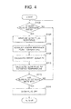
control unit 23 will be described with reference to the subroutine flowchart shown inFIG. 4 . - First, it is assumed that energization drive control processing of the
glow plug 1 is executed like conventional in theGCU 100. The energization drive control processing controls the energization of theglow plug 1—in other words, the making and breaking of electrical continuity of the energization control-use semiconductor element 31—depending on the driven state of an unillustrated engine. In the energization drive control processing, the making and breaking of electrical continuity of the energization control-use semiconductor element 31 is performed by pulse width modulation (PWM) control, for example. - Then, when processing is started by the arithmetic and
control unit 23, first, it is determined whether or not theglow plug 1 is ON, that is, whether or theglow plug 1 is being energized (see step S102 inFIG. 4 ). The arithmetic andcontrol unit 23 advances to the processing in next-described step S104 only in a case where it has been determined that theglow plug 1 is being energized (in the case of YES). In a case where it has been determined that theglow plug 1 is not yet being energized (in the case of NO), the determination processing is repeated until it is determined that theglow plug 1 is being energized. - In step S104, a measurement of the resistance of the
glow plug 1 is executed. - That is, a resistance value Rg of the
glow plug 1 is arithmetically calculated as Rg = (VB - Vr) ÷ (Vr ÷ R) by the arithmetic andcontrol unit 23. - Here, VB is the voltage of the
vehicle battery 25, Vr is the voltage drop in theresistor 32, and R is the resistance value of theresistor 32. Further, this arithmetic expression assumes that the voltage drop in the energization control-use semiconductor element 31 can be ignored. - The voltage drop Vr in the
resistor 32 is acquired via themeasurement circuit 22. - Next, a measurement of a heater reference point temperature is performed (see step S106 in
FIG. 4 ). - Here, the heater reference point temperature is necessary as a parameter for determining an offset quantity that is used in later-described glow plug tip temperature calculation processing (see step S110 in
FIG. 4 ). - Specifically, the heater reference point temperature in the embodiment of the present invention is the temperature of the heating element negative
electrode connecting portion 3a (seeFIG. 3 ) that is connected to the negative electrode-sideelectrode lead member 10a. The thermocouple 36 (seeFIG. 3 ) is attached to this site, and the temperature of that site is made measureable in the arithmetic andcontrol unit 23. - The heater reference point temperature is not limited to the heating element negative
electrode connecting portion 3a and may of course also be another arbitrary site on theglow plug 1. For example, an appropriate site on the metal sheath 3 outside the heating element negativeelectrode connecting portion 3a is suitable. - Next, an offset quantity calculation is performed (see step S108 in
FIG. 4 ), and a calculation of the glow plug tip temperature (estimated temperature) is performed using this offset quantity (see step S110 inFIG. 4 ). - First, in the embodiment of the present invention, a glow plug tip temperature Tg is calculated as Tg = Cg × Rg - Koff.
- Here, Cg is a constant that is determined by an electrical characteristic of the
glow plug 1. More specifically, Cg is a constant representing the relationship between the temperature and the resistance of theglow plug 1. The value of Cg is determined by the shape, material, and so forth of each part configuring theglow plug 1. - Further, Rg is the value of the glow plug resistance that was obtained in step S104.
- Additionally, Koff is an offset quantity. This offset quantity is determined as a value that offsets drift arising because of a change in the heater reference point temperature in the Cg x Rg portion of the arithmetic expression for obtaining the glow plug tip temperature Tg. In the embodiment of the present invention, this offset quantity is calculated and determined by a regression calculation or the like as a function of the heater reference point temperature.
- Additionally, the relationship between the heater reference point temperature and the offset quantity is made into an offset quantity calculation-use table or an arithmetic expression, is stored beforehand in an appropriate storage region of the arithmetic and
control unit 23, and is used for the glow plug tip temperature Tg. - The arithmetic expression for obtaining the glow plug tip temperature Tg was obtained as a result of devoted efforts by the present inventor described next.
- First, the correlation between glow plug tip temperature and glow plug resistance is expressed as a linear correlation, or in other words a linear function, and the present inventor was able to deduce from the results of tests and so forth that the correlation drifts in the Y-axial direction of the coordinate plane depending on the temperature of the
glow plug 1 itself. - As a result of performing, on the basis of the aforementioned knowledge, devoted tests and so forth to make this drift substantially offsettable regardless of the temperature of the
glow plug 1 itself, the present inventor came to the conclusion that adding the offset that is expressed as a function resulting from the heater reference point temperature described above to the linear function as a negative element is effective. As a result, this led to obtaining the above calculation expression of the glow plug tip temperature Tg. - The glow plug tip temperature Tg that has been obtained as described above is stored in an appropriate storage region of the arithmetic and
control unit 23 and is supplied for energization control of theglow plug 1 and fuel injection control as needed. - After the calculation of the glow plug tip temperature Tg, it is determined whether or not a glow plug OFF flag, which is a flag for judging whether or not it is necessary to stop the energization of the
glow plug 1, has been set—that is, whether or not the value of the glow plug OFF flag is a predetermined value (e.g., "1") that corresponds to stopping the energization of the glow plug 1 (see step S112 inFIG. 4 ). - Whether or not it is necessary to energize the
glow plug 1 is judged in the same-as-conventional glow plug energization control processing that is executed by the arithmetic andcontrol unit 23 and was taken as a precondition before, and the glow plug OFF flag is set as needed. - Then, in a case where it has been determined in step S112 that the glow plug OFF flag has been set (in the case of YES), that is, in a case where it has been determined that it is necessary to stop the energization of the
glow plug 1, the energization of theglow plug 1 is stopped, the series of processing steps is ended, and the arithmetic andcontrol unit 23 returns to an unillustrated main routine. - In a case where it has been determined in step S112 that the glow plug OFF flag has not been set (in the case of NO), that is, in a case where it has been judged that it is not necessary to stop the energization of the
glow plug 1, the arithmetic andcontrol unit 23 returns to step S102 and the series of processing steps is repeated. - In the above embodiment, the temperature of the heating element negative
electrode connecting portion 3a directly acquired by thethermocouple 36 is used as the heater reference point temperature, but it is not necessary for the heater reference point temperature to be limited to this. It is also suitable to use the temperature of another site—for example, the tip portion of the metal sheath 3— excluding the neighborhood of theheating element 7 of theglow plug 1. - Moreover, rather than a method of directly acquiring the heater reference point temperature with a thermocouple or the like, for example, a physical quantity that has been acquired by any of various sensors that are conventionally attached to a vehicle, such as, for example, engine cooling water temperature, engine speed, air intake volume, air intake temperature, etc., or the EGR rate, which is arithmetically calculated on the basis of various detection signals, or combustion pressure, etc., may also be substituted, converted to the heater reference point temperature, and used.
- Here, the analysis relating to the relationship between the temperature and the resistance of a glow plug by the present inventor that led to deducing the present invention generally referred to above will be more specifically described with reference to
FIG. 6 to FIG. 8 . - As shown in
FIG. 6 , a glow plug can be broadly divided into three portions: an A portion resulting from the heating element resulting from a ceramic resistor or the like; a C portion resulting from metal lead wires or the like; and a B portion that is a portion interconnecting the A portion and the C portion. -
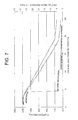
FIG. 7 shows an example of the partial resistances of the A portion, the B portion, and the C portion in this glow plug and an example of the temperature distribution in the lengthwise axial direction of the glow plug. - In
FIG. 7 , the horizontal axis represents distance from the tip portion (the A portion side) of the glow plug, the vertical axis on the right side represents partial resistances when the heater circuit (a circuit configured by the series connection of the A portion, the B portion, and the C portion) has been divided into units of 0.1 mm units, and the vertical axis on the left side represents temperature. - In
FIG. 7 , the solid line represents the partial resistance distribution when the temperature of the tip is 1200°C and the temperature of the cathode lead portion is 350°C. The dashed line represents the partial resistance distribution when the temperature of the tip is 1200°C and the temperature of the cathode lead portion is 250°C. InFIG. 7 , these two characteristic lines are slightly apart from each other in order make the drawing easier to see, but in actuality they are virtually superimposed. - The characteristic lines resulting from the solid line and the dashed line show that the resistances in the A portion, the B portion, and the C portion differ because of differences in their materials and so forth. That is, the range until the distance from the tip portion is approximately 5 mm represents the resistance of the A portion, and the partial resistance per 0.1 mm unit length is around about 30 mΩ. Further, the range where the distance from the tip portion is approximately 5 mm to 10 mm represents the resistance of the B portion, and the partial resistance per 0.1 mm unit length is around about 5 mΩ. Additionally, the portion where the distance from the tip portion is approximately 10 mm or more represents the resistance of the C portion, and the partial resistance per 0.1 mm unit length is around about 2 mΩ.
- Further, in
FIG. 7 , the double-dashed chain line characteristic line represents the temperature distribution in the lengthwise axial direction of the glow plug when the temperature of the tip is 1200°C and the temperature of the cathode lead portion is 350°C, and the single-dashed chain line characteristic line represents the temperature distribution in the lengthwise axial direction of the glow plug when the temperature of the tip is 1200°C and the temperature of the cathode lead portion is 250°C. - Normally it is possible to measure the temperature distribution in the lengthwise axial direction of the glow plug with a radiation thermometer, for example, but it is impossible to perform this measurement in a state in which the glow plug has been attached to the engine.
- Therefore, the present inventor arrived at deducing a method of estimating the glow plug tip temperature from the glow plug resistance and the temperature of a reference point with the following model.
- First, as shown in
FIG. 6 , the present inventor assumed a heater circuit where materials with different characteristics are series connected from the tip side as a heating portion A, a lead portion B, and a lead portion C. The present inventor hypothetically assumed that each portion in the circuit is a unit of a single cross-sectional area and a unit length. Additionally, assuming that Tg represents the temperature at the time of energization at a given portion, Tr represents room temperature which becomes a reference, Rr represents resistance at room temperature, and C represents a resistance temperature coefficient, then the partial resistance Rg can be expressed as Rg = Rr {1 + C (Tg - Tr)}. So the resistance ΣRg of the entire heater circuit at this time can be expressed as ΣRg = ΣRra {1 + Ca (Tga - Tr)} + ΣRrb {1 + Cb (Tgb - Tr)} + ΣRrc {1 + Cc (Tgc - Tr)}. - Here, Ca, Cb, Cc, Tr, Rra, Rrb, and Rrc are already known, so it suffices for ΣRg, Tgb, and Tgc to be solved in order to obtain Tga.
- In a case where Tgb and Tgc small enough that they can be ignored compared to Tga, then ΣRg can be approximated as ΣRg ≈ ΣRra {1 + Ca (Tga - Tr)}, but at the time of glow plug energization, there is electrothermal action and so Tgb and Tgc cannot be ignored. On the contrary, Tgb and Tgc change greatly depending on the operating state of the engine and in no small way affect ΣRg. On the other hand, Tgb exists on a line joining Tga and Tgc regardless of the operating state of the engine, so it is relatively easy to estimate Tgb from Tgc. That is, as a result, it becomes possible to precisely estimate Tga from ΣRg and Tgc.
- In
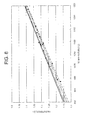
FIG. 8 , there is shown an example of characteristic lines representing the correlation (called "master curve" below) between glow plug resistance and glow plug tip temperature in cases where the cathode lead portion (seeFIG. 6 ) is taken as a reference point and the temperature of the reference point has been sectioned in 25°C intervals (275°C to 300°C, 300°C to 325°C, 325°C to 350°C, 350°C to 375°C, 375°C to 400°C, and 400°C to 425°C). - In
FIG. 8 , the dashed line characteristic line represents the correlation between glow plug resistance and glow plug tip temperature in a case where the reference point temperature is in the range of 275°C to 300°C, the double-dashed line characteristic line represents the correlation between glow plug resistance and glow plug tip temperature in a case where the reference point temperature is in the range of 300°C to 325°C, the single-dashed line characteristic line represents the correlation between glow plug resistance and glow plug tip temperature in a case where the reference point temperature is in the range of 375°C to 400°C, and the solid line characteristic line represents the correlation between glow plug resistance and glow plug tip temperature in a case where the reference point temperature is in the range of 400°C to 425°C. InFIG. 8 , in regard to the range where the reference point temperature is 325°C to 350°C and the range where the reference point temperature is 350°C to 375°C, these substantially overlap the characteristic lines in the reference point temperatures around these and it becomes difficult to distinguish between them, so these characteristic lines are omitted from the standpoint of making it easier to see the drawing and facilitating understanding. According toFIG. 8 , it can be understood that in a case where the cathode lead portion temperature is different, drift in the master curve arises because of the difference in the temperature distribution in the lengthwise axial direction of the glow plug and it is difficult to estimate the temperature of the tip of the glow plug with only the resistance of the glow plug. - As a result of performing various tests and so forth in light of this characteristic, the present inventor arrived at deducing that drift in the master curve can be substantially cancelled if the glow plug resistance and the temperature of the reference point are clearly known, and on the basis of this result the present inventor made the temperature of the tip of the glow plug estimable with high precision by the processing procedure described in
FIG. 4 above. - In
FIG. 5 , as a second example, a processing example in the case of substituting, as the heater reference point temperature, a physical quantity that has been acquired by a sensor is shown as a subroutine flowchart. The content thereof will be described below with reference toFIG. 5 . - The same reference numerals will be given to steps having the same processing content as the steps shown in
FIG. 4 , detailed description of those same steps will be omitted, and the points that are different will be centrally described below. - When processing by the arithmetic and
control unit 23 is started, like in the first example shown inFIG. 4 , it is determined whether or not theglow plug 1 is being energized (see step S102 inFIG. 5 ). When it is determined that theglow plug 1 is being energized, a measurement of the resistance of theglow plug 1 is executed (see step S104 inFIG. 5 ). - Next, as a substitute for the heater reference point temperature, an output signal of a sensor (not shown) is imported into the arithmetic and
control unit 23 and stored in an unillustrated appropriate storage region (see step S107 inFIG. 5 ). - Here, any of various sensors that are conventionally attached to a vehicle are suitable as the sensor; for example, a water temperature sensor for detecting the engine cooling water temperature, a speed sensor for detecting the engine speed, and an air intake sensor for detecting the air intake volume are suitable.
- Next, a calculation of the offset quantity Koff is performed on the basis of the sensor output value that was acquired in step S104 (see step S109 in
FIG. 5 ). - In the calculation of the offset quantity Koff, first, the sensor output value is converted into the heater reference point temperature—for example, the temperature in the heating element negative
electrode connecting portion 3a—using a predetermined conversion expression. Here, the predetermined conversion expression is set on the basis of tests, simulation results, and so forth in regard to the correlation between the sensor output value and the heater reference point temperature. - After the heater reference point temperature has been calculated, the offset quantity Koff is obtained from the heater reference point temperature like in S108 shown in
FIG. 4 . - Then, the glow plug tip temperature Tg is calculated as Tg = Cg x Rg - Koff (see step S110 in
FIG. 5 ). The calculated value is stored in an appropriate storage region of the arithmetic andcontrol unit 23 and is supplied for energization control of theglow plug 1 and fuel injection control as needed. - The present invention is suited for fuel injection control systems and so forth in vehicles where the estimated temperature of a glow plug tip whose precision is higher compared to conventional is desired.
Claims (6)
- A glow plug tip temperature estimating method comprising:correcting, with an offset that has been obtained on the basis of a predetermined heater reference point temperature, the result of multiplying a resistance value of a glow plug that has been actually measured and a constant that has been determined on the basis of an electrical characteristic of the glow plug; andtaking the result of that correction as an estimated temperature of the tip of the glow plug.
- The glow plug tip temperature estimating method according to claim 1, wherein
the predetermined heater reference point temperature is the temperature of an arbitrary site excluding the neighborhood of a heating element of the glow plug, and
the offset is a value that offsets drift resulting from a change in the heater reference point temperature that arises in the result of multiplying the resistance value of the glow plug that has been actually measured and the constant that has been determined on the basis of the electrical characteristic of the glow plug, with the offset being obtained by an arithmetic expression that has been determined such that the offset is calculated as a function of the heater reference point temperature. - The glow plug tip temperature estimating method according to claim 2, further comprising
substituting, as the temperature of the arbitrary site excluding the neighborhood of the heating element of the glow plug, an output of a predetermined sensor that is installed in a vehicle and
obtaining, on the basis of a correlation obtained beforehand between the sensor output and the temperature of the arbitrary site excluding the neighborhood of the heating element of the glow plug, the temperature of the arbitrary site excluding the neighborhood of the heating element of the glow plug that corresponds to the sensor output. - A glow plug drive control device comprising:an arithmetic and control unit that executes drive control of a glow plug; andan energization drive circuit that performs energization of the glow plug in response to the drive control of the glow plug that is executed by the arithmetic and control unit,wherein the arithmetic and control unit is configured to arithmetically calculate a resistance value of the glow plug on the basis of an energization current of the glow plug and a voltage applied to the glow plug, perform a multiplication of the resistance value of the glow plug that has been calculated and a constant that has been determined beforehand on the basis of an electrical characteristic of the glow plug, input a predetermined heater reference point temperature, calculate an offset with a predetermined offset arithmetic expression from the heater reference point temperature, correct the multiplication result with that offset, and calculate an estimated temperature of a tip of the glow plug.
- The glow plug drive control device according to claim 4, wherein
the predetermined heater reference point temperature is the temperature of an arbitrary site excluding the neighborhood of a heating element of the glow plug, and
the offset arithmetic expression is determined such that a value that offsets drift resulting from a change in the heater reference point temperature that arises in the result of multiplying the resistance value of the glow plug that has been actually measured and the constant that has been determined on the basis of the electrical characteristic of the glow plug is calculated as a function of the heater reference point temperature. - The glow plug drive control device according to claim 5, wherein the arithmetic and control unit is further configured to be capable of
inputting, as the temperature of the arbitrary site excluding the neighborhood of the heating element of the glow plug, an output of a predetermined sensor that is installed in a vehicle and
calculating, on the basis of a correlation obtained beforehand between the sensor outputand the temperature of the arbitrary site excluding the neighborhood of the heating element of the glow plug, the temperature of the arbitrary site excluding the neighborhood of the heating element of the glow plug that corresponds to the sensor output.
Applications Claiming Priority (1)
| Application Number | Priority Date | Filing Date | Title |
|---|---|---|---|
| JP2011003773A JP5660612B2 (en) | 2011-01-12 | 2011-01-12 | Glow plug tip temperature estimation method and glow plug drive control device |
Publications (2)
| Publication Number | Publication Date |
|---|---|
| EP2479422A2 true EP2479422A2 (en) | 2012-07-25 |
| EP2479422A3 EP2479422A3 (en) | 2015-03-11 |
Family
ID=45442954
Family Applications (1)
| Application Number | Title | Priority Date | Filing Date |
|---|---|---|---|
| EP11194857.6A Withdrawn EP2479422A3 (en) | 2011-01-12 | 2011-12-21 | Glow plug tip temperature estimating method and glow plug drive control device |
Country Status (3)
| Country | Link |
|---|---|
| US (1) | US9255564B2 (en) |
| EP (1) | EP2479422A3 (en) |
| JP (1) | JP5660612B2 (en) |
Cited By (2)
| Publication number | Priority date | Publication date | Assignee | Title |
|---|---|---|---|---|
| WO2014005803A1 (en) * | 2012-07-04 | 2014-01-09 | Robert Bosch Gmbh | Method and device for determining a temperature/resistance correlation of a pencil-type glow plug |
| EP4534907A4 (en) * | 2022-05-25 | 2026-04-29 | Chongqing Le Mark Tech Co Ltd | ELECTRIC FOUR-WIRE HEATING AND IGNITION DEVICE WITH TEMPERATURE MEASUREMENT |
Families Citing this family (4)
| Publication number | Priority date | Publication date | Assignee | Title |
|---|---|---|---|---|
| JP5835462B2 (en) * | 2012-03-14 | 2015-12-24 | 日産自動車株式会社 | Diesel engine control device and control method |
| US10018704B2 (en) | 2013-10-17 | 2018-07-10 | Mediatek Singapore Pte. Ltd. | Snooping sensor STA or neighbor AP ranging and positioning in wireless local area networks |
| JP6736254B2 (en) * | 2015-01-16 | 2020-08-05 | 日本特殊陶業株式会社 | Glow plug |
| JP6667327B2 (en) * | 2016-03-17 | 2020-03-18 | 日本特殊陶業株式会社 | Heating device and temperature estimation device |
Citations (1)
| Publication number | Priority date | Publication date | Assignee | Title |
|---|---|---|---|---|
| JP2001336468A (en) | 2000-03-22 | 2001-12-07 | Ngk Spark Plug Co Ltd | Glow plug control device, glow plug, and method for detecting ions in combustion chamber of engine |
Family Cites Families (50)
| Publication number | Priority date | Publication date | Assignee | Title |
|---|---|---|---|---|
| US2840067A (en) * | 1954-09-23 | 1958-06-24 | Hoffman Electronics Corp | Glow plug ignition systems or the like |
| US4162669A (en) * | 1977-02-22 | 1979-07-31 | Toyota Jidosha Kogyo Kabushiki Kaisha | Ignition system for rotary piston engines |
| JPS53146043A (en) * | 1977-05-24 | 1978-12-19 | Isuzu Motors Ltd | Auxiliary starter for engine |
| DE3212504A1 (en) * | 1982-04-03 | 1983-10-13 | KHD Canada Inc. Deutz R & D Devision, Montreal Quebec | PISTON PISTON COMBUSTION ENGINE WITH AN ELECTRONIC CENTRAL CONTROL UNIT |
| JPS5968569A (en) * | 1982-10-14 | 1984-04-18 | Nissan Motor Co Ltd | Preheating control device of diesel engine |
| JPS59141771A (en) * | 1983-02-03 | 1984-08-14 | Nippon Denso Co Ltd | Control device for diesel engine |
| DE3433367A1 (en) * | 1984-09-12 | 1986-03-20 | Robert Bosch Gmbh, 7000 Stuttgart | DEVICE FOR CONTROLLING THE ENERGY SUPPLY TO A HOT PLACE |
| US4607153A (en) * | 1985-02-15 | 1986-08-19 | Allied Corporation | Adaptive glow plug controller |
| JPS63113221A (en) * | 1986-10-29 | 1988-05-18 | Isuzu Motors Ltd | Combustion control device of space heater |
| JPS63127013A (en) * | 1986-11-15 | 1988-05-30 | Isuzu Motors Ltd | Comubstion controller of air heater |
| DE3737745A1 (en) * | 1987-11-06 | 1989-05-18 | Bosch Gmbh Robert | METHOD AND DEVICE FOR REGULATING THE TEMPERATURE, IN PARTICULAR OF GLOW PLUGS |
| US5144922A (en) * | 1990-11-01 | 1992-09-08 | Southwest Research Institute | Fuel ignition system for compression ignition engines |
| US5094198A (en) * | 1991-04-26 | 1992-03-10 | Cummins Electronics Company, Inc. | Air intake heating method and device for internal combustion engines |
| JP2570481Y2 (en) * | 1991-05-30 | 1998-05-06 | 自動車機器株式会社 | Self-temperature control glow plug |
| US5287831A (en) * | 1991-08-15 | 1994-02-22 | Nartron Corporation | Vehicle starter and electrical system protection |
| EP0534491B1 (en) * | 1991-09-27 | 1996-08-14 | Nippondenso Co., Ltd. | Fuel injection control system with split fuel injection for diesel engine |
| US5729456A (en) * | 1991-10-31 | 1998-03-17 | Nartron Corporation | Glow plug controller |
| US6148258A (en) * | 1991-10-31 | 2000-11-14 | Nartron Corporation | Electrical starting system for diesel engines |
| US6009369A (en) * | 1991-10-31 | 1999-12-28 | Nartron Corporation | Voltage monitoring glow plug controller |
| WO1993009346A1 (en) * | 1991-10-31 | 1993-05-13 | Nartron Corporation | Glow plug controller |
| US5285640A (en) * | 1992-07-21 | 1994-02-15 | Olivo John R | Integrated post-engine emissions heater, catalytic converter and muffler |
| JP3155084B2 (en) * | 1992-09-25 | 2001-04-09 | マツダ株式会社 | Engine glow plug control device |
| CA2112636A1 (en) * | 1993-12-30 | 1995-07-01 | Normand Dery | Remote starting system for a vehicle having a diesel engine |
| DE4446113C5 (en) * | 1994-12-22 | 2008-08-21 | J. Eberspächer GmbH & Co. KG | Ignition device for heaters |
| JP2000248963A (en) * | 1999-02-26 | 2000-09-12 | Honda Motor Co Ltd | Gas turbine engine |
| DE19959766A1 (en) * | 1999-12-11 | 2001-06-13 | Bosch Gmbh Robert | Glow plug |
| DE10028073C2 (en) * | 2000-06-07 | 2003-04-10 | Beru Ag | Method and circuit arrangement for heating a glow plug |
| JP2003109720A (en) * | 2001-09-28 | 2003-04-11 | Matsushita Electric Ind Co Ltd | Heating device, its control method, production equipment and workpiece using the same |
| DE10248802A1 (en) * | 2002-10-19 | 2004-04-29 | Robert Bosch Gmbh | Glow plug with greatly shortened control coil |
| JP3810744B2 (en) * | 2003-01-29 | 2006-08-16 | 日本特殊陶業株式会社 | Glow plug energization control device and glow plug energization control method |
| US6878903B2 (en) * | 2003-04-16 | 2005-04-12 | Fleming Circle Associates, Llc | Glow plug |
| DE10348391B3 (en) * | 2003-10-17 | 2004-12-23 | Beru Ag | Glow method for diesel engine glow plug, uses mathematical model for optimized heating of glow plug to its operating temperature |
| JP4089620B2 (en) * | 2004-01-15 | 2008-05-28 | 株式会社デンソー | Vehicle control system |
| ITBO20050326A1 (en) * | 2005-05-06 | 2006-11-07 | Magneti Marelli Powertrain Spa | INTERNAL COMBUSTION ENGINE PROVIDED WITH A HEATING DEVICE IN A COMBUSTION CHAMBER AND METHOD OF CHECKING THE HEATING DEVICE |
| US7632322B2 (en) * | 2005-06-07 | 2009-12-15 | Idatech, Llc | Hydrogen-producing fuel processing assemblies, heating assemblies, and methods of operating the same |
| DE102006010194B4 (en) * | 2005-09-09 | 2011-06-09 | Beru Ag | Method and device for operating the glow plugs of a self-igniting internal combustion engine |
| US7957885B2 (en) * | 2005-09-21 | 2011-06-07 | Kernwein Markus | Method for operating a group of glow plugs in a diesel engine |
| JP4816385B2 (en) * | 2006-10-02 | 2011-11-16 | 株式会社デンソー | Glow plug |
| US7631625B2 (en) * | 2006-12-11 | 2009-12-15 | Gm Global Technology Operations, Inc. | Glow plug learn and control system |
| JP4849040B2 (en) * | 2007-09-10 | 2011-12-28 | マツダ株式会社 | Diesel engine control device |
| US8183501B2 (en) * | 2007-12-13 | 2012-05-22 | Delphi Technologies, Inc. | Method for controlling glow plug ignition in a preheater of a hydrocarbon reformer |
| JP5179887B2 (en) * | 2008-01-15 | 2013-04-10 | 株式会社オートネットワーク技術研究所 | Glow plug control device and control method |
| GB2456784A (en) * | 2008-01-23 | 2009-07-29 | Gm Global Tech Operations Inc | Glow plug control unit and method for controlling the temperature in a glow plug |
| DE102008007271A1 (en) * | 2008-02-04 | 2009-08-06 | Robert Bosch Gmbh | Method for controlling at least one glow plug in an internal combustion engine and engine control unit |
| JP2009222031A (en) * | 2008-03-18 | 2009-10-01 | Toyota Motor Corp | Recovery processing method and device for glow plug-integrated cylinder internal sensor |
| EP2123901B1 (en) * | 2008-05-21 | 2013-08-28 | GM Global Technology Operations LLC | A method for controlling the operation of a glow-plug in a diesel engine |
| ATE528501T1 (en) * | 2008-05-21 | 2011-10-15 | Gm Global Tech Operations Inc | METHOD AND DEVICE FOR CONTROLLING Glow PINS IN A DIESEL ENGINE, IN PARTICULAR FOR MOTOR VEHICLES |
| JP4956486B2 (en) * | 2008-05-30 | 2012-06-20 | 日本特殊陶業株式会社 | Glow plug energization control device and glow plug energization control system |
| DE102009024138B4 (en) * | 2009-06-04 | 2012-02-02 | Beru Ag | Method for controlling the temperature of a glow plug |
| WO2013042488A1 (en) * | 2011-09-20 | 2013-03-28 | ボッシュ株式会社 | Glow plug diagnostic method and glow plug drive control device |
-
2011
- 2011-01-12 JP JP2011003773A patent/JP5660612B2/en not_active Expired - Fee Related
- 2011-12-21 EP EP11194857.6A patent/EP2479422A3/en not_active Withdrawn
-
2012
- 2012-01-12 US US13/349,381 patent/US9255564B2/en not_active Expired - Fee Related
Patent Citations (1)
| Publication number | Priority date | Publication date | Assignee | Title |
|---|---|---|---|---|
| JP2001336468A (en) | 2000-03-22 | 2001-12-07 | Ngk Spark Plug Co Ltd | Glow plug control device, glow plug, and method for detecting ions in combustion chamber of engine |
Cited By (2)
| Publication number | Priority date | Publication date | Assignee | Title |
|---|---|---|---|---|
| WO2014005803A1 (en) * | 2012-07-04 | 2014-01-09 | Robert Bosch Gmbh | Method and device for determining a temperature/resistance correlation of a pencil-type glow plug |
| EP4534907A4 (en) * | 2022-05-25 | 2026-04-29 | Chongqing Le Mark Tech Co Ltd | ELECTRIC FOUR-WIRE HEATING AND IGNITION DEVICE WITH TEMPERATURE MEASUREMENT |
Also Published As
| Publication number | Publication date |
|---|---|
| JP2012145035A (en) | 2012-08-02 |
| JP5660612B2 (en) | 2015-01-28 |
| US20120175360A1 (en) | 2012-07-12 |
| US9255564B2 (en) | 2016-02-09 |
| EP2479422A3 (en) | 2015-03-11 |
Similar Documents
| Publication | Publication Date | Title |
|---|---|---|
| US9255564B2 (en) | Glow plug tip temperature estimating method and glow plug drive control device | |
| US8217310B2 (en) | Glow plug electrification control apparatus and glow plug electrification control system | |
| EP3109607B1 (en) | Method for temperature drift compensation of temperature measurement device using thermocouple | |
| US20120063488A1 (en) | Temperature sensor and temperature sensor system | |
| EP2236799B1 (en) | Energization control apparatus for controlled component for a vehicle | |
| EP3625527B1 (en) | Thermocouple arrangement and method for measuring temperatures | |
| US7573275B2 (en) | Temperature sensor control apparatus | |
| ES2764443T3 (en) | Procedure and device to determine the internal resistance of a sensor element | |
| WO2011152776A1 (en) | Temperature measurement system and method for a temperature measurement system comprising at least one thermocouple | |
| EP0078427B1 (en) | Air flow meter | |
| EP3551980B1 (en) | Electronic circuit for driving a thermocouple element, temperature sensing device and method for observing a leakage resistance of the thermocouple element | |
| JP2009002347A (en) | Glow system, control part, and output control method for glow plug | |
| CN109496270B (en) | Processing apparatus | |
| EP2128428B1 (en) | Glow plug electrification control apparatus and glow plug electrification control system | |
| JP2017129054A (en) | Thermocouple abnormality detection apparatus and thermocouple abnormality detection method | |
| EP3046395B1 (en) | Heating apparatus, temperature estimation apparatus and heater control apparatus | |
| GB2557351A (en) | Method for measuring an absolute temperature at a hot-end side of a thermocouple element and measuring device comprising the thermocouple element | |
| US20100145652A1 (en) | Method for estimating the temperature in an internal combustion engine | |
| JPH0311577Y2 (en) | ||
| JP5351425B2 (en) | Output correction device for in-cylinder pressure sensor and in-cylinder pressure detection device having the same | |
| JPS6053814A (en) | Airflow-rate measuring device | |
| US20250271385A1 (en) | Gas sensor | |
| JP7088056B2 (en) | Particulate matter detection sensor | |
| EP3045714B1 (en) | Ion current measurement apparatus | |
| JP6736254B2 (en) | Glow plug |
Legal Events
| Date | Code | Title | Description |
|---|---|---|---|
| PUAI | Public reference made under article 153(3) epc to a published international application that has entered the european phase |
Free format text: ORIGINAL CODE: 0009012 |
|
| AK | Designated contracting states |
Kind code of ref document: A2 Designated state(s): AL AT BE BG CH CY CZ DE DK EE ES FI FR GB GR HR HU IE IS IT LI LT LU LV MC MK MT NL NO PL PT RO RS SE SI SK SM TR |
|
| AX | Request for extension of the european patent |
Extension state: BA ME |
|
| PUAL | Search report despatched |
Free format text: ORIGINAL CODE: 0009013 |
|
| AK | Designated contracting states |
Kind code of ref document: A3 Designated state(s): AL AT BE BG CH CY CZ DE DK EE ES FI FR GB GR HR HU IE IS IT LI LT LU LV MC MK MT NL NO PL PT RO RS SE SI SK SM TR |
|
| AX | Request for extension of the european patent |
Extension state: BA ME |
|
| RIC1 | Information provided on ipc code assigned before grant |
Ipc: F02D 41/24 20060101ALN20150203BHEP Ipc: F02P 19/02 20060101AFI20150203BHEP |
|
| 17P | Request for examination filed |
Effective date: 20150911 |
|
| RBV | Designated contracting states (corrected) |
Designated state(s): AL AT BE BG CH CY CZ DE DK EE ES FI FR GB GR HR HU IE IS IT LI LT LU LV MC MK MT NL NO PL PT RO RS SE SI SK SM TR |
|
| 17Q | First examination report despatched |
Effective date: 20170220 |
|
| STAA | Information on the status of an ep patent application or granted ep patent |
Free format text: STATUS: THE APPLICATION IS DEEMED TO BE WITHDRAWN |
|
| 18D | Application deemed to be withdrawn |
Effective date: 20190312 |