EP2479364A1 - Door-lock device for a household appliance door - Google Patents
Door-lock device for a household appliance door Download PDFInfo
- Publication number
- EP2479364A1 EP2479364A1 EP12425012A EP12425012A EP2479364A1 EP 2479364 A1 EP2479364 A1 EP 2479364A1 EP 12425012 A EP12425012 A EP 12425012A EP 12425012 A EP12425012 A EP 12425012A EP 2479364 A1 EP2479364 A1 EP 2479364A1
- Authority
- EP
- European Patent Office
- Prior art keywords
- slider
- strut
- lock device
- locking
- door
- Prior art date
- Legal status (The legal status is an assumption and is not a legal conclusion. Google has not performed a legal analysis and makes no representation as to the accuracy of the status listed.)
- Granted
Links
Images

Classifications
-
- E—FIXED CONSTRUCTIONS
- E05—LOCKS; KEYS; WINDOW OR DOOR FITTINGS; SAFES
- E05C—BOLTS OR FASTENING DEVICES FOR WINGS, SPECIALLY FOR DOORS OR WINDOWS
- E05C19/00—Other devices specially designed for securing wings, e.g. with suction cups
- E05C19/02—Automatic catches, i.e. released by pull or pressure on the wing
- E05C19/024—Automatic catches, i.e. released by pull or pressure on the wing with a bifurcated latch
-
- A—HUMAN NECESSITIES
- A47—FURNITURE; DOMESTIC ARTICLES OR APPLIANCES; COFFEE MILLS; SPICE MILLS; SUCTION CLEANERS IN GENERAL
- A47L—DOMESTIC WASHING OR CLEANING; SUCTION CLEANERS IN GENERAL
- A47L15/00—Washing or rinsing machines for crockery or tableware
- A47L15/42—Details
- A47L15/4251—Details of the casing
- A47L15/4257—Details of the loading door
- A47L15/4259—Arrangements of locking or security/safety devices for doors, e.g. door latches, switch to stop operation when door is open
-
- D—TEXTILES; PAPER
- D06—TREATMENT OF TEXTILES OR THE LIKE; LAUNDERING; FLEXIBLE MATERIALS NOT OTHERWISE PROVIDED FOR
- D06F—LAUNDERING, DRYING, IRONING, PRESSING OR FOLDING TEXTILE ARTICLES
- D06F37/00—Details specific to washing machines covered by groups D06F21/00 - D06F25/00
- D06F37/42—Safety arrangements, e.g. for stopping rotation of the receptacle upon opening of the casing door
-
- E—FIXED CONSTRUCTIONS
- E05—LOCKS; KEYS; WINDOW OR DOOR FITTINGS; SAFES
- E05B—LOCKS; ACCESSORIES THEREFOR; HANDCUFFS
- E05B47/00—Operating or controlling locks or other fastening devices by electric or magnetic means
- E05B47/06—Controlling mechanically-operated bolts by electro-magnetically-operated detents
-
- E—FIXED CONSTRUCTIONS
- E05—LOCKS; KEYS; WINDOW OR DOOR FITTINGS; SAFES
- E05C—BOLTS OR FASTENING DEVICES FOR WINGS, SPECIALLY FOR DOORS OR WINDOWS
- E05C5/00—Fastening devices with bolts moving otherwise than only rectilinearly and only pivotally or rotatively
-
- E—FIXED CONSTRUCTIONS
- E05—LOCKS; KEYS; WINDOW OR DOOR FITTINGS; SAFES
- E05B—LOCKS; ACCESSORIES THEREFOR; HANDCUFFS
- E05B15/00—Other details of locks; Parts for engagement by bolts of fastening devices
- E05B15/04—Spring arrangements in locks
- E05B2015/0431—Modifying spring characteristic or tension
-
- E—FIXED CONSTRUCTIONS
- E05—LOCKS; KEYS; WINDOW OR DOOR FITTINGS; SAFES
- E05B—LOCKS; ACCESSORIES THEREFOR; HANDCUFFS
- E05B15/00—Other details of locks; Parts for engagement by bolts of fastening devices
- E05B15/04—Spring arrangements in locks
- E05B2015/0493—Overcenter springs
-
- E—FIXED CONSTRUCTIONS
- E05—LOCKS; KEYS; WINDOW OR DOOR FITTINGS; SAFES
- E05B—LOCKS; ACCESSORIES THEREFOR; HANDCUFFS
- E05B15/00—Other details of locks; Parts for engagement by bolts of fastening devices
- E05B15/04—Spring arrangements in locks
- E05B2015/0496—Springs actuated by cams or the like
Definitions
- the present invention relates to a door-lock device for a household appliance door.
- the invention concerns a door-lock device for washing machines and household appliances in general, designed and manufactured to minimize the dimensions occupied.
- door-lock devices e.g. for washing machines, capable to prevent the opening of the door until the operation cycle of the household appliance is not ended.
- door lock device for a household appliance door, said door being provided with a locking prong
- said door lock device comprising a slider, provided with an internal compartment, and capable to assume a resting position and an operating position, a strut, placed in said compartment and slidable in it along said slider, a locking hook capable to interact with said locking prong, rotatably coupled with an end of said slider and cinematically connected with said strut, pushing means, placed within said compartment of said slider, arranged to exert a force on said strut so as to keep said strut in contact with said locking hook, so that when said prong interacts with said locking hook, said locking hook rotates and translates, engaging with said locking hook, and remaining engaged with said locking prong by the force exerted by said pushing means through said strut, so that said slider passes from said resting position to said operating position.
- said kinematic connection between said strut and said locking hook could be realized by a suitable shaping of the contact surfaces of said strut and said locking hook respectively.
- said door lock device could comprise an electronic unit comprising electrical terminals for the connection to a control unit of said household appliance, and a locking pin, capable to assume: an extracted position, in which said locking pin engages with said slider when it is in said operating position, so as to inhibit the return to said resting position, and wherein said electronic unit enables said household appliance to be activated; and a retracted position in which said locking pin is disengaged from said slider.
- said slider could have an opening in which said locking pin is engageable with said opening.
- said slider could include a wing whereon said opening is obtained.
- said pushing means could comprise a spring, arranged in compression, so as to exert a force on said strut.
- said door lock device could comprise adjustment means of the compression of said spring.
- said slider could have a seat
- said adjusting means could include a plate, arranged in said seat, said plate having a threaded hole, and a grain, engaged with said threaded hole of said plate, said spring being arranged between said grain and said strut.
- Said door-lock device 1 comprises a containment enclosure 20, in which an electronic unit 30 and a blocking mechanical unit 40 of a prong 50, integral with a door of a household appliance, is housed.
- Said containment enclosure 20 comprises a first 21 and a second 22 element.
- Said first element 21 has a first opening 21', for the introduction of the prong 50, so that it may interact with the blocking mechanical unit 40, and a second opening 21", whose function will be better explained in the following.
- Said electronic unit 30 has the electric terminals 31 for connecting with the control unit of the household appliance (not shown in the figures).
- Said electronic unit 30 also includes a locking pin 32, capable of assuming a retracted position, in which said electronic unit 30 prevents said household appliance to activate, and an extracted position, in which said electronic unit 30 allows said household appliance to operate.
- Said blocking mechanical unit 40 comprises a slider 41, internally hollow, in which an inner compartment 411 is identified.
- Said slider 41 also has a wing 412 on which an opening 413 is obtained, wherein said locking pin 32 of said electronic unit 30 is insertable.
- Said slider 41 is capable of assuming a resting position and an operating position, which will be better described below.
- said blocking mechanical unit 40 comprises a locking hook 42 rotatably engaged to a first end of said slider 41 by a pin 42'.
- Said locking hook 42 is arranged in correspondence to said first opening 21'.
- Said locking hook 42 is engageable with said prong 50.
- Said blocking mechanical unit 40 further comprises a strut 43, slidable within said compartment 411 of said slider 41.
- Said locking hook 42 and said strut 43 are cinematically connected.
- said kinematic connection is realized by a suitable shaping of the contact surfaces 431 and 421 respectively of said strut 43 and of said locking hook 42.
- the blocking mechanical unit also comprises a plate 44, insertable into a corresponding seat 414 of said slider 41, placed substantially near the second end of said slider 41, opposite to said first end.
- Said plate 44 has a threaded hole, in which a grain 45 is engageable by screwing.
- a spring 46, or thrust means in general is interposed in compression.
- the locking hook 42 is in the initial position shown, in which it is held by the action of the spring 46 on the strut 43. Also, in this initial position, the slider 41 is in said resting position, in which it is arranged in such a way that the opening 413 is not arranged overlapped to said locking pin 32, thus holding it in said retracted position, in which, as said above, the household appliance cannot be activated.
- prong 50 moves in the direction of arrow A, fitting into said first opening 21' and intercepting said hook 42 (see figure 7 ), thus causing, as a consequence of the shaping of said contact surfaces 431 and 421 respectively of said strut 43 and of said locking hook 42, the rotation of the locking hook 42 with respect to said slider 41, according to the arrow B, and the translation always of said hook 42.
- said locking hook 42 rotatably coupled with said slider 41, there is also a translation of said slider 41, which passes from said resting position to said operative position, as effect due to the translation of said locking hook 42.
- the locking hook 42 arranges (see figure 8 ) in such way that the opening 413 is is overlapped to said locking pin 32, thus releasing and allowing the passage of the same from said retracted position to said extended position.
- said locking pin 32 is in said extended position and inserted in said opening 413, said slider 41 cannot slide, therefore the prong cannot be disengaged from said hook 42 and therefore said door is closed, even forcing the opening, when the household appliance is in operation, as it is appropriate for safety reasons.
- said locking hook 42 is kept in the desired position by the action of the strut 43/spring 46 on the locking hook 42, as said locking hook cannot rotate back to its initial position, unless in case of sufficient force on the door to open it, due to the shaping of the contact surfaces 431 and 421 respectively of said strut 43 and of said locking hook 42.
- locking pin 32 is retracted by a suitable electronic control of the control unit of the household appliance to said electronic unit 30, thus releasing the slider 41. Opening the door, prong 50 is disengaged from said locking hook 42 by means of a sufficient force, suitable to overcome the force of the assembly strut 43/spring 46 on the locking hook 42.
- the mechanism makes, this time in the opposite way, the same kinematic movement described above, by rotating and translating, thus translating also slider 41, which arranges again in such way that opening 413 does not overlap said locking pin 32, i.e. passes from said operating position to said resting position.
- An advantage of the present invention is that the configuration of the components allows a reduced thickness of the door-lock device and a minimum dispersion of opening and closing forces. This is achieved in particular because the prong of the door causes a roto-translation movement of the locking hook and the elements that contribute to distribute the opening and closing forces (the spring and the strut) are integrated and contained witin the element that realizes the interlock (the slider).
- a further advantage of the present invention is a reduced impact of mutual positioning tolerances among the components.
Abstract
Description
- The present invention relates to a door-lock device for a household appliance door.
- More specifically, the invention concerns a door-lock device for washing machines and household appliances in general, designed and manufactured to minimize the dimensions occupied.
- In the following, the description will be directed to the use in a washing machine, but it is clear that the same should not be considered limited to this specific use.
- As it is well known, at present there are different kinds of door-lock devices, e.g. for washing machines, capable to prevent the opening of the door until the operation cycle of the household appliance is not ended.
- In general, such devices are electromechanical and occupy a significant space, even for the necessary toughnessthat they must have. However, the trend to the reduction of the size of household appliances in the field moves the household appliances manufacturers to reduce the size of even these devices. However, reducing the size of the devices already known would risk of making them too delicate and not very robust, thus unsafe. Instead, in case of use of more robust materials, such as metallic alloys, it would increase the cost of the final device.
- Moreover, size reduction implies low tolerances between the components, which, therefore, imply a further increase in production cost.
- In light of the above, it is an object of the present invention, therefore, to provide a door-lock device for a household appliance that is robust but has reduced dimensions, in particular that it is thin.
- These and other results are obtained according to the invention with a particular assembly and kinematics of the mechanical unit that holds engaged the door prong of the household appliance, when this is in operation.
- It is therefore a specific object of the present invention door lock device for a household appliance door, said door being provided with a locking prong, said door lock device comprising a slider, provided with an internal compartment, and capable to assume a resting position and an operating position, a strut, placed in said compartment and slidable in it along said slider, a locking hook capable to interact with said locking prong, rotatably coupled with an end of said slider and cinematically connected with said strut, pushing means, placed within said compartment of said slider, arranged to exert a force on said strut so as to keep said strut in contact with said locking hook, so that when said prong interacts with said locking hook, said locking hook rotates and translates, engaging with said locking hook, and remaining engaged with said locking prong by the force exerted by said pushing means through said strut, so that said slider passes from said resting position to said operating position.
- Always according to the invention, said kinematic connection between said strut and said locking hook could be realized by a suitable shaping of the contact surfaces of said strut and said locking hook respectively.
- Still according to the invention, said door lock device could comprise an electronic unit comprising electrical terminals for the connection to a control unit of said household appliance, and a locking pin, capable to assume: an extracted position, in which said locking pin engages with said slider when it is in said operating position, so as to inhibit the return to said resting position, and wherein said electronic unit enables said household appliance to be activated; and a retracted position in which said locking pin is disengaged from said slider.
- Advantageously according to the invention, said slider could have an opening in which said locking pin is engageable with said opening.
- Further according to the invention, said slider could include a wing whereon said opening is obtained.
- Always according to the invention, said pushing means could comprise a spring, arranged in compression, so as to exert a force on said strut.
- Still according to the invention, said door lock device could comprise adjustment means of the compression of said spring.
- Further according to the invention, said slider could have a seat, and said adjusting means could include a plate, arranged in said seat, said plate having a threaded hole, and a grain, engaged with said threaded hole of said plate, said spring being arranged between said grain and said strut.
- The present invention will be now described, for illustrative but not limitative purposes, according to its preferred embodiments, with particular reference to the figures of the enclosed drawings, wherein:
-
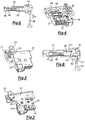
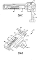
figure 1 shows an exploded view of the door-lock device for a door of a household appliance according to the present invention; -
figure 2 shows a first perspective view of the open device according tofigure 1 ; -
figure 3 shows the device according tofigure 2 in which it is applied a containment enclosure; -
figure 4 shows a second perspective view of the open device according tofigure 1 ; -
figure 5 shows a blocking mechanical unit of the device according tofigure 1 ; -
figure 6 shows a sectional side view of a device according to the invention when a door is open; -
figure 7 shows a sectional side view of a device according to the invention when the door is closed, and -
figure 8 shows a sectional side view of a device according to the invention when the door is closed. - In the various figures, similar parts will be indicated by the same reference numbers.
- Making reference to
figures 1 - 5 , the structure of a door-lock device 1 according to the present invention can be seen. Said door-lock device 1 comprises acontainment enclosure 20, in which anelectronic unit 30 and a blockingmechanical unit 40 of aprong 50, integral with a door of a household appliance, is housed. - Said
containment enclosure 20 comprises a first 21 and a second 22 element. Saidfirst element 21 has a first opening 21', for the introduction of theprong 50, so that it may interact with the blockingmechanical unit 40, and asecond opening 21", whose function will be better explained in the following. - Said
electronic unit 30 has theelectric terminals 31 for connecting with the control unit of the household appliance (not shown in the figures). Saidelectronic unit 30 also includes alocking pin 32, capable of assuming a retracted position, in which saidelectronic unit 30 prevents said household appliance to activate, and an extracted position, in which saidelectronic unit 30 allows said household appliance to operate. - Said blocking
mechanical unit 40 comprises aslider 41, internally hollow, in which aninner compartment 411 is identified. Saidslider 41 also has awing 412 on which anopening 413 is obtained, wherein said lockingpin 32 of saidelectronic unit 30 is insertable. Saidslider 41 is capable of assuming a resting position and an operating position, which will be better described below. - Moreover, said blocking
mechanical unit 40 comprises alocking hook 42 rotatably engaged to a first end of saidslider 41 by a pin 42'. Said lockinghook 42 is arranged in correspondence to said first opening 21'. Said lockinghook 42 is engageable with said prong 50. - Said blocking
mechanical unit 40 further comprises astrut 43, slidable within saidcompartment 411 of saidslider 41. Said lockinghook 42 and saidstrut 43 are cinematically connected. In particular, said kinematic connection is realized by a suitable shaping of thecontact surfaces strut 43 and of saidlocking hook 42. - The blocking mechanical unit also comprises a
plate 44, insertable into acorresponding seat 414 ofsaid slider 41, placed substantially near the second end of saidslider 41, opposite to said first end. Saidplate 44 has a threaded hole, in which agrain 45 is engageable by screwing. Finally, between saidgrain 45 and said strut, aspring 46, or thrust means in general, is interposed in compression. By the adjustment of the insertion of saidgrain 45 in saidplate 44 the compression of thespring 46 is possible to adjust and therefore the force exerted by it on saidstrut 43, to keep it in contact with saidlocking hook 42. - The operation of the
door lock device 1 described above is as follows. - When the door is opened and, therefore, the
prong 50 is disengaged from said blocking mechanical unit 40 (seefigure 6 ), thelocking hook 42 is in the initial position shown, in which it is held by the action of thespring 46 on thestrut 43. Also, in this initial position, theslider 41 is in said resting position, in which it is arranged in such a way that the opening 413 is not arranged overlapped to said lockingpin 32, thus holding it in said retracted position, in which, as said above, the household appliance cannot be activated. - Closing the door, prong 50 moves in the direction of arrow A, fitting into said first opening 21' and intercepting said hook 42 (see
figure 7 ), thus causing, as a consequence of the shaping of saidcontact surfaces strut 43 and of saidlocking hook 42, the rotation of thelocking hook 42 with respect to saidslider 41, according to the arrow B, and the translation always of saidhook 42. Being said lockinghook 42 rotatably coupled with saidslider 41, there is also a translation of saidslider 41, which passes from said resting position to said operative position, as effect due to the translation of saidlocking hook 42. In particular, once the introduction of theprong 50, thelocking hook 42 arranges (seefigure 8 ) in such way that the opening 413 is is overlapped to said lockingpin 32, thus releasing and allowing the passage of the same from said retracted position to said extended position. Moreover, when said lockingpin 32 is in said extended position and inserted in said opening 413, saidslider 41 cannot slide, therefore the prong cannot be disengaged from saidhook 42 and therefore said door is closed, even forcing the opening, when the household appliance is in operation, as it is appropriate for safety reasons. Moreover, saidlocking hook 42 is kept in the desired position by the action of thestrut 43/spring 46 on thelocking hook 42, as said locking hook cannot rotate back to its initial position, unless in case of sufficient force on the door to open it, due to the shaping of thecontact surfaces strut 43 and of saidlocking hook 42. - Even opening 21" of said
containment enclosure 20 is arranged overlapped on said lockingpin 32 and it is intended to be controlled from the outside or for a possible manual reset. - Then, when the household appliance has stopped working, locking
pin 32 is retracted by a suitable electronic control of the control unit of the household appliance to saidelectronic unit 30, thus releasing theslider 41. Opening the door,prong 50 is disengaged from saidlocking hook 42 by means of a sufficient force, suitable to overcome the force of theassembly strut 43/spring 46 on thelocking hook 42. The mechanism makes, this time in the opposite way, the same kinematic movement described above, by rotating and translating, thus translating alsoslider 41, which arranges again in such way that opening 413 does not overlap said lockingpin 32, i.e. passes from said operating position to said resting position. - An advantage of the present invention is that the configuration of the components allows a reduced thickness of the door-lock device and a minimum dispersion of opening and closing forces. This is achieved in particular because the prong of the door causes a roto-translation movement of the locking hook and the elements that contribute to distribute the opening and closing forces (the spring and the strut) are integrated and contained witin the element that realizes the interlock (the slider).
- A further advantage of the present invention is a reduced impact of mutual positioning tolerances among the components.
- The present invention has been described for illustrative but not limitative purposes, according to its preferred embodiments, but it is to be understood that modifications and/or changes can be introduced by those skilled in the art without departing from the relevant scope as defined in the enclosed claims.
Claims (8)
- Door lock device (1) for a household appliance door, said door being provided with a locking prong (50), said door lock device (1) comprising
a slider (41), provided with an internal compartment (411), and capable to assume a resting position and an operating position,
a strut (43), placed in said compartment (411) and slidable in it along said slider (41),
a locking hook (42) capable to interact with said locking prong (50), rotatably coupled with an end of said slider (41) and cinematically connected with said strut (43),
pushing means (46), placed within said compartment (411) of said slider (41), arranged to exert a force on said strut (43) so as to keep said strut (43) in contact with said locking hook (42),
so that when said prong (50) interacts with said locking hook (42), said locking hook (42) rotates and translates, engaging with said locking hook (42), and remaining engaged with said locking prong (42) by the force exerted by said pushing means (46) through said strut (43), so that said slider (41) passes from said resting position to said operating position. - Door lock device (1) according to claim 1, characterized that
said kinematic connection between said strut (43) and said locking hook (42) is realized by a suitable shaping of the contact surfaces (431, 421) of said strut (43) and said locking hook (42) respectively. - Door lock device (1) according to anyone of the preceding claims, characterized in that it comprises an electronic unit (30) comprising electrical terminals (31) for the connection to a control unit of said household appliance, and a locking pin (32), capable to assume:- an extracted position, in which said locking pin (32) engages with said slider (41) when it is in said operating position, so as to inhibit the return to said resting position, and wherein said electronic unit (30) enables said household appliance to be activated; and- a retracted position in which said locking pin (32) is disengaged from said slider (41).
- Door lock device (1) according to anyone of the preceding claims, characterized in that said slider (41) has an opening (413) in which said locking pin (32) is engageable with said opening (413).
- Door lock device (1) according to claim 4, characterized in that said slider (41) includes a wing (412) whereon said opening (413) is obtained.
- Door lock device (1) according to anyone of the preceding claims, characterized in that said pushing means comprise a spring (46), arranged in compression, so as to exert a force on said strut (43).
- Door lock device (1) according to claim 6, characterized in that it comprises adjustment means (44, 45) of the compression of said spring (46).
- Door lock device (1) according to claim 7, characterized
in that said slider (41) has a seat (414), and
in that said adjusting means include a plate (44), arranged in said seat (414), said plate having a threaded hole, and a grain (45), engaged with said threaded hole of said plate (44), said spring (46) being arranged between said grain (45) and said strut (43).
Applications Claiming Priority (1)
| Application Number | Priority Date | Filing Date | Title |
|---|---|---|---|
| ITRM2011A000026A IT1404221B1 (en) | 2011-01-24 | 2011-01-24 | DOOR-LOCK DEVICE FOR A DOOR OF A HOUSEHOLD APPLIANCE |
Publications (2)
| Publication Number | Publication Date |
|---|---|
| EP2479364A1 true EP2479364A1 (en) | 2012-07-25 |
| EP2479364B1 EP2479364B1 (en) | 2014-11-05 |
Family
ID=43975555
Family Applications (1)
| Application Number | Title | Priority Date | Filing Date |
|---|---|---|---|
| EP12425012.7A Active EP2479364B1 (en) | 2011-01-24 | 2012-01-20 | Door-lock device for a household appliance door |
Country Status (2)
| Country | Link |
|---|---|
| EP (1) | EP2479364B1 (en) |
| IT (1) | IT1404221B1 (en) |
Cited By (2)
| Publication number | Priority date | Publication date | Assignee | Title |
|---|---|---|---|---|
| CN108309185A (en) * | 2018-04-02 | 2018-07-24 | 佛山市顺德区美的洗涤电器制造有限公司 | Door lock assembly, the door lock assembly of dish-washing machine and the dish-washing machine with it |
| WO2020040653A1 (en) | 2018-08-22 | 2020-02-27 | Amica S.A. | Door opening mechanism for a household appliance, in particular an oven |
Families Citing this family (1)
| Publication number | Priority date | Publication date | Assignee | Title |
|---|---|---|---|---|
| CN108420382B (en) * | 2017-02-14 | 2022-10-18 | 青岛海尔洗碗机有限公司 | Dish washer lock mechanism and dish washer |
Citations (5)
| Publication number | Priority date | Publication date | Assignee | Title |
|---|---|---|---|---|
| EP0711896A2 (en) * | 1994-11-08 | 1996-05-15 | Wilhelm Weidtmann GmbH & Co. KG | Locking device for windows, doors, or the like |
| EP1304436A2 (en) * | 2001-10-22 | 2003-04-23 | BITRON S.p.A. | A door-lock, particularly for household appliances |
| EP1469147A2 (en) * | 2003-04-17 | 2004-10-20 | BITRON S.p.A. | A device for locking and unlocking the door of an electric household appliance |
| DE102006007418A1 (en) * | 2005-03-04 | 2006-09-07 | Ark-Les Corp., Stoughton | Latch for appliance e.g. dishwasher, has rotating hook to capture/release strike when it enters/exists the hook opening, and stop to hold carriage in position along line with spring in high compression state |
| EP2087829A1 (en) * | 2008-02-05 | 2009-08-12 | BITRON S.p.A. | Button device for blocking and releasing a door, particularly a door of a home appliance |
-
2011
- 2011-01-24 IT ITRM2011A000026A patent/IT1404221B1/en active
-
2012
- 2012-01-20 EP EP12425012.7A patent/EP2479364B1/en active Active
Patent Citations (5)
| Publication number | Priority date | Publication date | Assignee | Title |
|---|---|---|---|---|
| EP0711896A2 (en) * | 1994-11-08 | 1996-05-15 | Wilhelm Weidtmann GmbH & Co. KG | Locking device for windows, doors, or the like |
| EP1304436A2 (en) * | 2001-10-22 | 2003-04-23 | BITRON S.p.A. | A door-lock, particularly for household appliances |
| EP1469147A2 (en) * | 2003-04-17 | 2004-10-20 | BITRON S.p.A. | A device for locking and unlocking the door of an electric household appliance |
| DE102006007418A1 (en) * | 2005-03-04 | 2006-09-07 | Ark-Les Corp., Stoughton | Latch for appliance e.g. dishwasher, has rotating hook to capture/release strike when it enters/exists the hook opening, and stop to hold carriage in position along line with spring in high compression state |
| EP2087829A1 (en) * | 2008-02-05 | 2009-08-12 | BITRON S.p.A. | Button device for blocking and releasing a door, particularly a door of a home appliance |
Cited By (3)
| Publication number | Priority date | Publication date | Assignee | Title |
|---|---|---|---|---|
| CN108309185A (en) * | 2018-04-02 | 2018-07-24 | 佛山市顺德区美的洗涤电器制造有限公司 | Door lock assembly, the door lock assembly of dish-washing machine and the dish-washing machine with it |
| CN108309185B (en) * | 2018-04-02 | 2023-08-29 | 佛山市顺德区美的洗涤电器制造有限公司 | Door lock assembly, door lock assembly of dish washer and dish washer that has it |
| WO2020040653A1 (en) | 2018-08-22 | 2020-02-27 | Amica S.A. | Door opening mechanism for a household appliance, in particular an oven |
Also Published As
| Publication number | Publication date |
|---|---|
| ITRM20110026A1 (en) | 2012-07-25 |
| EP2479364B1 (en) | 2014-11-05 |
| IT1404221B1 (en) | 2013-11-15 |
Similar Documents
| Publication | Publication Date | Title |
|---|---|---|
| EP3542697B1 (en) | Door opening system for a domestic appliance | |
| EP2568864B1 (en) | A dishwasher comprising an automatic door opening mechanism | |
| US9995067B2 (en) | Door-lock device | |
| KR20100129753A (en) | Cam lock | |
| EP2278058A1 (en) | A device for locking the porthole door of washing and drying machines | |
| KR102251484B1 (en) | Bearing arrangement for a door | |
| EP2622156B1 (en) | System for opening a door, in particular for the door of a household appliance | |
| EP2450510A2 (en) | Door locking device for household appliances and bistable mechanism | |
| EP2087829A1 (en) | Button device for blocking and releasing a door, particularly a door of a home appliance | |
| US20150042105A1 (en) | Door-lock device for a door of a household appliance | |
| EP2479364B1 (en) | Door-lock device for a household appliance door | |
| CN107904866B (en) | Washing machine door lock | |
| AU2016257610B2 (en) | Locking device for a door of a domestic appliance | |
| EP3119936B1 (en) | Combined release door locking device | |
| CN103814167A (en) | Interlock mechanism for closing door of washing machines or tumble dryers | |
| KR200465812Y1 (en) | Automatic locking device for sliding windows | |
| EP3174440B1 (en) | Dispenser with openable door | |
| EP2482399A2 (en) | Interlocks for withdrawable breakers | |
| US20160168878A1 (en) | Foot pedal assembly for appliances | |
| JP5995690B2 (en) | Manual opening device for electromagnetic operating mechanism | |
| CN217001301U (en) | Door lock mechanism for electric appliance and household electric appliance | |
| DE102016214825A1 (en) | Domestic appliance with automatic door opening device and method for its operation | |
| DE102017203778A1 (en) | Domestic appliance with automatic door opening function and method of its operation | |
| CN210898254U (en) | Interlocking structure of switching on and switching off and rocking handle | |
| EP4116525A1 (en) | Electric door opener |
Legal Events
| Date | Code | Title | Description |
|---|---|---|---|
| PUAI | Public reference made under article 153(3) epc to a published international application that has entered the european phase |
Free format text: ORIGINAL CODE: 0009012 |
|
| AK | Designated contracting states |
Kind code of ref document: A1 Designated state(s): AL AT BE BG CH CY CZ DE DK EE ES FI FR GB GR HR HU IE IS IT LI LT LU LV MC MK MT NL NO PL PT RO RS SE SI SK SM TR |
|
| AX | Request for extension of the european patent |
Extension state: BA ME |
|
| 17P | Request for examination filed |
Effective date: 20130114 |
|
| RIC1 | Information provided on ipc code assigned before grant |
Ipc: E05C 19/02 20060101AFI20140327BHEP Ipc: A47L 15/42 20060101ALI20140327BHEP Ipc: E05C 5/00 20060101ALI20140327BHEP Ipc: E05B 47/06 20060101ALI20140327BHEP |
|
| GRAP | Despatch of communication of intention to grant a patent |
Free format text: ORIGINAL CODE: EPIDOSNIGR1 |
|
| INTG | Intention to grant announced |
Effective date: 20140604 |
|
| GRAS | Grant fee paid |
Free format text: ORIGINAL CODE: EPIDOSNIGR3 |
|
| GRAA | (expected) grant |
Free format text: ORIGINAL CODE: 0009210 |
|
| AK | Designated contracting states |
Kind code of ref document: B1 Designated state(s): AL AT BE BG CH CY CZ DE DK EE ES FI FR GB GR HR HU IE IS IT LI LT LU LV MC MK MT NL NO PL PT RO RS SE SI SK SM TR |
|
| REG | Reference to a national code |
Ref country code: GB Ref legal event code: FG4D |
|
| REG | Reference to a national code |
Ref country code: CH Ref legal event code: EP |
|
| REG | Reference to a national code |
Ref country code: AT Ref legal event code: REF Ref document number: 694763 Country of ref document: AT Kind code of ref document: T Effective date: 20141115 |
|
| REG | Reference to a national code |
Ref country code: IE Ref legal event code: FG4D |
|
| REG | Reference to a national code |
Ref country code: DE Ref legal event code: R096 Ref document number: 602012003676 Country of ref document: DE Effective date: 20141224 |
|
| REG | Reference to a national code |
Ref country code: AT Ref legal event code: MK05 Ref document number: 694763 Country of ref document: AT Kind code of ref document: T Effective date: 20141105 |
|
| REG | Reference to a national code |
Ref country code: NL Ref legal event code: VDEP Effective date: 20141105 |
|
| REG | Reference to a national code |
Ref country code: LT Ref legal event code: MG4D |
|
| PG25 | Lapsed in a contracting state [announced via postgrant information from national office to epo] |
Ref country code: IS Free format text: LAPSE BECAUSE OF FAILURE TO SUBMIT A TRANSLATION OF THE DESCRIPTION OR TO PAY THE FEE WITHIN THE PRESCRIBED TIME-LIMIT Effective date: 20150305 Ref country code: NL Free format text: LAPSE BECAUSE OF FAILURE TO SUBMIT A TRANSLATION OF THE DESCRIPTION OR TO PAY THE FEE WITHIN THE PRESCRIBED TIME-LIMIT Effective date: 20141105 Ref country code: NO Free format text: LAPSE BECAUSE OF FAILURE TO SUBMIT A TRANSLATION OF THE DESCRIPTION OR TO PAY THE FEE WITHIN THE PRESCRIBED TIME-LIMIT Effective date: 20150205 Ref country code: PT Free format text: LAPSE BECAUSE OF FAILURE TO SUBMIT A TRANSLATION OF THE DESCRIPTION OR TO PAY THE FEE WITHIN THE PRESCRIBED TIME-LIMIT Effective date: 20150305 Ref country code: ES Free format text: LAPSE BECAUSE OF FAILURE TO SUBMIT A TRANSLATION OF THE DESCRIPTION OR TO PAY THE FEE WITHIN THE PRESCRIBED TIME-LIMIT Effective date: 20141105 Ref country code: LT Free format text: LAPSE BECAUSE OF FAILURE TO SUBMIT A TRANSLATION OF THE DESCRIPTION OR TO PAY THE FEE WITHIN THE PRESCRIBED TIME-LIMIT Effective date: 20141105 Ref country code: FI Free format text: LAPSE BECAUSE OF FAILURE TO SUBMIT A TRANSLATION OF THE DESCRIPTION OR TO PAY THE FEE WITHIN THE PRESCRIBED TIME-LIMIT Effective date: 20141105 |
|
| PG25 | Lapsed in a contracting state [announced via postgrant information from national office to epo] |
Ref country code: PL Free format text: LAPSE BECAUSE OF FAILURE TO SUBMIT A TRANSLATION OF THE DESCRIPTION OR TO PAY THE FEE WITHIN THE PRESCRIBED TIME-LIMIT Effective date: 20141105 Ref country code: AT Free format text: LAPSE BECAUSE OF FAILURE TO SUBMIT A TRANSLATION OF THE DESCRIPTION OR TO PAY THE FEE WITHIN THE PRESCRIBED TIME-LIMIT Effective date: 20141105 Ref country code: HR Free format text: LAPSE BECAUSE OF FAILURE TO SUBMIT A TRANSLATION OF THE DESCRIPTION OR TO PAY THE FEE WITHIN THE PRESCRIBED TIME-LIMIT Effective date: 20141105 Ref country code: GR Free format text: LAPSE BECAUSE OF FAILURE TO SUBMIT A TRANSLATION OF THE DESCRIPTION OR TO PAY THE FEE WITHIN THE PRESCRIBED TIME-LIMIT Effective date: 20150206 Ref country code: CY Free format text: LAPSE BECAUSE OF FAILURE TO SUBMIT A TRANSLATION OF THE DESCRIPTION OR TO PAY THE FEE WITHIN THE PRESCRIBED TIME-LIMIT Effective date: 20141105 Ref country code: SE Free format text: LAPSE BECAUSE OF FAILURE TO SUBMIT A TRANSLATION OF THE DESCRIPTION OR TO PAY THE FEE WITHIN THE PRESCRIBED TIME-LIMIT Effective date: 20141105 Ref country code: LV Free format text: LAPSE BECAUSE OF FAILURE TO SUBMIT A TRANSLATION OF THE DESCRIPTION OR TO PAY THE FEE WITHIN THE PRESCRIBED TIME-LIMIT Effective date: 20141105 Ref country code: RS Free format text: LAPSE BECAUSE OF FAILURE TO SUBMIT A TRANSLATION OF THE DESCRIPTION OR TO PAY THE FEE WITHIN THE PRESCRIBED TIME-LIMIT Effective date: 20141105 |
|
| PG25 | Lapsed in a contracting state [announced via postgrant information from national office to epo] |
Ref country code: CZ Free format text: LAPSE BECAUSE OF FAILURE TO SUBMIT A TRANSLATION OF THE DESCRIPTION OR TO PAY THE FEE WITHIN THE PRESCRIBED TIME-LIMIT Effective date: 20141105 Ref country code: EE Free format text: LAPSE BECAUSE OF FAILURE TO SUBMIT A TRANSLATION OF THE DESCRIPTION OR TO PAY THE FEE WITHIN THE PRESCRIBED TIME-LIMIT Effective date: 20141105 Ref country code: SK Free format text: LAPSE BECAUSE OF FAILURE TO SUBMIT A TRANSLATION OF THE DESCRIPTION OR TO PAY THE FEE WITHIN THE PRESCRIBED TIME-LIMIT Effective date: 20141105 Ref country code: DK Free format text: LAPSE BECAUSE OF FAILURE TO SUBMIT A TRANSLATION OF THE DESCRIPTION OR TO PAY THE FEE WITHIN THE PRESCRIBED TIME-LIMIT Effective date: 20141105 |
|
| REG | Reference to a national code |
Ref country code: DE Ref legal event code: R097 Ref document number: 602012003676 Country of ref document: DE |
|
| REG | Reference to a national code |
Ref country code: CH Ref legal event code: PL |
|
| PG25 | Lapsed in a contracting state [announced via postgrant information from national office to epo] |
Ref country code: LU Free format text: LAPSE BECAUSE OF FAILURE TO SUBMIT A TRANSLATION OF THE DESCRIPTION OR TO PAY THE FEE WITHIN THE PRESCRIBED TIME-LIMIT Effective date: 20150120 |
|
| PLBE | No opposition filed within time limit |
Free format text: ORIGINAL CODE: 0009261 |
|
| STAA | Information on the status of an ep patent application or granted ep patent |
Free format text: STATUS: NO OPPOSITION FILED WITHIN TIME LIMIT |
|
| PG25 | Lapsed in a contracting state [announced via postgrant information from national office to epo] |
Ref country code: MC Free format text: LAPSE BECAUSE OF FAILURE TO SUBMIT A TRANSLATION OF THE DESCRIPTION OR TO PAY THE FEE WITHIN THE PRESCRIBED TIME-LIMIT Effective date: 20141105 |
|
| 26N | No opposition filed |
Effective date: 20150806 |
|
| PG25 | Lapsed in a contracting state [announced via postgrant information from national office to epo] |
Ref country code: CH Free format text: LAPSE BECAUSE OF NON-PAYMENT OF DUE FEES Effective date: 20150131 Ref country code: LI Free format text: LAPSE BECAUSE OF NON-PAYMENT OF DUE FEES Effective date: 20150131 |
|
| REG | Reference to a national code |
Ref country code: FR Ref legal event code: ST Effective date: 20150930 |
|
| REG | Reference to a national code |
Ref country code: IE Ref legal event code: MM4A |
|
| PG25 | Lapsed in a contracting state [announced via postgrant information from national office to epo] |
Ref country code: FR Free format text: LAPSE BECAUSE OF NON-PAYMENT OF DUE FEES Effective date: 20150202 |
|
| PG25 | Lapsed in a contracting state [announced via postgrant information from national office to epo] |
Ref country code: IE Free format text: LAPSE BECAUSE OF NON-PAYMENT OF DUE FEES Effective date: 20150120 |
|
| PG25 | Lapsed in a contracting state [announced via postgrant information from national office to epo] |
Ref country code: SI Free format text: LAPSE BECAUSE OF FAILURE TO SUBMIT A TRANSLATION OF THE DESCRIPTION OR TO PAY THE FEE WITHIN THE PRESCRIBED TIME-LIMIT Effective date: 20141105 |
|
| PG25 | Lapsed in a contracting state [announced via postgrant information from national office to epo] |
Ref country code: RO Free format text: LAPSE BECAUSE OF FAILURE TO SUBMIT A TRANSLATION OF THE DESCRIPTION OR TO PAY THE FEE WITHIN THE PRESCRIBED TIME-LIMIT Effective date: 20141105 |
|
| GBPC | Gb: european patent ceased through non-payment of renewal fee |
Effective date: 20160120 |
|
| PG25 | Lapsed in a contracting state [announced via postgrant information from national office to epo] |
Ref country code: GB Free format text: LAPSE BECAUSE OF NON-PAYMENT OF DUE FEES Effective date: 20160120 |
|
| PG25 | Lapsed in a contracting state [announced via postgrant information from national office to epo] |
Ref country code: MT Free format text: LAPSE BECAUSE OF FAILURE TO SUBMIT A TRANSLATION OF THE DESCRIPTION OR TO PAY THE FEE WITHIN THE PRESCRIBED TIME-LIMIT Effective date: 20141105 |
|
| PG25 | Lapsed in a contracting state [announced via postgrant information from national office to epo] |
Ref country code: SM Free format text: LAPSE BECAUSE OF FAILURE TO SUBMIT A TRANSLATION OF THE DESCRIPTION OR TO PAY THE FEE WITHIN THE PRESCRIBED TIME-LIMIT Effective date: 20141105 Ref country code: BG Free format text: LAPSE BECAUSE OF FAILURE TO SUBMIT A TRANSLATION OF THE DESCRIPTION OR TO PAY THE FEE WITHIN THE PRESCRIBED TIME-LIMIT Effective date: 20141105 Ref country code: HU Free format text: LAPSE BECAUSE OF FAILURE TO SUBMIT A TRANSLATION OF THE DESCRIPTION OR TO PAY THE FEE WITHIN THE PRESCRIBED TIME-LIMIT; INVALID AB INITIO Effective date: 20120120 |
|
| PG25 | Lapsed in a contracting state [announced via postgrant information from national office to epo] |
Ref country code: BE Free format text: LAPSE BECAUSE OF NON-PAYMENT OF DUE FEES Effective date: 20150131 |
|
| PG25 | Lapsed in a contracting state [announced via postgrant information from national office to epo] |
Ref country code: TR Free format text: LAPSE BECAUSE OF FAILURE TO SUBMIT A TRANSLATION OF THE DESCRIPTION OR TO PAY THE FEE WITHIN THE PRESCRIBED TIME-LIMIT Effective date: 20141105 |
|
| PG25 | Lapsed in a contracting state [announced via postgrant information from national office to epo] |
Ref country code: MK Free format text: LAPSE BECAUSE OF FAILURE TO SUBMIT A TRANSLATION OF THE DESCRIPTION OR TO PAY THE FEE WITHIN THE PRESCRIBED TIME-LIMIT Effective date: 20141105 |
|
| PG25 | Lapsed in a contracting state [announced via postgrant information from national office to epo] |
Ref country code: AL Free format text: LAPSE BECAUSE OF FAILURE TO SUBMIT A TRANSLATION OF THE DESCRIPTION OR TO PAY THE FEE WITHIN THE PRESCRIBED TIME-LIMIT Effective date: 20141105 |
|
| REG | Reference to a national code |
Ref country code: DE Ref legal event code: R119 Ref document number: 602012003676 Country of ref document: DE |
|
| REG | Reference to a national code |
Ref country code: DE Ref legal event code: R073 Ref document number: 602012003676 Country of ref document: DE |
|
| PG25 | Lapsed in a contracting state [announced via postgrant information from national office to epo] |
Ref country code: DE Free format text: LAPSE BECAUSE OF NON-PAYMENT OF DUE FEES Effective date: 20200801 |
|
| REG | Reference to a national code |
Ref country code: DE Ref legal event code: R074 Ref document number: 602012003676 Country of ref document: DE |
|
| PG25 | Lapsed in a contracting state [announced via postgrant information from national office to epo] |
Ref country code: DE Free format text: LAPSE BECAUSE OF NON-PAYMENT OF DUE FEES Effective date: 20200801 |
|
| PGRI | Patent reinstated in contracting state [announced from national office to epo] |
Ref country code: DE Effective date: 20201116 |
|
| PGFP | Annual fee paid to national office [announced via postgrant information from national office to epo] |
Ref country code: IT Payment date: 20230113 Year of fee payment: 12 Ref country code: DE Payment date: 20230119 Year of fee payment: 12 |