EP2479081A2 - Klinkenverschluss mit Verschlussklammerschraube - Google Patents
Klinkenverschluss mit Verschlussklammerschraube Download PDFInfo
- Publication number
- EP2479081A2 EP2479081A2 EP11179476A EP11179476A EP2479081A2 EP 2479081 A2 EP2479081 A2 EP 2479081A2 EP 11179476 A EP11179476 A EP 11179476A EP 11179476 A EP11179476 A EP 11179476A EP 2479081 A2 EP2479081 A2 EP 2479081A2
- Authority
- EP
- European Patent Office
- Prior art keywords
- screw
- locking
- bearing screw
- bearing
- head
- Prior art date
- Legal status (The legal status is an assumption and is not a legal conclusion. Google has not performed a legal analysis and makes no representation as to the accuracy of the status listed.)
- Granted
Links
Images


Classifications
-
- B—PERFORMING OPERATIONS; TRANSPORTING
- B61—RAILWAYS
- B61L—GUIDING RAILWAY TRAFFIC; ENSURING THE SAFETY OF RAILWAY TRAFFIC
- B61L5/00—Local operating mechanisms for points or track-mounted scotch-blocks; Visible or audible signals; Local operating mechanisms for visible or audible signals
- B61L5/10—Locking mechanisms for points; Means for indicating the setting of points
Definitions
- the present invention relates to a latch closure with a locking clip screw.
- pawls are used for adjustment of railway turnouts.
- the construction of a latch closure is in the European patent application EP 0 624 508 A1 described in great detail.
- the latch closure described therein for the positioning tongues of railway turnouts comprises an actuatable by means of a slide rod pawl and a closure piece, wherein the closure pawl pivotally mounted in a closure bearing and the positioning tongue is attached to the upper end of the closure bearing.
- Such locking bearings are used in railway switches to attract the Stellzonnespitzen to the adjacent rail edge and hold it.
- the positioning tongues are slidably guided over a certain length on the rail sleepers.
- the one end is in this case connected in fixed with the sleepers rail pieces, while the tongue tip is displaced by means of a device.
- the closure bearing lies in the closed position of the closure latch in a form-fitting manner against the closure piece. This prevents the lock bearing from twisting. This also prevents that twisted with this rotation, the positioning tongue and is lifted from the rail edge, respectively.
- Fig. 1 shows a view of the latch closure in the closed position.
- On a rail 1 is on one side of the rail foot Closure piece 2 by means of retaining clips 3, which hook under the rail at the other rail foot side attached.
- the adjusting tongue 4 of the switch is connected at its free end with a lock bearing 5.
- the adjusting tongue 4 is shown here in the adjacent position, ie the adjusting tongue 4 is pressed against the rail side.
- a closure pawl 6 is pivotally mounted in a bearing 7.
- a slide rod 8 is provided for the adjustment of the adjusting tongue 4, a slide rod 8 is provided. The slide rod 8 is moved transversely to the rail longitudinal axis by means of a drive, not shown.
- closure pawl 6 and the slide rod 8 are now designed such that the free end of the closure pawl 6 as in FIG. 1 shown under the foot of the rail 1 can slide through.
- This latch closure now causes the positioning tongue 4 to be positively connected via the locking pawl 6 to the rail 1 in the closed position.
- the setting of this connection can be achieved, for example, that the bearing 7 has an adjustment by means of eccentric.
- the orientation of the closure pawl 6 can be adjusted or readjusted such that a blocking surface 9 rests against the closure piece 2 with a defined clearance when the positioning tongue 4 bears against the flank of the rail 1.
- the lock stock 5 For mounting such a latch closure in a switch, inter alia, the lock stock 5 must be mounted at the foot of the adjusting tongue 4.
- the adjusting tongue 4 has a bore into which a locking screw 11 is screwed.
- the closure clip screw 11 is tightened according to the current state of the art with a maximum torque and then secured with a locking plate 12.
- the locking plate is designed as a spring plate and has a hole that corresponds to the screw head. It is first pushed over the hexagon head in the direction of the arrow and then snaps over the screw head when the screw head coincides with the hole in the locking plate 12.
- the hexagonal head of the locking clip screw 11 must be aligned with the locking plate 12, so that tightening the locking screw can be quite a re-tightening may be required by up to 60 °, which given the thread thickness of example M20 (and the associated thread pitches) again very much large forces required, which may possibly adversely affect the connected components.
- a first solution according to the invention for this task provides a closure bearing for a Weichenverstellan eleven with a foot of a Stellzunge penetrating locking bearing screw and a arranged between the foot and the screw head of the locking bearing screw spring assembly.
- the locking bearing screw with a relatively narrow definable Torque range are tightened and at the same time still has the rotational reserve to bring the position of the head of the locking bearing screw in accordance with a screw head depicting the hole in a locking plate, which then snaps when pushing over the head of the locking bearing screw as previously known.
- a second solution according to the invention for this purpose provides a closure bearing for a Weichenverstellan extract with a foot of a Stellzunge penetrating locking bearing screw and the head of the locking bearing screw annularly frictionally surrounding anti-rotation ring with an external toothing and adapted to this external toothing locking plate.
- the locking bearing screw it is also possible here to attract the locking bearing screw within a relatively small torque range and thereby align the locking bearing screw only in the Rast réellesmass the external teeth. If, for example, the outer toothing has a tooth number of 36 teeth, then the locking bearing screw must only be aligned within a range of a maximum of 10 °.
- the anti-rotation ring acts like an adapter for the Zahnungsmass and thus contributes to the fact that on the remaining construction of the lock bearing and the lock bearing screw no changes must be made, which is absolutely beneficial for safety and approval considerations.
- FIG. 2 shows a schematic view of the adjusting tongue 4 with the lock bearing 7 fixed thereto in one opposite FIG. 1 enlarged view.
- the head 13 of the closure bearing screw 11 sets the closure bearing 7 with vertical pressure on the positioning tongue 4.
- the head 13 has a hexagon.
- the designed as a spring plate locking plate 12 has a hole that corresponds to the hexagon surface area. If the locking plate 12 is now pushed over the head 13, it bends upwards and locks in the moment above the head 13 when the hole and the head 13 are in complete agreement. Therefore, the head 13 must be aligned exactly with the hole in the locking plate 12.
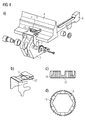
- FIG. 3a now shows the situation according to FIG. 2 with a spring package 14 inserted according to the invention under the head 13 of the closure bearing screw 11 (detail view cf. FIG. 3b ).
- the lock bearing screw 11 can be set within a small torque range.
- this solution allows for a further slight tightening of the locking bearing screw 11 in order to bring the position of the screw head 13 into conformity with the hole in the locking plate 12.
- the spring reserve present in the spring assembly 14 ensures that the screw connection does not cause any unacceptable stresses in the screwed components.
- FIG. 4 shows the situation according to FIG. 2 with an according to the invention on the head 13 of the locking bearing screw 11 mounted anti-rotation adapter 15.
- Anti-rotation adapter 15 is designed annular (see.
- Figure parts 4c and 4d has in its inner circumference a largely positive, but in any case non-positive course exactly to the course of the hexagonal head 13 of the locking bearing screw 11 (see Figure 4d part).
- the anti-rotation adapter 15 On its outer circumference, the anti-rotation adapter 15 has an outer toothing 16, which is much finer than the hexagon of the head 13.
- a hole 17 in the locking plate 12 ' forms the course of the external teeth 16 exactly, so that the locking plate 12' engages over the anti-rotation adapter 15, if External teeth 16 and the hole 17 are in agreement.
- the locking bearing screw 11 or its head 13 does not have to be aligned during tightening. Smaller corrections of the screw position are possible by means of an insertable into the screw head 13 pin, which allow the fine adjustment of the locking bearing screw 11 relative to the contours of the hole 17 in the locking plate 12 '.
Landscapes
- Engineering & Computer Science (AREA)
- Mechanical Engineering (AREA)
- Connection Of Plates (AREA)
- Seats For Vehicles (AREA)
- Train Traffic Observation, Control, And Security (AREA)
- Mechanical Control Devices (AREA)
Abstract
Description
- Die vorliegende Erfindung bezieht sich auf einen Klinkenverschluss mit einer Verschlussklammerschraube.
- Zur Verstellung von Eisenbahnweichen werden unter anderem auch Klinkenverschlüsse eingesetzt. Der Aufbau eines Klinkenverschlusses ist in der europäischen Patentanmeldung
EP 0 624 508 A1 sehr detailliert beschrieben. Der dort beschriebene Klinkenverschluss für die Stellzungen von Eisenbahnweichen umfasst eine mittels einer Schieberstange betätigbare Verschlussklinke und ein Verschlussstück, wobei die Verschlussklinke in einem Verschlusslager schwenkbar angeordnet und die Stellzunge am oberen Ende des Verschlusslagers befestigt ist. - Derartige Verschlusslager werden in Eisenbahnweichen eingesetzt, um die Stellzungenspitzen an die benachbarte Schienenflanke heranzuziehen und daran festzuhalten. Die Stellzungen sind dabei über eine bestimmte Länge gleitbar auf den Schienenschwellen geführt. Das eine Ende geht dabei in fest mit den Schwellen verbundene Schienenstücke über, während die Zungenspitze mittels einer Vorrichtung verschiebbar ist. In Schliesslage wird dabei die Zungenspitze an die benachbarte Schienenflanke herangezogen und daran gehalten resp. geklammert, während es in der offenen Stellung mit einem bestimmten Abstand von der Schienenflanke positioniert wird. Bei dem dort offenbarten Klinkenverschluss liegt das Verschlusslager in geschlossener Stellung der Verschlussklinke formschlüssig am Verschlussstück anliegt. Damit wird verhindert, dass sich das Verschlusslager verdrehen kann. Damit wird auch verhindert, dass sich mit dieser Verdrehung die Stellzunge verdreht und von der Schienenflanke abgehoben wird resp. dass es zu einer Klaffung zwischen Schienenflanke und Zungenspitze kommt.
Fig. 1 zeigt eine Ansicht des Klinkenverschlusses in geschlossener Stellung. An einer Schiene 1 ist auf einer Seite des Schienenfusses ein Verschlussstück 2 mittels Halteklammern 3, welche unter der Schiene hindurch an der anderen Schienenfussseite einhaken, angebracht. Die Stellzunge 4 der Weiche ist an ihrem freien Ende mit einem Verschlusslager 5 verbunden. Die Stellzunge 4 ist hier in der anliegenden Stellung dargestellt, d.h. die Stellzunge 4 ist an die Schienenflanke angedrückt. Am Verschlusslager 5 ist eine Verschlussklinke 6 in einem Lager 7 verschwenkbar angeordnet. Für die Verstellung der Stellzunge 4 ist eine Schieberstange 8 vorgesehen. Die Schieberstange 8 wird mittels eines nicht dargestellten Antriebs quer zur Schienenlängsachse bewegt. Die Verschlussklinke 6 und die Schieberstange 8 sind nun derart ausgebildet, dass das freie Ende der Verschlussklinke 6 wie inFigur 1 dargestellt unter dem Fuss der Schiene 1 hindurch gleiten kann. Dieser Klinkenverschluss bewirkt nun, dass in der geschlossenen Stellung die Stellzunge 4 formschlüssig über die Verschlussklinke 6 mit der Schiene 1 verbunden ist. Die Einstellung dieser Verbindung kann beispielsweise dadurch erreicht werden, dass das Lager 7 eine Einstellmöglichkeit mittels Exzenter besitzt. Damit kann die Ausrichtung der Verschlussklinke 6 derart eingestellt oder nachgestellt werden, dass eine Sperrfläche 9 mit definiertem Spiel an dem Verschlussstück 2 anliegt, wenn die Stellzunge 4 an der Flanke der Schiene 1 anliegt. - Bei solchen Sperrklinken kann nun das Problem auftreten, dass sich die Stellzunge 4 axial verdrehen kann. Dieses Verdrehen führt zu einem Abheben resp. Klaffen des oberen Bereiches der Stellzunge 4 von der Flanke der Schiene 1. Schon ein Abheben resp. Klaffen der Stellzunge um wenige Millimeter kann ungewünschte Folgen haben, indem dadurch die Räder eines Zuges an dieser Stelle anstossen können. Um dieses Problem zu lösen, ist am Fuss des Verschlusslagers 5 ein Steg 9 vorgesehen sein, welcher in geschlossener Stellung der Sperrklinke mit dem Fuss des Verschlussstückes 2 in Anschlag gelangt, wie in
Figur 1 dargestellt. Durch diese Massnahme wird ein Verdrehen und damit ein Abheben der Stellzunge 4 von der Flanke der Schiene 1 auf einfach Weise wirkungsvoll verhindert. - Zur Montage eines derartigen Klinkenverschlusses in einer Weiche muss unter anderem das Verschlusslager 5 am Fuss der Stellzunge 4 montiert werden. Hierzu weist die Stellzunge 4 eine Bohrung auf, in die eine Verschlussklammerschraube 11 eingeschraubt wird. Dabei wird die Verschlussklammerschraube 11 gemäss dem heutigen Stand der Technik mit einem maximalen Drehmoment angezogen und anschliessend mit einem Sicherungsblech 12 gesichert. Das Sicherungsblech ist dabei als Federblech ausgestaltet und weist ein Loch auf, dass dem Schraubenkopf entspricht. Es wird dabei in Pfeilrichtung zunächst über den Sechskantkopf geschoben und rastet dann über dem Schraubenkopf ein, wenn der Schraubenkopf mit dem Loch im Sicherungsblech 12 übereinstimmt. Damit muss der Sechskantkopf der Verschlussklammerschraube 11 zu dem Sicherungsblech 12 ausgerichtet werden, so dass beim Festziehen der Verschlussklammerschraube durchaus ein nochmaliges Nachziehen um bis zu 60° erforderlich sein kann, was angesichts der Gewindestärken von beispielsweise M20 (und der damit verbundenen Gewindesteigungen) noch einmal sehr grosse Kräfte erforderlich macht, die möglicherweise ungünstig auf die verbundenen Bauteile wirken können.
- Es ist daher die Aufgabe der vorliegenden Erfindung eine Lösung für die Befestigung des Verschlusslagers am Fuss der Stellzunge anzugeben, welche sich durch eine vereinfachte und die Bauteile weniger belastende Montage auszeichnet.
- Eine erste erfindungsgemässe Lösung für diese Aufgabe sieht ein Verschlusslager für eine Weichenverstellanordnung mit einer einen Fuss einer Stellzunge durchdringenden Verschlusslagerschraube und einem zwischen dem Fuss und dem Schraubenkopf der Verschlusslagerschraube angeordneten Federpaket vor. Auf diese Weise kann die Verschlusslagerschraube mit einem relativ schmal definierbaren Drehmomentbereich angezogen werden und hat dabei gleichzeitig noch die Drehreserve, um die Position des Kopfes der Verschlusslagerschraube in Übereinstimmung mit einem den Schraubenkopf abbildenden Loch in einem Sicherungsblech zu bringen, dass dann beim Einschieben wie bisher bekannt über den Kopf der Verschlusslagerschraube einrastet.
- Eine zweite erfindungsgemässe Lösung für diese Aufgabe sieht ein Verschlusslager für eine Weichenverstellanordnung mit einer einen Fuss einer Stellzunge durchdringenden Verschlusslagerschraube und einen den Kopf der Verschlusslagerschraube ringförmig kraftschlüssig umgebenden Drehsicherungsring mit einer Aussenverzahnung sowie ein an diese Aussenverzahnung angepasstes Sicherungsblech vor. Damit ist es hier ebenfalls möglich, die Verschlusslagerschraube innerhalb eines relativ kleinen Drehmomentbereichs anzuziehen und dabei die Verschlusslagerschraube nur in dem Rasterungsmass der Aussenverzahnung ausrichten zu müssen. Hat also beispielsweise die Aussenverzahnung eine Zahnzahl von 36 Zähnen, so muss die Verschlusslagerschraube nur innerhalb eines Bereichs von maximal 10° ausgerichtet werden. Der Drehsicherungsring wirkt dabei wie ein Adapter für das Zahnungsmass und trägt so dazu bei, dass an der übrigen Konstruktion des Verschlusslager und der Verschlusslagerschraube keine Veränderungen vorgenommen werden müssen, was auch sicherheits- und Genehmigungserwägungen absolut vorteilhaft ist.
- Bevorzugte Ausführungsbeispiele werden nachfolgend anhand einer Zeichnung näher erläutert. Dabei zeigen:
- Figur 1
- eine schematische Seitenansicht eines im Einsatz befindlichen Klinkenverschlusses mit einem an einer Stockschiene verspannten Verschlussstück und einem an einer Stellzunge festgesetzten Verschlusslager gemäss dem Stand der Technik;
- Figur 2
- eine vergrösserte Ansicht der Stellzunge mit daran festgesetztem Verschlusslager gemäss dem Stand der Technik;
- Figur 3
- eine schematische Ansicht eines Verschlusslagers mit eingelegtem Federpaket; und
- Figur 4
- eine schematische Ansicht eines Verschlusslagers mit auf die Verschlussklammerschraube ausgesetzten Drehsicherungs-Adapter.
-
Figur 2 zeigt eine schematische Ansicht der Stellzunge 4 mit dem daran festgesetzten Verschlusslager 7 in einer gegenüberFigur 1 vergrösserten Darstellung. Der Kopf 13 der Verschlusslagerschraube 11 setzt das Verschlusslager 7 mit senkrechtem Andruck an der Stellzunge 4 fest. Der Kopf 13 weist einen Sechskant auf. Das als Federblech ausgestaltete Sicherungsblech 12 weist ein Loch auf, das dem Sechskant flächenmässig entspricht. Wird das Sicherungsblech 12 nun über den Kopf 13 geschoben, verbiegt es sich nach oben und rastet in dem Moment über dem Kopf 13 ein, wenn das Loch und der Kopf 13 in vollständiger Übereinstimmung sind. Daher muss der Kopf 13 exakt auf das Loch im Sicherungsblech 12 ausgerichtet werden. -
Figur 3a zeigt nun die Situation gemässFigur 2 mit einem erfindungsgemäss unter dem Kopf 13 der Verschlusslagerschraube 11 eingelegten Federpaket 14 (Detailansicht vgl.Figur 3b ). Damit kann die Verschlusslagerschraube 11 innerhalb eines geringen Drehmomentbereichs festgesetzt werden. Gleichzeitig lässt diese Lösung ein weiteres geringes Anziehen der Verschlusslagerschraube 11 zu, um die Position des Schraubenkopfes 13 in Übereinstimmung mit dem Loch in dem Sicherungsblech 12 zu bringen. Dabei sorgt die im Federpaket 14 vorhandene Federreserve dafür, dass die Verschraubung keine unzulässigen Spannungen in den verschraubten Bauteilen verursacht.Figur 4 zeigt die Situation gemässFigur 2 mit einem erfindungsgemäss auf den Kopf 13 der Verschlusslagerschraube 11 aufgesetzten Drehsicherungsadapter 15. Der - Drehsicherungsadapter 15 ist ringförmig ausgestaltet (vgl.
- Figurenteile 4c und 4d) und weist in seinem Innenumfang einen weitgehend formschlüssigen, aber in jedem Fall kraftschlüssigen Verlauf exakt zum Verlauf des sechskantförmigen Kopf 13 der Verschlusslagerschraube 11 auf (vgl. Figurenteil 4d). An seinem Aussenumfang weist der Drehsicherungsadapter 15 eine Aussenverzahnung 16, die wesentlich feiner ist als der Sechskant des Kopfes 13. Ein Loch 17 im Sicherungsblech 12' bildet den Verlauf der Aussenverzahnung 16 exakt nach, sodass das Sicherungsblech 12' über dem Drehsicherungsadapter 15 einrastet, wenn Aussenverzahnung 16 und das Loch 17 in Übereinstimmung sind. Damit muss die Verschlusslagerschraube 11 bzw. ihr Kopf 13 gar nicht während des Anziehens ausgerichtet werden. Kleinere Korrekturen der Schraubenposition sind mittels eines in den Schraubenkopf 13 einführbaren Stifts möglich, die die Feinjustierung der Verschlusslagerschraube 11 relativ zu den Umrissen des Lochs 17 im Sicherungsblech 12' erlauben.
Claims (1)
- Verschlusslager (5) für eine Weichenverstellanordnung mit einer einen Fuss einer Stellzunge (4) durchdringenden Verschlusslagerschraube (11) und einen den Kopf (13) der Verschlusslagerschraube ringförmig umgebenden Drehsicherungsadapter (15) mit einer Aussenverzahnung (16) sowie eine an diese Aussenverzahnung (16) angepassten Sicherungsblech (12').
Priority Applications (2)
| Application Number | Priority Date | Filing Date | Title |
|---|---|---|---|
| EP11179476.4A EP2479081B1 (de) | 2011-01-19 | 2011-08-31 | Klinkenverschluss mit Verschlussklammerschraube |
| PL11179476T PL2479081T3 (pl) | 2011-01-19 | 2011-08-31 | Zamknięcie zapadkowe ze śrubą klamry zamykającej |
Applications Claiming Priority (2)
| Application Number | Priority Date | Filing Date | Title |
|---|---|---|---|
| EP11151348 | 2011-01-19 | ||
| EP11179476.4A EP2479081B1 (de) | 2011-01-19 | 2011-08-31 | Klinkenverschluss mit Verschlussklammerschraube |
Publications (3)
| Publication Number | Publication Date |
|---|---|
| EP2479081A2 true EP2479081A2 (de) | 2012-07-25 |
| EP2479081A3 EP2479081A3 (de) | 2015-10-28 |
| EP2479081B1 EP2479081B1 (de) | 2016-12-14 |
Family
ID=44509073
Family Applications (1)
| Application Number | Title | Priority Date | Filing Date |
|---|---|---|---|
| EP11179476.4A Active EP2479081B1 (de) | 2011-01-19 | 2011-08-31 | Klinkenverschluss mit Verschlussklammerschraube |
Country Status (4)
| Country | Link |
|---|---|
| US (1) | US8708287B2 (de) |
| EP (1) | EP2479081B1 (de) |
| CN (1) | CN102602429B (de) |
| PL (1) | PL2479081T3 (de) |
Families Citing this family (2)
| Publication number | Priority date | Publication date | Assignee | Title |
|---|---|---|---|---|
| NL2006119C2 (nl) * | 2011-02-02 | 2012-08-06 | Spot Safety Professionals On Track | Klemmechanisme voor het vastzetten van ten minste een voorwerp aan een rail alsmede een samenstel. |
| CN112389501B (zh) * | 2020-12-05 | 2024-09-20 | 中铁宝桥集团有限公司 | 中低速磁浮道岔锁销防转装置及锁销防转方法 |
Citations (1)
| Publication number | Priority date | Publication date | Assignee | Title |
|---|---|---|---|---|
| EP0624508A1 (de) | 1993-05-10 | 1994-11-17 | Siemens Integra Verkehrstechnik Ag | Klinkenverschluss für Eisenbahnweichen |
Family Cites Families (6)
| Publication number | Priority date | Publication date | Assignee | Title |
|---|---|---|---|---|
| US2250891A (en) * | 1940-09-11 | 1941-07-29 | Morden Frog & Crossing Works | Rail brace |
| GB743247A (en) * | 1952-08-21 | 1956-01-11 | Federico Pischek | Improvements in locking means for securing a nut on a screwed member |
| US2904256A (en) * | 1953-12-15 | 1959-09-15 | American Brake Shoe Co | Adjustable rail brace |
| DE19502105C5 (de) * | 1995-01-24 | 2004-12-30 | Carl Dan. Peddinghaus Gmbh & Co Kg | Verschlußvorrichtung für Weichenzungen |
| EP1414730B1 (de) * | 2001-07-30 | 2006-04-05 | Inventio Ag | Verfahren und vorrichtung zum befestigen einer führungsschiene |
| CN201083224Y (zh) * | 2007-08-07 | 2008-07-09 | 国网南京自动化研究院 | 防盗螺栓 |
-
2011
- 2011-08-31 EP EP11179476.4A patent/EP2479081B1/de active Active
- 2011-08-31 PL PL11179476T patent/PL2479081T3/pl unknown
-
2012
- 2012-01-18 CN CN201210015136.0A patent/CN102602429B/zh active Active
- 2012-01-18 US US13/352,398 patent/US8708287B2/en not_active Expired - Fee Related
Patent Citations (1)
| Publication number | Priority date | Publication date | Assignee | Title |
|---|---|---|---|---|
| EP0624508A1 (de) | 1993-05-10 | 1994-11-17 | Siemens Integra Verkehrstechnik Ag | Klinkenverschluss für Eisenbahnweichen |
Also Published As
| Publication number | Publication date |
|---|---|
| PL2479081T3 (pl) | 2017-06-30 |
| CN102602429B (zh) | 2016-06-15 |
| US8708287B2 (en) | 2014-04-29 |
| US20120181394A1 (en) | 2012-07-19 |
| CN102602429A (zh) | 2012-07-25 |
| EP2479081B1 (de) | 2016-12-14 |
| EP2479081A3 (de) | 2015-10-28 |
Similar Documents
| Publication | Publication Date | Title |
|---|---|---|
| EP2318723B1 (de) | Befestigungsanordnung mit toleranzausgleich | |
| EP1805427A1 (de) | Zug-druck-stange | |
| EP0400224A2 (de) | Enossales Einzelzahnimplantat sowie Konterwerkzeug zur Verwendung bei einem derartigen Implantat | |
| DE9409123U1 (de) | Vorrichtung zum Stabilisieren bzw. Komprimieren oder Distrahieren von Abschnitten der Wirbelsäule | |
| DE4235801A1 (de) | Dentalimplantat | |
| EP2032864B1 (de) | Scheibe und damit versehene schraubenverbindung | |
| EP3586018B1 (de) | Befestigungsvorrichtung und befestigungsbaugruppe | |
| DE3404118A1 (de) | Verfahren und vorrichtung zum anbringen einer mutter an einem plattenfoermigen werkstueck | |
| EP0905389A2 (de) | Betonschraube | |
| EP2816243B1 (de) | Befestigungselement | |
| EP2479080A2 (de) | Klinkenverschluss mit Verschlussklammerschraube | |
| EP2479081B1 (de) | Klinkenverschluss mit Verschlussklammerschraube | |
| EP3581811A1 (de) | System zur befestigung einer ersten komponente an einer zweiten komponente | |
| EP4012200B1 (de) | Federbelasteter rastbolzen | |
| DE102020205995B3 (de) | Toleranzausgleichsvorrichtung | |
| DE102009037820C5 (de) | Anordnung zur Verbindung von Holzbauteilen | |
| DE29805045U1 (de) | Kunststoffmutter | |
| DE102009056144B4 (de) | Vorrichtung zum Verbinden von Bauteilen | |
| EP3565776B1 (de) | Behältertransportanlage mit einem auswechselbaren bahnelement | |
| EP3412246B1 (de) | Halter für abutmentrohling für zahn-implantate | |
| DE3410868A1 (de) | Wiederverwendbare formschluessige muttersicherung | |
| EP1028259B1 (de) | Befestigungsvorrichtung zur lösbaren Verankerung eines feuerfesten Bauteiles an einem metallischen Bauteil | |
| CH701852A2 (de) | Verankerungssystem. | |
| DE20106561U1 (de) | Vorrichtung zum Verbinden von Profilstäben | |
| EP1378417A1 (de) | Exzenterbolzen für Weichenverschlüsse |
Legal Events
| Date | Code | Title | Description |
|---|---|---|---|
| PUAI | Public reference made under article 153(3) epc to a published international application that has entered the european phase |
Free format text: ORIGINAL CODE: 0009012 |
|
| AK | Designated contracting states |
Kind code of ref document: A2 Designated state(s): AL AT BE BG CH CY CZ DE DK EE ES FI FR GB GR HR HU IE IS IT LI LT LU LV MC MK MT NL NO PL PT RO RS SE SI SK SM TR |
|
| AX | Request for extension of the european patent |
Extension state: BA ME |
|
| PUAL | Search report despatched |
Free format text: ORIGINAL CODE: 0009013 |
|
| AK | Designated contracting states |
Kind code of ref document: A3 Designated state(s): AL AT BE BG CH CY CZ DE DK EE ES FI FR GB GR HR HU IE IS IT LI LT LU LV MC MK MT NL NO PL PT RO RS SE SI SK SM TR |
|
| AX | Request for extension of the european patent |
Extension state: BA ME |
|
| RIC1 | Information provided on ipc code assigned before grant |
Ipc: B61L 5/10 20060101AFI20150924BHEP |
|
| 17P | Request for examination filed |
Effective date: 20160321 |
|
| RBV | Designated contracting states (corrected) |
Designated state(s): AL AT BE BG CH CY CZ DE DK EE ES FI FR GB GR HR HU IE IS IT LI LT LU LV MC MK MT NL NO PL PT RO RS SE SI SK SM TR |
|
| GRAP | Despatch of communication of intention to grant a patent |
Free format text: ORIGINAL CODE: EPIDOSNIGR1 |
|
| INTG | Intention to grant announced |
Effective date: 20160715 |
|
| GRAS | Grant fee paid |
Free format text: ORIGINAL CODE: EPIDOSNIGR3 |
|
| STAA | Information on the status of an ep patent application or granted ep patent |
Free format text: STATUS: GRANT OF PATENT IS INTENDED |
|
| GRAA | (expected) grant |
Free format text: ORIGINAL CODE: 0009210 |
|
| STAA | Information on the status of an ep patent application or granted ep patent |
Free format text: STATUS: THE PATENT HAS BEEN GRANTED |
|
| AK | Designated contracting states |
Kind code of ref document: B1 Designated state(s): AL AT BE BG CH CY CZ DE DK EE ES FI FR GB GR HR HU IE IS IT LI LT LU LV MC MK MT NL NO PL PT RO RS SE SI SK SM TR |
|
| REG | Reference to a national code |
Ref country code: GB Ref legal event code: FG4D Free format text: NOT ENGLISH |
|
| REG | Reference to a national code |
Ref country code: CH Ref legal event code: NV Representative=s name: SIEMENS SCHWEIZ AG, CH Ref country code: CH Ref legal event code: EP |
|
| REG | Reference to a national code |
Ref country code: IE Ref legal event code: FG4D Free format text: LANGUAGE OF EP DOCUMENT: GERMAN |
|
| REG | Reference to a national code |
Ref country code: AT Ref legal event code: REF Ref document number: 853282 Country of ref document: AT Kind code of ref document: T Effective date: 20170115 |
|
| REG | Reference to a national code |
Ref country code: DE Ref legal event code: R096 Ref document number: 502011011322 Country of ref document: DE |
|
| PG25 | Lapsed in a contracting state [announced via postgrant information from national office to epo] |
Ref country code: LV Free format text: LAPSE BECAUSE OF FAILURE TO SUBMIT A TRANSLATION OF THE DESCRIPTION OR TO PAY THE FEE WITHIN THE PRESCRIBED TIME-LIMIT Effective date: 20161214 |
|
| REG | Reference to a national code |
Ref country code: NL Ref legal event code: FP |
|
| REG | Reference to a national code |
Ref country code: LT Ref legal event code: MG4D |
|
| PG25 | Lapsed in a contracting state [announced via postgrant information from national office to epo] |
Ref country code: GR Free format text: LAPSE BECAUSE OF FAILURE TO SUBMIT A TRANSLATION OF THE DESCRIPTION OR TO PAY THE FEE WITHIN THE PRESCRIBED TIME-LIMIT Effective date: 20170315 Ref country code: SE Free format text: LAPSE BECAUSE OF FAILURE TO SUBMIT A TRANSLATION OF THE DESCRIPTION OR TO PAY THE FEE WITHIN THE PRESCRIBED TIME-LIMIT Effective date: 20161214 Ref country code: LT Free format text: LAPSE BECAUSE OF FAILURE TO SUBMIT A TRANSLATION OF THE DESCRIPTION OR TO PAY THE FEE WITHIN THE PRESCRIBED TIME-LIMIT Effective date: 20161214 |
|
| REG | Reference to a national code |
Ref country code: NO Ref legal event code: T2 Effective date: 20161214 |
|
| PG25 | Lapsed in a contracting state [announced via postgrant information from national office to epo] |
Ref country code: FI Free format text: LAPSE BECAUSE OF FAILURE TO SUBMIT A TRANSLATION OF THE DESCRIPTION OR TO PAY THE FEE WITHIN THE PRESCRIBED TIME-LIMIT Effective date: 20161214 Ref country code: RS Free format text: LAPSE BECAUSE OF FAILURE TO SUBMIT A TRANSLATION OF THE DESCRIPTION OR TO PAY THE FEE WITHIN THE PRESCRIBED TIME-LIMIT Effective date: 20161214 Ref country code: HR Free format text: LAPSE BECAUSE OF FAILURE TO SUBMIT A TRANSLATION OF THE DESCRIPTION OR TO PAY THE FEE WITHIN THE PRESCRIBED TIME-LIMIT Effective date: 20161214 |
|
| PG25 | Lapsed in a contracting state [announced via postgrant information from national office to epo] |
Ref country code: IS Free format text: LAPSE BECAUSE OF FAILURE TO SUBMIT A TRANSLATION OF THE DESCRIPTION OR TO PAY THE FEE WITHIN THE PRESCRIBED TIME-LIMIT Effective date: 20170414 Ref country code: CZ Free format text: LAPSE BECAUSE OF FAILURE TO SUBMIT A TRANSLATION OF THE DESCRIPTION OR TO PAY THE FEE WITHIN THE PRESCRIBED TIME-LIMIT Effective date: 20161214 Ref country code: SK Free format text: LAPSE BECAUSE OF FAILURE TO SUBMIT A TRANSLATION OF THE DESCRIPTION OR TO PAY THE FEE WITHIN THE PRESCRIBED TIME-LIMIT Effective date: 20161214 Ref country code: RO Free format text: LAPSE BECAUSE OF FAILURE TO SUBMIT A TRANSLATION OF THE DESCRIPTION OR TO PAY THE FEE WITHIN THE PRESCRIBED TIME-LIMIT Effective date: 20161214 Ref country code: EE Free format text: LAPSE BECAUSE OF FAILURE TO SUBMIT A TRANSLATION OF THE DESCRIPTION OR TO PAY THE FEE WITHIN THE PRESCRIBED TIME-LIMIT Effective date: 20161214 |
|
| PG25 | Lapsed in a contracting state [announced via postgrant information from national office to epo] |
Ref country code: PT Free format text: LAPSE BECAUSE OF FAILURE TO SUBMIT A TRANSLATION OF THE DESCRIPTION OR TO PAY THE FEE WITHIN THE PRESCRIBED TIME-LIMIT Effective date: 20170414 Ref country code: IT Free format text: LAPSE BECAUSE OF FAILURE TO SUBMIT A TRANSLATION OF THE DESCRIPTION OR TO PAY THE FEE WITHIN THE PRESCRIBED TIME-LIMIT Effective date: 20161214 Ref country code: SM Free format text: LAPSE BECAUSE OF FAILURE TO SUBMIT A TRANSLATION OF THE DESCRIPTION OR TO PAY THE FEE WITHIN THE PRESCRIBED TIME-LIMIT Effective date: 20161214 Ref country code: BG Free format text: LAPSE BECAUSE OF FAILURE TO SUBMIT A TRANSLATION OF THE DESCRIPTION OR TO PAY THE FEE WITHIN THE PRESCRIBED TIME-LIMIT Effective date: 20170314 Ref country code: ES Free format text: LAPSE BECAUSE OF FAILURE TO SUBMIT A TRANSLATION OF THE DESCRIPTION OR TO PAY THE FEE WITHIN THE PRESCRIBED TIME-LIMIT Effective date: 20161214 |
|
| REG | Reference to a national code |
Ref country code: DE Ref legal event code: R097 Ref document number: 502011011322 Country of ref document: DE |
|
| PLBE | No opposition filed within time limit |
Free format text: ORIGINAL CODE: 0009261 |
|
| STAA | Information on the status of an ep patent application or granted ep patent |
Free format text: STATUS: NO OPPOSITION FILED WITHIN TIME LIMIT |
|
| 26N | No opposition filed |
Effective date: 20170915 |
|
| PG25 | Lapsed in a contracting state [announced via postgrant information from national office to epo] |
Ref country code: DK Free format text: LAPSE BECAUSE OF FAILURE TO SUBMIT A TRANSLATION OF THE DESCRIPTION OR TO PAY THE FEE WITHIN THE PRESCRIBED TIME-LIMIT Effective date: 20161214 |
|
| PG25 | Lapsed in a contracting state [announced via postgrant information from national office to epo] |
Ref country code: SI Free format text: LAPSE BECAUSE OF FAILURE TO SUBMIT A TRANSLATION OF THE DESCRIPTION OR TO PAY THE FEE WITHIN THE PRESCRIBED TIME-LIMIT Effective date: 20161214 |
|
| PG25 | Lapsed in a contracting state [announced via postgrant information from national office to epo] |
Ref country code: MC Free format text: LAPSE BECAUSE OF FAILURE TO SUBMIT A TRANSLATION OF THE DESCRIPTION OR TO PAY THE FEE WITHIN THE PRESCRIBED TIME-LIMIT Effective date: 20161214 |
|
| GBPC | Gb: european patent ceased through non-payment of renewal fee |
Effective date: 20170831 |
|
| REG | Reference to a national code |
Ref country code: FR Ref legal event code: ST Effective date: 20180430 |
|
| REG | Reference to a national code |
Ref country code: IE Ref legal event code: MM4A |
|
| REG | Reference to a national code |
Ref country code: BE Ref legal event code: MM Effective date: 20170831 |
|
| PG25 | Lapsed in a contracting state [announced via postgrant information from national office to epo] |
Ref country code: LU Free format text: LAPSE BECAUSE OF NON-PAYMENT OF DUE FEES Effective date: 20170831 |
|
| PG25 | Lapsed in a contracting state [announced via postgrant information from national office to epo] |
Ref country code: IE Free format text: LAPSE BECAUSE OF NON-PAYMENT OF DUE FEES Effective date: 20170831 Ref country code: GB Free format text: LAPSE BECAUSE OF NON-PAYMENT OF DUE FEES Effective date: 20170831 |
|
| PG25 | Lapsed in a contracting state [announced via postgrant information from national office to epo] |
Ref country code: FR Free format text: LAPSE BECAUSE OF NON-PAYMENT OF DUE FEES Effective date: 20170831 Ref country code: BE Free format text: LAPSE BECAUSE OF NON-PAYMENT OF DUE FEES Effective date: 20170831 |
|
| PG25 | Lapsed in a contracting state [announced via postgrant information from national office to epo] |
Ref country code: MT Free format text: LAPSE BECAUSE OF FAILURE TO SUBMIT A TRANSLATION OF THE DESCRIPTION OR TO PAY THE FEE WITHIN THE PRESCRIBED TIME-LIMIT Effective date: 20161214 |
|
| REG | Reference to a national code |
Ref country code: CH Ref legal event code: PUE Owner name: SIEMENS MOBILITY AG, CH Free format text: FORMER OWNER: SIEMENS SCHWEIZ AG, CH |
|
| REG | Reference to a national code |
Ref country code: DE Ref legal event code: R082 Ref document number: 502011011322 Country of ref document: DE Representative=s name: MAIER, DANIEL OLIVER, DIPL.-ING. UNIV., DE Ref country code: DE Ref legal event code: R081 Ref document number: 502011011322 Country of ref document: DE Owner name: SIEMENS MOBILITY AG, CH Free format text: FORMER OWNER: SIEMENS SCHWEIZ AG, ZUERICH, CH |
|
| PG25 | Lapsed in a contracting state [announced via postgrant information from national office to epo] |
Ref country code: HU Free format text: LAPSE BECAUSE OF FAILURE TO SUBMIT A TRANSLATION OF THE DESCRIPTION OR TO PAY THE FEE WITHIN THE PRESCRIBED TIME-LIMIT; INVALID AB INITIO Effective date: 20110831 |
|
| REG | Reference to a national code |
Ref country code: AT Ref legal event code: PC Ref document number: 853282 Country of ref document: AT Kind code of ref document: T Owner name: SIEMENS MOBILITY AG, CH Effective date: 20190612 |
|
| PG25 | Lapsed in a contracting state [announced via postgrant information from national office to epo] |
Ref country code: CY Free format text: LAPSE BECAUSE OF NON-PAYMENT OF DUE FEES Effective date: 20161214 |
|
| REG | Reference to a national code |
Ref country code: NL Ref legal event code: PD Owner name: SIEMENS MOBILITY AG; CH Free format text: DETAILS ASSIGNMENT: CHANGE OF OWNER(S), ASSIGNMENT; FORMER OWNER NAME: SIEMENS SCHWEIZ AG Effective date: 20191031 |
|
| REG | Reference to a national code |
Ref country code: NO Ref legal event code: CHAD Owner name: SIEMENS MOBILITY AG, CH |
|
| PG25 | Lapsed in a contracting state [announced via postgrant information from national office to epo] |
Ref country code: MK Free format text: LAPSE BECAUSE OF FAILURE TO SUBMIT A TRANSLATION OF THE DESCRIPTION OR TO PAY THE FEE WITHIN THE PRESCRIBED TIME-LIMIT Effective date: 20161214 |
|
| PG25 | Lapsed in a contracting state [announced via postgrant information from national office to epo] |
Ref country code: TR Free format text: LAPSE BECAUSE OF FAILURE TO SUBMIT A TRANSLATION OF THE DESCRIPTION OR TO PAY THE FEE WITHIN THE PRESCRIBED TIME-LIMIT Effective date: 20161214 |
|
| PG25 | Lapsed in a contracting state [announced via postgrant information from national office to epo] |
Ref country code: AL Free format text: LAPSE BECAUSE OF FAILURE TO SUBMIT A TRANSLATION OF THE DESCRIPTION OR TO PAY THE FEE WITHIN THE PRESCRIBED TIME-LIMIT Effective date: 20161214 |
|
| PGFP | Annual fee paid to national office [announced via postgrant information from national office to epo] |
Ref country code: NL Payment date: 20250811 Year of fee payment: 15 |
|
| PGFP | Annual fee paid to national office [announced via postgrant information from national office to epo] |
Ref country code: NO Payment date: 20250813 Year of fee payment: 15 |
|
| PGFP | Annual fee paid to national office [announced via postgrant information from national office to epo] |
Ref country code: PL Payment date: 20250821 Year of fee payment: 15 |
|
| PGFP | Annual fee paid to national office [announced via postgrant information from national office to epo] |
Ref country code: AT Payment date: 20250708 Year of fee payment: 15 |
|
| REG | Reference to a national code |
Ref country code: CH Ref legal event code: U11 Free format text: ST27 STATUS EVENT CODE: U-0-0-U10-U11 (AS PROVIDED BY THE NATIONAL OFFICE) Effective date: 20251110 |
|
| PGFP | Annual fee paid to national office [announced via postgrant information from national office to epo] |
Ref country code: DE Payment date: 20251020 Year of fee payment: 15 |
|
| PGFP | Annual fee paid to national office [announced via postgrant information from national office to epo] |
Ref country code: CH Payment date: 20251110 Year of fee payment: 15 |