EP2479070A1 - Elongated structure for a vehicle - Google Patents
Elongated structure for a vehicle Download PDFInfo
- Publication number
- EP2479070A1 EP2479070A1 EP11000460A EP11000460A EP2479070A1 EP 2479070 A1 EP2479070 A1 EP 2479070A1 EP 11000460 A EP11000460 A EP 11000460A EP 11000460 A EP11000460 A EP 11000460A EP 2479070 A1 EP2479070 A1 EP 2479070A1
- Authority
- EP
- European Patent Office
- Prior art keywords
- expandable part
- elongated structure
- vehicle
- pillar
- structure according
- Prior art date
- Legal status (The legal status is an assumption and is not a legal conclusion. Google has not performed a legal analysis and makes no representation as to the accuracy of the status listed.)
- Granted
Links
- 239000012530 fluid Substances 0.000 claims abstract description 3
- 239000000463 material Substances 0.000 claims description 2
- 230000007797 corrosion Effects 0.000 description 4
- 238000005260 corrosion Methods 0.000 description 4
- 238000011282 treatment Methods 0.000 description 4
- 239000002184 metal Substances 0.000 description 3
- 230000001960 triggered effect Effects 0.000 description 1
Images


Classifications
-
- B—PERFORMING OPERATIONS; TRANSPORTING
- B62—LAND VEHICLES FOR TRAVELLING OTHERWISE THAN ON RAILS
- B62D—MOTOR VEHICLES; TRAILERS
- B62D21/00—Understructures, i.e. chassis frame on which a vehicle body may be mounted
- B62D21/16—Understructures, i.e. chassis frame on which a vehicle body may be mounted having fluid storage compartment
-
- B—PERFORMING OPERATIONS; TRANSPORTING
- B62—LAND VEHICLES FOR TRAVELLING OTHERWISE THAN ON RAILS
- B62D—MOTOR VEHICLES; TRAILERS
- B62D21/00—Understructures, i.e. chassis frame on which a vehicle body may be mounted
- B62D21/15—Understructures, i.e. chassis frame on which a vehicle body may be mounted having impact absorbing means, e.g. a frame designed to permanently or temporarily change shape or dimension upon impact with another body
-
- B—PERFORMING OPERATIONS; TRANSPORTING
- B62—LAND VEHICLES FOR TRAVELLING OTHERWISE THAN ON RAILS
- B62D—MOTOR VEHICLES; TRAILERS
- B62D25/00—Superstructure or monocoque structure sub-units; Parts or details thereof not otherwise provided for
- B62D25/04—Door pillars ; windshield pillars
Definitions
- the invention is concerned with an elongated structure for a vehicle such as an A-, B- or C-pillar according to the preamble of claim 1.
- the pillars especially the A-pillar needs to be fairly strong in order to protect the vehicle occupants properly in case of a rollover accident of the vehicle.
- a straightforward approach to make a pillar stronger would of course be to increase its diameter, because the rigidity of a tube-shaped element like a pillar rises with its diameter. Also the resistance to torque rises with the diameter.
- a very thick pillar is undesired, especially since it reduces the vision of the driver.
- an expandable part in or at a pillar, especially the A-pillar which is expanded by gas coming from an inflator such as an gas generator when a rollover accident is detected.
- This expandable part is an elongated airbag made of sheet metal.
- the first end of this expandable part namely its lower end, is mounted to a structure of a vehicle, for example near the wheel housing, while its second end, namely its upper end, is fixed to a part of the roof, especially the roof bar.
- the expandable part can be connected to the outer surface of the A-pillar.
- the stiffness of the A-pillar rises due to its enlarged diameter. So, the A-pillar can have a relatively small diameter in normal operation but has a raised stiffness in an rollover accident.
- an additional supporting element having a supporting section being located near the expandable part between the first end and the second end of the elongated structure and being fixed to a portion of the vehicle other than the expandable part.
- This supporting section is located and dimensioned such that the expandable part is not supported by this supporting section when the expandable part is not deployed, but is supported by the supporting section when the expandable part is deployed.
- the supporting section is encircling the expandable part and can thus be a ring.
- the inner diameter of this ring is larger than the diameter of the expandable part when the expandable part is in its non-deployed state and is a little smaller or equal to the diameter of the expandable part when the expandable part is in its deployed state. That means that the expandable part can expand freely but is additionally supported when deployed. That further means that this supporting takes advantage of the enlarged diameter of the expandable part.
- the supporting element In order to support the expandable part, the supporting element must be rigidly connected to a part of the vehicle other than the expandable part.
- this part of the vehicle is adjacent to the first end of the elongated structure.
- the supporting element further comprises a connection section connecting the supporting section with the vehicle part. So, an additional bearing point is created between the first and the second end of the expandable part, so that the unsupported length of the expandable part is reduced. Of course reducing the unsupported length of the expandable part makes it more stable.
- the supporting section is directly connected to a vehicle part, which can especially be the outer surface of the elongated structure, for example the outer surface of the A-pillar.
- the supporting element can consist exclusively of the supporting section.
- the supporting section is preferrably located in the lower third of the A-pillar, so that the vision of the driver is not affected to a considerable extend.
- the figure 1 shows in a very schematic view an A-pillar 20 of a vehicle and adjacent parts of the vehicle 10.
- the A-pillar 20 extends from its first end 20a (its lower end) in the region of the rear end of the bonnet 16 to the roof 12 of the vehicle.
- the second end (upper end) of this A-pillar is denoted with 20b.
- the A-pillar 20 consists in an upper region basically of two elements, namely the outer surface 24 of the vehicle, and an expandable part 22 extending parallel to the outer surface 24.
- an inner lining 26 which points towards the interior of the vehicle is provided.
- the expandable part is located between the outer surface 24 and inner lining 26.
- the expandable part 22 abuts at least the inner side of the outer surface 24 and can be welded to the same.
- the expandable part 22 which is usually made of sheet metal, comprises a folding recess 23.
- the expandable part 22 extends basically along the complete length of the A-pillar 20, such that the first end 20a of the A-pillar and the first end 22a of the expandable part 22 nearly coincide. The same applies for the second ends 20b, 22b of the A-pillar 20 and the expandable part 22 respectively.
- Both ends of the expandable part 22 are connected, especially welded, to structural parts of the vehicle.
- the second end 22b of the expandable part 22 is welded to the roof bar 14 and the first end 22a is welded to a support structure 18 of a vehicle, which can for example be located near the wheel housing.
- a gas generator 40 serving as inflator and being provided near the lower end of the A-pillar, is in fluid connection to the expandable part 22, such that the expandable part deploys on triggering of the gas generator 40.
- a supporting element 30 extends from the support structure 18 parallel to the expandable part 22 between the outer surface 24 and the inner lining 26.
- This supporting element 30 extends basically to a third of the length of the A-pillar 20 or less.
- this supporting element 30 is comprised of two rods 32 being secured - for example welded - to the support structure 18 and a ring 34 being secured to the front end of the rods.
- This ring 34 forms the support section and the rods form the connecting section of this supporting element 30.
- the rods 32 can be attached (for example welded) to the inside the outer surface 24 of the A-pillar or they can be an integral part thereof, so that the rods 32 also reinforce the outer surface of the A-pillar.
- the diameter of this ring 34 is larger than the diameter of the expandable part 22 when the expandable part is not deployed.
- Figures 5 to 8 show the situation after the gas generator has been triggered and the expandable part has been filled by gas and is thus expanded, such that the diameter of the A-pillar is enlarged to approximately 60 mm.
- the expandable part 22 comes into contact with the ring 34 (although a small gap is drawn for the overview reasons). This means, that at least a part of the load which is applied to an upper section of the A-pillar 20 during an accident is directed into the supporting element 30.
- This has two main advantages: On the one hand the maximum arm is shortened and on the other hand the expandable part 22 has its maximum diameter at the point of the supporting section of the supporting element (ring 34). This is not the case at the ends 22a, 22b of expandable part 22, since here the expandable part is closed and welded to other vehicle parts. Of course it is better that the maximum diameter of the expandable part 22 can be used to transfer the force.
- Figures 8a and 8b show a ring 34 in a preferred shape.
- the ring 34 shows protrusions 34a pointing towards the inside of the ring 34. This enhances the form-fit that is being created at least in sections between the expandable part 22 and the ring 34 when the expandable part 22 is deployed.
- Figures 9 and 10 show a variation of the first embodiment of a supporting element 30.
- the support section is not formed as a ring 34 encircling completely the expandable part 22.
- the two rods 32 of the supporting element 30 extending parallel to the expandable part 22 end as the plate-shaped ends 32a forming the supporting section.
- the distance of this plate-shaped ends 32a from the expandable part 22 is such that they do not contact the expandable part 22 when it is in non-deployed state and that the expandable part 22 comes into contact with the plate-shaped ends when it is deployed.
- the gas generator 40 extends directly into the expandable part 22 which saves space and makes the mounting easier.
- the supporting element 30 and the expandable part 22 are directly connected to one another - usually welded - such that the supporting element 30 has the further function to connect the first end 22a of the expandable part 22 rigidly to a structural part of the vehicle.
- the embodiment makes it possible that the gas generator is mounted after the assembly of the vehicle and especially after corrosion treatments of the car body have been carried out. This is advantageous, since the gas generator should not be exposed to the harsh environment during corrosion treatment.
- the supporting element is a hollow cylinder extending from the support structure of the vehicle parallel to the expandable part.
- this position of the gas generator will not lead to a local hardness of the outer surface of the vehicle that is likely being hit by a pedestrian during an accident.
- this low mounting position leads to a slim upper part of the A-pillar, which is desired for the better vision of the driver.
- this low position of the gas generator makes the assembly easy.
- Figures 11 to 14 show a second embodiment of the invention.
- Figure 11 shows an A-pillar, a part of the roof-bar and a vehicle part adjacent to the lower end of the A-pillar in a 3-dimensional view.
- the supporting element consists exclusively of its supporting section, namely a ring 34 or sleeve being connected to the outer surface 24 of the vehicle.
- the ring 34 or sleeve does not need to be completely closed, but the outer surface and the ring or sleeve together encircle the expandable part.
- this ring 34 or sleeve is as in the first embodiment:
- the inner diameter of the ring 34 or sleeve is larger than the diameter of the non-deployed expandable part 22 but equal of a little less than the diameter of the deployed expandable part 22. This can be seen very good from Figures 13 and 14 . So, a tight connection between the outer surface of the A-pillar and the deployed expandable part 24 is generated making the A-pillar stiffer.
- Figure 12 is a more realistic view from what is shown in figure 2 and is a sectional view through an upper section of the A-pillar of Figure 11 .
- the expandable part 22, which is welded from two sheets of metal having a thickness of approximately 1,5 mm is in sections welded to the outer surface 24 of the A-pillar of the vehicle and comprises a folding recess 23.
- the inner lining 26 is not shown here.
- Figures 15 and 16 show a preferred possibility how the lower end of the expandable part 22 can be sealed so that it is gas-tight and how the gas generator 40 can be connected to the expandable part 22, namely via and end cap 50 which has two functions: First, it seals the expandable part 22. For this purpose the end cap is welded to the expandable part via a weld seam 52 ( Figure 16 ). Second, the end cap 50 serves for connecting the gas generator 40 to the expandable part 22. Therefore, the end cap 50 comprises a flange 54 with a thread. The end cap 50 can be welded to the expandable part 22 prior to the corrosion treatment of the car body. The gas generator 40 can conveniently be threaded to the end cap 50 at a late stage of the assembly, especially after the corrosion treatment.
- the gas generator in or at the lower end of the expandable part.
- the invention has been described in view of an A-pillar which is likely to be the most important application of the invention. But it needs to be emphasised that the application can be applied to all elongated structures of a vehicle that need to be stiff during an accident.
- the dimensions of the expandable part 22 (for example material thickness and diameter) depend on the vehicle model can differ from the examples given above.
Landscapes
- Engineering & Computer Science (AREA)
- Chemical & Material Sciences (AREA)
- Combustion & Propulsion (AREA)
- Transportation (AREA)
- Mechanical Engineering (AREA)
- Body Structure For Vehicles (AREA)
Abstract
Description
- The invention is concerned with an elongated structure for a vehicle such as an A-, B- or C-pillar according to the preamble of claim 1.
- It is a know problem in the automotive technology that the pillars, especially the A-pillar needs to be fairly strong in order to protect the vehicle occupants properly in case of a rollover accident of the vehicle. A straightforward approach to make a pillar stronger would of course be to increase its diameter, because the rigidity of a tube-shaped element like a pillar rises with its diameter. Also the resistance to torque rises with the diameter. Especially with an A-pillar there exists the problem that a very thick pillar is undesired, especially since it reduces the vision of the driver.
- From generic
WO 2007/059934 A1 it is known to provide an expandable part in or at a pillar, especially the A-pillar, which is expanded by gas coming from an inflator such as an gas generator when a rollover accident is detected. This expandable part is an elongated airbag made of sheet metal. In case of an A-pillar, the first end of this expandable part, namely its lower end, is mounted to a structure of a vehicle, for example near the wheel housing, while its second end, namely its upper end, is fixed to a part of the roof, especially the roof bar. Alternatively or additionally the expandable part can be connected to the outer surface of the A-pillar. When the expandable part is deployed the stiffness of the A-pillar rises due to its enlarged diameter. So, the A-pillar can have a relatively small diameter in normal operation but has a raised stiffness in an rollover accident. - Although huge improvements can be made with the use of an expandable part as described in the
WO 2007/059934 A1 , there exists the need for further improvements. That means that one wants to have either a better vision of the driver at a given strength of the pillar in case of an roll-over accident or one wants to have an increased strength of the pillar at a given diameter of the same in the normal operation mode. The need for a further improvement is urgent, since A-pillars of passenger cars tend to become longer and longer due to flat windscreen designs. Consequently, the invention seeks for a solution to further improve the arrangement described in theWO 2007/059934 A1 . - This problem is solved by an elongated structure according to claim 1.
- According to the invention an additional supporting element is provided having a supporting section being located near the expandable part between the first end and the second end of the elongated structure and being fixed to a portion of the vehicle other than the expandable part.
- This supporting section is located and dimensioned such that the expandable part is not supported by this supporting section when the expandable part is not deployed, but is supported by the supporting section when the expandable part is deployed.
- In an geometrically easy case, which is also one preferred embodiment of the invention, the supporting section is encircling the expandable part and can thus be a ring. Here, the inner diameter of this ring is larger than the diameter of the expandable part when the expandable part is in its non-deployed state and is a little smaller or equal to the diameter of the expandable part when the expandable part is in its deployed state. That means that the expandable part can expand freely but is additionally supported when deployed. That further means that this supporting takes advantage of the enlarged diameter of the expandable part.
- In order to support the expandable part, the supporting element must be rigidly connected to a part of the vehicle other than the expandable part.
- In a first preferred embodiment this part of the vehicle is adjacent to the first end of the elongated structure. In this case the supporting element further comprises a connection section connecting the supporting section with the vehicle part. So, an additional bearing point is created between the first and the second end of the expandable part, so that the unsupported length of the expandable part is reduced. Of course reducing the unsupported length of the expandable part makes it more stable.
- In a second preferred embodiment, the supporting section is directly connected to a vehicle part, which can especially be the outer surface of the elongated structure, for example the outer surface of the A-pillar. In this case the supporting element can consist exclusively of the supporting section.
- In case that the elongated structure is an A-pillar, which is the most important case, the supporting section is preferrably located in the lower third of the A-pillar, so that the vision of the driver is not affected to a considerable extend.
- Further preferred embodiments are defined in the sub-claims and described hereinafter in view of the figures.
- The invention will now be explained in detail by ways of embodiments in view of the accompanying figures.
- The figures show:
- Figure 1
- an A-pillar and adjacent parts of a vehicle with the A-pillar comprising an expandable part and a supporting element according to a first embodiment of the invention,
- Figure 2
- a sectional view along line A-A in
figure 1 , - Figure 3
- a sectional view along line B-B in
figure 1 , - Figure 4
- a sectional view along line C-C in
figure 1 , - Figure 5
- what is shown in
figure 1 when the expandable part is filled with gas and thus expanded, - Figure 6
- a sectional view along line D-D in
figure 5 , - Figure 7
- a sectional view along line E-E in
figure 5 , - Figure 8
- a sectional view along line F-F in
figure 5 , - Figure 8a
- a variation to what is shown in
Figure 8 , - Figure 8b
- a perspective view of the ring of
Figure 8a , - Figure 9
- a variation to the first embodiment of the invention in a more detailed, perspective representation,
- Figure 10
- what is shown in
Figure 1 viewed from another angle, - Figure 11
- a second embodiment of the invention in a perspective representation,
- Figure 12
- a section through the A-pillar of
Figure 11 , - Figure 13
- a part of the A-pillar of
Figure 11 , - Figure 14
- what is shown in
figures 13 when the expandable part of the A-pillar is deployed, - Figure 15
- a expandable part, an end cap and a gas generator in a perspective view, and
- Figure 16
- what is shown in
Figure 15 in a side elevation with the end cap being welded to the expandable part. - The
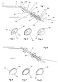
figure 1 shows in a very schematic view an A-pillar 20 of a vehicle and adjacent parts of thevehicle 10. The A-pillar 20 extends from itsfirst end 20a (its lower end) in the region of the rear end of thebonnet 16 to theroof 12 of the vehicle. The second end (upper end) of this A-pillar is denoted with 20b. When looking toFigure 1 and Figure 2 one can see that the A-pillar 20 consists in an upper region basically of two elements, namely theouter surface 24 of the vehicle, and anexpandable part 22 extending parallel to theouter surface 24. Additionally, aninner lining 26 which points towards the interior of the vehicle is provided. The expandable part is located between theouter surface 24 andinner lining 26. In the schematic representation offigure 2 there are rather large gaps between theexpandable part 22 and theouter surface 24 and theinner lining 26. This is drawn for overview reasons only, in practice theexpandable part 22 abuts at least the inner side of theouter surface 24 and can be welded to the same. One can see that theexpandable part 22, which is usually made of sheet metal, comprises afolding recess 23. One can also see fromFigure 1 that theexpandable part 22 extends basically along the complete length of the A-pillar 20, such that thefirst end 20a of the A-pillar and thefirst end 22a of theexpandable part 22 nearly coincide. The same applies for the second ends 20b, 22b of the A-pillar 20 and theexpandable part 22 respectively. Both ends of theexpandable part 22 are connected, especially welded, to structural parts of the vehicle. Here, thesecond end 22b of theexpandable part 22 is welded to theroof bar 14 and thefirst end 22a is welded to asupport structure 18 of a vehicle, which can for example be located near the wheel housing. Agas generator 40 serving as inflator and being provided near the lower end of the A-pillar, is in fluid connection to theexpandable part 22, such that the expandable part deploys on triggering of thegas generator 40. - A supporting
element 30 extends from thesupport structure 18 parallel to theexpandable part 22 between theouter surface 24 and theinner lining 26. This supportingelement 30 extends basically to a third of the length of the A-pillar 20 or less. In the first embodiment, this supportingelement 30 is comprised of tworods 32 being secured - for example welded - to thesupport structure 18 and aring 34 being secured to the front end of the rods. Thisring 34 forms the support section and the rods form the connecting section of this supportingelement 30. Therods 32 can be attached (for example welded) to the inside theouter surface 24 of the A-pillar or they can be an integral part thereof, so that therods 32 also reinforce the outer surface of the A-pillar. One can see fromFigure 3 that the diameter of thisring 34 is larger than the diameter of theexpandable part 22 when the expandable part is not deployed. -
Figures 5 to 8 show the situation after the gas generator has been triggered and the expandable part has been filled by gas and is thus expanded, such that the diameter of the A-pillar is enlarged to approximately 60 mm. Especially one can see inFigure 7 that theexpandable part 22 comes into contact with the ring 34 (although a small gap is drawn for the overview reasons). This means, that at least a part of the load which is applied to an upper section of the A-pillar 20 during an accident is directed into the supportingelement 30. This has two main advantages: On the one hand the maximum arm is shortened and on the other hand theexpandable part 22 has its maximum diameter at the point of the supporting section of the supporting element (ring 34). This is not the case at theends expandable part 22, since here the expandable part is closed and welded to other vehicle parts. Of course it is better that the maximum diameter of theexpandable part 22 can be used to transfer the force. -
Figures 8a and8b show aring 34 in a preferred shape. Here, thering 34 showsprotrusions 34a pointing towards the inside of thering 34. This enhances the form-fit that is being created at least in sections between theexpandable part 22 and thering 34 when theexpandable part 22 is deployed. -
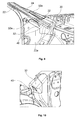
Figures 9 and 10 show a variation of the first embodiment of a supportingelement 30. Here, the support section is not formed as aring 34 encircling completely theexpandable part 22. The tworods 32 of the supportingelement 30 extending parallel to theexpandable part 22 end as the plate-shapedends 32a forming the supporting section. The distance of this plate-shaped ends 32a from theexpandable part 22 is such that they do not contact theexpandable part 22 when it is in non-deployed state and that theexpandable part 22 comes into contact with the plate-shaped ends when it is deployed. - Another difference is that the
gas generator 40 extends directly into theexpandable part 22 which saves space and makes the mounting easier. Here, the supportingelement 30 and theexpandable part 22 are directly connected to one another - usually welded - such that the supportingelement 30 has the further function to connect thefirst end 22a of theexpandable part 22 rigidly to a structural part of the vehicle. - The embodiment makes it possible that the gas generator is mounted after the assembly of the vehicle and especially after corrosion treatments of the car body have been carried out. This is advantageous, since the gas generator should not be exposed to the harsh environment during corrosion treatment.
- In a further variation of the first embodiment, the supporting element is a hollow cylinder extending from the support structure of the vehicle parallel to the expandable part.
- It is preferred to mount the gas generator in or at the lower end of the expandable part for several reasons. First, this position of the gas generator will not lead to a local hardness of the outer surface of the vehicle that is likely being hit by a pedestrian during an accident. Second, this low mounting position leads to a slim upper part of the A-pillar, which is desired for the better vision of the driver. Third, this low position of the gas generator makes the assembly easy.
-
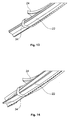
Figures 11 to 14 show a second embodiment of the invention.Figure 11 shows an A-pillar, a part of the roof-bar and a vehicle part adjacent to the lower end of the A-pillar in a 3-dimensional view. Here, the supporting element consists exclusively of its supporting section, namely aring 34 or sleeve being connected to theouter surface 24 of the vehicle. Thering 34 or sleeve does not need to be completely closed, but the outer surface and the ring or sleeve together encircle the expandable part. The geometry of thisring 34 or sleeve is as in the first embodiment: The inner diameter of thering 34 or sleeve is larger than the diameter of the non-deployedexpandable part 22 but equal of a little less than the diameter of the deployedexpandable part 22. This can be seen very good fromFigures 13 and 14 . So, a tight connection between the outer surface of the A-pillar and the deployedexpandable part 24 is generated making the A-pillar stiffer. -
Figure 12 is a more realistic view from what is shown infigure 2 and is a sectional view through an upper section of the A-pillar ofFigure 11 . One can see here that theexpandable part 22, which is welded from two sheets of metal having a thickness of approximately 1,5 mm is in sections welded to theouter surface 24 of the A-pillar of the vehicle and comprises afolding recess 23. Theinner lining 26 is not shown here. -
Figures 15 and 16 show a preferred possibility how the lower end of theexpandable part 22 can be sealed so that it is gas-tight and how thegas generator 40 can be connected to theexpandable part 22, namely via andend cap 50 which has two functions: First, it seals theexpandable part 22. For this purpose the end cap is welded to the expandable part via a weld seam 52 (Figure 16 ). Second, theend cap 50 serves for connecting thegas generator 40 to theexpandable part 22. Therefore, theend cap 50 comprises aflange 54 with a thread. Theend cap 50 can be welded to theexpandable part 22 prior to the corrosion treatment of the car body. Thegas generator 40 can conveniently be threaded to theend cap 50 at a late stage of the assembly, especially after the corrosion treatment. - As in the first embodiment, it is preferred to mount the gas generator in or at the lower end of the expandable part.
- The invention has been described in view of an A-pillar which is likely to be the most important application of the invention. But it needs to be emphasised that the application can be applied to all elongated structures of a vehicle that need to be stiff during an accident.
- It needs to be emphasised that the dimensions of the expandable part 22 (for example material thickness and diameter) depend on the vehicle model can differ from the examples given above.
-
- 10
- vehicle
- 12
- roof
- 14
- roof bar
- 16
- region of the bonnet
- 18
- support structure
- 20
- A-pillar
- 20a
- first end (lower end)
- 20b
- second end (upper end)
- 22
- expandable part
- 22a
- first end (lower end)
- 22b
- second end (upper end)
- 23
- folding recess
- 24
- outer surface
- 26
- inner lining
- 30
- supporting element
- 32
- rod
- 32a
- plate-shaped end
- 34
- ring
- 34a
- protrusion
- 40
- gas generator
- 50
- end cap
- 52
- weld seam
- 54
- flange with thread
Claims (14)
- Elongated structure for a vehicle (10) such as an A- B- or C-pillar (20) extending from a first (20a) end being connected to a first part of the vehicle to a second end (20b), said elongated structure comprising an expandable part (22) being in fluid connection to an inflator (40), wherein the diameter of the elongated structure enlarges at least in sections when the expandable part (22) is filled by gas of the inflator (40) and thus brought into a deployed state,
characterised in that additionally a supporting element (30) is present, said supporting element (30) comprising a supporting section being located near the expandable part (22) between the first end and the second end of the elongated structure and being fixed to a portion of the vehicle other than the expandable part, wherein the supporting section does not support the expandable part (22) when the expandable part (22) is in its non-deployed state. - Elongated structure according to claim 1, characterised in that the supporting element further comprises a connecting section being connected to the support section and being fixed to the vehicle near the first part of the vehicle.
- Elongated structure according to claim 1, characterised in that the supporting section is connected to an outer surface (24) of the elongated structure.
- Elongated structure according to claim 1 or claim 2, characterised in that the supporting section has at least one encircling section that encircles the expandable part (22).
- Elongated structure according to claim 4, characterised in that the inner diameter of the encircling section corresponds to the maximum diameter or less of the expandable part (22) at the position of the supporting section when the expandable part is in its deployed state, but is larger than the diameter of the expandable part (22) when the expandable part is in its non-deployed state.
- Elongated structure according to claim 4 or claim 5, characterised in that the encircling section has a ring- sleeve- or ribbon-shape.
- Elongated structure according to claim 4 or claim 5, characterised in that the encircling section is a hollow cylinder.
- Elongated structure according to one of the preceding claims, characterised in that the elongated structure is an A-pillar (20) of the vehicle extending from the first end upwardly.
- Elongated structure according to claim 8, characterised in that the supporting section is located in the lower third of the A-pillar (20).
- Elongated structure according to claim 7 or claim 8, characterised in that the inflator is located near the first end of the A-pillar.
- Elongated structure according to one of the preceding claims, characterised in that the inflator extends into the expandable part (22).
- Elongated structure according to one of the preceding claims, characterised in that the expandable part (22) has a folding recess (23).
- Elongated structure according to one of the preceding claim, characterised in that the thickness of the material of the expandable part is approximately 1,5 mm.
- Elongated structure according to one of the preceding claims, characterised in that the diameter of the expandable part (22) is approximately 60 mm in its deployed state.
Priority Applications (1)
| Application Number | Priority Date | Filing Date | Title |
|---|---|---|---|
| EP20110000460 EP2479070B1 (en) | 2011-01-21 | 2011-01-21 | Elongated structure for a vehicle |
Applications Claiming Priority (1)
| Application Number | Priority Date | Filing Date | Title |
|---|---|---|---|
| EP20110000460 EP2479070B1 (en) | 2011-01-21 | 2011-01-21 | Elongated structure for a vehicle |
Publications (2)
| Publication Number | Publication Date |
|---|---|
| EP2479070A1 true EP2479070A1 (en) | 2012-07-25 |
| EP2479070B1 EP2479070B1 (en) | 2014-08-20 |
Family
ID=44201283
Family Applications (1)
| Application Number | Title | Priority Date | Filing Date |
|---|---|---|---|
| EP20110000460 Not-in-force EP2479070B1 (en) | 2011-01-21 | 2011-01-21 | Elongated structure for a vehicle |
Country Status (1)
| Country | Link |
|---|---|
| EP (1) | EP2479070B1 (en) |
Citations (5)
| Publication number | Priority date | Publication date | Assignee | Title |
|---|---|---|---|---|
| EP1279564A1 (en) * | 2001-07-24 | 2003-01-29 | Benteler Automobiltechnik GmbH & Co. KG | Safety device for motor vehicles |
| JP2005035403A (en) * | 2003-07-15 | 2005-02-10 | Toyota Motor Corp | Vehicle impact resistant structure |
| WO2007059934A1 (en) | 2005-11-23 | 2007-05-31 | Autoliv Development Ab | Safety system |
| DE102007055623A1 (en) * | 2007-11-21 | 2009-06-04 | Autoliv Development Ab | Motor vehicle, has carrier part that is loaded in longitudinal direction during crash event, and airbag that expands and reinforces carrier part due to deployment of airbag caused by introduction of inflating gas, when airbag is activated |
| DE102009031118A1 (en) * | 2009-06-30 | 2011-03-03 | GM Global Technology Operations, Inc., Detroit | Safety device for motor vehicle, has rigid vehicle structure part, in which cavity is provided, and gas producer for blowing up vehicle structure part under enlargement of cavity during crash fall |
-
2011
- 2011-01-21 EP EP20110000460 patent/EP2479070B1/en not_active Not-in-force
Patent Citations (5)
| Publication number | Priority date | Publication date | Assignee | Title |
|---|---|---|---|---|
| EP1279564A1 (en) * | 2001-07-24 | 2003-01-29 | Benteler Automobiltechnik GmbH & Co. KG | Safety device for motor vehicles |
| JP2005035403A (en) * | 2003-07-15 | 2005-02-10 | Toyota Motor Corp | Vehicle impact resistant structure |
| WO2007059934A1 (en) | 2005-11-23 | 2007-05-31 | Autoliv Development Ab | Safety system |
| DE102007055623A1 (en) * | 2007-11-21 | 2009-06-04 | Autoliv Development Ab | Motor vehicle, has carrier part that is loaded in longitudinal direction during crash event, and airbag that expands and reinforces carrier part due to deployment of airbag caused by introduction of inflating gas, when airbag is activated |
| DE102009031118A1 (en) * | 2009-06-30 | 2011-03-03 | GM Global Technology Operations, Inc., Detroit | Safety device for motor vehicle, has rigid vehicle structure part, in which cavity is provided, and gas producer for blowing up vehicle structure part under enlargement of cavity during crash fall |
Also Published As
| Publication number | Publication date |
|---|---|
| EP2479070B1 (en) | 2014-08-20 |
Similar Documents
| Publication | Publication Date | Title |
|---|---|---|
| US6644725B2 (en) | Body pillar for a motor vehicle | |
| JP5550367B2 (en) | Vehicle roof column assembly | |
| US9630653B2 (en) | Vehicle body structure | |
| JP5239474B2 (en) | Automotive front structure | |
| CN104039634B (en) | Occupant protection structure and occupant protection method | |
| JP2014210548A (en) | Automobile passenger compartment front structure | |
| US20110156445A1 (en) | Motor vehicle featuring a structural car body column with a structural component and method for connecting a structural component of a structural car body column | |
| US9248862B1 (en) | Vehicle body structure | |
| JP5187813B2 (en) | Front pillar device | |
| EP2479070B1 (en) | Elongated structure for a vehicle | |
| EP2570308A1 (en) | Air-bag device | |
| JP4793540B2 (en) | Car steering device | |
| KR101320080B1 (en) | Safety system | |
| CN108146515B (en) | vehicle front structure | |
| EP2578455B1 (en) | Airbag system | |
| EP1770002B1 (en) | A-pillar for a vehicle | |
| JP2015016718A (en) | Car cabin front structure | |
| JP5471711B2 (en) | Upper body structure of the vehicle | |
| JP4715730B2 (en) | Knee airbag device with column | |
| EP2905185B1 (en) | Motor vehicle with an airbag between a wheel and the car body and airbag unit | |
| JP5817259B2 (en) | Automobile pedestrian protection structure | |
| JP4872958B2 (en) | Vehicle mounting structure for rear impact airbag device | |
| CN101879915B (en) | Vehicle roof support pillar assembly | |
| JP2011235813A (en) | Airbag device | |
| KR20020088746A (en) | Connection of roof panel and side out panel for vehicles |
Legal Events
| Date | Code | Title | Description |
|---|---|---|---|
| PUAI | Public reference made under article 153(3) epc to a published international application that has entered the european phase |
Free format text: ORIGINAL CODE: 0009012 |
|
| AK | Designated contracting states |
Kind code of ref document: A1 Designated state(s): AL AT BE BG CH CY CZ DE DK EE ES FI FR GB GR HR HU IE IS IT LI LT LU LV MC MK MT NL NO PL PT RO RS SE SI SK SM TR |
|
| AX | Request for extension of the european patent |
Extension state: BA ME |
|
| 17P | Request for examination filed |
Effective date: 20130123 |
|
| 17Q | First examination report despatched |
Effective date: 20130301 |
|
| 19U | Interruption of proceedings before grant |
Effective date: 20111219 |
|
| 19W | Proceedings resumed before grant after interruption of proceedings |
Effective date: 20140102 |
|
| RAP1 | Party data changed (applicant data changed or rights of an application transferred) |
Owner name: AUTOLIV DEVELOPMENT AB Owner name: NATIONAL ELECTRIC VEHICLE SWEDEN AB |
|
| GRAP | Despatch of communication of intention to grant a patent |
Free format text: ORIGINAL CODE: EPIDOSNIGR1 |
|
| INTG | Intention to grant announced |
Effective date: 20140307 |
|
| GRAS | Grant fee paid |
Free format text: ORIGINAL CODE: EPIDOSNIGR3 |
|
| GRAA | (expected) grant |
Free format text: ORIGINAL CODE: 0009210 |
|
| AK | Designated contracting states |
Kind code of ref document: B1 Designated state(s): AL AT BE BG CH CY CZ DE DK EE ES FI FR GB GR HR HU IE IS IT LI LT LU LV MC MK MT NL NO PL PT RO RS SE SI SK SM TR |
|
| REG | Reference to a national code |
Ref country code: GB Ref legal event code: FG4D |
|
| REG | Reference to a national code |
Ref country code: CH Ref legal event code: EP |
|
| REG | Reference to a national code |
Ref country code: AT Ref legal event code: REF Ref document number: 683258 Country of ref document: AT Kind code of ref document: T Effective date: 20140915 |
|
| REG | Reference to a national code |
Ref country code: IE Ref legal event code: FG4D |
|
| REG | Reference to a national code |
Ref country code: DE Ref legal event code: R096 Ref document number: 602011009202 Country of ref document: DE Effective date: 20141002 |
|
| REG | Reference to a national code |
Ref country code: AT Ref legal event code: MK05 Ref document number: 683258 Country of ref document: AT Kind code of ref document: T Effective date: 20140820 |
|
| REG | Reference to a national code |
Ref country code: NL Ref legal event code: VDEP Effective date: 20140820 |
|
| REG | Reference to a national code |
Ref country code: LT Ref legal event code: MG4D |
|
| PG25 | Lapsed in a contracting state [announced via postgrant information from national office to epo] |
Ref country code: PT Free format text: LAPSE BECAUSE OF FAILURE TO SUBMIT A TRANSLATION OF THE DESCRIPTION OR TO PAY THE FEE WITHIN THE PRESCRIBED TIME-LIMIT Effective date: 20141222 Ref country code: NO Free format text: LAPSE BECAUSE OF FAILURE TO SUBMIT A TRANSLATION OF THE DESCRIPTION OR TO PAY THE FEE WITHIN THE PRESCRIBED TIME-LIMIT Effective date: 20141120 Ref country code: SE Free format text: LAPSE BECAUSE OF FAILURE TO SUBMIT A TRANSLATION OF THE DESCRIPTION OR TO PAY THE FEE WITHIN THE PRESCRIBED TIME-LIMIT Effective date: 20140820 Ref country code: LT Free format text: LAPSE BECAUSE OF FAILURE TO SUBMIT A TRANSLATION OF THE DESCRIPTION OR TO PAY THE FEE WITHIN THE PRESCRIBED TIME-LIMIT Effective date: 20140820 Ref country code: GR Free format text: LAPSE BECAUSE OF FAILURE TO SUBMIT A TRANSLATION OF THE DESCRIPTION OR TO PAY THE FEE WITHIN THE PRESCRIBED TIME-LIMIT Effective date: 20141121 Ref country code: FI Free format text: LAPSE BECAUSE OF FAILURE TO SUBMIT A TRANSLATION OF THE DESCRIPTION OR TO PAY THE FEE WITHIN THE PRESCRIBED TIME-LIMIT Effective date: 20140820 Ref country code: ES Free format text: LAPSE BECAUSE OF FAILURE TO SUBMIT A TRANSLATION OF THE DESCRIPTION OR TO PAY THE FEE WITHIN THE PRESCRIBED TIME-LIMIT Effective date: 20140820 Ref country code: BG Free format text: LAPSE BECAUSE OF FAILURE TO SUBMIT A TRANSLATION OF THE DESCRIPTION OR TO PAY THE FEE WITHIN THE PRESCRIBED TIME-LIMIT Effective date: 20141120 |
|
| PG25 | Lapsed in a contracting state [announced via postgrant information from national office to epo] |
Ref country code: HR Free format text: LAPSE BECAUSE OF FAILURE TO SUBMIT A TRANSLATION OF THE DESCRIPTION OR TO PAY THE FEE WITHIN THE PRESCRIBED TIME-LIMIT Effective date: 20140820 Ref country code: AT Free format text: LAPSE BECAUSE OF FAILURE TO SUBMIT A TRANSLATION OF THE DESCRIPTION OR TO PAY THE FEE WITHIN THE PRESCRIBED TIME-LIMIT Effective date: 20140820 Ref country code: IS Free format text: LAPSE BECAUSE OF FAILURE TO SUBMIT A TRANSLATION OF THE DESCRIPTION OR TO PAY THE FEE WITHIN THE PRESCRIBED TIME-LIMIT Effective date: 20141220 Ref country code: RS Free format text: LAPSE BECAUSE OF FAILURE TO SUBMIT A TRANSLATION OF THE DESCRIPTION OR TO PAY THE FEE WITHIN THE PRESCRIBED TIME-LIMIT Effective date: 20140820 Ref country code: LV Free format text: LAPSE BECAUSE OF FAILURE TO SUBMIT A TRANSLATION OF THE DESCRIPTION OR TO PAY THE FEE WITHIN THE PRESCRIBED TIME-LIMIT Effective date: 20140820 |
|
| PG25 | Lapsed in a contracting state [announced via postgrant information from national office to epo] |
Ref country code: NL Free format text: LAPSE BECAUSE OF FAILURE TO SUBMIT A TRANSLATION OF THE DESCRIPTION OR TO PAY THE FEE WITHIN THE PRESCRIBED TIME-LIMIT Effective date: 20140820 |
|
| PG25 | Lapsed in a contracting state [announced via postgrant information from national office to epo] |
Ref country code: DK Free format text: LAPSE BECAUSE OF FAILURE TO SUBMIT A TRANSLATION OF THE DESCRIPTION OR TO PAY THE FEE WITHIN THE PRESCRIBED TIME-LIMIT Effective date: 20140820 Ref country code: RO Free format text: LAPSE BECAUSE OF FAILURE TO SUBMIT A TRANSLATION OF THE DESCRIPTION OR TO PAY THE FEE WITHIN THE PRESCRIBED TIME-LIMIT Effective date: 20140820 Ref country code: EE Free format text: LAPSE BECAUSE OF FAILURE TO SUBMIT A TRANSLATION OF THE DESCRIPTION OR TO PAY THE FEE WITHIN THE PRESCRIBED TIME-LIMIT Effective date: 20140820 Ref country code: SK Free format text: LAPSE BECAUSE OF FAILURE TO SUBMIT A TRANSLATION OF THE DESCRIPTION OR TO PAY THE FEE WITHIN THE PRESCRIBED TIME-LIMIT Effective date: 20140820 Ref country code: CZ Free format text: LAPSE BECAUSE OF FAILURE TO SUBMIT A TRANSLATION OF THE DESCRIPTION OR TO PAY THE FEE WITHIN THE PRESCRIBED TIME-LIMIT Effective date: 20140820 Ref country code: IT Free format text: LAPSE BECAUSE OF FAILURE TO SUBMIT A TRANSLATION OF THE DESCRIPTION OR TO PAY THE FEE WITHIN THE PRESCRIBED TIME-LIMIT Effective date: 20140820 |
|
| REG | Reference to a national code |
Ref country code: DE Ref legal event code: R097 Ref document number: 602011009202 Country of ref document: DE |
|
| PG25 | Lapsed in a contracting state [announced via postgrant information from national office to epo] |
Ref country code: PL Free format text: LAPSE BECAUSE OF FAILURE TO SUBMIT A TRANSLATION OF THE DESCRIPTION OR TO PAY THE FEE WITHIN THE PRESCRIBED TIME-LIMIT Effective date: 20140820 |
|
| PLBE | No opposition filed within time limit |
Free format text: ORIGINAL CODE: 0009261 |
|
| STAA | Information on the status of an ep patent application or granted ep patent |
Free format text: STATUS: NO OPPOSITION FILED WITHIN TIME LIMIT |
|
| PG25 | Lapsed in a contracting state [announced via postgrant information from national office to epo] |
Ref country code: BE Free format text: LAPSE BECAUSE OF NON-PAYMENT OF DUE FEES Effective date: 20150131 |
|
| 26N | No opposition filed |
Effective date: 20150521 |
|
| REG | Reference to a national code |
Ref country code: DE Ref legal event code: R119 Ref document number: 602011009202 Country of ref document: DE |
|
| REG | Reference to a national code |
Ref country code: CH Ref legal event code: PL |
|
| PG25 | Lapsed in a contracting state [announced via postgrant information from national office to epo] |
Ref country code: LU Free format text: LAPSE BECAUSE OF FAILURE TO SUBMIT A TRANSLATION OF THE DESCRIPTION OR TO PAY THE FEE WITHIN THE PRESCRIBED TIME-LIMIT Effective date: 20150121 |
|
| GBPC | Gb: european patent ceased through non-payment of renewal fee |
Effective date: 20150121 |
|
| PG25 | Lapsed in a contracting state [announced via postgrant information from national office to epo] |
Ref country code: MC Free format text: LAPSE BECAUSE OF FAILURE TO SUBMIT A TRANSLATION OF THE DESCRIPTION OR TO PAY THE FEE WITHIN THE PRESCRIBED TIME-LIMIT Effective date: 20140820 |
|
| PG25 | Lapsed in a contracting state [announced via postgrant information from national office to epo] |
Ref country code: CH Free format text: LAPSE BECAUSE OF NON-PAYMENT OF DUE FEES Effective date: 20150131 Ref country code: LI Free format text: LAPSE BECAUSE OF NON-PAYMENT OF DUE FEES Effective date: 20150131 Ref country code: DE Free format text: LAPSE BECAUSE OF NON-PAYMENT OF DUE FEES Effective date: 20150801 Ref country code: GB Free format text: LAPSE BECAUSE OF NON-PAYMENT OF DUE FEES Effective date: 20150121 |
|
| REG | Reference to a national code |
Ref country code: FR Ref legal event code: ST Effective date: 20150930 |
|
| REG | Reference to a national code |
Ref country code: IE Ref legal event code: MM4A |
|
| PG25 | Lapsed in a contracting state [announced via postgrant information from national office to epo] |
Ref country code: SI Free format text: LAPSE BECAUSE OF FAILURE TO SUBMIT A TRANSLATION OF THE DESCRIPTION OR TO PAY THE FEE WITHIN THE PRESCRIBED TIME-LIMIT Effective date: 20140820 Ref country code: FR Free format text: LAPSE BECAUSE OF NON-PAYMENT OF DUE FEES Effective date: 20150202 |
|
| PG25 | Lapsed in a contracting state [announced via postgrant information from national office to epo] |
Ref country code: IE Free format text: LAPSE BECAUSE OF NON-PAYMENT OF DUE FEES Effective date: 20150121 |
|
| PG25 | Lapsed in a contracting state [announced via postgrant information from national office to epo] |
Ref country code: BE Free format text: LAPSE BECAUSE OF FAILURE TO SUBMIT A TRANSLATION OF THE DESCRIPTION OR TO PAY THE FEE WITHIN THE PRESCRIBED TIME-LIMIT Effective date: 20140820 |
|
| PG25 | Lapsed in a contracting state [announced via postgrant information from national office to epo] |
Ref country code: MT Free format text: LAPSE BECAUSE OF FAILURE TO SUBMIT A TRANSLATION OF THE DESCRIPTION OR TO PAY THE FEE WITHIN THE PRESCRIBED TIME-LIMIT Effective date: 20140820 |
|
| PG25 | Lapsed in a contracting state [announced via postgrant information from national office to epo] |
Ref country code: HU Free format text: LAPSE BECAUSE OF FAILURE TO SUBMIT A TRANSLATION OF THE DESCRIPTION OR TO PAY THE FEE WITHIN THE PRESCRIBED TIME-LIMIT; INVALID AB INITIO Effective date: 20110121 Ref country code: SM Free format text: LAPSE BECAUSE OF FAILURE TO SUBMIT A TRANSLATION OF THE DESCRIPTION OR TO PAY THE FEE WITHIN THE PRESCRIBED TIME-LIMIT Effective date: 20140820 |
|
| PG25 | Lapsed in a contracting state [announced via postgrant information from national office to epo] |
Ref country code: CY Free format text: LAPSE BECAUSE OF FAILURE TO SUBMIT A TRANSLATION OF THE DESCRIPTION OR TO PAY THE FEE WITHIN THE PRESCRIBED TIME-LIMIT Effective date: 20140820 |
|
| PG25 | Lapsed in a contracting state [announced via postgrant information from national office to epo] |
Ref country code: TR Free format text: LAPSE BECAUSE OF FAILURE TO SUBMIT A TRANSLATION OF THE DESCRIPTION OR TO PAY THE FEE WITHIN THE PRESCRIBED TIME-LIMIT Effective date: 20140820 |
|
| PG25 | Lapsed in a contracting state [announced via postgrant information from national office to epo] |
Ref country code: MK Free format text: LAPSE BECAUSE OF FAILURE TO SUBMIT A TRANSLATION OF THE DESCRIPTION OR TO PAY THE FEE WITHIN THE PRESCRIBED TIME-LIMIT Effective date: 20140820 |
|
| PG25 | Lapsed in a contracting state [announced via postgrant information from national office to epo] |
Ref country code: AL Free format text: LAPSE BECAUSE OF FAILURE TO SUBMIT A TRANSLATION OF THE DESCRIPTION OR TO PAY THE FEE WITHIN THE PRESCRIBED TIME-LIMIT Effective date: 20140820 |