EP2479010A1 - Cutting device - Google Patents
Cutting device Download PDFInfo
- Publication number
- EP2479010A1 EP2479010A1 EP10817068A EP10817068A EP2479010A1 EP 2479010 A1 EP2479010 A1 EP 2479010A1 EP 10817068 A EP10817068 A EP 10817068A EP 10817068 A EP10817068 A EP 10817068A EP 2479010 A1 EP2479010 A1 EP 2479010A1
- Authority
- EP
- European Patent Office
- Prior art keywords
- blade
- cutting
- roll
- anvil roll
- receiving blade
- Prior art date
- Legal status (The legal status is an assumption and is not a legal conclusion. Google has not performed a legal analysis and makes no representation as to the accuracy of the status listed.)
- Withdrawn
Links
Images


Classifications
-
- B—PERFORMING OPERATIONS; TRANSPORTING
- B26—HAND CUTTING TOOLS; CUTTING; SEVERING
- B26D—CUTTING; DETAILS COMMON TO MACHINES FOR PERFORATING, PUNCHING, CUTTING-OUT, STAMPING-OUT OR SEVERING
- B26D1/00—Cutting through work characterised by the nature or movement of the cutting member or particular materials not otherwise provided for; Apparatus or machines therefor; Cutting members therefor
- B26D1/56—Cutting through work characterised by the nature or movement of the cutting member or particular materials not otherwise provided for; Apparatus or machines therefor; Cutting members therefor involving a cutting member which travels with the work otherwise than in the direction of the cut, i.e. flying cutter
- B26D1/62—Cutting through work characterised by the nature or movement of the cutting member or particular materials not otherwise provided for; Apparatus or machines therefor; Cutting members therefor involving a cutting member which travels with the work otherwise than in the direction of the cut, i.e. flying cutter and is rotating about an axis parallel to the line of cut, e.g. mounted on a rotary cylinder
-
- B—PERFORMING OPERATIONS; TRANSPORTING
- B26—HAND CUTTING TOOLS; CUTTING; SEVERING
- B26D—CUTTING; DETAILS COMMON TO MACHINES FOR PERFORATING, PUNCHING, CUTTING-OUT, STAMPING-OUT OR SEVERING
- B26D1/00—Cutting through work characterised by the nature or movement of the cutting member or particular materials not otherwise provided for; Apparatus or machines therefor; Cutting members therefor
- B26D1/01—Cutting through work characterised by the nature or movement of the cutting member or particular materials not otherwise provided for; Apparatus or machines therefor; Cutting members therefor involving a cutting member which does not travel with the work
- B26D1/12—Cutting through work characterised by the nature or movement of the cutting member or particular materials not otherwise provided for; Apparatus or machines therefor; Cutting members therefor involving a cutting member which does not travel with the work having a cutting member moving about an axis
- B26D1/25—Cutting through work characterised by the nature or movement of the cutting member or particular materials not otherwise provided for; Apparatus or machines therefor; Cutting members therefor involving a cutting member which does not travel with the work having a cutting member moving about an axis with a non-circular cutting member
- B26D1/34—Cutting through work characterised by the nature or movement of the cutting member or particular materials not otherwise provided for; Apparatus or machines therefor; Cutting members therefor involving a cutting member which does not travel with the work having a cutting member moving about an axis with a non-circular cutting member moving about an axis parallel to the line of cut
- B26D1/36—Cutting through work characterised by the nature or movement of the cutting member or particular materials not otherwise provided for; Apparatus or machines therefor; Cutting members therefor involving a cutting member which does not travel with the work having a cutting member moving about an axis with a non-circular cutting member moving about an axis parallel to the line of cut and rotating continuously in one direction during cutting, e.g. mounted on a rotary cylinder
-
- B—PERFORMING OPERATIONS; TRANSPORTING
- B26—HAND CUTTING TOOLS; CUTTING; SEVERING
- B26D—CUTTING; DETAILS COMMON TO MACHINES FOR PERFORATING, PUNCHING, CUTTING-OUT, STAMPING-OUT OR SEVERING
- B26D1/00—Cutting through work characterised by the nature or movement of the cutting member or particular materials not otherwise provided for; Apparatus or machines therefor; Cutting members therefor
- B26D1/01—Cutting through work characterised by the nature or movement of the cutting member or particular materials not otherwise provided for; Apparatus or machines therefor; Cutting members therefor involving a cutting member which does not travel with the work
- B26D1/12—Cutting through work characterised by the nature or movement of the cutting member or particular materials not otherwise provided for; Apparatus or machines therefor; Cutting members therefor involving a cutting member which does not travel with the work having a cutting member moving about an axis
- B26D1/25—Cutting through work characterised by the nature or movement of the cutting member or particular materials not otherwise provided for; Apparatus or machines therefor; Cutting members therefor involving a cutting member which does not travel with the work having a cutting member moving about an axis with a non-circular cutting member
- B26D1/34—Cutting through work characterised by the nature or movement of the cutting member or particular materials not otherwise provided for; Apparatus or machines therefor; Cutting members therefor involving a cutting member which does not travel with the work having a cutting member moving about an axis with a non-circular cutting member moving about an axis parallel to the line of cut
- B26D1/40—Cutting through work characterised by the nature or movement of the cutting member or particular materials not otherwise provided for; Apparatus or machines therefor; Cutting members therefor involving a cutting member which does not travel with the work having a cutting member moving about an axis with a non-circular cutting member moving about an axis parallel to the line of cut and coacting with a rotary member
-
- B—PERFORMING OPERATIONS; TRANSPORTING
- B26—HAND CUTTING TOOLS; CUTTING; SEVERING
- B26D—CUTTING; DETAILS COMMON TO MACHINES FOR PERFORATING, PUNCHING, CUTTING-OUT, STAMPING-OUT OR SEVERING
- B26D1/00—Cutting through work characterised by the nature or movement of the cutting member or particular materials not otherwise provided for; Apparatus or machines therefor; Cutting members therefor
- B26D1/01—Cutting through work characterised by the nature or movement of the cutting member or particular materials not otherwise provided for; Apparatus or machines therefor; Cutting members therefor involving a cutting member which does not travel with the work
- B26D1/12—Cutting through work characterised by the nature or movement of the cutting member or particular materials not otherwise provided for; Apparatus or machines therefor; Cutting members therefor involving a cutting member which does not travel with the work having a cutting member moving about an axis
- B26D1/25—Cutting through work characterised by the nature or movement of the cutting member or particular materials not otherwise provided for; Apparatus or machines therefor; Cutting members therefor involving a cutting member which does not travel with the work having a cutting member moving about an axis with a non-circular cutting member
- B26D1/34—Cutting through work characterised by the nature or movement of the cutting member or particular materials not otherwise provided for; Apparatus or machines therefor; Cutting members therefor involving a cutting member which does not travel with the work having a cutting member moving about an axis with a non-circular cutting member moving about an axis parallel to the line of cut
- B26D1/40—Cutting through work characterised by the nature or movement of the cutting member or particular materials not otherwise provided for; Apparatus or machines therefor; Cutting members therefor involving a cutting member which does not travel with the work having a cutting member moving about an axis with a non-circular cutting member moving about an axis parallel to the line of cut and coacting with a rotary member
- B26D1/405—Cutting through work characterised by the nature or movement of the cutting member or particular materials not otherwise provided for; Apparatus or machines therefor; Cutting members therefor involving a cutting member which does not travel with the work having a cutting member moving about an axis with a non-circular cutting member moving about an axis parallel to the line of cut and coacting with a rotary member for thin material, e.g. for sheets, strips or the like
-
- B—PERFORMING OPERATIONS; TRANSPORTING
- B26—HAND CUTTING TOOLS; CUTTING; SEVERING
- B26D—CUTTING; DETAILS COMMON TO MACHINES FOR PERFORATING, PUNCHING, CUTTING-OUT, STAMPING-OUT OR SEVERING
- B26D7/00—Details of apparatus for cutting, cutting-out, stamping-out, punching, perforating, or severing by means other than cutting
- B26D7/20—Cutting beds
- B26D7/204—Anvil rollers
-
- B—PERFORMING OPERATIONS; TRANSPORTING
- B26—HAND CUTTING TOOLS; CUTTING; SEVERING
- B26D—CUTTING; DETAILS COMMON TO MACHINES FOR PERFORATING, PUNCHING, CUTTING-OUT, STAMPING-OUT OR SEVERING
- B26D7/00—Details of apparatus for cutting, cutting-out, stamping-out, punching, perforating, or severing by means other than cutting
- B26D7/26—Means for mounting or adjusting the cutting member; Means for adjusting the stroke of the cutting member
- B26D7/2614—Means for mounting the cutting member
-
- B—PERFORMING OPERATIONS; TRANSPORTING
- B26—HAND CUTTING TOOLS; CUTTING; SEVERING
- B26D—CUTTING; DETAILS COMMON TO MACHINES FOR PERFORATING, PUNCHING, CUTTING-OUT, STAMPING-OUT OR SEVERING
- B26D7/00—Details of apparatus for cutting, cutting-out, stamping-out, punching, perforating, or severing by means other than cutting
- B26D7/26—Means for mounting or adjusting the cutting member; Means for adjusting the stroke of the cutting member
- B26D2007/2685—Means for mounting or adjusting the cutting member; Means for adjusting the stroke of the cutting member flexible mounting means
-
- Y—GENERAL TAGGING OF NEW TECHNOLOGICAL DEVELOPMENTS; GENERAL TAGGING OF CROSS-SECTIONAL TECHNOLOGIES SPANNING OVER SEVERAL SECTIONS OF THE IPC; TECHNICAL SUBJECTS COVERED BY FORMER USPC CROSS-REFERENCE ART COLLECTIONS [XRACs] AND DIGESTS
- Y10—TECHNICAL SUBJECTS COVERED BY FORMER USPC
- Y10T—TECHNICAL SUBJECTS COVERED BY FORMER US CLASSIFICATION
- Y10T83/00—Cutting
- Y10T83/465—Cutting motion of tool has component in direction of moving work
- Y10T83/4766—Orbital motion of cutting blade
- Y10T83/4795—Rotary tool
- Y10T83/483—With cooperating rotary cutter or backup
- Y10T83/4844—Resiliently urged cutter or anvil member
Definitions
- the present invention relates to a cutting system.
- a cutting system provided with a cutter roll and an anvil roll rotating in opposite directions to each other about substantially parallel axes of rotation, the cutting system cutting a material to be cut which is fed between these cutter roll and anvil roll, by a cutting blade carried on the cutter roll.
- the cutter roll will gradually expand due to heat so the clearance between the cutting blade and circumferential surface of the anvil roll is liable to become smaller. As a result, the cutting blade is liable to become remarkably worn or chipped and the lifetime of the cutting blade is liable to become remarkably shorter. On the other hand, if the clearance is set large in advance, the material to be cut is liable not to be able to be reliably cut.
- PLT 1 Japanese Unexamined Patent Publication No. 2001-38675
- a cutting system provided with a cutter roll and an anvil roll rotating in opposite directions to each other about substantially parallel axes of rotation, these cutter roll and anvil roll respectively carrying a cutting blade and receiving blade, the cutting system cutting a material to be cut which is fed between these cutter roll and anvil roll, by the facing cutting blade and receiving blade, wherein the receiving blade can elastically displace in a radial direction of the anvil roll.
- a cutting system provided with a cutter roll and an anvil roll rotating in opposite directions to each other about substantially parallel axes of rotation, the cutting system cutting a material to be cut which is fed between these cutter roll and anvil roll, by a cutting blade carried on the cutter roll, wherein the cutting blade can elastically displace in a radial direction of the cutter roll.
- FIG. 1 shows a cutting system of an embodiment according to the present invention.
- This cutting system 1 is for cutting a material to be cut having a belt shape into a plurality of cut parts.
- the material to be cut is for example comprised of at least one member selected from a nonwoven fabric, paper, fiber aggregate, and plastic film.
- a fiber aggregate is comprised of natural fibers or synthetic fibers and includes tows, card webs, sliders, etc. where the fibers are not bonded with each other.
- the cutting system 1 is provided with a cutter roll 2 and anvil roll 3 arranged aligned in the vertical direction. These cutter roll 2 and anvil roll 3 are respectively supported at a frame 4 to be able to rotate about substantially parallel direction axes of rotation L and M, therefore are designed to be able to rotate about the substantially parallel direction axes of rotation L and M.
- the cutter roll 2 is provided with a roll body 2a and shafts 2b.
- the shafts 2b are supported at the frame 4 through bearings 4a.
- the anvil roll 3 is also provided with a roll body 3a and shafts 3b.
- the shafts 3b are supported at the frame 4 through bearings 4b.
- the anvil roll 3 is designed to be able to displace together with the bearings 4b in the vertical direction. Therefore, the distance D between axes of the cutter roll 2 and anvil roll 3 can be adjusted. In this case, the anvil roll 3 is displaced in the vertical direction by elevation devices fastened to the bearings 4b such as pneumatic or oil hydraulic cylinders 4c.
- the shafts 2b and 3b have gears 2c and 3c attached to them and engaging with each other.
- the cutter roll 2 and anvil roll 3 are rotated in opposite directions synchronized with each other by these gears 2c and 3c. Note that, in the cutting system shown in FIG. 1 , drive devices (not shown) are connected to the shafts 2b of the cutter roll 2.
- flanges or side rings 2d are provided at the two sides of the roll body 2a of the cutter roll 2. These flanges 2d contact the circumferential surface of the roll body 3a of the anvil roll 3.
- a cutting blade 2e is carried, while at the roll body 3a of the anvil roll 3, a receiving blade 3e is carried.
- the roll body 2a of the cutter roll 2 is formed with a recessed groove 2f extending in the axial L-L direction.
- the cutting blade 2e is fastened to the inner wall surface of this recessed groove 2f by washers 2g and bolts 2h.
- the cutting blade 2e is comprised of a flat blade extending in the axial L-L direction of the cutter roll 2 and is fastened so as to project out in the radial direction of the cutter roll 2.
- the cutting blade 2e can also be comprised of another blade.
- the roll body 3a of the anvil roll 3 is formed at the circumferential surface with a recessed groove 3f extending in the axial M-M direction.
- a flat receiving blade 3e is held in the recessed groove 3f.
- an elastic member 3g is interposed between the receiving blade 3e and the recessed groove 3f.
- the elastic member 3g is housed together with the receiving blade 3e in the recessed groove 3f.
- the receiving blade 3e is supported at the anvil roll 3 through the elastic member 3g.
- a pair of limit members 3h are fastened by fasteners 3i to the roll body 3a of the anvil roll 3.
- the elastic member 3g is housed in the recessed groove 3f in a compressed state and biases the receiving blade 3e outward in the radial direction. In this case, the receiving blade 3e strikes the limit members 3h, therefore displacement of the receiving blade 3e outward in the radial direction is limited.
- the elastic member 3g When the receiving blade 3e is acted upon by force inward in the radial direction, the elastic member 3g is compressed and the receiving blade 3e separates from the limit member 3h and displaces inward in the radial direction. When the receiving blade 3e is no longer acted upon by force, the elastic member 3g springs back and the receiving blade 3e displaces outward in the radial direction and strikes the limit members 3h. In this way, the receiving blade 3e is designed to be able to elastically displace in the radial direction of the anvil roll 3.
- the cutting blade 2e is made from high strength steel having an HRC hardness of 60°
- the receiving blade 3e is made from carbon steel having an HRC hardness of 52.5°
- the elastic material 3g is made from synthetic rubber or natural rubber such as urethane rubber having a hardness of HS90°.
- the cutting blade 2e is preferably harder than the receiving blade 3e, but this is not essential.
- the clearance between the cutting blade 2e and the receiving blade 3e is made to become a negative value by adjustment of the distance D between axes ( FIG. 1 ) in advance.
- the positional relationship between the cutting blade 2e and the receiving blade 3e is set in advance so that when the cutting blade 2e and receiving blade 3e face each other, the cutting blade 2e will strike the receiving blade 3e.
- the material to be cut is transported by a conveyor (not shown) in the substantially horizontal direction and fed into the cutting system 1, specifically, between the cutter roll 2 and the anvil roll 3.
- a conveyor not shown
- the cutter roll 2 and the anvil roll 3 rotate and the cutting blade 2e and receiving blade 3e face each other, these cutting blade 2e and receiving blade 3e cut the material to be cut.
- the cut material is then transported further by the conveyor (not shown) in the substantially horizontal direction.
- the edge 2et of the cutting blade 2e reliably crosses the material to be cut to reach the receiving blade 3e, therefore can cut the material to be cut well.
- the receiving blade 3e displaces inward in the radial direction of the anvil roll 3 whereby the impact force acting on the cutting blade 2e is absorbed. Therefore, even when setting the clearance to a negative value, wear and chipping of the cutting blade 2e are suppressed and the lifetime of the cutting blade 2e is prolonged.
- the edge 2et of the cutting blade 2e can be made sharper and therefore the material to be cut can be cut better.
- the material to be cut will be crushed by the cutting blade 2e while being cut and press bonding or heat bonding of the material to be cut is liable to occur near the cut surface.
- the material to be cut includes tow etc. where the fibers are not bonded with each other, the press bonding or heat bonding is liable to detract from the fluffy state of the material to be cut.
- the material to be cut will be incompletely cut and the material to be cut is liable to be left with uncut pieces etc.
- the edge 3et of the cutting blade 2e can be made sharp, so the material to be cut can be cut well. That is, it is possible to suppress press bonding and melt bonding from occurring around the cut surfaces and possible to maintain a fluffy state of the material to be cut.
- the polishing applied to the edge 2et of the cutting blade 2e in advance or flexing of the cutting blade 2e itself will result in unevenness of the edge 2et in the longitudinal direction.
- the cutting blade 2e was cylindrically polished. In this regard, if cylindrically polishing it, the width of the edge 2et of the cutting blade 2e is liable to become greater.
- the receiving blade 3e elastically deforms in the radial direction, so the effects of unevenness of the edge 2et are absorbed. As a result, cylindrical polishing of the cutting blade 2e becomes unnecessary and therefore the cutting blade 2e can be maintained sharp.
- FIG. 5 shows another embodiment according to the present invention.
- a pair of receiving grooves 3j extending in the axial M-M direction are formed at the two sides of the recessed groove 3f in the circumferential direction of the anvil roll 3.
- the two ends 3ee of the receiving blade 3e in the circumferential direction of the anvil roll 3 are housed in the receiving grooves 3j and are fastened by the limit members 3h. That is, the receiving blade 3e is supported at the anvil roll 3 at the two ends in the circumferential direction of the anvil roll 3.
- the receiving blade 3e is supported at its two ends. However, the receiving blade 3e may also be supported at one end.
- FIG. 6 shows still another embodiment of the present invention.
- a recessed groove 2i is formed extending in the blade axial L-L direction in the circumferential surface of the roll body 2a of the cutter roll 2.
- the base 3eb of the cutting blade 2e is housed inside the recessed groove 2i.
- a compressed state elastic member 3j is interposed between the cutting blade 2e and the recessed groove 2i.
- the elastic member 2j is housed together with the cutting blade 2e in the recessed groove 2i.
- the cutting blade 2e is supported at the cutter roll 2 through the elastic member 2j.
- a pair of limit members 2k are affixed by fasteners 2m to the roll body 2a of the cutter roll 2 and limit displacement of the cutting blade 2e outward in the radial direction.
- the elastic member 2j is compressed and the cutting blade 2e separates from the limit members 2k and displaces inward in the radial direction.
- the elastic member 2j springs back and the cutting blade 2e displaces outward in the radial direction to strike the limit members 2k. In this way, the cutting blade 2e can elastically displace in the radial direction of the cutter roll 2. Even if so designed, it is possible to secure good cutting while extending the lifetime of the cutting blade 2e.
- the receiving blade 3e may be able to displace in the radial direction of the anvil roll 3 or not be able to displace there.
- the receiving blade 3e may be omitted and the circumferential surface of the roll body 3a of the anvil roll 3 may act as the receiving blade.
Landscapes
- Life Sciences & Earth Sciences (AREA)
- Forests & Forestry (AREA)
- Engineering & Computer Science (AREA)
- Mechanical Engineering (AREA)
- Perforating, Stamping-Out Or Severing By Means Other Than Cutting (AREA)
- Nonmetal Cutting Devices (AREA)
Abstract
Description
- The present invention relates to a cutting system.
- Known in the past has been a cutting system provided with a cutter roll and an anvil roll rotating in opposite directions to each other about substantially parallel axes of rotation, the cutting system cutting a material to be cut which is fed between these cutter roll and anvil roll, by a cutting blade carried on the cutter roll.
- In this regard, if the cutting system is continuously operated over a long period of time, the cutter roll will gradually expand due to heat so the clearance between the cutting blade and circumferential surface of the anvil roll is liable to become smaller. As a result, the cutting blade is liable to become remarkably worn or chipped and the lifetime of the cutting blade is liable to become remarkably shorter. On the other hand, if the clearance is set large in advance, the material to be cut is liable not to be able to be reliably cut.
- Therefore, there is known a cutting system designed to run coolant through the cutter roll so as to suppress heat expansion of the cutter roll (see PLT 1).
- PLT 1: Japanese Unexamined Patent Publication No.
2001-38675 - However, in the cutting system of
PLT 1, the configuration is liable to become complicated and the running costs to become high. Further, vibration, bending, etc. of the cutter roll and anvil roll result in constant fluctuation of the clearance, so even if suppressing heat expansion of the cutter roll, it would be difficult to sufficiently suppress wear and chipping of the cutting blade. - According to one aspect of the present invention, there is provided a cutting system provided with a cutter roll and an anvil roll rotating in opposite directions to each other about substantially parallel axes of rotation, these cutter roll and anvil roll respectively carrying a cutting blade and receiving blade, the cutting system cutting a material to be cut which is fed between these cutter roll and anvil roll, by the facing cutting blade and receiving blade, wherein the receiving blade can elastically displace in a radial direction of the anvil roll.
- Further, according to another aspect of the present invention, there is provided a cutting system provided with a cutter roll and an anvil roll rotating in opposite directions to each other about substantially parallel axes of rotation, the cutting system cutting a material to be cut which is fed between these cutter roll and anvil roll, by a cutting blade carried on the cutter roll, wherein the cutting blade can elastically displace in a radial direction of the cutter roll.
- It is possible to secure good cutting of the material to be cut while extending the lifetime of the cutting blade by a simple configuration.
-
-
FIG. 1 is an overall view of a cutting system. -
FIG. 2 is a cross-sectional view along the line II-II ofFIG. 1 . -
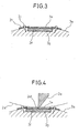
FIG. 3 is an enlarged view of a part III ofFIG. 2 . -
FIG. 4 is a cross-sectional view similar toFIG. 3 for explaining an embodiment according to the present invention. -
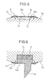
FIG. 5 is a view showing another embodiment according to the present invention. -
FIG. 6 is a view showing still another embodiment according to the present invention. -
FIG. 1 shows a cutting system of an embodiment according to the present invention. Thiscutting system 1 is for cutting a material to be cut having a belt shape into a plurality of cut parts. Here, the material to be cut is for example comprised of at least one member selected from a nonwoven fabric, paper, fiber aggregate, and plastic film. A fiber aggregate is comprised of natural fibers or synthetic fibers and includes tows, card webs, sliders, etc. where the fibers are not bonded with each other. - Referring to
FIG. 1 , thecutting system 1 is provided with acutter roll 2 andanvil roll 3 arranged aligned in the vertical direction. Thesecutter roll 2 andanvil roll 3 are respectively supported at aframe 4 to be able to rotate about substantially parallel direction axes of rotation L and M, therefore are designed to be able to rotate about the substantially parallel direction axes of rotation L and M. - The
cutter roll 2 is provided with aroll body 2a andshafts 2b. Theshafts 2b are supported at theframe 4 throughbearings 4a. Theanvil roll 3 is also provided with aroll body 3a andshafts 3b. Theshafts 3b are supported at theframe 4 throughbearings 4b. - Here, the
anvil roll 3 is designed to be able to displace together with thebearings 4b in the vertical direction. Therefore, the distance D between axes of thecutter roll 2 andanvil roll 3 can be adjusted. In this case, theanvil roll 3 is displaced in the vertical direction by elevation devices fastened to thebearings 4b such as pneumatic or oil hydraulic cylinders 4c. - The
shafts gears cutter roll 2 andanvil roll 3 are rotated in opposite directions synchronized with each other by thesegears FIG. 1 , drive devices (not shown) are connected to theshafts 2b of thecutter roll 2. - Furthermore, referring to
FIG. 1 , flanges orside rings 2d are provided at the two sides of theroll body 2a of thecutter roll 2. Theseflanges 2d contact the circumferential surface of theroll body 3a of theanvil roll 3. - Further, at the
roll body 2a of thecutter roll 2, acutting blade 2e is carried, while at theroll body 3a of theanvil roll 3, areceiving blade 3e is carried. - That is, as will be understood from
FIG. 2 as well, theroll body 2a of thecutter roll 2 is formed with arecessed groove 2f extending in the axial L-L direction. Thecutting blade 2e is fastened to the inner wall surface of thisrecessed groove 2f by washers 2g andbolts 2h. In the cutting system shown inFIG. 1 , thecutting blade 2e is comprised of a flat blade extending in the axial L-L direction of thecutter roll 2 and is fastened so as to project out in the radial direction of thecutter roll 2. Naturally, thecutting blade 2e can also be comprised of another blade. - Further, as shown in
FIG. 3 as well, theroll body 3a of theanvil roll 3 is formed at the circumferential surface with arecessed groove 3f extending in the axial M-M direction. A flat receivingblade 3e is held in therecessed groove 3f. - In this case, an
elastic member 3g is interposed between thereceiving blade 3e and therecessed groove 3f. Theelastic member 3g is housed together with thereceiving blade 3e in therecessed groove 3f. As a result, thereceiving blade 3e is supported at theanvil roll 3 through theelastic member 3g. - At the two sides of the
recessed groove 3f in the circumferential direction of theanvil roll 3, a pair oflimit members 3h are fastened by fasteners 3i to theroll body 3a of theanvil roll 3. Theelastic member 3g is housed in therecessed groove 3f in a compressed state and biases the receivingblade 3e outward in the radial direction. In this case, thereceiving blade 3e strikes thelimit members 3h, therefore displacement of the receivingblade 3e outward in the radial direction is limited. - When the
receiving blade 3e is acted upon by force inward in the radial direction, theelastic member 3g is compressed and thereceiving blade 3e separates from thelimit member 3h and displaces inward in the radial direction. When thereceiving blade 3e is no longer acted upon by force, theelastic member 3g springs back and thereceiving blade 3e displaces outward in the radial direction and strikes thelimit members 3h. In this way, thereceiving blade 3e is designed to be able to elastically displace in the radial direction of theanvil roll 3. - Here, in the cutting system shown in
FIG. 1 , thecutting blade 2e is made from high strength steel having an HRC hardness of 60°, the receivingblade 3e is made from carbon steel having an HRC hardness of 52.5°, and theelastic material 3g is made from synthetic rubber or natural rubber such as urethane rubber having a hardness of HS90°. Note that thecutting blade 2e is preferably harder than thereceiving blade 3e, but this is not essential. - Furthermore, in the cutting system shown in
FIG. 1 , the clearance between thecutting blade 2e and thereceiving blade 3e is made to become a negative value by adjustment of the distance D between axes (FIG. 1 ) in advance. In other words, the positional relationship between thecutting blade 2e and thereceiving blade 3e is set in advance so that when thecutting blade 2e and receivingblade 3e face each other, thecutting blade 2e will strike thereceiving blade 3e. - Now then, the material to be cut is transported by a conveyor (not shown) in the substantially horizontal direction and fed into the
cutting system 1, specifically, between thecutter roll 2 and theanvil roll 3. When thecutter roll 2 and theanvil roll 3 rotate and thecutting blade 2e and receivingblade 3e face each other, thesecutting blade 2e and receivingblade 3e cut the material to be cut. The cut material is then transported further by the conveyor (not shown) in the substantially horizontal direction. - In this case, in the cutting system shown in
FIG. 1 , since the clearance is set to a negative value, the edge 2et of thecutting blade 2e reliably crosses the material to be cut to reach thereceiving blade 3e, therefore can cut the material to be cut well. - Here, as shown in
FIG. 4 , when thecutting blade 2e strikes thereceiving blade 3e, thereceiving blade 3e displaces inward in the radial direction of theanvil roll 3 whereby the impact force acting on thecutting blade 2e is absorbed. Therefore, even when setting the clearance to a negative value, wear and chipping of thecutting blade 2e are suppressed and the lifetime of thecutting blade 2e is prolonged. - Further, when heat expansion, vibration, etc. of the
cutter roll 2,anvil roll 3,cutting blade 2e, or receivingblade 3e causes the clearance to fluctuate, the amount of displacement of thereceiving blade 3e in the radial direction will fluctuate and therefore the impact force acting on thecutting blade 2e will be absorbed. Therefore, in this case as well, good cutting of the material to be cut is secured while the lifetime of thecutting blade 2e is prolonged. - Furthermore, since wear and chipping of the
cutting blade 2e are suppressed, the edge 2et of thecutting blade 2e can be made sharper and therefore the material to be cut can be cut better. - In this regard, if the width of the edge 2et of the
cutting blade 2e is large, that is, the edge 2et is dull, the material to be cut will be crushed by thecutting blade 2e while being cut and press bonding or heat bonding of the material to be cut is liable to occur near the cut surface. When the material to be cut includes tow etc. where the fibers are not bonded with each other, the press bonding or heat bonding is liable to detract from the fluffy state of the material to be cut. Alternatively, the material to be cut will be incompletely cut and the material to be cut is liable to be left with uncut pieces etc. - As opposed to this, in this embodiment of the present invention, the edge 3et of the
cutting blade 2e can be made sharp, so the material to be cut can be cut well. That is, it is possible to suppress press bonding and melt bonding from occurring around the cut surfaces and possible to maintain a fluffy state of the material to be cut. - Further, sometimes the polishing applied to the edge 2et of the
cutting blade 2e in advance or flexing of thecutting blade 2e itself will result in unevenness of the edge 2et in the longitudinal direction. In the past, to reduce this unevenness, thecutting blade 2e was cylindrically polished. In this regard, if cylindrically polishing it, the width of the edge 2et of thecutting blade 2e is liable to become greater. - As opposed to this, in this embodiment of the present invention, the
receiving blade 3e elastically deforms in the radial direction, so the effects of unevenness of the edge 2et are absorbed. As a result, cylindrical polishing of thecutting blade 2e becomes unnecessary and therefore thecutting blade 2e can be maintained sharp. -
FIG. 5 shows another embodiment according to the present invention. - Referring to
FIG. 5 , at the two sides of the recessedgroove 3f in the circumferential direction of theanvil roll 3, a pair of receiving grooves 3j extending in the axial M-M direction are formed. The two ends 3ee of thereceiving blade 3e in the circumferential direction of theanvil roll 3 are housed in the receiving grooves 3j and are fastened by thelimit members 3h. That is, thereceiving blade 3e is supported at theanvil roll 3 at the two ends in the circumferential direction of theanvil roll 3. - In the example shown in
FIG. 5 , when thecutting blade 2e strikes thereceiving blade 3e, the center 3ec of thereceiving blade 3e flexes inward in the radial direction. As a result, the impact force acting on thecutting blade 2e can be absorbed. - Note that, in the example shown in
FIG. 5 , thereceiving blade 3e is supported at its two ends. However, thereceiving blade 3e may also be supported at one end. -
FIG. 6 shows still another embodiment of the present invention. - Referring to
FIG. 6 , a recessed groove 2i is formed extending in the blade axial L-L direction in the circumferential surface of theroll body 2a of thecutter roll 2. The base 3eb of thecutting blade 2e is housed inside the recessed groove 2i. - In this case, a compressed state elastic member 3j is interposed between the
cutting blade 2e and the recessed groove 2i. Theelastic member 2j is housed together with thecutting blade 2e in the recessed groove 2i. As a result, thecutting blade 2e is supported at thecutter roll 2 through theelastic member 2j. - At the two sides of the recessed groove 2i in the circumferential direction of the
cutter roll 2, a pair oflimit members 2k are affixed byfasteners 2m to theroll body 2a of thecutter roll 2 and limit displacement of thecutting blade 2e outward in the radial direction. - If the
cutting blade 2e strikes thereceiving blade 3e, theelastic member 2j is compressed and thecutting blade 2e separates from thelimit members 2k and displaces inward in the radial direction. When thecutting blade 2e no longer is acted upon by any force, theelastic member 2j springs back and thecutting blade 2e displaces outward in the radial direction to strike thelimit members 2k. In this way, thecutting blade 2e can elastically displace in the radial direction of thecutter roll 2. Even if so designed, it is possible to secure good cutting while extending the lifetime of thecutting blade 2e. - In this case, the
receiving blade 3e may be able to displace in the radial direction of theanvil roll 3 or not be able to displace there. Alternatively, thereceiving blade 3e may be omitted and the circumferential surface of theroll body 3a of theanvil roll 3 may act as the receiving blade. -
- 1
- cutting system
- 2
- cutter roll
- 2e
- cutting blade
- 3
- anvil roll
- 3e
- receiving blade
- 3g
- elastic member
Claims (7)
- A cutting system provided with a cutter roll and an anvil roll rotating in opposite directions to each other about substantially parallel axes of rotation, these cutter roll and anvil roll respectively carrying a cutting blade and a receiving blade, the cutting system cutting a material to be cut which is fed between these cutter roll and anvil roll, by the facing cutting blade and receiving blade, wherein the receiving blade can elastically displace in a radial direction of the anvil roll.
- A cutting system as set forth in claim 1, wherein the receiving blade is supported by the anvil roll through an elastic member.
- A cutting system as set forth in claim 2, wherein a recessed groove is formed in the circumferential surface of the anvil roll, and the receiving blade and elastic member are held in said recessed groove.
- A cutting system as set forth in claim 1, wherein the receiving blade is supported at ends in a circumferential direction of the anvil roll so that the receiving blade flexes at a center in a circumferential direction of the anvil roll.
- A cutting system as set forth in claim 1, wherein a positional relationship between the cutting blade and receiving blade is set in advance so that when the cutting blade and receiving blade face each other, the cutting blade strikes the receiving blade.
- A cutting system as set forth in claim 1, wherein the material to be cut is at least one material selected from a nonwoven fabric, paper, a fiber aggregate, and a plastic film.
- A cutting system provided with a cutter roll and an anvil roll rotating in opposite directions to each other about substantially parallel axes of rotation, the cutting system cutting a material to be cut which is fed between these cutter roll and anvil roll, by a cutting blade carried on the cutter roll, wherein the cutting blade can elastically displace in a radial direction of the cutter roll.
Applications Claiming Priority (2)
| Application Number | Priority Date | Filing Date | Title |
|---|---|---|---|
| JP2009217748A JP5517536B2 (en) | 2009-09-18 | 2009-09-18 | Cutting device |
| PCT/JP2010/065188 WO2011033955A1 (en) | 2009-09-18 | 2010-08-30 | Cutting device |
Publications (2)
| Publication Number | Publication Date |
|---|---|
| EP2479010A1 true EP2479010A1 (en) | 2012-07-25 |
| EP2479010A4 EP2479010A4 (en) | 2014-06-25 |
Family
ID=43758563
Family Applications (1)
| Application Number | Title | Priority Date | Filing Date |
|---|---|---|---|
| EP10817068.9A Withdrawn EP2479010A4 (en) | 2009-09-18 | 2010-08-30 | Cutting device |
Country Status (11)
| Country | Link |
|---|---|
| US (1) | US20120167736A1 (en) |
| EP (1) | EP2479010A4 (en) |
| JP (1) | JP5517536B2 (en) |
| KR (1) | KR101589338B1 (en) |
| CN (1) | CN102497960A (en) |
| AR (1) | AR078345A1 (en) |
| AU (1) | AU2010296575A1 (en) |
| BR (1) | BR112012005658A2 (en) |
| TW (1) | TW201134627A (en) |
| WO (1) | WO2011033955A1 (en) |
| ZA (1) | ZA201202000B (en) |
Cited By (2)
| Publication number | Priority date | Publication date | Assignee | Title |
|---|---|---|---|---|
| EP2868448A1 (en) * | 2013-10-30 | 2015-05-06 | Chan Li Machinery Co., Ltd. | Composite blade modules and cutting means using the same |
| IT202300011934A1 (en) * | 2023-06-12 | 2024-12-12 | I M A Industria Macch Automatiche S P A Unipersonale | METHOD AND EQUIPMENT FOR CUTTING STRIP MATERIAL |
Families Citing this family (19)
| Publication number | Priority date | Publication date | Assignee | Title |
|---|---|---|---|---|
| KR20130102380A (en) * | 2012-03-07 | 2013-09-17 | 삼성디스플레이 주식회사 | Apparatus for supplying deposition material |
| US20130269493A1 (en) * | 2012-04-17 | 2013-10-17 | Goss International Americas, Inc. | Variable cutoff in a cutter folder |
| JP5871711B2 (en) | 2012-05-21 | 2016-03-01 | ユニ・チャーム株式会社 | Web member cutting apparatus having a plurality of fibers including tows, and cutting method |
| JP5656915B2 (en) | 2012-05-21 | 2015-01-21 | ユニ・チャーム株式会社 | Web member cutting apparatus having a plurality of fibers including tows, and cutting method |
| TWI483822B (en) * | 2012-05-28 | 2015-05-11 | Chan Li Machinery Co Ltd | The cutting and folding of fibrous or plastic products |
| US20140182767A1 (en) | 2012-12-29 | 2014-07-03 | Unicharm Corporation | Method of producing cleaning member |
| JP6073128B2 (en) | 2012-12-29 | 2017-02-01 | ユニ・チャーム株式会社 | Cutting device and method for manufacturing cleaning member using cutting device |
| JP6047401B2 (en) | 2012-12-29 | 2016-12-21 | ユニ・チャーム株式会社 | Manufacturing method of opened fiber bundle, manufacturing method of cleaning member, fiber bundle opening device, and cleaning member manufacturing system |
| JP6057707B2 (en) | 2012-12-29 | 2017-01-11 | ユニ・チャーム株式会社 | Manufacturing method of opened fiber bundle, manufacturing method of cleaning member, fiber bundle opening device, and cleaning member manufacturing system |
| US20140187406A1 (en) | 2012-12-29 | 2014-07-03 | Unicharm Corporation | Method of producing cleaning member |
| JP6047400B2 (en) | 2012-12-29 | 2016-12-21 | ユニ・チャーム株式会社 | Method and apparatus for manufacturing a cleaning member |
| WO2014104325A1 (en) | 2012-12-29 | 2014-07-03 | ユニ・チャーム株式会社 | Method for producing cleaning member, and system for producing cleaning member |
| JP6080550B2 (en) | 2012-12-29 | 2017-02-15 | ユニ・チャーム株式会社 | Fusing device for sealing a belt-like sheet |
| JP6103945B2 (en) | 2013-01-10 | 2017-03-29 | ユニ・チャーム株式会社 | Stacking apparatus and method for manufacturing web member |
| JP6141023B2 (en) | 2013-01-10 | 2017-06-07 | ユニ・チャーム株式会社 | Manufacturing method of web member including tow |
| MA46382A (en) * | 2014-06-11 | 2019-08-07 | Joa Curt G Inc | METHODS AND APPARATUS FOR ELASTIC DEACTIVATION IN LAMINATE |
| US10226386B2 (en) * | 2016-09-30 | 2019-03-12 | The Procter & Gamble Company | Methods and apparatuses for separating discrete articles from continuous webs |
| CN110650892B (en) * | 2017-05-12 | 2021-11-05 | 德尔塔系统与自动化有限责任公司 | Heads for horizontal automatic packaging machines |
| CN108901326B (en) * | 2018-01-24 | 2021-02-26 | 福建永顺机械有限公司 | Crop straw rolling-cutting operation mechanism |
Family Cites Families (14)
| Publication number | Priority date | Publication date | Assignee | Title |
|---|---|---|---|---|
| US753061A (en) * | 1904-02-23 | Printing-press | ||
| US3555947A (en) * | 1968-07-31 | 1971-01-19 | Morris Fram | Roving cutter with ejection bars |
| US3828637A (en) * | 1972-02-07 | 1974-08-13 | Dyk Res Corp Van | Web cutter |
| JPS5032586A (en) * | 1973-07-26 | 1975-03-29 | ||
| US4596541A (en) * | 1983-09-09 | 1986-06-24 | The Ward Machinery Company | Slit-score method and apparatus |
| EP0412383A3 (en) * | 1989-08-11 | 1991-11-13 | Jos. Hunkeler Ag Fabrik Fuer Graphische Maschinen | Apparatus for cutting waste out of a running web |
| DE59208046D1 (en) * | 1991-07-04 | 1997-03-27 | Koenig & Bauer Ag | Cross cutting device on folding units for web-fed rotary printing machines |
| JPH1177586A (en) * | 1997-09-04 | 1999-03-23 | Mitsubishi Heavy Ind Ltd | Rotary cut-off device |
| JP2001038675A (en) | 1999-08-04 | 2001-02-13 | Kao Corp | Cutting equipment |
| DE29917300U1 (en) * | 1999-10-01 | 1999-12-09 | Molins Plc, Milton Keynes, Buckinghamshire | Cutting device |
| JP2005103752A (en) * | 2004-12-24 | 2005-04-21 | Mitsubishi Heavy Ind Ltd | Method of cutting corrugated fiberboard sheet using rotary cut-off device |
| DE102007015624A1 (en) * | 2007-03-29 | 2008-10-02 | Natec Gmbh | Cross-cutting device |
| GB2451459B (en) * | 2007-07-28 | 2011-12-07 | Mansfield Board Machinery Ltd | Stitch flap cutting block |
| CN101428424A (en) * | 2008-11-20 | 2009-05-13 | 上海飞彩制版有限公司 | Pressing-shearing combined mould cutter |
-
2009
- 2009-09-18 JP JP2009217748A patent/JP5517536B2/en active Active
-
2010
- 2010-08-30 AU AU2010296575A patent/AU2010296575A1/en not_active Abandoned
- 2010-08-30 EP EP10817068.9A patent/EP2479010A4/en not_active Withdrawn
- 2010-08-30 KR KR1020127008789A patent/KR101589338B1/en not_active Expired - Fee Related
- 2010-08-30 US US13/395,455 patent/US20120167736A1/en not_active Abandoned
- 2010-08-30 BR BR112012005658A patent/BR112012005658A2/en not_active IP Right Cessation
- 2010-08-30 WO PCT/JP2010/065188 patent/WO2011033955A1/en not_active Ceased
- 2010-08-30 CN CN2010800412622A patent/CN102497960A/en active Pending
- 2010-09-07 AR ARP100103274 patent/AR078345A1/en unknown
- 2010-09-15 TW TW99131239A patent/TW201134627A/en unknown
-
2012
- 2012-03-06 ZA ZA2012/02000A patent/ZA201202000B/en unknown
Cited By (3)
| Publication number | Priority date | Publication date | Assignee | Title |
|---|---|---|---|---|
| EP2868448A1 (en) * | 2013-10-30 | 2015-05-06 | Chan Li Machinery Co., Ltd. | Composite blade modules and cutting means using the same |
| IT202300011934A1 (en) * | 2023-06-12 | 2024-12-12 | I M A Industria Macch Automatiche S P A Unipersonale | METHOD AND EQUIPMENT FOR CUTTING STRIP MATERIAL |
| WO2024257134A1 (en) * | 2023-06-12 | 2024-12-19 | I.M.A. Industria Macchine Automatiche S.p.A. Unipersonale | Method and apparatus for cutting strip material |
Also Published As
| Publication number | Publication date |
|---|---|
| US20120167736A1 (en) | 2012-07-05 |
| TW201134627A (en) | 2011-10-16 |
| JP2011062802A (en) | 2011-03-31 |
| WO2011033955A1 (en) | 2011-03-24 |
| KR101589338B1 (en) | 2016-01-27 |
| EP2479010A4 (en) | 2014-06-25 |
| JP5517536B2 (en) | 2014-06-11 |
| AR078345A1 (en) | 2011-11-02 |
| ZA201202000B (en) | 2012-12-27 |
| KR20120068019A (en) | 2012-06-26 |
| AU2010296575A1 (en) | 2012-04-05 |
| CN102497960A (en) | 2012-06-13 |
| BR112012005658A2 (en) | 2016-08-02 |
Similar Documents
| Publication | Publication Date | Title |
|---|---|---|
| AU2010296575A1 (en) | Cutting device | |
| US7670275B2 (en) | Paper scoring system | |
| CA2403401C (en) | Resilient cutting blades and cutting devices | |
| CN101745681A (en) | Cutter apparatus of millingmachine | |
| JP5822138B2 (en) | Bamboo processing equipment | |
| US5454522A (en) | Apparatus for breaking solid objects | |
| KR100491496B1 (en) | Apparatus for Gripping, Guiding and Transporting the Side Edges of a Slit Strip in a Machine for Forming an Expanded Mesh Sheet | |
| KR20140045941A (en) | Method for disintegrating an elastomer and disintegrator | |
| CN102094263A (en) | Fiber chopping machine | |
| JP2011245600A (en) | Slotting cutter, and slotter provided with slotting cutter | |
| EP1464458A1 (en) | Rigid, floating cutting device | |
| CN210705154U (en) | Cutting device of non-woven fabric electrode slice | |
| JP2001121471A (en) | Rotary cut-off device | |
| CN212629279U (en) | Combined crushing cutter set | |
| CN2411097Y (en) | Biaxial combined filament cutter | |
| JP5643052B2 (en) | Split blade mounting structure of crusher and crusher | |
| CN201205778Y (en) | Split type paper passing knife roller and bearing cutting knife | |
| JP5624306B2 (en) | Crusher | |
| CN202752678U (en) | Hot round steel ring cutting machine | |
| KR20110060212A (en) | Roll cutter type sequin manufacturing device | |
| JP2005103752A (en) | Method of cutting corrugated fiberboard sheet using rotary cut-off device | |
| RU2462348C2 (en) | Sector knife | |
| CN214237541U (en) | Machining mechanism for machining tapered roller retainer | |
| KR20160086592A (en) | Wafer Slicing Apparatus | |
| JP4267138B2 (en) | Rotating blade receiving device |
Legal Events
| Date | Code | Title | Description |
|---|---|---|---|
| PUAI | Public reference made under article 153(3) epc to a published international application that has entered the european phase |
Free format text: ORIGINAL CODE: 0009012 |
|
| 17P | Request for examination filed |
Effective date: 20120224 |
|
| AK | Designated contracting states |
Kind code of ref document: A1 Designated state(s): AL AT BE BG CH CY CZ DE DK EE ES FI FR GB GR HR HU IE IS IT LI LT LU LV MC MK MT NL NO PL PT RO SE SI SK SM TR |
|
| DAX | Request for extension of the european patent (deleted) | ||
| A4 | Supplementary search report drawn up and despatched |
Effective date: 20140527 |
|
| RIC1 | Information provided on ipc code assigned before grant |
Ipc: B26D 7/20 20060101ALI20140521BHEP Ipc: B26D 1/40 20060101AFI20140521BHEP |
|
| STAA | Information on the status of an ep patent application or granted ep patent |
Free format text: STATUS: THE APPLICATION IS DEEMED TO BE WITHDRAWN |
|
| 18D | Application deemed to be withdrawn |
Effective date: 20150106 |