EP2479005A1 - Dispositif de serrage rapide manuel empêchant le pincement de doigts - Google Patents
Dispositif de serrage rapide manuel empêchant le pincement de doigts Download PDFInfo
- Publication number
- EP2479005A1 EP2479005A1 EP11152020A EP11152020A EP2479005A1 EP 2479005 A1 EP2479005 A1 EP 2479005A1 EP 11152020 A EP11152020 A EP 11152020A EP 11152020 A EP11152020 A EP 11152020A EP 2479005 A1 EP2479005 A1 EP 2479005A1
- Authority
- EP
- European Patent Office
- Prior art keywords
- clamping device
- finger pinch
- movable stop
- preventing hand
- fixed handle
- Prior art date
- Legal status (The legal status is an assumption and is not a legal conclusion. Google has not performed a legal analysis and makes no representation as to the accuracy of the status listed.)
- Withdrawn
Links
Images


Classifications
-
- B—PERFORMING OPERATIONS; TRANSPORTING
- B25—HAND TOOLS; PORTABLE POWER-DRIVEN TOOLS; MANIPULATORS
- B25B—TOOLS OR BENCH DEVICES NOT OTHERWISE PROVIDED FOR, FOR FASTENING, CONNECTING, DISENGAGING OR HOLDING
- B25B5/00—Clamps
- B25B5/06—Arrangements for positively actuating jaws
- B25B5/068—Arrangements for positively actuating jaws with at least one jaw sliding along a bar
Definitions
- the present invention relates to a hand-held quick-clamping device and more particularly to a finger pinch preventing hand-held quick-clamping device, which prevents finger pinch when the drive handle jumps back when the clamping is released.
- the present invention has been accomplished under the circumstances in view. It is therefore an object of the present invention to provide a finger pinch preventing hand-held quick-clamping device, which prevents finger pinch when the drive handle jumps back after the workpiece is released.
- a finger pinch preventing hand-held quick-clamping device comprising: a shifting lever, a fixed handle, a drive handle and a jaw holder, the shifting lever being affixed to the jaw holder and inserted through the fixed handle, the jaw holder holding a first jaw at one end thereof remote from the shifting lever, the fixed handle holding a second jaw at one end thereof corresponding to the first jaw, the drive handle being pivotally connected to the fixed handle and operable to move the shifting lever, the fixed handle having a release lever pivotally connected thereto, the release lever being biasable to release the finger pinch preventing hand-held quick-clamping device, wherein at least one movable stop block is set in the fixed handle; the release lever comprises a triggering tip adapted for moving the at least one movable stop block into stoppage against the drive handle to keep a predetermined gap between the drive handle and the fixed handle when the release lever is biased to release the finger pinch preventing hand-held quick-clamping device.
- the drive handle comprises a butt protruding from an inner side thereof for stopping against the at least one movable stop block.
- the triggering tip extends from one end of the release lever. Further, the triggering tip can be formed integral with one end of the release lever and capped with an end piece.
- each movable stop block has a beveled face located on one side thereof and kept in contact with the triggering tip.
- only one single movable stop block is used.
- two movable stop blocks are set in the fixed handle at two opposite sides relative to the triggering tip of the release lever.
- a return spring is provided for automatically returning the at least one movable stop block back to its former position after each clamping operation.
- the return spring can be a spring wire rod, torsion spring or compression spring connected between the at least one movable stop block and the fixed handle.
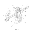
- a finger pinch preventing hand-held quick-clamping device in accordance with the present invention comprises a shifting lever 1, a fixed handle 2, a drive handle 3, and a jaw holder 4.
- the shifting lever 1 is affixed to the jaw holder 4 and inserted through the fixed handle 2.
- a first jaw 41 is fixedly arranged on one end of the jaw holder 4 remote from the shifting lever 1.
- a second jaw 21 is fixedly arranged on one end of the fixed handle 2 corresponding to the first jaw 41 at the jaw holder 4.
- the drive handle 3 is pivotally connected to the fixed handle 2, having a grip 30 located on its one end (the bottom end) remote from the fixed handle 2.
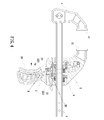
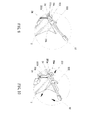
- the drive handle 3 is operable to move actuating plates 5 and stop plates 6 in the fixed handle 2. When the drive handle 3 is pressed (see FIG.
- actuating plates 5 are forced to move the shifting lever 1 in one direction relative to the fixed handle 2, thereby causing the first jaw 41 to be moved toward the second jaw 21 to clamp the workpiece, or apart from the second jaw 21 to release the workpiece.
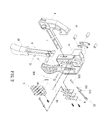
- a release lever 22 is pivotally connected to the fixed handle 2.
- the release lever 22 comprises an arched push block 222 and a triggering tip 221.
- a movable stop block 23 is set in the fixed handle 2.
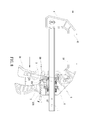
- the arched front block 222 will be forced to move the stop plates 6 out of the engagement position, and the triggering tip 221 will be synchronously forced to move the movable stop block 23 into engagement with the drive handle 3, stopping the drive handle 3 (or the grip 30 of the drive handle 3) from touching the fixed handle 2. Therefore, the invention prevents a finger pinch when the drive handle 3 jumps back after each clamping operation.
- the drive handle 3 comprises a butt 31 for stopping against the movable stop block 23 so that a gap A will be kept in between the fixed handle 2 and the drive handle 3 (or the grip 30 of the drive handle 3) when the drive handle 3 jumps back to release the stored spring power of the quick-clamping device (se FIG. 7 ), preventing accidental finger injury.
- the arched push block 222 is located on the front end of the release lever 22; the triggering tip 221 extends forwardly from the front side of the arched front block 222. Further, an end piece 223 may be capped on the triggering tip 221 (see FIG. 2 ).
- the release lever 22 is biased to force the arched front block 222 in moving the stop plates 6 out of the engagement position, the triggering tip 221 or the end piece 223 will be synchronously forced to move the movable stop block 23 into stoppage against the drive handle 3 or the butt 31 of the drive handle 3, stopping the drive handle 3 (or the grip 30 of the drive handle 3) (see FIG. 1 or FIG. 7 ), prohibiting the drive handle 3 (or the grip 30 of the drive handle 3) from impacting the fixed handle 2 and preventing accidental finger injury when the drive handle 3 jumps back to release the stored spring power of the quick-clamping device.
- the movable stop block 23 has a beveled face 231 located on its one lateral side for contacting the end piece 223 at the triggering tip 221 of the release lever 22 (it is to be understood that the end piece 223 is simply an optional member but not a requisite). Normally, the end piece 223 (or the triggering tip 221) of the release lever 22 is stopped at the bottom side of the beveled face 231 of the movable stop block 23 (see FIG. 5 ).
- the movable stop block 23 is supported on a return spring 24.
- the return spring 24 is a spring wire rod, having its one end connected to the movable stop block 23 and its other end connected to the fixed handle 2. Due to the functioning of the return spring 24, the movable stop block 23 will be automatically returned to its former position by the return spring 24 after each operation of the release lever 22.
- FIG. 8 illustrates an alternate form of the present invention.
- the triggering tip 221' is integrally formed with the front end of the release lever 22'.
- the triggering tip 221 or 221' can be made in any of a variety of shapes capable of moving the movable stop block 23.
- the drive handle 3' of this alternate form eliminates the aforesaid butt 31, and is stoppable with its inner side edge against the movable stop block 23 to leave a gap A in between the fixed handle 2 and the drive handle 3', thus preventing a finger pinch.
- FIG. 9 illustrates another alternate form of the present invention.
- two movable stop blocks 23a;23b are set in the fixed handle 2 at two opposite sides relative to the end piece 223 at the triggering tip 221 of the release lever 22.
- the triggering tip 221 or the end piece 223 will be forced to move the two movable stop blocks 23a;23b bilaterally outwards into stoppage against the drive handle 3 (see FIG. 10 ), prohibiting the drive handle 3 from impacting the fixed handle 2 and preventing accidental finger injury.
- the return spring 24 can be a torsion spring or a compression spring instead of the aforesaid spring wire rod. Accordingly, the invention is not to be limited except as by the appended claims.
Landscapes
- Engineering & Computer Science (AREA)
- Mechanical Engineering (AREA)
- Manipulator (AREA)
Priority Applications (1)
| Application Number | Priority Date | Filing Date | Title |
|---|---|---|---|
| EP11152020A EP2479005A1 (fr) | 2011-01-25 | 2011-01-25 | Dispositif de serrage rapide manuel empêchant le pincement de doigts |
Applications Claiming Priority (1)
| Application Number | Priority Date | Filing Date | Title |
|---|---|---|---|
| EP11152020A EP2479005A1 (fr) | 2011-01-25 | 2011-01-25 | Dispositif de serrage rapide manuel empêchant le pincement de doigts |
Publications (1)
| Publication Number | Publication Date |
|---|---|
| EP2479005A1 true EP2479005A1 (fr) | 2012-07-25 |
Family
ID=43896593
Family Applications (1)
| Application Number | Title | Priority Date | Filing Date |
|---|---|---|---|
| EP11152020A Withdrawn EP2479005A1 (fr) | 2011-01-25 | 2011-01-25 | Dispositif de serrage rapide manuel empêchant le pincement de doigts |
Country Status (1)
| Country | Link |
|---|---|
| EP (1) | EP2479005A1 (fr) |
Citations (4)
| Publication number | Priority date | Publication date | Assignee | Title |
|---|---|---|---|---|
| US6676120B1 (en) * | 2000-10-26 | 2004-01-13 | M. Susan Hallbeck | Bar clamp having ergonomic handle |
| WO2004004976A2 (fr) * | 2002-07-09 | 2004-01-15 | Irwin Industrial Tool Company | Serre-joint à barre avec levier de freinage activé latéralement |
| EP2036677A2 (fr) * | 2007-09-13 | 2009-03-18 | The Stanley Works | Pince à mâchoire amovible |
| US7513492B1 (en) | 2008-03-20 | 2009-04-07 | Sheng Pu Promotion Co., Ltd. | Hand held quick-clamping device |
-
2011
- 2011-01-25 EP EP11152020A patent/EP2479005A1/fr not_active Withdrawn
Patent Citations (4)
| Publication number | Priority date | Publication date | Assignee | Title |
|---|---|---|---|---|
| US6676120B1 (en) * | 2000-10-26 | 2004-01-13 | M. Susan Hallbeck | Bar clamp having ergonomic handle |
| WO2004004976A2 (fr) * | 2002-07-09 | 2004-01-15 | Irwin Industrial Tool Company | Serre-joint à barre avec levier de freinage activé latéralement |
| EP2036677A2 (fr) * | 2007-09-13 | 2009-03-18 | The Stanley Works | Pince à mâchoire amovible |
| US7513492B1 (en) | 2008-03-20 | 2009-04-07 | Sheng Pu Promotion Co., Ltd. | Hand held quick-clamping device |
Similar Documents
| Publication | Publication Date | Title |
|---|---|---|
| US7017894B1 (en) | Vise clamp | |
| KR0142018B1 (ko) | 체결용 공구 | |
| US8061573B2 (en) | Mode switch for fastener driving tool | |
| US5009134A (en) | Quick-action bar clamp | |
| US5335838A (en) | Stapling machine | |
| US7624974B2 (en) | Release mechanism of bar clamp | |
| EP3437803B1 (fr) | Mécanisme de verrouillage de tir à vide destiné à un pilote d'attache propulsée | |
| NO324987B1 (no) | Anordning for a justere drivdybden pa et festemiddel drivverktoy med utskiftbart kontaktelement og metode for a skifte kontaktelementer | |
| US20050120770A1 (en) | Electrohydraulic pressing device and method for operating the same | |
| US9751193B2 (en) | Clamping and spreading tool | |
| US20080185415A1 (en) | Trigger Switch Mechanism of Nail Gun | |
| US5018275A (en) | Cutting device | |
| US20090313836A1 (en) | Safety cutter knife | |
| US20120175397A1 (en) | Flat-clinch stapler | |
| EP1693156A3 (fr) | Outil entraîné par gaz de combustion avec installation pour protéger le commutateur | |
| EP3456477A1 (fr) | Cloueuse | |
| US20120187617A1 (en) | Finger pinch preventing hand-held quick-clamping device | |
| US20140284369A1 (en) | Staple-ejecting type stapler | |
| JP7383045B2 (ja) | ハンドヘルド・ジャッキングツールのための降下機構 | |
| EP3287238A1 (fr) | Ensemble de déclenchement pour un outil pneumatique | |
| EP2479005A1 (fr) | Dispositif de serrage rapide manuel empêchant le pincement de doigts | |
| EP3243605B1 (fr) | Dispositif de sécurité pour agrafeuses | |
| US11065751B2 (en) | Labor-saving stapler | |
| US20080061106A1 (en) | Stapler having a force balance effect | |
| US6978986B2 (en) | Clamping device |
Legal Events
| Date | Code | Title | Description |
|---|---|---|---|
| PUAI | Public reference made under article 153(3) epc to a published international application that has entered the european phase |
Free format text: ORIGINAL CODE: 0009012 |
|
| AK | Designated contracting states |
Kind code of ref document: A1 Designated state(s): AL AT BE BG CH CY CZ DE DK EE ES FI FR GB GR HR HU IE IS IT LI LT LU LV MC MK MT NL NO PL PT RO RS SE SI SK SM TR |
|
| AX | Request for extension of the european patent |
Extension state: BA ME |
|
| STAA | Information on the status of an ep patent application or granted ep patent |
Free format text: STATUS: THE APPLICATION IS DEEMED TO BE WITHDRAWN |
|
| 18D | Application deemed to be withdrawn |
Effective date: 20130126 |