EP2478855B1 - Treatment device - Google Patents
Treatment device Download PDFInfo
- Publication number
- EP2478855B1 EP2478855B1 EP12151483.0A EP12151483A EP2478855B1 EP 2478855 B1 EP2478855 B1 EP 2478855B1 EP 12151483 A EP12151483 A EP 12151483A EP 2478855 B1 EP2478855 B1 EP 2478855B1
- Authority
- EP
- European Patent Office
- Prior art keywords
- needle
- indicator
- treatment device
- controller
- movement distance
- Prior art date
- Legal status (The legal status is an assumption and is not a legal conclusion. Google has not performed a legal analysis and makes no representation as to the accuracy of the status listed.)
- Not-in-force
Links
Images


Classifications
-
- A—HUMAN NECESSITIES
- A61—MEDICAL OR VETERINARY SCIENCE; HYGIENE
- A61B—DIAGNOSIS; SURGERY; IDENTIFICATION
- A61B8/00—Diagnosis using ultrasonic, sonic or infrasonic waves
-
- A—HUMAN NECESSITIES
- A61—MEDICAL OR VETERINARY SCIENCE; HYGIENE
- A61B—DIAGNOSIS; SURGERY; IDENTIFICATION
- A61B17/00—Surgical instruments, devices or methods, e.g. tourniquets
- A61B17/34—Trocars; Puncturing needles
- A61B17/3403—Needle locating or guiding means
-
- A—HUMAN NECESSITIES
- A61—MEDICAL OR VETERINARY SCIENCE; HYGIENE
- A61B—DIAGNOSIS; SURGERY; IDENTIFICATION
- A61B10/00—Other methods or instruments for diagnosis, e.g. instruments for taking a cell sample, for biopsy, for vaccination diagnosis; Sex determination; Ovulation-period determination; Throat striking implements
- A61B10/02—Instruments for taking cell samples or for biopsy
- A61B10/0233—Pointed or sharp biopsy instruments
-
- G—PHYSICS
- G01—MEASURING; TESTING
- G01N—INVESTIGATING OR ANALYSING MATERIALS BY DETERMINING THEIR CHEMICAL OR PHYSICAL PROPERTIES
- G01N29/00—Investigating or analysing materials by the use of ultrasonic, sonic or infrasonic waves; Visualisation of the interior of objects by transmitting ultrasonic or sonic waves through the object
- G01N29/22—Details, e.g. general constructional or apparatus details
- G01N29/24—Probes
-
- A—HUMAN NECESSITIES
- A61—MEDICAL OR VETERINARY SCIENCE; HYGIENE
- A61B—DIAGNOSIS; SURGERY; IDENTIFICATION
- A61B17/00—Surgical instruments, devices or methods, e.g. tourniquets
- A61B17/34—Trocars; Puncturing needles
- A61B17/3403—Needle locating or guiding means
- A61B2017/3405—Needle locating or guiding means using mechanical guide means
-
- A—HUMAN NECESSITIES
- A61—MEDICAL OR VETERINARY SCIENCE; HYGIENE
- A61B—DIAGNOSIS; SURGERY; IDENTIFICATION
- A61B17/00—Surgical instruments, devices or methods, e.g. tourniquets
- A61B17/34—Trocars; Puncturing needles
- A61B17/3403—Needle locating or guiding means
- A61B2017/3413—Needle locating or guiding means guided by ultrasound
-
- A—HUMAN NECESSITIES
- A61—MEDICAL OR VETERINARY SCIENCE; HYGIENE
- A61B—DIAGNOSIS; SURGERY; IDENTIFICATION
- A61B34/00—Computer-aided surgery; Manipulators or robots specially adapted for use in surgery
- A61B34/20—Surgical navigation systems; Devices for tracking or guiding surgical instruments, e.g. for frameless stereotaxis
- A61B2034/2046—Tracking techniques
- A61B2034/2059—Mechanical position encoders
-
- A—HUMAN NECESSITIES
- A61—MEDICAL OR VETERINARY SCIENCE; HYGIENE
- A61B—DIAGNOSIS; SURGERY; IDENTIFICATION
- A61B90/00—Instruments, implements or accessories specially adapted for surgery or diagnosis and not covered by any of the groups A61B1/00 - A61B50/00, e.g. for luxation treatment or for protecting wound edges
- A61B90/06—Measuring instruments not otherwise provided for
- A61B2090/062—Measuring instruments not otherwise provided for penetration depth
-
- A—HUMAN NECESSITIES
- A61—MEDICAL OR VETERINARY SCIENCE; HYGIENE
- A61B—DIAGNOSIS; SURGERY; IDENTIFICATION
- A61B90/00—Instruments, implements or accessories specially adapted for surgery or diagnosis and not covered by any of the groups A61B1/00 - A61B50/00, e.g. for luxation treatment or for protecting wound edges
- A61B90/08—Accessories or related features not otherwise provided for
- A61B2090/0807—Indication means
- A61B2090/0811—Indication means for the position of a particular part of an instrument with respect to the rest of the instrument, e.g. position of the anvil of a stapling instrument
Definitions
- the present disclosure relates to the field of treatment devices.
- the disclosure is particularly applicable to treatment devices for measuring movement of a needle to control insertion length of the needle, thereby improving stability of a biopsy or treatment.
- a needle biopsy is used to diagnose a target, such as in biological tissue or a human body, suspected to be a tumor and choosing a treatment method based on such diagnosis.
- One type of needle biopsy is an image guided needle biopsy using ultrasonic waves, X-ray, magnetic resonance imaging (MRI) or computer tomography (CT), in which an invisible needle is inserted into a human body.
- MRI magnetic resonance imaging
- CT computer tomography
- a needle guide for guiding the needle is provided in a probe.
- One conventional probe is an ultrasonic diagnostic device. During biopsy, the needle moves along the needle guide to sample a target.
- the needle moving to the front of the probe, is not easily distinguished from tissue around the needle. If a needle insertion route is not properly displayed in an image projected on an imaging device, it may be difficult for a user to confirm the movement distance of the needle. As a result, the possibility of error resulting in medical malpractice may be increased.
- a treatment device according to the preamble of claim 1 is known from US patent no. 6 146 329 .
- a treatment device according to claim 1 is provided.
- one embodiment of the present disclosure includes a treatment device 1.
- the treatment device 1 includes a probe 10 for acquiring an image of a target (not shown) using ultrasonic waves.
- a needle guide 20 is provided in the probe 10.
- a needle 30 is movable along the needle guide 20.
- a measurement unit 40 senses a movement distance of the needle 30 in a noncontact fashion, and a controller 40 calculates the movement distance of the needle 30 based on a value measured by the measurement unit 40.
- ultrasonic diagnostic devices may be used as the probe 10 as long as the ultrasonic diagnostic devices acquire an image of a target using ultrasonic waves.
- the probe 10 transmits an ultrasonic signal, such as the signal 55 as shown in FIG. 7 , to a target (not shown) and receives an ultrasonic signal reflected from the target to acquire an ultrasonic image of the target.
- an ultrasonic signal such as the signal 55 as shown in FIG. 7
- the probe 10 can be connected to a main unit 60 so that the ultrasonic signal received by the probe 10 is transmitted to the main unit 60.
- the main unit 60 includes a main body 62, in which various kinds of equipment are installed.
- a manipulation panel 64 is connected to the main body 62 to allow a user to input a manipulation signal.
- a display unit 66 displays the signal received by the probe 10.
- the needle guide 20 is provided along the probe 10 in the embodiment shown in FIG. 3 .
- the needle guide 20 may be formed in any shape suitable to allow for the needle guide 20 to guide movement of the needle 30.
- the needle guide 20 includes a guide pipe 21 provided along the probe 10 to define a passage therein, an inlet 22 provided at one side (right side in FIG. 2 ) of the guide pipe 21, and an outlet 23 provided at the other side (left side in FIG. 2 ) of the guide pipe 21.
- the inlet 22 has a diameter greater than that of the guide pipe 21 so that the needle 30 easily enters the guide pipe 21. A portion of the inlet 22 connected to the guide pipe 21 can be inclined to guide movement of the needle 30.
- a hook 24 protruding from the outlet 23 catches the probe 10 to fix the outlet 23 to the probe 10.
- connection member 26 connected to the inlet 22 or the guide pipe 21 is formed in the shape of a band.
- the connection member 26 is provided to wrap the probe 10 and the guide pipe 21 of the needle guide 20. Opposite ends of the connection member 26 are fixed by a fastening bolt 27.
- the needle 30 moves along the guide pipe 21 through the inlet 22 and is withdrawn from the needle guide 20 through the outlet 23 to insert the needle 30 into a target.
- the needle 30 may be formed in any shape suitable to allow for the needle 30 to move along the needle guide 20 to sample or treat a target.
- the needle 30 may include an insertion part, which is inserted into a target, e.g. a human body, to be measured, and an installation part, at which the measurement unit 40 is installed, to avoid infection during measurement.
- a target e.g. a human body
- an installation part at which the measurement unit 40 is installed, to avoid infection during measurement.
- the insertion part and the installation part of the needle 30 are separated from each other so that the installation part is disinfected or replaced, thereby preventing infection during measurement.
- any noncontact sensor may be used as the measurement unit 40 as long as the sensor is suitable for measuring a movement distance of the needle in a noncontact fashion.
- germs are prevented from moving along the needle 30 to provide more sanitary test environments since external contamination sources and the front end (left side in FIG. 6 ) of the needle 30 are relatively distant from the inlet 22.
- the measurement unit 40 may be provided in the middle 25 of the needle guide 20 between the inlet 22 and the outlet 23 to improve space utilization.
- the measurement unit 40 may weigh 1 kg or less. Since the measurement unit 40 is relatively light, a user may easily manipulate the treatment device 1 including the measurement unit 40.
- the measurement unit 40 includes a first indicator 44 formed at the outside of the needle 30 for indicating length information and a camera 42 for capturing and transmitting the first indicator 44 to the controller 50 as an image signal.
- the first indicator 44 may have a color or pattern varying according to the length information of the needle 30 so that a user recognizes an outward movement distance of the needle 30 through the outlet 23 of the needle guide 20.
- the first indicator 44 may indicate a measurement start part and a measurement end part. Also, the first indicator 44 may include distance information of a region at which the needle 30 is located.
- patterns showing front and rear ends of the first indicator 44 are different from each other. Consequently, the measurement start part and the measurement end part are easily confirmed based on such patterns.
- the first indicator 44 includes various colors, which change based on a movement distance of the needle 30.
- the colors are arranged at predetermined intervals, and the camera 42 captures and transmits the first indicator 44 provided at the outside of the needle 30 to the controller 50, thereby calculating the movement distance of the needle 30.
- the first indicator 44 may be variously modified as long as the first indicator 44 indicates information to calculate the movement distance of the needle 30 based on changed colors or patterns.
- the first indicator 44 may be attached to the outside of the needle 30 as a sticker. Alternatively, the first indicator 44 may be attached to the outside of the needle 30 using various methods, such as painting or processing.
- the first indicator 44 includes indicator bands 46, which are provided at the outside of the needle 30 at a predetermined interval.
- a start part of the first indicator 44 is a position measured by the camera 42 immediately before the needle 30 is withdrawn from the outlet 23, and an end part of the first indicator 44 is a position measured by the camera 42 after the needle 30 is inserted into a target.
- Such positions of the first indicator 44 correspond to a movement distance of the needle withdrawn from the outlet 23.
- Any image capturing device may be used as the camera 42 as long as the capturing devices are suitable for capturing an image of the first indicator 44 and transmit an image signal to the controller 50.
- the camera 42 may be provided at various positions.
- the camera 42 may be provided inside the inlet 22 or in the middle 25 located between the inlet 22 and the outlet 23.
- An image captured by the camera 42 may be transmitted to the controller 50 in a wired or wireless fashion. Also, power may be supplied to the camera 42 in a wired or wireless fashion.
- the camera 42 may capture a set number of frames per second and transmit the captured frames to the controller 50. Alternatively, the camera 42 may analyze a movement distance of the needle 30 based on the number of frames and transmit only a measured value to the controller 50.
- a transparent protective film (not shown) may be provided between the camera 42 and the needle 30 to protect the camera 42.
- the controller 50 calculates a movement distance of the needle 30 based on a value measured by the measurement unit 40, and an ultrasonic image signal measured by the probe 10 is also transmitted to the controller 50.
- the manipulation panel 64 which allows a user to input a manipulation signal, is connected to the controller 50 to transmit a signal to the controller 50.
- the controller 50 synthesizes and outputs signals from the probe 10, the measurement unit 40 and the manipulation panel 64 to the display unit 66.
- the controller 50 may be disposed at one or more selected from among the probe 10, the needle guide 20 and the main unit 60.
- the needle 30 is moved toward the inlet 22 of the needle guide 20. Subsequently, as shown in FIG. 5 , the needle 30 is inserted through the inlet 22 and is moved along the guide pipe 21.
- the indicator bands 46 of the first indicator 44 are captured by the camera 42.
- the first indicator 44 moves with the needle 30.
- the camera 42 captures the first indicator 44 and transmits images on a per frame basis to the controller 50.
- the controller 50 compares an image pattern signal transmitted from the camera 42 with a stored image pattern signal to measure a movement distance of the needle 30.
- the number of the indicator bands 46 captured by the camera 42 may be multiplied by an interval between the indicator bands 46 to measure the movement distance of the needle 30.
- the controller 50 calculates the movement distance of the needle 30 based on a value measured by the camera 42 and provides the result to a user.
- the controller 50 may provide the movement distance of the needle 30 to the user through the display unit 66.
- a speaker may be used to provide the movement distance of the needle 30 to the user via audio signals.
- the user confirms the movement distance of the needle 30 through the display unit 66, thereby more safely sampling or treating a target.
- Various calculation expressions and methods may be used to calculate the length of the needle 30 inserted into a human body using the treatment device 1 according to certain embodiments.
- the distance from the front end (left side in FIG. 7 ) of the outlet 23 to the camera 42 is expressed by a symbol 'a'.
- a beam irradiation surface 55, to which ultrasonic waves are irradiated to acquire an image, is provided at the front (left side in FIG. 7 ) of the probe 10.
- the distance from the interface between the beam irradiation surface 55 and the needle 30 to the front end of the outlet 23 is expressed by a symbol 'b'.
- the distance from a zero position (left side in FIG. 7 ), which is a reference position of the first indicator 44, to the camera 42 of the measurement unit 40 to sense a position is expressed by a symbol 'c'.
- a value of 'c' may be acquired through the measurement unit 40.
- the distance from the zero position, which is the reference position of the first indicator 44, to the front end (left side in FIG. 7 ) of the needle 30 is expressed by a symbol 'e'.
- Values of 'a', 'b' and 'e' may be kinematically calculated or acquired through real measurement. These values are stored in the controller 50. The value of 'c' may be acquired through the operation of the measurement unit 40 according to movement of the needle 30. This value is transmitted to the controller 50.
- the front end (left side in FIG. 7 ) of the probe 10 is a part contacting a target to be tested, i.e. a human body.
- the distance from the front end of the probe 10 to the front end of the needle 30 is a length of the needle 30 inserted into the human body, which is expressed by a symbol 'g'.
- the length from the front end of the probe 10 to the front end of the outlet 23 may be expressed by a symbol 'f'.
- Values of 'b' and 'f' are stored in the controller.
- a measurement unit 70 of the treatment device 2 includes a first indicator 44 for indicating length information at the outside of a needle 30, a camera 42 for capturing and transmitting the first indicator 44 to a controller 50 as an image signal, and a first optical sensor 72 for measuring movement of the first indicator 44 by transmitting and receiving light.
- the first optical sensor 72 includes a light emitting part for irradiating light to the needle 30 and a light receiving part for sensing light reflected from the needle 30.
- Any suitable light emitting devices including a light emitting diode (LED), may be used as the light emitting part of the first optical sensor 72.
- An electric device to receive and convert light reflected from the needle 30 or the first indicator 44 into an electric signal may be used as the light receiving part of the first optical sensor 72.
- An optical sensor used in an optical mouse may be used as the first optical sensor 72.
- the optical sensor may cooperate with the camera 42 to measure a movement distance of the needle 30.
- a value measured by the first optical sensor 72 may be transmitted to the controller 50.
- the value measured by the first optical sensor 72 may be analyzed by a digital signal processing chip (DSPC) to calculate a movement distance of the needle 30. The value themn may be transmitted to the controller 50.
- DSPC digital signal processing chip
- the treatment device 2 measures a movement distance of the needle 30 using the camera 42 and the first optical sensor 72, thereby more accurately measuring the movement distance of the needle 30.
- the first indicator 44 is captured by the camera 42.
- the first indicator 44 moves with the needle 30.
- the camera 42 captures the first indicator 44 and transmits images on a per frame basis to the controller 50.
- the first optical sensor 72 measures a movement distance of the needle 30 and transmits a measured value to the controller 50.
- the controller 50 calculates the movement distance of the needle 30 using the number of indicator bands 46 captured by the camera 42 and an interval between the indicator bands 46.
- the movement distance of the needle 30 is calculated based on a value measured by the first optical sensor 72 and is set to an average of the measured values acquired by the camera 42 and the first optical sensor 72.
- the controller 50 may provide the movement distance of the needle 30 to a user through a display unit 66.
- an additional speaker may be used to provide the movement distance of the needle 30 to the user.
- the user easily confirms the movement distance of the needle 30 through the display unit 66, thereby safely sampling or treating a target.
- a measurement unit 80 of the treatment device 3 includes an irradiation unit 82 for irradiating light of a predetermined wavelength at a predetermined time interval, a second indicator 84 having a pattern formed of a paint, and reflecting the light of the predetermined wavelength among the light irradiated from the irradiation unit 82, an optical sensor 86 for sensing the light of the wavelength reflected from the second indicator, and a second optical sensor 88 for measuring movement of the second indicator 84.
- the measurement unit 80 may be provided in an inlet 22, through which a needle 30 is inserted into a needle guide 20, in a probe 10 adjacent to the inlet 22, or the middle 25 of the needle guide 20.
- any irradiation device may be used as the irradiation unit 82 as long as the irradiation device is suitable for irradiating light of a specific wavelength to the needle 30.
- the irradiation unit 82 may continuously irradiate light of a predetermined wavelength or irradiate light of a predetermined wavelength at a predetermined time interval.
- the second indicator 84 includes a paint reflecting light of a specific wavelength. The second indicator 84 is provided at the rear side (right side in FIG. 10 ) of the needle 30 to detour around an insertion part of the needle 30, which is inserted into a human body.
- the second indicator 84 may be provided at the outside of the needle 30 using various methods, such as printing, application and attachment.
- the paint is provided at the second indicator 84 at a predetermined interval to repeatedly reflect and block light irradiated from the irradiation unit 82 toward the optical sensor 86.
- the light reflected from the second indicator 84 is received by the optical sensor 86 and converted into an electric signal, which is transmitted to the controller 50.
- the movement distance of the needle 30 may be measured using the irradiation unit 82, the second indicator 84 and the optical sensor 86.
- the second optical sensor 88 is provided to measure the movement distance of the needle 30.
- the second optical sensor 88 according to one embodiment has the same construction and operation as the first optical sensor 72 according to the previous embodiment shown in FIGS. 9 and 10 , and therefore, a detailed description thereof will be omitted.
- the irradiation unit 82 irradiates light of a specific wavelength to the second indicator 84.
- the light of the specific wavelength reflected from the second indicator 84 is received by the optical sensor 86 and converted into an electric signal, which is transmitted to the controller 50.
- the second indicator 84 moves with the needle 30. According to the movement of the second indicator 84, the light from the irradiation unit 82 is repeatedly reflected and non-reflected to the optical sensor 86. The optical sensor 86 generates an electric signal based on when the light is received and when the light is not received.
- the controller 50 analyzes the signal of the second indicator 84 measured by the optical sensor 86 to calculate the movement distance of the needle 30.
- the movement distance of the needle 30 is calculated based on a value measured by the second optical sensor 88 and is set to an average of the measured values acquired by the optical sensor 86 and the second optical sensor 88.
- a treatment device 4 according to another embodiment of the present disclosure, however, not forming part of the present invention, will be described with reference to the accompanying drawings.
- components of this embodiment identical in construction and operation to those of the previous embodiment shown in FIGS. 1 to 8 are denoted by the same reference numerals, and a detailed description thereof will be omitted.
- a measurement unit 90 of the treatment device 4 includes a magnetic field generation unit 92 for generating a magnetic field at a region through which a needle 30 extends and a coil sensor 94 interlocked with the needle 30 for sensing change of the magnetic field caused while passing through the magnetic field generation unit 92.
- the magnetic field generation unit 92 is provided in a needle guide 20 or a probe 10 for generating a magnetic field in an inlet 96 of the needle guide 20.
- the magnetic field generation unit 92 may be formed in various shapes, such as a cylindrical shape.
- the magnetic field generation unit 92 generates different magnetic fields depending upon positions at which the coil sensor 94, which moves with the needle 30, is located.
- the coil sensor 94 which moves with the needle 30, is connected to the controller 50 to measure change of the magnetic field caused while passing through the magnetic field generated by the magnetic field generation unit 92 and to transmit the measured change of the magnetic field to the controller 50.
- any suitable electromagnetic device may be used as the magnetic field generation unit 92 and the coil sensor 94 as long as power is supplied to the electromagnetic device in a wired or wireless fashion so that the electromagnetic device generates a magnetic field.
- the coil sensor 94 is introduced into the magnetic field generation unit 92 to sense change of a magnetic field.
- the coil sensor 94 senses the change of the magnetic field and transmits a measured value to the controller 50. Consequently, the controller 50 recognizes the positions of the coil sensor 94 and the needle 30 at which the coil sensor 94 is provided.
- the coil sensor 94 moves with the needle 30.
- the coil sensor 94 measures magnetic fields changed depending upon the position thereof while moving along the inside of the magnetic field generation unit 92.
- the measured value is converted into an electric signal, which is transmitted to the controller 50.
- the controller 50 analyzes the magnetic field change signal measured by the coil sensor 94 to calculate the movement distance of the needle 30 and to provide the result to a user through a display unit 66.
- a measurement unit 100 of the treatment device 5 measures a movement distance of a needle 30 using electromagnetic resonance (EMR).
- EMR electromagnetic resonance
- the measurement unit 100 includes a resonance circuit 102 interlocked with the needle 30 and a resonance sensor 104, provided at a region through which the needle 30 extends, to transmit and receive electric waves to and from the resonance circuit 102 to measure the movement distance of the needle 30.
- the resonance sensor 104 is provided in a needle guide 20 or a probe 10. Any suitable electronic device may be used as the resonance sensor 104 as long as the electronic device transmits and receive an electromagnetic signal to and from the resonance circuit 102.
- the resonance sensor 104 may be formed in any suitable shapes.
- a suitable shape is a cylindrical shape.
- Power is supplied to the resonance sensor 104, which is fixedly provided. Power is not supplied to the resonance circuit 102, which moves with the needle 30.
- the resonance sensor 104 includes a loop coil and a transmitting and receiving swap circuit.
- the resonance circuit 102 includes a coil and a condenser.
- the resonance sensor 104 receives electric waves generated from the resonance circuit 102, which moves with the needle 30, to measure the movement distance of the needle 30. A value measured by the resonance sensor 104 is converted into an electric signal, which is transmitted to the controller 50.
- the resonance circuit 102 is introduced into the resonance sensor 104.
- the resonance sensor 104 is operated in a transmitting mode and in a receiving mode.
- the transmitting mode electric waves generated by the loop coil of the resonance sensor 104 are received by the coil of the resonance circuit 102, and the condenser is charged with induced voltage generated by the electric waves.
- the receiving mode no electric waves are transmitted from the loop coil, and the resonance circuit 102 performs free oscillation.
- predetermined electric waves are generated by the coil. Induced voltage is generated by the loop coil of the resonance sensor 104, which receives the electric waves. A value measured by the resonance sensor 104 is converted into an electric signal, which is transmitted to the controller 50.
- the resonance sensor 104 receives different electric waves caused by the resonance circuit 102, which moves in the resonance sensor 104 along with the needle 30. Such a signal is transmitted to the controller 50, which calculates the movement distance of the resonance circuit 102 and the needle 30, in which the resonance circuit 102 is provided. The result is provided to a user through a display unit 66.
- the treatment device 1, 2, 3, 4 or 5 senses the movement distance of the needle 30 in a noncontact fashion. Consequently, contamination of the needle 30 is prevented, and the movement distance of the needle 30 is accurately measured, thereby improving stability of biopsy.
- the measurement unit 40, 70, 80, 90 or 100 is selectively provided in the needle 30, the needle guide 20 and the probe 10. Consequently, no additional space is needed, thereby improving space utilization.
- a treatment device may further include a needle sensing unit 120 to determine whether the needle 30 has reached a reference position 110.
- the measurement unit 40, 70, 80, 90 or 100 is driven based on the determination of the needle sensing unit 120 to measure the movement distance of the needle 30.
- the reference position means a position at which the measurement unit begins measurement when the needle reaches the position.
- this embodiment includes the measurement unit 40 of the previous embodiment shown in FIGS. 1 to 8 .
- the reference position 110 is provided below the camera 42.
- the first indicator 44 which moves with the needle 30, reaches the reference position 110, the camera 42 is driven.
- a contact type sensor or a noncontact type sensor may be used as the needle sensing unit 120, which drives the camera 42.
- the needle sensing unit 120 includes a recognition member 122 provided at the outside of the needle 30 and a recognition sensor 124 to recognize the recognition member 122 to drive the needle sensing unit 120.
- the recognition member 122 may be formed in any suitable shape as long as the recognition member 122 is recognized by the needle sensing unit 120.
- the recognition member 122 is disposed at the outside of the needle 30, and is band-shaped. Consequently, the recognition member 122 is easily recognized by the needle sensing unit 120 irrespective of directivity of the needle 30.
- the recognition sensor 124 is operated in a contact or noncontact fashion to recognize the recognition member 122.
- the recognition sensor 124 recognizes the recognition member 122 through transmission and reception of light. Consequently, operational reliability of the recognition sensor 124 is secured although the recognition sensor 124 is repeatedly used.
- the distance between the recognition sensor 124 and the camera 42 is equal to that between the recognition member 122 and the first indicator 44.
- the camera 42 measures the first indicator 44 having reached the reference position 110 in an initialized state.
- the controller 50 calculates a movement distance of the needle 30 based on a value measured by the measurement unit 40, and an ultrasonic image signal measured by the probe 10 is also transmitted to the controller 50.
- the manipulation panel 64 which allows a user to input a manipulation signal, is connected to the controller 50 to transmit a signal to the controller 50.
- the controller 50 synthesizes and outputs signals from the probe 10, the measurement unit 40 and the manipulation panel 64 to the display unit 66.
- the controller 50 may be disposed at one or more selected from among the probe 10, the needle guide 20 and the main unit 60.
- the needle 30 is moved toward the inlet 22 of the needle guide 20. Subsequently, as shown in FIG. 21 , the needle 30 is inserted through the inlet 22 and is moved along the guide pipe 21.
- the needle sensing unit 120 transmits a measured signal to the controller 50, which transmits a drive signal to the camera 42 of the measurement unit 40.
- the recognition sensor 124 may directly transmit a drive signal to the camera 42 to drive the camera, and the indicator bands 46 of the first indicator 44 are captured by the camera 42.
- the first indicator 44 moves with the needle 30.
- the camera 42 captures the first indicator 44 and transmits images on a per frame basis to the controller 50.
- the controller 50 compares an image pattern signal transmitted from the camera 42 with a stored image pattern signal to measure a movement distance of the needle 30.
- the number of the indicator bands 46 captured by the camera 42 may be multiplied by an interval between the indicator bands 46 for measuring the movement distance of the needle 30.
- the controller 50 calculates the movement distance of the needle 30 based on a value measured by the camera 42 and provides the result to a user.
- the controller 50 may provide the movement distance of the needle 30 to the user through the display unit 66.
- an additional speaker may be used to provide the movement distance of the needle 30 to the user via audio signals.
- the user easily confirms the movement distance of the needle 30 through the display unit 66, thereby more safely sampling or treating a target.
- Any suitable calculation expressions and methods may be used to calculate the length of the needle 30 inserted into a human body using the treatment device according to this embodiment. The method previously explained with reference to FIG. 7 may be used.
- the measurement unit 40 measures length information of the needle 30 based on the operation of the needle sensing unit 120 to determine whether the needle 30 has reached the reference position 110. Consequently, contamination of the needle 30 is prevented, and the movement distance of the needle 30 is accurately measured, thereby improving stability of biopsy.
- this embodiment adopts the measurement unit 40 of the previous embodiment shown in FIGS. 1 to 8
- the operation of the measurement units 40, 70, 80, 90 and 100 may be controlled by the needle sensing unit.
- the movement distance of the needle is sensed in a noncontact fashion, and the measurement unit measures length information of the needle based on the operation of the needle sensing unit to determine whether the needle has reached the reference position. Consequently, contamination of the needle is prevented, and the movement distance of the needle is accurately measured, thereby improving stability of biopsy.
- the measurement unit is selectively provided in the needle, the needle guide and the probe. Consequently, no additional space is needed, thereby improving space utilization.
Description
- The present disclosure relates to the field of treatment devices. The disclosure is particularly applicable to treatment devices for measuring movement of a needle to control insertion length of the needle, thereby improving stability of a biopsy or treatment.
- A needle biopsy is used to diagnose a target, such as in biological tissue or a human body, suspected to be a tumor and choosing a treatment method based on such diagnosis.
- One type of needle biopsy is an image guided needle biopsy using ultrasonic waves, X-ray, magnetic resonance imaging (MRI) or computer tomography (CT), in which an invisible needle is inserted into a human body.
- A needle guide for guiding the needle is provided in a probe. One conventional probe is an ultrasonic diagnostic device. During biopsy, the needle moves along the needle guide to sample a target.
- The above-mentioned technology is merely a related art provided to assist in understanding of the prevent disclosure.
- In an ultrasonic image, the needle, moving to the front of the probe, is not easily distinguished from tissue around the needle. If a needle insertion route is not properly displayed in an image projected on an imaging device, it may be difficult for a user to confirm the movement distance of the needle. As a result, the possibility of error resulting in medical malpractice may be increased.
- A treatment device according to the preamble of
claim 1 is known fromUS patent no. 6 146 329 . - It is an aspect of the present disclosure to provide a treatment device that accurately measures a movement distance of a needle, thereby improving stability of biopsy. Additional aspects of the disclosure will be set forth in the description which follows, will be obvious from the description, or may be learned by practice of, or techniques described in the disclosure.
- In accordance with one aspect of the present disclosure, a treatment device according to
claim 1 is provided. - The aspects of the disclosure will become apparent and more readily appreciated from the following description of the embodiments, taken in conjunction with reference to the accompanying drawings of which:
-
FIG. 1 is a perspective view showing a main unit connected to a treatment device according to an embodiment of the present disclosure; -
FIG. 2 is an exploded perspective view of the treatment device according to the embodiment of the present disclosure; -
FIG. 3 is an assembled perspective view of the treatment device according to the embodiment of the present disclosure; -
FIG. 4 is a perspective view, partially cutaway, showing the construction of a measurement unit according to an embodiment of the present disclosure; -
FIG. 5 is a sectional view showing a state of a needle of the treatment device according to the embodiment of the present disclosure before being withdrawn from a needle guide; -
FIG. 6 is a sectional view showing a state of a first indicator according to an embodiment of the present disclosure measured by a camera; -
FIG. 7 is a sectional view showing symbols to calculate a length of the needle of the treatment device according to the embodiment of the present disclosure inserted into a target; -
FIG. 8 is a block diagram of the treatment device according to the embodiment of the present disclosure; -
FIG. 9 is a sectional view showing a state of a needle of a treatment device according to another embodiment of the present disclosure before being withdrawn from a needle guide; -
FIG. 10 is a sectional view showing a state of a first indicator measured by a camera and a first optical sensor according to another embodiment of the present disclosure; -
FIG. 11 is a sectional view showing a state of a needle of a treatment device according to another embodiment of the present disclosure before being withdrawn from a needle guide; -
FIG. 12 is a sectional view showing a state of a second indicator measured by an optical sensor and a second optical sensor according to another embodiment of the present disclosure; -
FIG. 13 is a sectional view showing a state of a needle of a treatment device according to another embodiment of the present disclosure, however, not forming part of the present invention, before being withdrawn from a needle guide; -
FIG. 14 is a sectional view showing a state of a coil sensor according to another embodiment, however, not forming part of the present invention, passing through a magnetic field generation unit together with a needle; -
FIG. 15 is a sectional view showing a state of a needle of a treatment device according to another embodiment of the present disclosure, however, not forming part of the present invention, before being withdrawn from a needle guide; -
FIG. 16 is a sectional view showing a state of a coil sensor according to another embodiment, however, not forming part of the present invention, passing through a magnetic field generation unit together with a needle; -
FIG. 17 is an exploded perspective view showing a treatment device according to another embodiment of the present disclosure; -
FIG. 18 is an assembled perspective view of the treatment device according to the embodiment of the present disclosure; -
FIG. 19 is a perspective view, partially cutaway, showing the constructions of an operation sensor and a measurement unit according to an embodiment of the present disclosure; -
FIG. 20 is a sectional view showing a state of a needle of the treatment device according to the embodiment of the present disclosure before entering an inlet; -
FIG. 21 is a sectional view showing a state of the needle of the treatment device according to the embodiment of the present disclosure before being withdrawn from a needle guide; and -
FIG. 22 is a sectional view showing a state in which a needle according to an embodiment of the present disclosure is withdrawn from a needle guide. - Reference will now be made in detail to embodiments of the present disclosure, examples of which are illustrated in the accompanying drawings, wherein like reference numerals refer to like elements throughout. For convenience of description, a medical treatment device will be described as an example. In the drawings, the thickness of each line or size of each component may be exaggerated for convenience of description and clarity. Also, terms, which will be described below, may be defined considering functions of the present disclosure, and may vary according to usual practice or intention of users or operators. Consequently, such terms may be defined based on the specification.
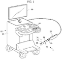
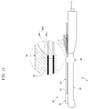
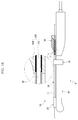
- As shown in
FIG. 2 , one embodiment of the present disclosure includes atreatment device 1. Thetreatment device 1 includes aprobe 10 for acquiring an image of a target (not shown) using ultrasonic waves. Aneedle guide 20 is provided in theprobe 10. Aneedle 30 is movable along theneedle guide 20. Ameasurement unit 40 senses a movement distance of theneedle 30 in a noncontact fashion, and acontroller 40 calculates the movement distance of theneedle 30 based on a value measured by themeasurement unit 40. - Various ultrasonic diagnostic devices may be used as the
probe 10 as long as the ultrasonic diagnostic devices acquire an image of a target using ultrasonic waves. - In certain embodiments, the
probe 10 transmits an ultrasonic signal, such as thesignal 55 as shown inFIG. 7 , to a target (not shown) and receives an ultrasonic signal reflected from the target to acquire an ultrasonic image of the target. - As illustrated in
FIG. 1 , theprobe 10 can be connected to amain unit 60 so that the ultrasonic signal received by theprobe 10 is transmitted to themain unit 60. - In this embodiment, the
main unit 60 includes amain body 62, in which various kinds of equipment are installed. Amanipulation panel 64 is connected to themain body 62 to allow a user to input a manipulation signal. Adisplay unit 66 displays the signal received by theprobe 10. - The
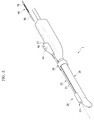
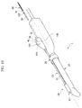
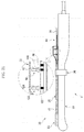
needle guide 20 is provided along theprobe 10 in the embodiment shown inFIG. 3 . Theneedle guide 20 may be formed in any shape suitable to allow for theneedle guide 20 to guide movement of theneedle 30. - In one embodiment, the
needle guide 20 includes aguide pipe 21 provided along theprobe 10 to define a passage therein, aninlet 22 provided at one side (right side inFIG. 2 ) of theguide pipe 21, and anoutlet 23 provided at the other side (left side inFIG. 2 ) of theguide pipe 21. - The
inlet 22 has a diameter greater than that of theguide pipe 21 so that theneedle 30 easily enters theguide pipe 21. A portion of theinlet 22 connected to theguide pipe 21 can be inclined to guide movement of theneedle 30. - As shown in the embodiment of
FIG. 2 , ahook 24 protruding from theoutlet 23 catches theprobe 10 to fix theoutlet 23 to theprobe 10. - A
connection member 26 connected to theinlet 22 or theguide pipe 21 is formed in the shape of a band. In this embodiment, theconnection member 26 is provided to wrap theprobe 10 and theguide pipe 21 of theneedle guide 20. Opposite ends of theconnection member 26 are fixed by afastening bolt 27. - To operate the device according to one embodiment, the
needle 30 moves along theguide pipe 21 through theinlet 22 and is withdrawn from theneedle guide 20 through theoutlet 23 to insert theneedle 30 into a target. - The
needle 30 may be formed in any shape suitable to allow for theneedle 30 to move along theneedle guide 20 to sample or treat a target. - The
needle 30 may include an insertion part, which is inserted into a target, e.g. a human body, to be measured, and an installation part, at which themeasurement unit 40 is installed, to avoid infection during measurement. - That is, the insertion part and the installation part of the
needle 30 are separated from each other so that the installation part is disinfected or replaced, thereby preventing infection during measurement. - Any noncontact sensor may be used as the
measurement unit 40 as long as the sensor is suitable for measuring a movement distance of the needle in a noncontact fashion. - In an embodiment in which the
measurement unit 40 is provided in theinlet 22, germs are prevented from moving along theneedle 30 to provide more sanitary test environments since external contamination sources and the front end (left side inFIG. 6 ) of theneedle 30 are relatively distant from theinlet 22. - In an embodiment in which the
inlet 22 has too small a space to receive themeasurement unit 40, themeasurement unit 40 may be provided in the middle 25 of theneedle guide 20 between theinlet 22 and theoutlet 23 to improve space utilization. - In certain embodiments, the
measurement unit 40 may weigh 1 kg or less. Since themeasurement unit 40 is relatively light, a user may easily manipulate thetreatment device 1 including themeasurement unit 40. - In embodiments shown in
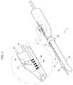
FIGS. 4-7 , themeasurement unit 40 includes afirst indicator 44 formed at the outside of theneedle 30 for indicating length information and acamera 42 for capturing and transmitting thefirst indicator 44 to thecontroller 50 as an image signal. - The
first indicator 44 may have a color or pattern varying according to the length information of theneedle 30 so that a user recognizes an outward movement distance of theneedle 30 through theoutlet 23 of theneedle guide 20. - The
first indicator 44 may indicate a measurement start part and a measurement end part. Also, thefirst indicator 44 may include distance information of a region at which theneedle 30 is located. - For example, when the front end of the
needle 30 moves 3cm outward from theoutlet 23, distance information showing 3cm of movement is indicated at thefirst indicator 44 captured by thecamera 42, thereby confirming the movement distance of theneedle 30 through the measurement of thefirst indicator 44. - In some embodiments, patterns showing front and rear ends of the
first indicator 44 are different from each other. Consequently, the measurement start part and the measurement end part are easily confirmed based on such patterns. - In another embodiment, the
first indicator 44 includes various colors, which change based on a movement distance of theneedle 30. The colors are arranged at predetermined intervals, and thecamera 42 captures and transmits thefirst indicator 44 provided at the outside of theneedle 30 to thecontroller 50, thereby calculating the movement distance of theneedle 30. - In one embodiment, the
first indicator 44 may be variously modified as long as thefirst indicator 44 indicates information to calculate the movement distance of theneedle 30 based on changed colors or patterns. - The
first indicator 44 may be attached to the outside of theneedle 30 as a sticker. Alternatively, thefirst indicator 44 may be attached to the outside of theneedle 30 using various methods, such as painting or processing. - In another embodiment, the
first indicator 44 includesindicator bands 46, which are provided at the outside of theneedle 30 at a predetermined interval. - For example, in one embodiment, a start part of the
first indicator 44 is a position measured by thecamera 42 immediately before theneedle 30 is withdrawn from theoutlet 23, and an end part of thefirst indicator 44 is a position measured by thecamera 42 after theneedle 30 is inserted into a target. Such positions of thefirst indicator 44 correspond to a movement distance of the needle withdrawn from theoutlet 23. - Any image capturing device may be used as the
camera 42 as long as the capturing devices are suitable for capturing an image of thefirst indicator 44 and transmit an image signal to thecontroller 50. - The
camera 42 may be provided at various positions. For example, thecamera 42 may be provided inside theinlet 22 or in the middle 25 located between theinlet 22 and theoutlet 23. - An image captured by the
camera 42 may be transmitted to thecontroller 50 in a wired or wireless fashion. Also, power may be supplied to thecamera 42 in a wired or wireless fashion. - The
camera 42 may capture a set number of frames per second and transmit the captured frames to thecontroller 50. Alternatively, thecamera 42 may analyze a movement distance of theneedle 30 based on the number of frames and transmit only a measured value to thecontroller 50. - In other embodiments, a transparent protective film (not shown) may be provided between the
camera 42 and theneedle 30 to protect thecamera 42. - As shown in
FIGS. 1 and8 , thecontroller 50 according to this embodiment calculates a movement distance of theneedle 30 based on a value measured by themeasurement unit 40, and an ultrasonic image signal measured by theprobe 10 is also transmitted to thecontroller 50. - As shown in the flow chart in
FIG. 8 , themanipulation panel 64, which allows a user to input a manipulation signal, is connected to thecontroller 50 to transmit a signal to thecontroller 50. Thecontroller 50 synthesizes and outputs signals from theprobe 10, themeasurement unit 40 and themanipulation panel 64 to thedisplay unit 66. - The
controller 50 may be disposed at one or more selected from among theprobe 10, theneedle guide 20 and themain unit 60. - Hereinafter, the operation of the
treatment device 1 according to certain embodiments will be described in detail with reference to the accompanying drawings. - As shown in
FIG. 3 , theneedle 30 is moved toward theinlet 22 of theneedle guide 20. Subsequently, as shown inFIG. 5 , theneedle 30 is inserted through theinlet 22 and is moved along theguide pipe 21. - When the front end of the
needle 30 is placed in theoutlet 23 of theneedle guide 20, theindicator bands 46 of thefirst indicator 44 are captured by thecamera 42. - As the
needle 30 is withdrawn through theoutlet 23, as shown inFIGS. 4 and6 , thefirst indicator 44 moves with theneedle 30. - The
camera 42 captures thefirst indicator 44 and transmits images on a per frame basis to thecontroller 50. Thecontroller 50 compares an image pattern signal transmitted from thecamera 42 with a stored image pattern signal to measure a movement distance of theneedle 30. - In other embodiments, the number of the
indicator bands 46 captured by thecamera 42 may be multiplied by an interval between theindicator bands 46 to measure the movement distance of theneedle 30. - The
controller 50 calculates the movement distance of theneedle 30 based on a value measured by thecamera 42 and provides the result to a user. Thecontroller 50 may provide the movement distance of theneedle 30 to the user through thedisplay unit 66. Alternatively, a speaker may be used to provide the movement distance of theneedle 30 to the user via audio signals. - The user confirms the movement distance of the
needle 30 through thedisplay unit 66, thereby more safely sampling or treating a target. - Various calculation expressions and methods may be used to calculate the length of the
needle 30 inserted into a human body using thetreatment device 1 according to certain embodiments. - In the embodiment as shown in
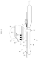
FIG. 7 , the distance from the front end (left side inFIG. 7 ) of theoutlet 23 to thecamera 42 is expressed by a symbol 'a'. Abeam irradiation surface 55, to which ultrasonic waves are irradiated to acquire an image, is provided at the front (left side inFIG. 7 ) of theprobe 10. The distance from the interface between thebeam irradiation surface 55 and theneedle 30 to the front end of theoutlet 23 is expressed by a symbol 'b'. - The distance from a zero position (left side in
FIG. 7 ), which is a reference position of thefirst indicator 44, to thecamera 42 of themeasurement unit 40 to sense a position is expressed by a symbol 'c'. A value of 'c' may be acquired through themeasurement unit 40. The distance from the zero position, which is the reference position of thefirst indicator 44, to the front end (left side inFIG. 7 ) of theneedle 30 is expressed by a symbol 'e'. - Values of 'a', 'b' and 'e' may be kinematically calculated or acquired through real measurement. These values are stored in the
controller 50. The value of 'c' may be acquired through the operation of themeasurement unit 40 according to movement of theneedle 30. This value is transmitted to thecontroller 50. - The distance 'd' from the interface between the
beam irradiation surface 55 and theneedle 30 to the front end (left side inFIG. 7 ) of theneedle 30 may be acquired based on these values. That is, a symbol 'd' is a length of theneedle 30 displayed only on thebeam irradiation surface 55. A value of 'd' may be acquired using the following expression: 'd=(c+e)-(a+b)'. - The front end (left side in
FIG. 7 ) of theprobe 10 is a part contacting a target to be tested, i.e. a human body. The distance from the front end of theprobe 10 to the front end of theneedle 30 is a length of theneedle 30 inserted into the human body, which is expressed by a symbol 'g'. - The length from the front end of the
probe 10 to the front end of theoutlet 23 may be expressed by a symbol 'f'. A value of 'f' may be kinematically calculated or acquired through real measurement. Consequently, the length g of the needle inserted into the human body is calculated using the following expression: 'g=(b+d)-f'. - Values of 'b' and 'f' are stored in the controller. The expression to calculate the value of 'd' is substituted into the expression to calculate the value of 'g' to derive the following expression: 'g=(c+e)-(a+f)'.
- These calculation expressions and methods may be used in a mechanical measurement unit operating in a contact fashion as well as
optical measurement units FIGS. 8-16 ) to measure the movement distance of theneedle 30. - Hereinafter, a
treatment device 2 according to another embodiment of the present disclosure will be described with reference to the accompanying drawings. For convenience of description, components of this embodiment identical in construction and operation to those of the previous embodiment shown inFIGS. 1 to 8 are denoted by the same reference numerals, and a detailed description thereof will be omitted. - According to the embodiments shown in
FIGS. 9 and10 , ameasurement unit 70 of thetreatment device 2 includes afirst indicator 44 for indicating length information at the outside of aneedle 30, acamera 42 for capturing and transmitting thefirst indicator 44 to acontroller 50 as an image signal, and a firstoptical sensor 72 for measuring movement of thefirst indicator 44 by transmitting and receiving light. - The first
optical sensor 72 includes a light emitting part for irradiating light to theneedle 30 and a light receiving part for sensing light reflected from theneedle 30. - Any suitable light emitting devices, including a light emitting diode (LED), may be used as the light emitting part of the first
optical sensor 72. An electric device to receive and convert light reflected from theneedle 30 or thefirst indicator 44 into an electric signal may be used as the light receiving part of the firstoptical sensor 72. - An optical sensor used in an optical mouse may be used as the first
optical sensor 72. The optical sensor may cooperate with thecamera 42 to measure a movement distance of theneedle 30. - A value measured by the first
optical sensor 72 may be transmitted to thecontroller 50. The value measured by the firstoptical sensor 72 may be analyzed by a digital signal processing chip (DSPC) to calculate a movement distance of theneedle 30. The value themn may be transmitted to thecontroller 50. - In this embodiment, the
treatment device 2 measures a movement distance of theneedle 30 using thecamera 42 and the firstoptical sensor 72, thereby more accurately measuring the movement distance of theneedle 30. - In a state in which the front end of the
needle 30 is placed in theoutlet 23 of theneedle guide 20, as shown inFIG. 9 , thefirst indicator 44 is captured by thecamera 42. - As the
needle 30 is withdrawn through theoutlet 23, as shown inFIG. 10 , thefirst indicator 44 moves with theneedle 30. - The
camera 42 captures thefirst indicator 44 and transmits images on a per frame basis to thecontroller 50. The firstoptical sensor 72 measures a movement distance of theneedle 30 and transmits a measured value to thecontroller 50. - The
controller 50 calculates the movement distance of theneedle 30 using the number ofindicator bands 46 captured by thecamera 42 and an interval between theindicator bands 46. - In some embodiments, the movement distance of the
needle 30 is calculated based on a value measured by the firstoptical sensor 72 and is set to an average of the measured values acquired by thecamera 42 and the firstoptical sensor 72. - The
controller 50 may provide the movement distance of theneedle 30 to a user through adisplay unit 66. Alternatively, an additional speaker may be used to provide the movement distance of theneedle 30 to the user. - The user easily confirms the movement distance of the
needle 30 through thedisplay unit 66, thereby safely sampling or treating a target. - Hereinafter, a
treatment device 3 according to another embodiment of the present disclosure will be described with reference to the accompanying drawings. For convenience of description, components of this embodiment identical in construction and operation to those of the previous embodiment shown inFIGS. 1 to 8 are denoted by the same reference numerals, and a detailed description thereof will be omitted. - In the embodiment shown in
FIGS. 11 and12 , ameasurement unit 80 of thetreatment device 3 includes anirradiation unit 82 for irradiating light of a predetermined wavelength at a predetermined time interval, asecond indicator 84 having a pattern formed of a paint, and reflecting the light of the predetermined wavelength among the light irradiated from theirradiation unit 82, anoptical sensor 86 for sensing the light of the wavelength reflected from the second indicator, and a secondoptical sensor 88 for measuring movement of thesecond indicator 84. - The
measurement unit 80 may be provided in aninlet 22, through which aneedle 30 is inserted into aneedle guide 20, in aprobe 10 adjacent to theinlet 22, or the middle 25 of theneedle guide 20. - Any irradiation device may be used as the
irradiation unit 82 as long as the irradiation device is suitable for irradiating light of a specific wavelength to theneedle 30. - In one embodiment, the
irradiation unit 82 may continuously irradiate light of a predetermined wavelength or irradiate light of a predetermined wavelength at a predetermined time interval. Thesecond indicator 84 includes a paint reflecting light of a specific wavelength. Thesecond indicator 84 is provided at the rear side (right side inFIG. 10 ) of theneedle 30 to detour around an insertion part of theneedle 30, which is inserted into a human body. - The
second indicator 84 may be provided at the outside of theneedle 30 using various methods, such as printing, application and attachment. The paint is provided at thesecond indicator 84 at a predetermined interval to repeatedly reflect and block light irradiated from theirradiation unit 82 toward theoptical sensor 86. - The light reflected from the
second indicator 84 is received by theoptical sensor 86 and converted into an electric signal, which is transmitted to thecontroller 50. The movement distance of theneedle 30 may be measured using theirradiation unit 82, thesecond indicator 84 and theoptical sensor 86. In addition, the secondoptical sensor 88 is provided to measure the movement distance of theneedle 30. - In the embodiment shown in
FIG. 11 , the secondoptical sensor 88 according to one embodiment has the same construction and operation as the firstoptical sensor 72 according to the previous embodiment shown inFIGS. 9 and10 , and therefore, a detailed description thereof will be omitted. - In a state in which the front end of the
needle 30 is placed in theoutlet 23 of theneedle guide 20, as shown inFIG. 11 , theirradiation unit 82 irradiates light of a specific wavelength to thesecond indicator 84. The light of the specific wavelength reflected from thesecond indicator 84 is received by theoptical sensor 86 and converted into an electric signal, which is transmitted to thecontroller 50. - As the
needle 30 is withdrawn through theoutlet 23, as shown inFIG. 12 , thesecond indicator 84 moves with theneedle 30. According to the movement of thesecond indicator 84, the light from theirradiation unit 82 is repeatedly reflected and non-reflected to theoptical sensor 86. Theoptical sensor 86 generates an electric signal based on when the light is received and when the light is not received. - The
controller 50 analyzes the signal of thesecond indicator 84 measured by theoptical sensor 86 to calculate the movement distance of theneedle 30. - In one embodiment, the movement distance of the
needle 30 is calculated based on a value measured by the secondoptical sensor 88 and is set to an average of the measured values acquired by theoptical sensor 86 and the secondoptical sensor 88. Hereinafter, atreatment device 4 according to another embodiment of the present disclosure, however, not forming part of the present invention, will be described with reference to the accompanying drawings. For convenience of description, components of this embodiment identical in construction and operation to those of the previous embodiment shown inFIGS. 1 to 8 are denoted by the same reference numerals, and a detailed description thereof will be omitted. - In the embodiment shown in
FIGS. 13 and14 , ameasurement unit 90 of thetreatment device 4 includes a magneticfield generation unit 92 for generating a magnetic field at a region through which aneedle 30 extends and acoil sensor 94 interlocked with theneedle 30 for sensing change of the magnetic field caused while passing through the magneticfield generation unit 92. - The magnetic
field generation unit 92 is provided in aneedle guide 20 or aprobe 10 for generating a magnetic field in aninlet 96 of theneedle guide 20. - The magnetic
field generation unit 92 may be formed in various shapes, such as a cylindrical shape. The magneticfield generation unit 92 generates different magnetic fields depending upon positions at which thecoil sensor 94, which moves with theneedle 30, is located. - The
coil sensor 94, which moves with theneedle 30, is connected to thecontroller 50 to measure change of the magnetic field caused while passing through the magnetic field generated by the magneticfield generation unit 92 and to transmit the measured change of the magnetic field to thecontroller 50. - Any suitable electromagnetic device may be used as the magnetic
field generation unit 92 and thecoil sensor 94 as long as power is supplied to the electromagnetic device in a wired or wireless fashion so that the electromagnetic device generates a magnetic field. - When the front end of the
needle 30 is placed in theoutlet 23 of theneedle guide 20, as shown inFIG. 13 , thecoil sensor 94 is introduced into the magneticfield generation unit 92 to sense change of a magnetic field. - The
coil sensor 94 senses the change of the magnetic field and transmits a measured value to thecontroller 50. Consequently, thecontroller 50 recognizes the positions of thecoil sensor 94 and theneedle 30 at which thecoil sensor 94 is provided. - As the
needle 30 is withdrawn through theoutlet 23, as shown inFIG. 14 , thecoil sensor 94 moves with theneedle 30. Thecoil sensor 94 measures magnetic fields changed depending upon the position thereof while moving along the inside of the magneticfield generation unit 92. The measured value is converted into an electric signal, which is transmitted to thecontroller 50. - The
controller 50 analyzes the magnetic field change signal measured by thecoil sensor 94 to calculate the movement distance of theneedle 30 and to provide the result to a user through adisplay unit 66. - Hereinafter, a
treatment device 5 according to another embodiment of the present disclosure, however, not forming part of the present invention, will be described with reference to the accompanying drawings. For convenience of description, components of this embodiment identical in construction and operation to those of the previous embodiment shown inFIGS. 1 to 8 are denoted by the same reference numerals, and a detailed description thereof will be omitted. - A
measurement unit 100 of thetreatment device 5 measures a movement distance of aneedle 30 using electromagnetic resonance (EMR). - In the embodiment shown in
FIGS. 15 and16 , themeasurement unit 100 includes aresonance circuit 102 interlocked with theneedle 30 and aresonance sensor 104, provided at a region through which theneedle 30 extends, to transmit and receive electric waves to and from theresonance circuit 102 to measure the movement distance of theneedle 30. - The
resonance sensor 104 is provided in aneedle guide 20 or aprobe 10. Any suitable electronic device may be used as theresonance sensor 104 as long as the electronic device transmits and receive an electromagnetic signal to and from theresonance circuit 102. - The
resonance sensor 104 may be formed in any suitable shapes. One example of a suitable shape is a cylindrical shape. - Power is supplied to the
resonance sensor 104, which is fixedly provided. Power is not supplied to theresonance circuit 102, which moves with theneedle 30. - The
resonance sensor 104 includes a loop coil and a transmitting and receiving swap circuit. Theresonance circuit 102 includes a coil and a condenser. - The
resonance sensor 104 receives electric waves generated from theresonance circuit 102, which moves with theneedle 30, to measure the movement distance of theneedle 30. A value measured by theresonance sensor 104 is converted into an electric signal, which is transmitted to thecontroller 50. - When the front end of the
needle 30 is placed in theoutlet 23 of theneedle guide 20, theresonance circuit 102 is introduced into theresonance sensor 104. - In other embodiments, the
resonance sensor 104 is operated in a transmitting mode and in a receiving mode. In the transmitting mode, electric waves generated by the loop coil of theresonance sensor 104 are received by the coil of theresonance circuit 102, and the condenser is charged with induced voltage generated by the electric waves. In the receiving mode, no electric waves are transmitted from the loop coil, and theresonance circuit 102 performs free oscillation. - As current flows in the coil of the
resonance circuit 102, predetermined electric waves are generated by the coil. Induced voltage is generated by the loop coil of theresonance sensor 104, which receives the electric waves. A value measured by theresonance sensor 104 is converted into an electric signal, which is transmitted to thecontroller 50. - The
resonance sensor 104 receives different electric waves caused by theresonance circuit 102, which moves in theresonance sensor 104 along with theneedle 30. Such a signal is transmitted to thecontroller 50, which calculates the movement distance of theresonance circuit 102 and theneedle 30, in which theresonance circuit 102 is provided. The result is provided to a user through adisplay unit 66. - As described above, the
treatment device needle 30 in a noncontact fashion. Consequently, contamination of theneedle 30 is prevented, and the movement distance of theneedle 30 is accurately measured, thereby improving stability of biopsy. - Also, the
measurement unit needle 30, theneedle guide 20 and theprobe 10. Consequently, no additional space is needed, thereby improving space utilization. - A treatment device according to an embodiment of the present disclosure may further include a
needle sensing unit 120 to determine whether theneedle 30 has reached areference position 110. Themeasurement unit needle sensing unit 120 to measure the movement distance of theneedle 30. - The reference position means a position at which the measurement unit begins measurement when the needle reaches the position.
- Hereinafter, the treatment further including the
needle sensing unit 120 will be described in detail. For convenience of description, this embodiment includes themeasurement unit 40 of the previous embodiment shown inFIGS. 1 to 8 . - In this embodiment, the
reference position 110 is provided below thecamera 42. When thefirst indicator 44, which moves with theneedle 30, reaches thereference position 110, thecamera 42 is driven. - A contact type sensor or a noncontact type sensor may be used as the
needle sensing unit 120, which drives thecamera 42. In one embodiment, theneedle sensing unit 120 includes arecognition member 122 provided at the outside of theneedle 30 and arecognition sensor 124 to recognize therecognition member 122 to drive theneedle sensing unit 120. - The
recognition member 122 may be formed in any suitable shape as long as therecognition member 122 is recognized by theneedle sensing unit 120. - In this embodiment, the
recognition member 122 is disposed at the outside of theneedle 30, and is band-shaped. Consequently, therecognition member 122 is easily recognized by theneedle sensing unit 120 irrespective of directivity of theneedle 30. - The
recognition sensor 124 is operated in a contact or noncontact fashion to recognize therecognition member 122. In this embodiment, therecognition sensor 124 recognizes therecognition member 122 through transmission and reception of light. Consequently, operational reliability of therecognition sensor 124 is secured although therecognition sensor 124 is repeatedly used. - The distance between the
recognition sensor 124 and thecamera 42 is equal to that between therecognition member 122 and thefirst indicator 44. When therecognition member 122 is recognized by therecognition sensor 124, therefore, thecamera 42 measures thefirst indicator 44 having reached thereference position 110 in an initialized state. - As shown in
FIG. 8 , thecontroller 50 calculates a movement distance of theneedle 30 based on a value measured by themeasurement unit 40, and an ultrasonic image signal measured by theprobe 10 is also transmitted to thecontroller 50. - Also, the
manipulation panel 64, which allows a user to input a manipulation signal, is connected to thecontroller 50 to transmit a signal to thecontroller 50. Thecontroller 50 synthesizes and outputs signals from theprobe 10, themeasurement unit 40 and themanipulation panel 64 to thedisplay unit 66. - The
controller 50 may be disposed at one or more selected from among theprobe 10, theneedle guide 20 and themain unit 60. - Hereinafter, the operation of the treatment device according to another embodiment of the present disclosure will be described in detail with reference to the accompanying drawings.
- As shown in
FIG. 18 and20 , theneedle 30 is moved toward theinlet 22 of theneedle guide 20. Subsequently, as shown inFIG. 21 , theneedle 30 is inserted through theinlet 22 and is moved along theguide pipe 21. - When the
recognition member 122 is recognized by therecognition sensor 124 in a state in which the front end of theneedle 30 is placed in theoutlet 23 of theneedle guide 20, theneedle sensing unit 120 transmits a measured signal to thecontroller 50, which transmits a drive signal to thecamera 42 of themeasurement unit 40. - Alternatively, the
recognition sensor 124 may directly transmit a drive signal to thecamera 42 to drive the camera, and theindicator bands 46 of thefirst indicator 44 are captured by thecamera 42. - As the
needle 30 is withdrawn through theoutlet 23, as shown inFIGS. 19 and22 , thefirst indicator 44 moves with theneedle 30. - The
camera 42 captures thefirst indicator 44 and transmits images on a per frame basis to thecontroller 50. Thecontroller 50 compares an image pattern signal transmitted from thecamera 42 with a stored image pattern signal to measure a movement distance of theneedle 30. - Alternatively, the number of the
indicator bands 46 captured by thecamera 42 may be multiplied by an interval between theindicator bands 46 for measuring the movement distance of theneedle 30. Thecontroller 50 calculates the movement distance of theneedle 30 based on a value measured by thecamera 42 and provides the result to a user. Thecontroller 50 may provide the movement distance of theneedle 30 to the user through thedisplay unit 66. Alternatively, an additional speaker may be used to provide the movement distance of theneedle 30 to the user via audio signals. - The user easily confirms the movement distance of the
needle 30 through thedisplay unit 66, thereby more safely sampling or treating a target. - Any suitable calculation expressions and methods may be used to calculate the length of the
needle 30 inserted into a human body using the treatment device according to this embodiment. The method previously explained with reference toFIG. 7 may be used. - In the treatment device with the above-stated construction, the
measurement unit 40 measures length information of theneedle 30 based on the operation of theneedle sensing unit 120 to determine whether theneedle 30 has reached thereference position 110. Consequently, contamination of theneedle 30 is prevented, and the movement distance of theneedle 30 is accurately measured, thereby improving stability of biopsy. - Although this embodiment adopts the
measurement unit 40 of the previous embodiment shown inFIGS. 1 to 8 , the operation of themeasurement units - In the above, medical treatment devices were described; however, embodiments of the present disclosure may be applied to biopsy in other fields.
- As is apparent from the above description, in the treatment device according to the embodiments of the present disclosure, the movement distance of the needle is sensed in a noncontact fashion, and the measurement unit measures length information of the needle based on the operation of the needle sensing unit to determine whether the needle has reached the reference position. Consequently, contamination of the needle is prevented, and the movement distance of the needle is accurately measured, thereby improving stability of biopsy.
- Also, the measurement unit is selectively provided in the needle, the needle guide and the probe. Consequently, no additional space is needed, thereby improving space utilization.
Claims (7)
- A treatment device comprising:a probe (10) for acquiring an image of a target using ultrasonic waves;a needle guide (20) provided in the probe (10); anda needle (30) movable along the needle guide (20);characterized in that the treatment device further comprises:a measurement unit (40, 70, 80, 90, 100) for sensing a movement distance of the needle (30) without having a mechanical contact with the needle (30); anda controller (50) for calculating the movement distance of the needle (30) based on a value measured by the measurement unit (40, 70, 80, 90, 100),wherein the measurement unit (40) comprises: a first indicator (44) formed at an outside of the needle (30) for indicating length information; and a camera (42) for capturing the first indicator (44) and for transmitting the first indicator (44) to the controller (50) as an image signal.
- The treatment device according to claim 1, wherein the first indicator (44) has a color or pattern varying according to the length information of the needle (30).
- The treatment device according to claim 1, wherein the controller (50) is disposed at any one selected from the probe (10), the needle guide (20) and a main unit (60).
- The treatment device according to claim 1, further comprising:a needle sensing unit (120) for determining whether the needle (30) has reached a reference position,wherein the measurement unit (40, 70, 80, 90, 100) is driven based on a determination of the needle sensing unit (120).
- The treatment device according to claim 4, wherein the needle sensing unit (120) comprises:a recognition member (122) provided at an outside of the needle (30); anda recognition sensor (124) for driving the needle sensing unit (40, 70, 80) by recognizing the recognition member (122).
- The treatment device according to claim 5, wherein the recognition member (120) is band-shaped.
- The treatment device according to claim 5, wherein a distance between the recognition sensor (124) and the camera (42) is equal to a distance between the recognition member (122) and the first indicator (44).
Applications Claiming Priority (2)
| Application Number | Priority Date | Filing Date | Title |
|---|---|---|---|
| KR20110006978 | 2011-01-24 | ||
| KR20110006977 | 2011-01-24 |
Publications (2)
| Publication Number | Publication Date |
|---|---|
| EP2478855A1 EP2478855A1 (en) | 2012-07-25 |
| EP2478855B1 true EP2478855B1 (en) | 2016-09-07 |
Family
ID=45495822
Family Applications (1)
| Application Number | Title | Priority Date | Filing Date |
|---|---|---|---|
| EP12151483.0A Not-in-force EP2478855B1 (en) | 2011-01-24 | 2012-01-18 | Treatment device |
Country Status (3)
| Country | Link |
|---|---|
| US (1) | US20120190987A1 (en) |
| EP (1) | EP2478855B1 (en) |
| KR (1) | KR101925143B1 (en) |
Families Citing this family (15)
| Publication number | Priority date | Publication date | Assignee | Title |
|---|---|---|---|---|
| JP2015016300A (en) * | 2013-06-13 | 2015-01-29 | キヤノン株式会社 | Biopsy support apparatus and biopsy support method |
| CA2928414A1 (en) * | 2013-10-24 | 2015-04-30 | Suman K. MULUMUDI | Devices and methods for measuring anatomic regions |
| US8880151B1 (en) * | 2013-11-27 | 2014-11-04 | Clear Guide Medical, Llc | Surgical needle for a surgical system with optical recognition |
| US10470824B2 (en) | 2014-01-22 | 2019-11-12 | BK Medical Holding Company | Imaging apparatus and interventional instrument event mapper |
| US20150297308A1 (en) * | 2014-04-18 | 2015-10-22 | Enterogauge, Llc | Enteroscope measuring device |
| US10413368B2 (en) | 2014-08-18 | 2019-09-17 | G-coder Systems AB | Arrangement for minimal invasive intervention |
| EP3009091A1 (en) * | 2014-10-17 | 2016-04-20 | Imactis | Medical system for use in interventional radiology |
| TW201617035A (en) * | 2014-11-07 | 2016-05-16 | 伊達醫療器材科技股份有限公司 | A equipment of using pressure detect to locate needle for medical purposes |
| EP3067236B1 (en) * | 2014-12-19 | 2018-02-21 | Application Solutions (Electronics and Vision) Limited | Image capture assembly and image capture system including an image capture assembly |
| US10321847B2 (en) * | 2014-12-30 | 2019-06-18 | Siemens Medical Solutions Usa, Inc. | Integrated tracking system for endocavity imaging |
| DE102015104821A1 (en) * | 2015-03-27 | 2016-09-29 | Medineering Gmbh | Surgical instrument, system, arm and procedure |
| CN105496519B (en) * | 2015-12-31 | 2018-10-30 | 精微视达医疗科技(武汉)有限公司 | A kind of puncture navigation system under B ultrasound guiding |
| KR101931747B1 (en) | 2016-10-28 | 2019-03-13 | 삼성메디슨 주식회사 | Biopsy apparatus and method for operating the same |
| EP3820397A1 (en) * | 2018-07-10 | 2021-05-19 | Intuitive Surgical Operations, Inc. | Systems for sensing presence of medical tools |
| CN114403925A (en) * | 2022-01-21 | 2022-04-29 | 山东黄金职业病防治院 | Breast cancer ultrasonic detection system |
Family Cites Families (4)
| Publication number | Priority date | Publication date | Assignee | Title |
|---|---|---|---|---|
| JP3723663B2 (en) * | 1997-07-15 | 2005-12-07 | フクダ電子株式会社 | Ultrasonic diagnostic equipment |
| US8123691B2 (en) * | 2003-08-19 | 2012-02-28 | Kabushiki Kaisha Toshiba | Ultrasonic diagnostic apparatus for fixedly displaying a puncture probe during 2D imaging |
| US20050171522A1 (en) * | 2004-01-30 | 2005-08-04 | Christopherson Mark A. | Transurethral needle ablation system with needle position indicator |
| US10039527B2 (en) * | 2009-05-20 | 2018-08-07 | Analogic Canada Corporation | Ultrasound systems incorporating spatial position sensors and associated methods |
-
2012
- 2012-01-18 EP EP12151483.0A patent/EP2478855B1/en not_active Not-in-force
- 2012-01-20 US US13/355,077 patent/US20120190987A1/en not_active Abandoned
- 2012-01-20 KR KR1020120006987A patent/KR101925143B1/en active IP Right Grant
Also Published As
| Publication number | Publication date |
|---|---|
| KR20120085680A (en) | 2012-08-01 |
| EP2478855A1 (en) | 2012-07-25 |
| US20120190987A1 (en) | 2012-07-26 |
| KR101925143B1 (en) | 2018-12-04 |
Similar Documents
| Publication | Publication Date | Title |
|---|---|---|
| EP2478855B1 (en) | Treatment device | |
| EP2478856B1 (en) | Treatment device | |
| US9468395B2 (en) | Medical unit and method for improving examination and treatment workflows | |
| US7074185B2 (en) | Ultrasonic diagnostic apparatus, ultrasonic probe and navigation method for acquisition of ultrasonic image | |
| US6587709B2 (en) | Method of and imaging ultrasound system for determining the position of a catheter | |
| US8527033B1 (en) | Systems and methods for assisting with internal positioning of instruments | |
| US20060258895A1 (en) | Catheter, catheter device and imaging diagnostic apparatus | |
| US10026191B2 (en) | Multi-imaging modality navigation system | |
| JP6061602B2 (en) | Insertion system having an insertion part and an insertion member | |
| CN109564132A (en) | Imaging method and device | |
| JP3365981B2 (en) | Endoscope shape detector | |
| WO2006135875A2 (en) | Active template guide plate and system and method for utilizing same | |
| US9720512B2 (en) | Device and method for the gesture-controlled setting of setting variables on an X-ray source | |
| JP7270658B2 (en) | Image recording device, method of operating image recording device, and image recording program | |
| CN102548471A (en) | Optical probe system with increased scanning speed | |
| CN106061417B (en) | Registration device for interventional procedures | |
| KR102203928B1 (en) | Method for detecting position of micro robot using ultra wiide band impulse radar and therefore device | |
| JP2013514116A (en) | Optical respiratory state sensor | |
| JP2008036248A (en) | Vertebral pedicular arch probe navigation system and navigation method | |
| KR101931747B1 (en) | Biopsy apparatus and method for operating the same | |
| KR101551914B1 (en) | Buit-in image senser speckle endoscope | |
| Placidi et al. | Review on patents about magnetic localisation systems for in vivo catheterizations | |
| KR101611449B1 (en) | Method for Controlling Medical Imaging Apparatus Having Probe and Medical Imaging Apparatus Thereof | |
| US20160338779A1 (en) | Imaging Apparatus and Interventional Instrument Event Mapper | |
| KR20200017889A (en) | Untrasound dianognosis apparatus |
Legal Events
| Date | Code | Title | Description |
|---|---|---|---|
| PUAI | Public reference made under article 153(3) epc to a published international application that has entered the european phase |
Free format text: ORIGINAL CODE: 0009012 |
|
| AK | Designated contracting states |
Kind code of ref document: A1 Designated state(s): AL AT BE BG CH CY CZ DE DK EE ES FI FR GB GR HR HU IE IS IT LI LT LU LV MC MK MT NL NO PL PT RO RS SE SI SK SM TR |
|
| AX | Request for extension of the european patent |
Extension state: BA ME |
|
| 17P | Request for examination filed |
Effective date: 20130125 |
|
| 17Q | First examination report despatched |
Effective date: 20140523 |
|
| GRAP | Despatch of communication of intention to grant a patent |
Free format text: ORIGINAL CODE: EPIDOSNIGR1 |
|
| INTG | Intention to grant announced |
Effective date: 20160425 |
|
| GRAS | Grant fee paid |
Free format text: ORIGINAL CODE: EPIDOSNIGR3 |
|
| GRAA | (expected) grant |
Free format text: ORIGINAL CODE: 0009210 |
|
| AK | Designated contracting states |
Kind code of ref document: B1 Designated state(s): AL AT BE BG CH CY CZ DE DK EE ES FI FR GB GR HR HU IE IS IT LI LT LU LV MC MK MT NL NO PL PT RO RS SE SI SK SM TR |
|
| REG | Reference to a national code |
Ref country code: GB Ref legal event code: FG4D |
|
| REG | Reference to a national code |
Ref country code: CH Ref legal event code: EP |
|
| REG | Reference to a national code |
Ref country code: IE Ref legal event code: FG4D |
|
| REG | Reference to a national code |
Ref country code: AT Ref legal event code: REF Ref document number: 826113 Country of ref document: AT Kind code of ref document: T Effective date: 20161015 |
|
| REG | Reference to a national code |
Ref country code: DE Ref legal event code: R096 Ref document number: 602012022539 Country of ref document: DE |
|
| REG | Reference to a national code |
Ref country code: FR Ref legal event code: PLFP Year of fee payment: 6 |
|
| REG | Reference to a national code |
Ref country code: NL Ref legal event code: FP |
|
| REG | Reference to a national code |
Ref country code: LT Ref legal event code: MG4D |
|
| PG25 | Lapsed in a contracting state [announced via postgrant information from national office to epo] |
Ref country code: RS Free format text: LAPSE BECAUSE OF FAILURE TO SUBMIT A TRANSLATION OF THE DESCRIPTION OR TO PAY THE FEE WITHIN THE PRESCRIBED TIME-LIMIT Effective date: 20160907 Ref country code: HR Free format text: LAPSE BECAUSE OF FAILURE TO SUBMIT A TRANSLATION OF THE DESCRIPTION OR TO PAY THE FEE WITHIN THE PRESCRIBED TIME-LIMIT Effective date: 20160907 Ref country code: FI Free format text: LAPSE BECAUSE OF FAILURE TO SUBMIT A TRANSLATION OF THE DESCRIPTION OR TO PAY THE FEE WITHIN THE PRESCRIBED TIME-LIMIT Effective date: 20160907 Ref country code: NO Free format text: LAPSE BECAUSE OF FAILURE TO SUBMIT A TRANSLATION OF THE DESCRIPTION OR TO PAY THE FEE WITHIN THE PRESCRIBED TIME-LIMIT Effective date: 20161207 Ref country code: LT Free format text: LAPSE BECAUSE OF FAILURE TO SUBMIT A TRANSLATION OF THE DESCRIPTION OR TO PAY THE FEE WITHIN THE PRESCRIBED TIME-LIMIT Effective date: 20160907 |
|
| REG | Reference to a national code |
Ref country code: AT Ref legal event code: MK05 Ref document number: 826113 Country of ref document: AT Kind code of ref document: T Effective date: 20160907 |
|
| PG25 | Lapsed in a contracting state [announced via postgrant information from national office to epo] |
Ref country code: ES Free format text: LAPSE BECAUSE OF FAILURE TO SUBMIT A TRANSLATION OF THE DESCRIPTION OR TO PAY THE FEE WITHIN THE PRESCRIBED TIME-LIMIT Effective date: 20160907 Ref country code: SE Free format text: LAPSE BECAUSE OF FAILURE TO SUBMIT A TRANSLATION OF THE DESCRIPTION OR TO PAY THE FEE WITHIN THE PRESCRIBED TIME-LIMIT Effective date: 20160907 Ref country code: LV Free format text: LAPSE BECAUSE OF FAILURE TO SUBMIT A TRANSLATION OF THE DESCRIPTION OR TO PAY THE FEE WITHIN THE PRESCRIBED TIME-LIMIT Effective date: 20160907 Ref country code: GR Free format text: LAPSE BECAUSE OF FAILURE TO SUBMIT A TRANSLATION OF THE DESCRIPTION OR TO PAY THE FEE WITHIN THE PRESCRIBED TIME-LIMIT Effective date: 20161208 |
|
| PG25 | Lapsed in a contracting state [announced via postgrant information from national office to epo] |
Ref country code: EE Free format text: LAPSE BECAUSE OF FAILURE TO SUBMIT A TRANSLATION OF THE DESCRIPTION OR TO PAY THE FEE WITHIN THE PRESCRIBED TIME-LIMIT Effective date: 20160907 Ref country code: RO Free format text: LAPSE BECAUSE OF FAILURE TO SUBMIT A TRANSLATION OF THE DESCRIPTION OR TO PAY THE FEE WITHIN THE PRESCRIBED TIME-LIMIT Effective date: 20160907 |
|
| PG25 | Lapsed in a contracting state [announced via postgrant information from national office to epo] |
Ref country code: IS Free format text: LAPSE BECAUSE OF FAILURE TO SUBMIT A TRANSLATION OF THE DESCRIPTION OR TO PAY THE FEE WITHIN THE PRESCRIBED TIME-LIMIT Effective date: 20170107 Ref country code: BE Free format text: LAPSE BECAUSE OF FAILURE TO SUBMIT A TRANSLATION OF THE DESCRIPTION OR TO PAY THE FEE WITHIN THE PRESCRIBED TIME-LIMIT Effective date: 20160907 Ref country code: SM Free format text: LAPSE BECAUSE OF FAILURE TO SUBMIT A TRANSLATION OF THE DESCRIPTION OR TO PAY THE FEE WITHIN THE PRESCRIBED TIME-LIMIT Effective date: 20160907 Ref country code: CZ Free format text: LAPSE BECAUSE OF FAILURE TO SUBMIT A TRANSLATION OF THE DESCRIPTION OR TO PAY THE FEE WITHIN THE PRESCRIBED TIME-LIMIT Effective date: 20160907 Ref country code: PL Free format text: LAPSE BECAUSE OF FAILURE TO SUBMIT A TRANSLATION OF THE DESCRIPTION OR TO PAY THE FEE WITHIN THE PRESCRIBED TIME-LIMIT Effective date: 20160907 Ref country code: PT Free format text: LAPSE BECAUSE OF FAILURE TO SUBMIT A TRANSLATION OF THE DESCRIPTION OR TO PAY THE FEE WITHIN THE PRESCRIBED TIME-LIMIT Effective date: 20170109 Ref country code: AT Free format text: LAPSE BECAUSE OF FAILURE TO SUBMIT A TRANSLATION OF THE DESCRIPTION OR TO PAY THE FEE WITHIN THE PRESCRIBED TIME-LIMIT Effective date: 20160907 Ref country code: BG Free format text: LAPSE BECAUSE OF FAILURE TO SUBMIT A TRANSLATION OF THE DESCRIPTION OR TO PAY THE FEE WITHIN THE PRESCRIBED TIME-LIMIT Effective date: 20161207 Ref country code: SK Free format text: LAPSE BECAUSE OF FAILURE TO SUBMIT A TRANSLATION OF THE DESCRIPTION OR TO PAY THE FEE WITHIN THE PRESCRIBED TIME-LIMIT Effective date: 20160907 |
|
| REG | Reference to a national code |
Ref country code: DE Ref legal event code: R097 Ref document number: 602012022539 Country of ref document: DE |
|
| PLBE | No opposition filed within time limit |
Free format text: ORIGINAL CODE: 0009261 |
|
| STAA | Information on the status of an ep patent application or granted ep patent |
Free format text: STATUS: NO OPPOSITION FILED WITHIN TIME LIMIT |
|
| PG25 | Lapsed in a contracting state [announced via postgrant information from national office to epo] |
Ref country code: DK Free format text: LAPSE BECAUSE OF FAILURE TO SUBMIT A TRANSLATION OF THE DESCRIPTION OR TO PAY THE FEE WITHIN THE PRESCRIBED TIME-LIMIT Effective date: 20160907 |
|
| 26N | No opposition filed |
Effective date: 20170608 |
|
| PG25 | Lapsed in a contracting state [announced via postgrant information from national office to epo] |
Ref country code: SI Free format text: LAPSE BECAUSE OF FAILURE TO SUBMIT A TRANSLATION OF THE DESCRIPTION OR TO PAY THE FEE WITHIN THE PRESCRIBED TIME-LIMIT Effective date: 20160907 |
|
| REG | Reference to a national code |
Ref country code: CH Ref legal event code: PL |
|
| GBPC | Gb: european patent ceased through non-payment of renewal fee |
Effective date: 20170118 |
|
| PG25 | Lapsed in a contracting state [announced via postgrant information from national office to epo] |
Ref country code: MC Free format text: LAPSE BECAUSE OF FAILURE TO SUBMIT A TRANSLATION OF THE DESCRIPTION OR TO PAY THE FEE WITHIN THE PRESCRIBED TIME-LIMIT Effective date: 20160907 |
|
| PG25 | Lapsed in a contracting state [announced via postgrant information from national office to epo] |
Ref country code: CH Free format text: LAPSE BECAUSE OF NON-PAYMENT OF DUE FEES Effective date: 20170131 Ref country code: LI Free format text: LAPSE BECAUSE OF NON-PAYMENT OF DUE FEES Effective date: 20170131 |
|
| REG | Reference to a national code |
Ref country code: IE Ref legal event code: MM4A |
|
| PG25 | Lapsed in a contracting state [announced via postgrant information from national office to epo] |
Ref country code: LU Free format text: LAPSE BECAUSE OF NON-PAYMENT OF DUE FEES Effective date: 20170118 Ref country code: GB Free format text: LAPSE BECAUSE OF NON-PAYMENT OF DUE FEES Effective date: 20170118 |
|
| REG | Reference to a national code |
Ref country code: FR Ref legal event code: PLFP Year of fee payment: 7 |
|
| PG25 | Lapsed in a contracting state [announced via postgrant information from national office to epo] |
Ref country code: IE Free format text: LAPSE BECAUSE OF NON-PAYMENT OF DUE FEES Effective date: 20170118 |
|
| PG25 | Lapsed in a contracting state [announced via postgrant information from national office to epo] |
Ref country code: MT Free format text: LAPSE BECAUSE OF NON-PAYMENT OF DUE FEES Effective date: 20170118 |
|
| PG25 | Lapsed in a contracting state [announced via postgrant information from national office to epo] |
Ref country code: AL Free format text: LAPSE BECAUSE OF FAILURE TO SUBMIT A TRANSLATION OF THE DESCRIPTION OR TO PAY THE FEE WITHIN THE PRESCRIBED TIME-LIMIT Effective date: 20160907 |
|
| PG25 | Lapsed in a contracting state [announced via postgrant information from national office to epo] |
Ref country code: HU Free format text: LAPSE BECAUSE OF FAILURE TO SUBMIT A TRANSLATION OF THE DESCRIPTION OR TO PAY THE FEE WITHIN THE PRESCRIBED TIME-LIMIT; INVALID AB INITIO Effective date: 20120118 |
|
| PG25 | Lapsed in a contracting state [announced via postgrant information from national office to epo] |
Ref country code: CY Free format text: LAPSE BECAUSE OF NON-PAYMENT OF DUE FEES Effective date: 20160907 |
|
| PG25 | Lapsed in a contracting state [announced via postgrant information from national office to epo] |
Ref country code: MK Free format text: LAPSE BECAUSE OF FAILURE TO SUBMIT A TRANSLATION OF THE DESCRIPTION OR TO PAY THE FEE WITHIN THE PRESCRIBED TIME-LIMIT Effective date: 20160907 |
|
| PGFP | Annual fee paid to national office [announced via postgrant information from national office to epo] |
Ref country code: NL Payment date: 20191206 Year of fee payment: 9 |
|
| PGFP | Annual fee paid to national office [announced via postgrant information from national office to epo] |
Ref country code: FR Payment date: 20191209 Year of fee payment: 9 |
|
| PG25 | Lapsed in a contracting state [announced via postgrant information from national office to epo] |
Ref country code: TR Free format text: LAPSE BECAUSE OF FAILURE TO SUBMIT A TRANSLATION OF THE DESCRIPTION OR TO PAY THE FEE WITHIN THE PRESCRIBED TIME-LIMIT Effective date: 20160907 |
|
| PGFP | Annual fee paid to national office [announced via postgrant information from national office to epo] |
Ref country code: IT Payment date: 20200114 Year of fee payment: 9 Ref country code: DE Payment date: 20191205 Year of fee payment: 9 |
|
| REG | Reference to a national code |
Ref country code: DE Ref legal event code: R119 Ref document number: 602012022539 Country of ref document: DE |
|
| REG | Reference to a national code |
Ref country code: NL Ref legal event code: MM Effective date: 20210201 |
|
| PG25 | Lapsed in a contracting state [announced via postgrant information from national office to epo] |
Ref country code: NL Free format text: LAPSE BECAUSE OF NON-PAYMENT OF DUE FEES Effective date: 20210201 Ref country code: FR Free format text: LAPSE BECAUSE OF NON-PAYMENT OF DUE FEES Effective date: 20210131 |
|
| PG25 | Lapsed in a contracting state [announced via postgrant information from national office to epo] |
Ref country code: DE Free format text: LAPSE BECAUSE OF NON-PAYMENT OF DUE FEES Effective date: 20210803 |
|
| PG25 | Lapsed in a contracting state [announced via postgrant information from national office to epo] |
Ref country code: IT Free format text: LAPSE BECAUSE OF NON-PAYMENT OF DUE FEES Effective date: 20210118 |