US10026191B2 - Multi-imaging modality navigation system - Google Patents
Multi-imaging modality navigation system Download PDFInfo
- Publication number
- US10026191B2 US10026191B2 US15/039,621 US201315039621A US10026191B2 US 10026191 B2 US10026191 B2 US 10026191B2 US 201315039621 A US201315039621 A US 201315039621A US 10026191 B2 US10026191 B2 US 10026191B2
- Authority
- US
- United States
- Prior art keywords
- imaging data
- volumetric
- imaging
- tissue
- data
- Prior art date
- Legal status (The legal status is an assumption and is not a legal conclusion. Google has not performed a legal analysis and makes no representation as to the accuracy of the status listed.)
- Active
Links
Images


Classifications
-
- G—PHYSICS
- G06—COMPUTING; CALCULATING OR COUNTING
- G06T—IMAGE DATA PROCESSING OR GENERATION, IN GENERAL
- G06T7/00—Image analysis
- G06T7/30—Determination of transform parameters for the alignment of images, i.e. image registration
- G06T7/33—Determination of transform parameters for the alignment of images, i.e. image registration using feature-based methods
-
- A—HUMAN NECESSITIES
- A61—MEDICAL OR VETERINARY SCIENCE; HYGIENE
- A61B—DIAGNOSIS; SURGERY; IDENTIFICATION
- A61B8/00—Diagnosis using ultrasonic, sonic or infrasonic waves
- A61B8/08—Detecting organic movements or changes, e.g. tumours, cysts, swellings
- A61B8/0833—Detecting organic movements or changes, e.g. tumours, cysts, swellings involving detecting or locating foreign bodies or organic structures
- A61B8/0841—Detecting organic movements or changes, e.g. tumours, cysts, swellings involving detecting or locating foreign bodies or organic structures for locating instruments
-
- A—HUMAN NECESSITIES
- A61—MEDICAL OR VETERINARY SCIENCE; HYGIENE
- A61B—DIAGNOSIS; SURGERY; IDENTIFICATION
- A61B8/00—Diagnosis using ultrasonic, sonic or infrasonic waves
- A61B8/08—Detecting organic movements or changes, e.g. tumours, cysts, swellings
- A61B8/0833—Detecting organic movements or changes, e.g. tumours, cysts, swellings involving detecting or locating foreign bodies or organic structures
- A61B8/085—Detecting organic movements or changes, e.g. tumours, cysts, swellings involving detecting or locating foreign bodies or organic structures for locating body or organic structures, e.g. tumours, calculi, blood vessels, nodules
-
- A—HUMAN NECESSITIES
- A61—MEDICAL OR VETERINARY SCIENCE; HYGIENE
- A61B—DIAGNOSIS; SURGERY; IDENTIFICATION
- A61B8/00—Diagnosis using ultrasonic, sonic or infrasonic waves
- A61B8/48—Diagnostic techniques
- A61B8/483—Diagnostic techniques involving the acquisition of a 3D volume of data
-
- G—PHYSICS
- G06—COMPUTING; CALCULATING OR COUNTING
- G06T—IMAGE DATA PROCESSING OR GENERATION, IN GENERAL
- G06T7/00—Image analysis
- G06T7/30—Determination of transform parameters for the alignment of images, i.e. image registration
- G06T7/37—Determination of transform parameters for the alignment of images, i.e. image registration using transform domain methods
Definitions
- the following generally relates to imaging and finds particular application to a multi-imaging modality navigation system.
- An ultrasound imaging system includes a transducer array that transmits an ultrasound beam into an examination field of view.
- structure e.g., of a sub-portion of an object or subject
- sub-portions of the beam are attenuated, scattered, and/or reflected off the structure, with some of the reflections (echoes) traversing back towards the transducer array.
- the transducer array receives echoes, which are processed to generate an image of the sub-portion of the object or subject. The image is visually displayed.
- Ultrasound imaging is used in a wide range of medical and non-medical applications.
- An example of a medical application is ultrasound guided biopsy.
- a biopsy is a procedure in which a small sample(s) of tissue of interest (e.g., prostate, lung, breast, etc.) is removed for subsequent examination for abnormalities such as cancer cells.
- tissue of interest e.g., prostate, lung, breast, etc.
- a needle is inserted through the skin and advanced to the target tissue where the sample(s) is taken.
- a biopsy typically is performed in response to finding a lump, abnormal physical enlargement of tissue, etc.
- ultrasound is used to assist a clinician with locating and/or navigating the needle to the tissue of interest.
- a non-limiting approach is described in Pelissier et al., Ser. No. 12/775,403, filed May 6, 2010, and entitled “Freehand Ultrasound Imaging Systems and Method for Guiding Find Elongate Instruments,” which is incorporated herein by reference in its entirety.
- electro-magnetic sensors are affixed to both the ultrasound probe and a needle instrument, and communicate with a position tracking system, which monitors the position and orientation thereof.
- the transducer probe is placed against the patient and 2D data is acquired.
- the location of the probe (and the needle where the needle instrument is affixed to the probe), relative to the ultrasound image, is determined from the tracking sensors on the probe.
- the location of the needle, relative to the ultrasound image is determined from the tracking sensors on the needle instrument. Both scenarios allow the clinician to determine the location of the probe and/or the needle in 3D space.
- MRI systems generally, are capable of capturing high resolution, 3D data that is rich in internal structure and features.
- Ultrasound in comparison, is capable of capturing low to medium-high resolution data sets, both two-dimensional and three-dimensional, at high acquisition rates that can support real-time interaction.
- the 3D MRI image data is acquired before the biopsy. Then, during the biopsy, the 2D ultrasound data is fused with the 3D MRI data.
- electro-mechanical sensor based tracking systems often require expensive equipment and manual procedures in order to extract critical information concerning the presence and extent of malignancies. Even the latest ultrasound and MRI fusion-based systems require expensive hardware-based tracking technology. Furthermore, currently, the clinician will take more samples than is absolutely necessary, in both target tissues and surrounding tissue due to uncertainty in both correlation and tracking. This may lead to increased procedure time and patient discomfort.
- a method in one aspect, includes obtaining first 3D imaging data for a volume of interest.
- the first 3D imaging data includes structural imaging data and a target tissue of interest.
- the method further includes obtaining 2D imaging data.
- the 2D imaging data includes structural imaging data for a plane of the volume of interest.
- the plane includes at least three fiducial markers of a set of fiducial markers.
- the method further includes locating a plane, including location and orientation, in the first 3D imaging data that corresponds to the plane of the 2D imaging data by matching the at least three fiducial markers with corresponding fiducial markers identified in the first 3D imaging data and using the map.
- the method further includes visually displaying the first 3D imaging data with the 2D imaging data superimposed over at the corresponding plane located in the first 3D imaging data.
- a multi-modality navigation system in another aspect, includes an imaging data processor that processes at least one of 3D volumetric non-US imaging data or 3D volumetric US imaging data, producing at least one of first and second image data in which structure represented in the at least one of 3D volumetric non-US imaging data and the 3D volumetric US imaging data is visually enhanced.
- the multi-modality navigation system further includes a 3D US imaging data to 3D non-US imaging data mapping generator that fuses the processed at least one of the 3D volumetric non-US imaging data and the 3D volumetric US imaging data and generates a mapping there between based on the fused processed at least one of the 3D volumetric non-US imaging data and the 3D volumetric US imaging data.
- the mapping further maps markers identified in the 3D volumetric non-US imaging data to the 3D US imaging data.
- the mapping further maps target tissue identified in the 3D volumetric non-US imaging data to the 3D US imaging data.
- the multi-modality navigation system further includes a 2D US imaging data to 3D non-US imaging data combiner that combines 2D US imaging data with the 3D non-US imaging data. The combiner places the 2D US imaging data at a location and orientation in the 3D non-US imaging data corresponding to a same plane based on the mapping and the markers.
- the multi-modality navigation system further includes a display that concurrently displays the combined 3D non-US imaging data and the 2D US imaging data.
- a computer readable storage medium is encoded with computer executable instructions, which, when executed by a processor, causes the processor to: track a location of an US probe with respect to non-US 3D imaging data based on a mapping between a US 3D imaging data and the non-US 3D imaging and a set of fiducials representing structure visually present in both the US 3D imaging data and the non-US 3D imaging and current US 2D imaging data.
- the computer executable instructions when executed by the processor, further cause the processor to: suggest a path for the US probe from a current location of the US probe to target tissue of interest based at least on the mapping.
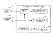
- FIG. 1 schematically illustrates an example multi-modality navigation system
- FIG. 2 schematically illustrates an example imaging data processor, a 3D US imaging data to 3D non-US imaging data mapping generator, and a 2D US imaging data to 3D non-US imaging data combiner of the multi-modality navigation system of FIG. 1 ;
- FIG. 3 schematically illustrates an example US imaging system with an instrument navigation guide affixed to an US probe thereof;
- FIG. 4 schematically illustrates an example hand-held US imaging system with an instrument navigation guide affixed externally thereto;
- FIG. 5 schematically illustrates example hand-held US imaging system with an instrument navigation guide integrated therein;
- FIG. 6 illustrates an example method for multi-modality navigation.
- the following describes an approach for tracking a location of an US imaging probe with respect to a volume of interest during an imaging procedure using on 2D imaging data acquired with the US imaging probe and previously acquired 3D imaging data of the volume of interest based on a set of fiducial markers that are visually present in both the 2D imaging data and the 3D imaging data.
- the following also describes an approach for suggesting movement of the probe to move the probe such that target tissue of interest is in the field of view of the probe.
- This approach facilitates locating target tissue(s) of interest in connection with applications such as a biopsy of the prostate gland.
- the tracking and/or movement is achieved without use of any external tracking system (e.g., electro-mechanical sensors) and/or segmentation of tissue from in the 2D imaging data and/or the 3D imaging data.
- the approach described herein can mitigate hardware-based tracking, provide superior and faster location identification, and reduce overall procedure cost and procedure time.
- FIG. 1 schematically illustrates an example multi-modality navigation system 100 in connection with two or more imaging systems 102 .
- the illustrated multi-modality navigation system 100 receives imaging data from the two or more imaging systems 102 .
- the two or more imaging systems 102 include at least one non-US imaging system 104 and an US imaging system 106 .
- the at least one non-US imaging system 104 generates 3D structural imaging data.
- structural imaging data refers to imaging data that includes voxels with values that correspond to scanned structure such as, for example, organs, bone, tumor, etc., as opposed to functional imaging data in which the voxels are indicative of function such as, for example, changes in metabolism, agent uptake/washout, etc.
- the non-US imaging system 104 is, e.g., an MRI imaging system, a CT imaging system, etc.
- the non-US 3D imaging data is obtained from a data repository such as a radiology information system (RIS), a hospital information system (HIS), an electronic medical record (EMR), and/or other data repository.
- RIS radiology information system
- HIS hospital information system
- EMR electronic medical record
- the non-US 3D imaging data may include 3D imaging data from more than one imaging system.
- the US imaging system 106 generates 3D and 2D structural US imaging data.
- the US imaging data generally, will have lower resolution than the non-US imaging data.
- the US imaging system 106 is employed during a procedure to generate initial 3D imaging data and then subsequent 2D imaging data or subsequent 2D imaging data and subsequent 3D imaging data. For the latter, e.g., this may include generating 3D US imaging data after a predetermined number of 2D US imaging data frames.
- 2D US imaging data is acquired at fixed time intervals (e.g., a fraction of a second), as the user guides the probe to the target locations for sampling.
- the multi-modality navigation system 100 includes an imaging data processor 108 .
- the imaging data processor 108 processes the non-US 3D imaging data and/or the US 3D imaging data. As described in greater detail below, in one instance, such processing includes visually enhancing anatomical structure represented in both the non-US 3D imaging data and/or the US 3D imaging data, rendering image data sets that are more similar, structurally, than before the processing.
- the multi-modality navigation system 100 further includes a 3D US imaging data to 3D non-US imaging data mapping generator 110 .
- the 3D US imaging data to 3D non-US imaging data mapping generator 110 generates a mapping between the 3D US imaging data and the 3D non-US imaging data. As described in greater detail below, the mapping is based on the enhanced structure and an initial set of fiducial markers identified in the 3D non-US imaging data.
- the fiducial markers may include an anatomical fiducial marker, a tissue fiducial marker, and/or fiducial marker.
- the mapping allows one or more target tissues identified in the 3D non-US imaging data to be located in the 3D US imaging data.
- the mapping also allows the initial set of fiducial markers to be located in the 3D US imaging data.
- one or more additional fiducial markers Once mapped, one or more additional fiducial markers, corresponding to structure visually present in both types of imaging data (in low, mid and high resolution) can be identified.
- the initial and/or additional fiducial markers are manually or semi-automatically identified.
- the multi-modality navigation system 100 further includes a 2D US imaging data to 3D non-US imaging data combiner 112 .
- the combiner 112 combines current 2D US imaging data with the non-US 3D imaging data. As described in greater detail below, this includes matching the fiducial markers of the 2D US imaging data with the fiducial markers in the non-US 3D imaging data, which matches the current 2D US imaging data to the plane and orientation in the non-US 3D imaging data.
- the multi-modality navigation system 100 further includes a path suggestor 114 that suggests a path from the current location of the US probe that will place the US probe at a target tissue (or other identified tissue) location at which the target tissue will be in the field of view of the US probe.
- the path is suggested based on 2D US imaging data acquired during one or more acquisition frames (store in memory 116 ), e.g., from information such as velocity, acceleration, direction, etc. of the US probe there between is derived.
- the multi-modality navigation system 100 further includes a display 118 .
- the 3D non-US imaging data is displayed with the current 2D US image data superimposed there over. This allows the user to visually see where the US probe is currently located relative to the target tissue(s) of interest identified in the non-US imaging data.
- Alphanumeric and/or graphical indicia is concurrently rendered to visually show the suggested path, including predicted direction, translation and/or rotation of the probe to position the probe so that a target tissue is in the field of view.
- the multi-modality navigation system 100 allows for tracking the location of the US probe with respect to the target tissue(s) and the 3D non-US imaging data via software, without any electro-mechanical tracking sensors affixed to the US probe. Additionally, the image data processing and fiducial markers mitigate a need for segmenting the target tissue(s) into discernible blobs or tissue and registering the blobs. Furthermore, the multi-modality navigation system 100 allows for predicting a path for the US probe to the target tissue(s) with higher confidence in less time.
- the multi-modality navigation system 100 can be implemented via one or more computer processors (e.g., a central processing unit (CPU), a microprocessor, a controller, etc.) executing one or more computer executable instructions embedded or encoded on computer readable storage medium, which excludes transitory medium, such as physical memory.
- computer processors e.g., a central processing unit (CPU), a microprocessor, a controller, etc.
- CPU central processing unit
- microprocessor e.g., a microprocessor, a controller, etc.
- computer executable instructions embedded or encoded on computer readable storage medium, which excludes transitory medium, such as physical memory.
- at least one of the computer executable instructions can alternatively be carried by a carrier wave, signal, and other transitory medium and implemented via the one or more computer processors.
- FIG. 2 schematically illustrates an example of the 3D imaging data processor 108 , the 3D US imaging data to 3D non-US imaging data mapping generator 110 , and the 2D US imaging data to 3D non-US imaging data combiner 112 .
- the 3D imaging data processor 108 processes the 3D non-US imaging data and/or the 3D US imaging data. In this example, the 3D imaging data processor 108 processes both the 3D non-US imaging data and the 3D US imaging data.
- the 3D imaging data processor 108 includes a non-US 3D imaging data processor 202 .
- the non-US 3D imaging data processor 202 includes a structure enhancer 204 .
- the structure enhancer 204 visually enhances certain structural characteristics such as edges of tissue, boundaries between structure such as tissue, etc. This can be achieved, for example, by applying a gradient operator, scaling the amplitude of the voxels values, etc.
- the non-US 3D imaging data processor 102 can include additional or alternative processing components.
- the 3D imaging data processor 108 also includes a US 3D imaging data processor 206 .
- the US 3D imaging data processor 206 includes a structure enhancer 208 and an image data re-mapper 210 .
- the structure enhancer 208 visually enhances certain structural characteristics such as edges of tissue, boundaries between tissue, etc., for example, by removing speckle, applying a gradient operator, scaling the amplitude of the voxels values, etc.
- the image data re-mapper 210 scales the US 3D imaging data to that of a size of the non-US 3D imaging data and scales the amplitude so that a total amplitude of each of the non-US 3D imaging data and the US 3D imaging data is approximately a same amplitude.
- the US 3D imaging data processor 206 can include additional or alternative processing components.
- the US 3D imaging data processor 206 enhances structure in the US 3D imaging data by de-speckling the US 3D imaging data, applying a gradient to find the edges of tissue, re-scaling the US 3D imaging data and/or the non-US 3D imaging data (e.g., so that the size of the US 3D imaging data and the size of the non-US 3D imaging data are approximately the same, and re-scaling an intensity of the US 3D imaging data and/or the non-US 3D imaging data (e.g., so that a total intensity of the non-US 3D imaging data and an intensity of the non-US 3D imaging data match).
- Such processing transforms the US 3D imaging data to a 3D frame of reference that is more similar to that of the non-US 3D imaging data.
- the 3D US imaging data to 3D non-US imaging data mapping generator 110 includes a target tissue identifier 212 .
- the target tissue identifier 212 allows a user to identify target tissue(s) of interest in the non-US 3D imaging data. This may include providing the user with tools that allow the user to manually trace the target tissue, set a seed point in the target tissue and then invoke automatic extraction, select the tissue by name and invoke automatic extraction, etc.
- the 3D US imaging data to 3D non-US imaging data mapping generator 110 further includes an initial fiducial identifier 214 that identifies the initial set of fiducial markers in the non-US 3D imaging data.
- One of more of the fiducial markers can be set manually by the user via the user input. Additionally or alternatively, one of more of the fiducial markers can be set automatically and changed, confirmed and/or rejected by the user via the user input.
- the 3D US imaging data to 3D non-US imaging data mapping generator 110 further includes an imaging data fuser 216 .
- the imaging data fuser 216 fuses the non-US 3D imaging data and the US 3D imaging data together.
- the 3D US imaging data to 3D non-US imaging data mapping generator 110 further includes a mapping component 218 .
- the mapping component 218 generates a map or mapping between the fused non-US 3D imaging data and the US 3D imaging data based on the enhanced structure and the initial set of fiducial markers.
- the map allows any location in the US 3D imaging data to be mapped to the non-US 3D imaging data.
- the map further allows the target tissue and/or one or more fiducial markers to be located in the US 3D imaging data.
- the 3D US imaging data to 3D non-US imaging data mapping generator 110 further includes a subsequent fiducial identifier 220 .
- the subsequent fiducial identifier 220 allows a user to identify one or more additional fiducial markers.
- the one or more of the fiducial markers can be set manually by the user via the user input and/or automatically and changed, confirmed and/or rejected by the user via the user input.
- the 2D US imaging data to non-US 3D imaging data combiner 112 includes a data matcher 222 .
- the data matcher 222 matches current 2D US imaging data to the non-US 3D imaging data based on the fiducial markers.
- the current 2D US imaging data is acquired so that it includes at least three of the fiducial markers.
- the data matcher 222 maps the location and orientation of the 2D US imaging data to a plane of the non-US 3D imaging data based on the at least three fiducial markers.
- At least three co-planar fiducial markers are used to match the 2D US imaging data with a plane in the 3D non-US imaging data.
- more than three co-planar anatomical fiducial markers can be used. Using more than three co-planar anatomical fiducial markers may mitigate error due to tissue deformation, which may move a fiducial marker in the 2D US imaging data so that it is no longer in alignment with the corresponding fiducial marker in the 3D non-US imaging data.
- Using more than three co-planar fiducial markers may also improve the resolution of the fit.
- the additional fiducial markers may also be co-planar.
- a fiducial marker that is in the 3D non-US imaging data but out of plane with respect to the 2D US imaging data can also be used. At least squares or other approach can be used to fit the 2D US imaging data to the 3D non-US imaging data. The fit, in one instance, optimizes a correlation between the imaging data sets.
- the 2D US imaging data to non-US 3D imaging data combiner 112 employs a similar approach to mapping the 3D US imaging data to a corresponding location and orientation in the 3D non-US imaging data.
- the 3D non-US imaging data is concurrently displayed with the 2D US imaging data at the determined location and orientation in the non-US 3D imaging data.
- a suggested path is determined as described herein and concurrently displayed.
- FIG. 3 illustrates an example of the US imaging system 106 .
- the US imaging system 106 includes a console 302 and a separate US transducer probe 304 that interfaces therewith.
- the ultrasound transducer probe 304 includes a transducer array with a plurality of transducer elements 306 .
- the transducer array can be linear, curved, and/or otherwise shaped, fully populated, sparse and/or a combination thereof, etc.
- the transducer elements 306 can be operated in 2D and/or 3D mode.
- the transducer elements 306 transmit ultrasound signals and receive echo signals.
- An instrument guide 308 such as a biopsy needle guide, is affixed to the US transducer probe 304 through a coupling 310 such as a bracket, clamp, etc.
- a coupling 310 such as a bracket, clamp, etc.
- the biopsy needle is supported in the instrument guide 308 in a retracted position until a target tissue of interest is located with the US transducer probe 304 as described herein. Then, the needle is advanced to acquire the sample of the target tissue of interest.
- Transmit circuitry 312 selectively actuates or excites one or more of the transducer elements 306 . More particularly, the transmit circuitry 312 generates a set of pulses (or a pulsed signal) that are conveyed to the transducer elements 306 . The set of pulses actuates a set of the transducer elements 306 , causing the transducer elements 306 to transmit ultrasound signals into an examination or scan field of view.
- Receive circuitry 314 receives a set of echoes (or echo signals) generated in response to the transmitted ultrasound signals.
- the echoes generally, are a result of the interaction between the emitted ultrasound signals and the object (e.g., flowing blood cells, organ cells, etc.) in the scan field of view.
- the receive circuit 314 may be configured for spatial compounding, filtering (e.g., FIR and/or IIR), and/or other echo processing.
- a beamformer 316 processes the received echoes. In B-mode, this includes applying time delays and weights to the echoes and summing the delayed and weighted echoes.
- a scan converter 318 scan converts the data for display, e.g., by converting the beamformed data to the coordinate system of a display or display region used to visually present the resulting data.
- a user interface (UI) 320 include one or more input devices (e.g., a button, a knob, a slider, etc., touchscreen and/or physical mechanical device) and/or one or more output devices (e.g., a liquid crystal display, a light emitting diode, etc.), which allows for interaction between with the system 106 .
- a display 322 visually displays the US imaging data.
- a controller 324 controls the various components of the system 106 .
- control may include actuating or exciting individual or groups of transducer elements of the transducer array 202 for an A-mode, B-mode, C-plane, and/or other data acquisition mode, steering and/or focusing the transmitted signal, etc., actuating the transducer elements 306 for steering and/or focusing the received echoes, etc.
- the US probe 304 and the display 322 are physically separate electromechanical components with respect to the console 302 .
- the US probe 304 and the display 322 communicate with the console 302 through communications paths 326 and 328 .
- the communications paths 326 and 328 can be wired (e.g., a physical cable and connectors) and/or wireless.
- FIG. 4 illustrates a variation of the US imaging system 106 .
- the console 302 includes a single housing 402 .
- the single housing 402 houses and physically supports the transducer elements 306 , the instrument guide 308 , the transmit circuitry 312 , the receive circuitry 314 , the beamformer 316 , the scan converter 318 and the controller 324 , all of which are inside the single housing 402 .
- the user interface 320 and/or the display 322 are part of the housing 402 .
- the display 322 in one instance, is a sub-portion of one of the sides of the housing 402 .
- the user interface 320 may include physical mechanical controls at other locations of the housing 402 .
- An ultrasound window 404 is also part of or integrated with the console 200 .
- the transducer elements 204 are disposed in the housing 402 behind the ultrasound window 404 and emit signals and receive echoes there through.
- the US imaging system 106 is a hand-held ultrasound apparatus, which uses internally located power, e.g., from a power source such as a battery, a capacitor, etc. to power the components therein, and/or power from an external power source.
- a power source such as a battery, a capacitor, etc.
- An example of a hand-held device are described in U.S. Pat. No. 7,699,776 to Walker et al., entitled “Intuitive Ultrasonic Imaging System and Related Method Thereof,” and filed on Mar. 6, 2003, which is incorporated herein in its entirety by reference.
- FIG. 5 illustrates a variation of FIG. 4 in which the instrument guide 308 is disposed out of the single housing 402 and affixed thereto through the coupling 310 .
- an external tracking system and/or electro-mechanical sensors can be used with the approach described herein.
- electro-mechanical sensors affixed to the instrument can be registered to the 3D non-US imaging data coordinate system and used to the track the instrument.
- FIG. 6 illustrates a method for navigating a US probe to a target tissue of interest.
- a 3D volumetric structural scan of a volume of interest is performed, generating 3D volumetric structural imaging data.
- the 3D volumetric structural imaging data is processed to visually enhance structural (e.g., edges, boundaries, etc.) represented therein.
- one or more target tissues of interest and an initial set of fiducial markers are identified in the visually enhanced 3D volumetric structural imaging data.
- a 3D volumetric US scan of the volume of interest is performed, generating 3D volumetric US imaging data.
- the 3D US volumetric structural imaging data is processed to visually enhance structural (e.g., edges, boundaries, etc.) represented therein.
- the visually enhanced non-US and US volumetric structural imaging data are fused.
- additional fiducial markers are identified in the 3D non-US imaging data of the fused imaging data.
- a 2D US scan of a plane of the volume is performed with of a US probe, generating 2D US imaging data.
- the scanned plane includes at least three co-planar fiducial makers.
- the 2D US plane is matched to a corresponding 2D plane in the 3D volumetric structural imaging data based on the fiducial markers.
- the 3D volumetric structural imaging data is displayed with the 2D US plane superimposed thereover at the location of the corresponding 2D plane.
- a path from the current location of the US probe to the target tissue is determined based on previously performed 2D US scan during the procedure.
- indicia indicating the path is concurrently superimposed over the displayed the 3D volumetric structural imaging data.
- the US probe is moved based on the suggested path, and acts 618 to 628 are repeated.
- the target tissue is in the field of view of the US probe, then at 632 , the target tissue is biopsied.
- the procedure is completed and/or no longer uses the multi-imaging modality navigation system 100 .
- the above may be implemented by way of computer readable instructions, encoded or embedded on computer readable storage medium, which, when executed by a computer processor(s), cause the processor(s) to carry out the described acts. Additionally or alternatively, at least one of the computer readable instructions is carried by a signal, carrier wave or other transitory medium.
Abstract
Description
Claims (23)
Applications Claiming Priority (1)
| Application Number | Priority Date | Filing Date | Title |
|---|---|---|---|
| PCT/US2013/072154 WO2015080716A1 (en) | 2013-11-27 | 2013-11-27 | Multi-imaging modality navigation system |
Publications (2)
| Publication Number | Publication Date |
|---|---|
| US20170169577A1 US20170169577A1 (en) | 2017-06-15 |
| US10026191B2 true US10026191B2 (en) | 2018-07-17 |
Family
ID=49780385
Family Applications (1)
| Application Number | Title | Priority Date | Filing Date |
|---|---|---|---|
| US15/039,621 Active US10026191B2 (en) | 2013-11-27 | 2013-11-27 | Multi-imaging modality navigation system |
Country Status (4)
| Country | Link |
|---|---|
| US (1) | US10026191B2 (en) |
| EP (1) | EP3074947B1 (en) |
| CN (1) | CN105874507B (en) |
| WO (1) | WO2015080716A1 (en) |
Cited By (10)
| Publication number | Priority date | Publication date | Assignee | Title |
|---|---|---|---|---|
| US10991069B2 (en) * | 2014-10-08 | 2021-04-27 | Samsung Electronics Co., Ltd. | Method and apparatus for registration of medical images |
| US11103200B2 (en) * | 2015-07-22 | 2021-08-31 | Inneroptic Technology, Inc. | Medical device approaches |
| US11179136B2 (en) | 2016-02-17 | 2021-11-23 | Inneroptic Technology, Inc. | Loupe display |
| US11259879B2 (en) | 2017-08-01 | 2022-03-01 | Inneroptic Technology, Inc. | Selective transparency to assist medical device navigation |
| US11464578B2 (en) | 2009-02-17 | 2022-10-11 | Inneroptic Technology, Inc. | Systems, methods, apparatuses, and computer-readable media for image management in image-guided medical procedures |
| US11464575B2 (en) | 2009-02-17 | 2022-10-11 | Inneroptic Technology, Inc. | Systems, methods, apparatuses, and computer-readable media for image guided surgery |
| US11481868B2 (en) | 2006-08-02 | 2022-10-25 | Inneroptic Technology, Inc. | System and method of providing real-time dynamic imagery of a medical procedure she using multiple modalities |
| US11484365B2 (en) | 2018-01-23 | 2022-11-01 | Inneroptic Technology, Inc. | Medical image guidance |
| US11684429B2 (en) | 2014-10-02 | 2023-06-27 | Inneroptic Technology, Inc. | Affected region display associated with a medical device |
| US11931117B2 (en) | 2014-12-12 | 2024-03-19 | Inneroptic Technology, Inc. | Surgical guidance intersection display |
Families Citing this family (5)
| Publication number | Priority date | Publication date | Assignee | Title |
|---|---|---|---|---|
| US11064979B2 (en) * | 2016-05-16 | 2021-07-20 | Analogic Corporation | Real-time anatomically based deformation mapping and correction |
| WO2017200521A1 (en) * | 2016-05-16 | 2017-11-23 | Analogic Corporation | Real-time sagittal plane navigation in ultrasound imaging |
| CN106923862B (en) * | 2017-03-17 | 2020-11-27 | 苏州佳世达电通有限公司 | Ultrasonic scanning guide device and ultrasonic scanning guide method |
| US10657709B2 (en) * | 2017-10-23 | 2020-05-19 | Fit3D, Inc. | Generation of body models and measurements |
| CN109009435A (en) * | 2018-08-20 | 2018-12-18 | 真健康(北京)医疗科技有限公司 | A kind of Lung neoplasm puncture navigation system |
Citations (39)
| Publication number | Priority date | Publication date | Assignee | Title |
|---|---|---|---|---|
| US5488674A (en) | 1992-05-15 | 1996-01-30 | David Sarnoff Research Center, Inc. | Method for fusing images and apparatus therefor |
| US5672877A (en) | 1996-03-27 | 1997-09-30 | Adac Laboratories | Coregistration of multi-modality data in a medical imaging system |
| US5766129A (en) | 1996-06-13 | 1998-06-16 | Aloka Co., Ltd. | Ultrasound diagnostic apparatus and method of forming an ultrasound image by the apparatus |
| US20030128801A1 (en) | 2002-01-07 | 2003-07-10 | Multi-Dimensional Imaging, Inc. | Multi-modality apparatus for dynamic anatomical, physiological and molecular imaging |
| US20030194050A1 (en) | 2002-04-15 | 2003-10-16 | General Electric Company | Multi modality X-ray and nuclear medicine mammography imaging system and method |
| US20040066909A1 (en) | 2002-10-04 | 2004-04-08 | Lonn Albert Henry Roger | Multi modality imaging methods and apparatus |
| US20040210133A1 (en) | 2003-04-15 | 2004-10-21 | Dror Nir | Method and system for selecting and recording biopsy sites in a body organ |
| DE10323008A1 (en) | 2003-05-21 | 2004-12-23 | Siemens Ag | Automatic fusion of 2D fluoroscopic C-frame X-ray images with preoperative 3D images using navigation markers, by use of a projection matrix based on a 2D fluoroscopy image and a defined reference navigation system |
| US20050027187A1 (en) | 2003-07-23 | 2005-02-03 | Karl Barth | Process for the coupled display of intra-operative and interactively and iteratively re-registered pre-operative images in medical imaging |
| US20050049502A1 (en) | 2003-08-28 | 2005-03-03 | Armin Schoisswohl | Method and apparatus for correcting a volumetric scan of an object moving at an uneven period |
| US20050249398A1 (en) | 2004-04-21 | 2005-11-10 | Ali Khamene | Rapid and robust 3D/3D registration technique |
| US6966878B2 (en) | 2003-08-28 | 2005-11-22 | Ge Medical Systems Global Technology Company, Llc | Method and apparatus for obtaining a volumetric scan of a periodically moving object |
| US20060002630A1 (en) | 2004-06-30 | 2006-01-05 | Accuray, Inc. | Fiducial-less tracking with non-rigid image registration |
| US20070270687A1 (en) | 2004-01-13 | 2007-11-22 | Gardi Lori A | Ultrasound Imaging System and Methods Of Imaging Using the Same |
| US20080009699A1 (en) | 2003-04-11 | 2008-01-10 | Georgios Sakas | Combining first and second image data of an object |
| US20080064949A1 (en) | 2003-08-08 | 2008-03-13 | Hertel Sarah R | Method and apparatus of multi-modality image fusion |
| US7483034B2 (en) | 2004-02-25 | 2009-01-27 | Siemens Medical Solutions Usa, Inc. | System and method for GPU-based 3D nonrigid registration |
| US7529392B2 (en) | 2002-11-27 | 2009-05-05 | Koninklijke Philips Electronics N.V. | Image processing system and medical examination apparatus for correlating features in medical images |
| US7639896B2 (en) | 2004-08-09 | 2009-12-29 | Carestream Health, Inc. | Multimodal image registration using compound mutual information |
| US20100036247A1 (en) | 2004-12-13 | 2010-02-11 | Masa Yamamoto | Ultrasonic diagnosis apparatus |
| US20110081063A1 (en) | 2007-09-18 | 2011-04-07 | Koelis | System and method for imaging and locating punctures under prostatic echography |
| US20110238043A1 (en) | 2010-03-25 | 2011-09-29 | Sonowand As | Attachment device for attaching a rigid body to an arbitrary medical instrument |
| WO2011148299A1 (en) | 2010-05-27 | 2011-12-01 | Koninklijke Philips Electronics N.V. | Determining the specific orientation of an object |
| US8090429B2 (en) | 2004-06-30 | 2012-01-03 | Siemens Medical Solutions Usa, Inc. | Systems and methods for localized image registration and fusion |
| US8111892B2 (en) | 2008-06-04 | 2012-02-07 | Medison Co., Ltd. | Registration of CT image onto ultrasound images |
| US20120071749A1 (en) | 2009-06-05 | 2012-03-22 | Koninklijke Philips Electronics N.V. | System and method for integrated biopsy and therapy |
| US8144951B2 (en) | 2007-05-22 | 2012-03-27 | Siemens Aktiengesellschaft | Method for data evaluation |
| US8145012B2 (en) | 2004-02-20 | 2012-03-27 | Koninklijke Philips Electronics N.V. | Device and process for multimodal registration of images |
| US8270691B2 (en) | 2007-10-09 | 2012-09-18 | Siemens Aktiengesellschaft | Method for fusing images acquired from a plurality of different image acquiring modalities |
| US20120245455A1 (en) | 2009-08-31 | 2012-09-27 | Universite Joseph Fournier | Control System and Method for Precisely Guiding a Percutaneous Needle Toward the Prostate |
| US8425418B2 (en) | 2006-05-18 | 2013-04-23 | Eigen, Llc | Method of ultrasonic imaging and biopsy of the prostate |
| US8427475B2 (en) | 2005-11-14 | 2013-04-23 | Koninklijke Philips Electronics N.V. | Silhouette blend rendering of anatomical structures |
| US8437527B2 (en) | 2010-06-16 | 2013-05-07 | Hitachi Aloka Medical, Ltd. | Ultrasound diagnostic apparatus |
| US20130121457A1 (en) * | 2011-11-16 | 2013-05-16 | Siemens Medical Solutions Usa, Inc. | Patient Positioning System |
| US8447384B2 (en) | 2008-06-20 | 2013-05-21 | Koninklijke Philips Electronics N.V. | Method and system for performing biopsies |
| US8452613B2 (en) | 2008-06-11 | 2013-05-28 | Koninklijke Philips Electronics N.V. | Multiple modality computer aided diagnostic system and method |
| US20130172739A1 (en) | 2011-03-15 | 2013-07-04 | Siemens Corporation | Multi-modal medical imaging |
| US20130170721A1 (en) * | 2011-12-29 | 2013-07-04 | Samsung Electronics Co., Ltd. | Method and apparatus for processing ultrasound image |
| US20140050375A1 (en) * | 2012-08-15 | 2014-02-20 | Clemson University | Systems and methods for image guided surgery |
Family Cites Families (5)
| Publication number | Priority date | Publication date | Assignee | Title |
|---|---|---|---|---|
| ATE481033T1 (en) | 2002-03-08 | 2010-10-15 | Univ Virginia | INTUITIVE ULTRASONIC SYSTEM AND ASSOCIATED METHOD |
| US8226562B2 (en) | 2007-08-10 | 2012-07-24 | Ultrasonix Medical Corporation | Hand-held ultrasound system having sterile enclosure |
| US9895135B2 (en) | 2009-05-20 | 2018-02-20 | Analogic Canada Corporation | Freehand ultrasound imaging systems and methods providing position quality feedback |
| JP5795769B2 (en) * | 2009-12-09 | 2015-10-14 | コーニンクレッカ フィリップス エヌ ヴェ | Method, computer program and system for combination of ultrasound and x-ray system |
| US10485513B2 (en) | 2011-01-31 | 2019-11-26 | Analogic Corporation | Ultrasound imaging apparatus |
-
2013
- 2013-11-27 EP EP13808367.0A patent/EP3074947B1/en active Active
- 2013-11-27 CN CN201380081270.3A patent/CN105874507B/en active Active
- 2013-11-27 US US15/039,621 patent/US10026191B2/en active Active
- 2013-11-27 WO PCT/US2013/072154 patent/WO2015080716A1/en active Application Filing
Patent Citations (41)
| Publication number | Priority date | Publication date | Assignee | Title |
|---|---|---|---|---|
| US5488674A (en) | 1992-05-15 | 1996-01-30 | David Sarnoff Research Center, Inc. | Method for fusing images and apparatus therefor |
| US5672877A (en) | 1996-03-27 | 1997-09-30 | Adac Laboratories | Coregistration of multi-modality data in a medical imaging system |
| US5766129A (en) | 1996-06-13 | 1998-06-16 | Aloka Co., Ltd. | Ultrasound diagnostic apparatus and method of forming an ultrasound image by the apparatus |
| US20030128801A1 (en) | 2002-01-07 | 2003-07-10 | Multi-Dimensional Imaging, Inc. | Multi-modality apparatus for dynamic anatomical, physiological and molecular imaging |
| US20030194050A1 (en) | 2002-04-15 | 2003-10-16 | General Electric Company | Multi modality X-ray and nuclear medicine mammography imaging system and method |
| US6856666B2 (en) | 2002-10-04 | 2005-02-15 | Ge Medical Systems Global Technology Company, Llc | Multi modality imaging methods and apparatus |
| US20040066909A1 (en) | 2002-10-04 | 2004-04-08 | Lonn Albert Henry Roger | Multi modality imaging methods and apparatus |
| US7529392B2 (en) | 2002-11-27 | 2009-05-05 | Koninklijke Philips Electronics N.V. | Image processing system and medical examination apparatus for correlating features in medical images |
| US20080009699A1 (en) | 2003-04-11 | 2008-01-10 | Georgios Sakas | Combining first and second image data of an object |
| US20040210133A1 (en) | 2003-04-15 | 2004-10-21 | Dror Nir | Method and system for selecting and recording biopsy sites in a body organ |
| DE10323008A1 (en) | 2003-05-21 | 2004-12-23 | Siemens Ag | Automatic fusion of 2D fluoroscopic C-frame X-ray images with preoperative 3D images using navigation markers, by use of a projection matrix based on a 2D fluoroscopy image and a defined reference navigation system |
| US20050027187A1 (en) | 2003-07-23 | 2005-02-03 | Karl Barth | Process for the coupled display of intra-operative and interactively and iteratively re-registered pre-operative images in medical imaging |
| US20080064949A1 (en) | 2003-08-08 | 2008-03-13 | Hertel Sarah R | Method and apparatus of multi-modality image fusion |
| US6966878B2 (en) | 2003-08-28 | 2005-11-22 | Ge Medical Systems Global Technology Company, Llc | Method and apparatus for obtaining a volumetric scan of a periodically moving object |
| US20050049502A1 (en) | 2003-08-28 | 2005-03-03 | Armin Schoisswohl | Method and apparatus for correcting a volumetric scan of an object moving at an uneven period |
| US20070270687A1 (en) | 2004-01-13 | 2007-11-22 | Gardi Lori A | Ultrasound Imaging System and Methods Of Imaging Using the Same |
| US8145012B2 (en) | 2004-02-20 | 2012-03-27 | Koninklijke Philips Electronics N.V. | Device and process for multimodal registration of images |
| US7483034B2 (en) | 2004-02-25 | 2009-01-27 | Siemens Medical Solutions Usa, Inc. | System and method for GPU-based 3D nonrigid registration |
| US20050249398A1 (en) | 2004-04-21 | 2005-11-10 | Ali Khamene | Rapid and robust 3D/3D registration technique |
| US8090429B2 (en) | 2004-06-30 | 2012-01-03 | Siemens Medical Solutions Usa, Inc. | Systems and methods for localized image registration and fusion |
| US20060002630A1 (en) | 2004-06-30 | 2006-01-05 | Accuray, Inc. | Fiducial-less tracking with non-rigid image registration |
| US7639896B2 (en) | 2004-08-09 | 2009-12-29 | Carestream Health, Inc. | Multimodal image registration using compound mutual information |
| US20100036247A1 (en) | 2004-12-13 | 2010-02-11 | Masa Yamamoto | Ultrasonic diagnosis apparatus |
| US8427475B2 (en) | 2005-11-14 | 2013-04-23 | Koninklijke Philips Electronics N.V. | Silhouette blend rendering of anatomical structures |
| US8425418B2 (en) | 2006-05-18 | 2013-04-23 | Eigen, Llc | Method of ultrasonic imaging and biopsy of the prostate |
| US8144951B2 (en) | 2007-05-22 | 2012-03-27 | Siemens Aktiengesellschaft | Method for data evaluation |
| US8369592B2 (en) | 2007-09-18 | 2013-02-05 | Koelis | System and method for imaging and locating punctures under prostatic echography |
| US20110081063A1 (en) | 2007-09-18 | 2011-04-07 | Koelis | System and method for imaging and locating punctures under prostatic echography |
| US8270691B2 (en) | 2007-10-09 | 2012-09-18 | Siemens Aktiengesellschaft | Method for fusing images acquired from a plurality of different image acquiring modalities |
| US8111892B2 (en) | 2008-06-04 | 2012-02-07 | Medison Co., Ltd. | Registration of CT image onto ultrasound images |
| US8452613B2 (en) | 2008-06-11 | 2013-05-28 | Koninklijke Philips Electronics N.V. | Multiple modality computer aided diagnostic system and method |
| US8447384B2 (en) | 2008-06-20 | 2013-05-21 | Koninklijke Philips Electronics N.V. | Method and system for performing biopsies |
| US20120071749A1 (en) | 2009-06-05 | 2012-03-22 | Koninklijke Philips Electronics N.V. | System and method for integrated biopsy and therapy |
| US20120245455A1 (en) | 2009-08-31 | 2012-09-27 | Universite Joseph Fournier | Control System and Method for Precisely Guiding a Percutaneous Needle Toward the Prostate |
| US20110238043A1 (en) | 2010-03-25 | 2011-09-29 | Sonowand As | Attachment device for attaching a rigid body to an arbitrary medical instrument |
| WO2011148299A1 (en) | 2010-05-27 | 2011-12-01 | Koninklijke Philips Electronics N.V. | Determining the specific orientation of an object |
| US8437527B2 (en) | 2010-06-16 | 2013-05-07 | Hitachi Aloka Medical, Ltd. | Ultrasound diagnostic apparatus |
| US20130172739A1 (en) | 2011-03-15 | 2013-07-04 | Siemens Corporation | Multi-modal medical imaging |
| US20130121457A1 (en) * | 2011-11-16 | 2013-05-16 | Siemens Medical Solutions Usa, Inc. | Patient Positioning System |
| US20130170721A1 (en) * | 2011-12-29 | 2013-07-04 | Samsung Electronics Co., Ltd. | Method and apparatus for processing ultrasound image |
| US20140050375A1 (en) * | 2012-08-15 | 2014-02-20 | Clemson University | Systems and methods for image guided surgery |
Non-Patent Citations (10)
| Title |
|---|
| BioJet 4D Prostate Image Fusion Technology, Brochure, 2013, pp. 1-4, Geo Scan Medical, Lakewood Ranch, FL, US. |
| International Search Report fort PCT/US2013/072154 published as WO 2015/080716 A1. |
| Lindseth, Kaspersen, et al., Multimodal Image Fusion in Ultrasound-Based Neuronavigation: Improving Overview and Interpretation by Integrating Preoperative MRI with Intraoperative 3D Ultrasound, 2003, CAS Journal, Trondheim, Norway. |
| Marks, Ward, et al., Tracking of prostate biopsy sites using a 3D Ultrasound device (Artemis), Symposium, May 2010, American Urological Association, San Francisco, California, US. |
| MRI-Ultrasound Fusion Permits Targeted Biopsy for Prostate Cancer, Brochure, 2013, pp. 1-3, 13v2-04:03-13, UCLA Health, California, US. |
| Natarajan, Marks, et al., Clinical application of a 3D ultrasound-guided prostate biopsy system, Urologic Oncology: Seminars and Original Investigations 29 (2011) 334-342, UCLA, CA, USA. |
| Peters, T., Image-guidance for surgical procedures, Physics in Medicine and Biology, 51 (2006) R505-R540. |
| Sonowand Invite, Brochure, 2012, pp. 1-7, Sonowand AS, Trondheim, Norway. |
| UroNav Fusion Biopsy System, Brochure, 2013, pp. 1-3, Invivo Corp., Florida, US. |
| Weiss, Seitz, et al., MR-US Fusion for Targeted Prostate Biopsy, International Society for Magnetic Resonance in Medicine (ISMRM) Conference, Stockholm, Sweden, May 2010. |
Cited By (11)
| Publication number | Priority date | Publication date | Assignee | Title |
|---|---|---|---|---|
| US11481868B2 (en) | 2006-08-02 | 2022-10-25 | Inneroptic Technology, Inc. | System and method of providing real-time dynamic imagery of a medical procedure she using multiple modalities |
| US11464578B2 (en) | 2009-02-17 | 2022-10-11 | Inneroptic Technology, Inc. | Systems, methods, apparatuses, and computer-readable media for image management in image-guided medical procedures |
| US11464575B2 (en) | 2009-02-17 | 2022-10-11 | Inneroptic Technology, Inc. | Systems, methods, apparatuses, and computer-readable media for image guided surgery |
| US11684429B2 (en) | 2014-10-02 | 2023-06-27 | Inneroptic Technology, Inc. | Affected region display associated with a medical device |
| US10991069B2 (en) * | 2014-10-08 | 2021-04-27 | Samsung Electronics Co., Ltd. | Method and apparatus for registration of medical images |
| US11931117B2 (en) | 2014-12-12 | 2024-03-19 | Inneroptic Technology, Inc. | Surgical guidance intersection display |
| US11103200B2 (en) * | 2015-07-22 | 2021-08-31 | Inneroptic Technology, Inc. | Medical device approaches |
| US20220192611A1 (en) * | 2015-07-22 | 2022-06-23 | Inneroptic Technology, Inc. | Medical device approaches |
| US11179136B2 (en) | 2016-02-17 | 2021-11-23 | Inneroptic Technology, Inc. | Loupe display |
| US11259879B2 (en) | 2017-08-01 | 2022-03-01 | Inneroptic Technology, Inc. | Selective transparency to assist medical device navigation |
| US11484365B2 (en) | 2018-01-23 | 2022-11-01 | Inneroptic Technology, Inc. | Medical image guidance |
Also Published As
| Publication number | Publication date |
|---|---|
| CN105874507B (en) | 2019-09-27 |
| EP3074947B1 (en) | 2020-07-01 |
| EP3074947A1 (en) | 2016-10-05 |
| CN105874507A (en) | 2016-08-17 |
| WO2015080716A1 (en) | 2015-06-04 |
| US20170169577A1 (en) | 2017-06-15 |
Similar Documents
| Publication | Publication Date | Title |
|---|---|---|
| US10026191B2 (en) | Multi-imaging modality navigation system | |
| RU2510699C2 (en) | Method and system for biopsy | |
| EP3076875B1 (en) | An ultrasound system with stereo image guidance or tracking | |
| CN107106241B (en) | System for navigating to surgical instruments | |
| US9558405B2 (en) | Imaging based instrument event tracking | |
| WO2005092198A1 (en) | System for guiding a medical instrument in a patient body | |
| JP5736220B2 (en) | MEDICAL IMAGING DEVICE, MEDICAL IMAGING METHOD, AND COMPUTER PROGRAM CONTAINING CODE INSTRUCTION PROGRAMMED TO IMPLEMENT THE METHOD | |
| US11071518B2 (en) | Imaging apparatus for biopsy or brachytherapy | |
| Mauri et al. | Virtual navigator automatic registration technology in abdominal application | |
| EP2853200B1 (en) | Complex diagnostic apparatus, complex diagnostic system, ultrasound diagnostic apparatus, x-ray diagnostic apparatus and complex diagnostic image-generating method | |
| US20190219693A1 (en) | 3-D US Volume From 2-D Images From Freehand Rotation and/or Translation of Ultrasound Probe | |
| CN115811961A (en) | Three-dimensional display method and ultrasonic imaging system | |
| US20160278746A1 (en) | Real-time tracking for mri-guided breast biopsy | |
| US20180263577A1 (en) | Method for optimising the position of a patient's body part relative to an imaging device | |
| EP3017766B1 (en) | Ultrasound imaging apparatus and control method thereof | |
| KR20130110544A (en) | The method and apparatus for indicating a medical equipment on an ultrasound image | |
| US10470824B2 (en) | Imaging apparatus and interventional instrument event mapper | |
| US20230138666A1 (en) | Intraoperative 2d/3d imaging platform | |
| US20170281135A1 (en) | Image Registration Fiducials |
Legal Events
| Date | Code | Title | Description |
|---|---|---|---|
| AS | Assignment |
Owner name: ANALOGIC CORPORATION, MASSACHUSETTS Free format text: ASSIGNMENT OF ASSIGNORS INTEREST;ASSIGNORS:ACCOMANDO, NICHOLAS A;LIEBLICH, DAVID;O'CONNOR, JOHN P;AND OTHERS;SIGNING DATES FROM 20140214 TO 20140221;REEL/FRAME:038728/0724 |
|
| AS | Assignment |
Owner name: MIDCAP FINANCIAL TRUST, MARYLAND Free format text: SECURITY INTEREST;ASSIGNORS:ANALOGIC CORPORATION;SOUND TECHNOLOGY, INC.;REEL/FRAME:046414/0277 Effective date: 20180622 |
|
| STCF | Information on status: patent grant |
Free format text: PATENTED CASE |
|
| AS | Assignment |
Owner name: ANALOGIC CORPORATION, MASSACHUSETTS Free format text: RELEASE BY SECURED PARTY;ASSIGNOR:MIDCAP FINANCIAL TRUST;REEL/FRAME:051566/0144 Effective date: 20200121 Owner name: BK MEDICAL HOLDING COMPANY, INC., MASSACHUSETTS Free format text: ASSIGNMENT OF ASSIGNORS INTEREST;ASSIGNOR:ANALOGIC CORPORATION;REEL/FRAME:051567/0179 Effective date: 20180930 Owner name: MIDCAP FINANCIAL TRUST, MARYLAND Free format text: SECURITY INTEREST;ASSIGNOR:BK MEDICAL HOLDING COMPANY, INC.;REEL/FRAME:051569/0525 Effective date: 20200121 |
|
| AS | Assignment |
Owner name: BK MEDICAL HOLDING COMPANY, INC., MASSACHUSETTS Free format text: RELEASE BY SECURED PARTY;ASSIGNOR:MIDCAP FINANCIAL TRUST;REEL/FRAME:058456/0749 Effective date: 20211221 |
|
| MAFP | Maintenance fee payment |
Free format text: PAYMENT OF MAINTENANCE FEE, 4TH YEAR, LARGE ENTITY (ORIGINAL EVENT CODE: M1551); ENTITY STATUS OF PATENT OWNER: LARGE ENTITY Year of fee payment: 4 |
|
| AS | Assignment |
Owner name: TRUIST BANK, AS COLLATERAL AGENT, GEORGIA Free format text: SECURITY INTEREST;ASSIGNOR:ANALOGIC CORPORATION;REEL/FRAME:064954/0027 Effective date: 20230914 |