EP2477841B1 - Kraftfahrzeugsitz mit einem sitzteil das zum bilden eines stauraumes geeignet ist - Google Patents
Kraftfahrzeugsitz mit einem sitzteil das zum bilden eines stauraumes geeignet ist Download PDFInfo
- Publication number
- EP2477841B1 EP2477841B1 EP10734276.8A EP10734276A EP2477841B1 EP 2477841 B1 EP2477841 B1 EP 2477841B1 EP 10734276 A EP10734276 A EP 10734276A EP 2477841 B1 EP2477841 B1 EP 2477841B1
- Authority
- EP
- European Patent Office
- Prior art keywords
- seat
- seat portion
- motor vehicle
- complementary
- portion element
- Prior art date
- Legal status (The legal status is an assumption and is not a legal conclusion. Google has not performed a legal analysis and makes no representation as to the accuracy of the status listed.)
- Not-in-force
Links
Images
Classifications
-
- B—PERFORMING OPERATIONS; TRANSPORTING
- B60—VEHICLES IN GENERAL
- B60N—SEATS SPECIALLY ADAPTED FOR VEHICLES; VEHICLE PASSENGER ACCOMMODATION NOT OTHERWISE PROVIDED FOR
- B60N2/00—Seats specially adapted for vehicles; Arrangement or mounting of seats in vehicles
- B60N2/24—Seats specially adapted for vehicles; Arrangement or mounting of seats in vehicles for particular purposes or particular vehicles
- B60N2/30—Non-dismountable or dismountable seats storable in a non-use position, e.g. foldable spare seats
- B60N2/3081—Seats convertible into parts of the seat cushion or the back-rest or disapppearing therein, e.g. for children
- B60N2/3086—Disappearing in a recess of the cushion
-
- B—PERFORMING OPERATIONS; TRANSPORTING
- B60—VEHICLES IN GENERAL
- B60N—SEATS SPECIALLY ADAPTED FOR VEHICLES; VEHICLE PASSENGER ACCOMMODATION NOT OTHERWISE PROVIDED FOR
- B60N2/00—Seats specially adapted for vehicles; Arrangement or mounting of seats in vehicles
- B60N2/24—Seats specially adapted for vehicles; Arrangement or mounting of seats in vehicles for particular purposes or particular vehicles
- B60N2/26—Seats specially adapted for vehicles; Arrangement or mounting of seats in vehicles for particular purposes or particular vehicles for children
- B60N2/28—Seats readily mountable on, and dismountable from, existing seats or other parts of the vehicle
- B60N2/2866—Seats readily mountable on, and dismountable from, existing seats or other parts of the vehicle booster cushions, e.g. to lift a child to allow proper use of the conventional safety belts
-
- B—PERFORMING OPERATIONS; TRANSPORTING
- B60—VEHICLES IN GENERAL
- B60R—VEHICLES, VEHICLE FITTINGS, OR VEHICLE PARTS, NOT OTHERWISE PROVIDED FOR
- B60R7/00—Stowing or holding appliances inside vehicle primarily intended for personal property smaller than suit-cases, e.g. travelling articles, or maps
- B60R7/04—Stowing or holding appliances inside vehicle primarily intended for personal property smaller than suit-cases, e.g. travelling articles, or maps in driver or passenger space, e.g. using racks
- B60R7/043—Stowing or holding appliances inside vehicle primarily intended for personal property smaller than suit-cases, e.g. travelling articles, or maps in driver or passenger space, e.g. using racks mounted on or under a seat
Definitions
- the present invention relates to a motor vehicle seat.
- the document FR 2 724 606 A1 discloses a motor vehicle seat which comprises a seat member, which is pivotally mounted on the floor, at its rear edge.
- the seat element In the position of use, the seat element has a horizontal seating surface and two recesses, one formed in the floor and the other in the seat element, to form a storage space, under the seat element.
- a booster seat for children can be stored in this storage space.
- the booster By lifting the seat element, it is possible either to store the booster in the aforementioned storage space or to remove it for use on the seat element.
- the booster must, when in use, be placed on the seating surface of the seat element. It allows, by its thickness, to elevate a child passenger, so that it can be properly maintained on the seat, by the belt of the seat belt.
- the aforementioned storage space is very small and can not be used for luggage or other transportation, only when the booster seat is used on the seat.
- the document DE 10 2008 045 859 A1 comprises a seat element having a seating surface and which is adapted to be mounted on the floor of a motor vehicle, said seat element having two lateral sides which are connected by said seat surface and which comprise each a free edge, and wherein, in a first use position, said free edges are disposed above said seating surface.
- the present invention aims to provide a new motor vehicle seat that can store luggage or other.
- a motor vehicle seat comprising a seat element, which has a seating surface and which is adapted to be mounted on the floor of a motor vehicle, said seat member having two lateral flanks which are connected by said seat surface and which each comprise a free edge and where, in a first position of use of said seat member said free edges are disposed above said seating surface.
- said free edges are disposed below said seat surface, so as to raise said seat surface via said side flanks.
- Raising the seating surface provides a storage space below the seating surface of the seating element.
- the side flanks serve as support means to raise the seating surface.
- said free edges are able to cooperate in said first and said second position with the edge of an opening in said floor.
- the seat surface In the first position, the seat surface can thus be arranged in or under the opening, which minimizes the size of the seat.
- said seat member in said second use position, can form a booster.
- the seat member in addition to the storage it forms, can also be used to seat a child so that it is properly maintained by the seat belt for the seat of the invention.
- said seat member may comprise a complementary seat surface disposed opposite said seat surface and means for guiding the strap of a seat belt, in order to keep it in position on the seats. child passenger's thighs sitting on the complementary seating surface.
- said seat element comprises two complementary lateral flanks which extend on either side of said complementary seat surface and above said complementary seat surface, when said seat element is disposed in said second use position.
- the guide means of the strap of a safety belt can be formed at the level of the complementary lateral flanks.
- the two complementary flanks advantageously make it possible to form armrests and also ensure a good maintenance of the child on the complementary seat surface.
- said seat member comprises a rear wall substantially perpendicular to said seat surface and forming a backrest in said first use position.
- the seat of the invention may also comprise locking means of said seat member for locking said seat member in one or other of its positions of use.
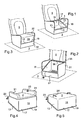
- the seat according to the invention comprises a seat member 1 which is removable and mounted on a floor 3, and a backrest 5 which is substantially perpendicular to the seat member 1.
- the seat member 1 comprises a seat surface 11, two lateral flanks 13 which are connected by the seat surface 11 and a rear wall 15 which cooperates with the backrest 5 at the lower portion thereof.
- This rear wall 15 forms a portion of the backrest at the lower back of the passenger.
- the rear wall 15 is connected to the seat surface 11 and to each of the lateral flanks 13 so as to form a continuous wall which extends substantially perpendicular to the seat surface 11.
- the seat surface 11 is disposed substantially horizontally in the vehicle and the rear wall 15 and the side flanks 13 thus extend vertically.
- Each of the flanks 13 and the rear wall 15 has a free edge 17 which has a strip or edge 19 which extends parallel to the seat surface 11 and which is directed opposite the seating surface 11, towards the outside of the seat element 1.
- the floor 3 forms a base 31 in which is mounted the seat member 1.
- This base 31 has an opening 39, which extends substantially in a horizontal plane. Behind the opening 39, the base 31 comprises a rear portion 35, substantially vertical, which is higher than the average surface of the floor 3.
- the front portion 37 of the base 31, which is located in front of the opening 39 is substantially vertical and lower than the rear portion 35.
- the rear portion 35 is disposed under the backrest 5 or may even extend vertically to form the backrest 5.
- the seating surface 11 is disposed below the free edges 17, which cooperate through the edge 19, with the edge of the opening 39 formed in the base 31.
- the seating surface 11 is thus in the base 31 and therefore locally below the surface of the floor 3.
- the side flanks 13 and the rear wall 15 connect the seat surface 11 to the base 31 so as to form a hollow seat tub in which the user can sit on the seating surface 11.
- the opening 39 has substantially the shape of the seating surface 11. Under this opening 39 are for example arranged the electric motor and the battery supply of this engine. These elements can be covered with a housing or other.
- the base 31 thus defines a storage slot which extends under the opening 39 and behind it, in the portion of the base 31, located under the backrest 5. This housing is restricted and accessible by removing the element sitting 1.
- the perimeter of the opening 39 comprises a bearing strip 38 which extends towards the center of the opening 39, over a limited width and which is able to cooperate with the edge 19 of the seat element 1
- This support strip 38 is slightly lower than the edge of the opening 39 so that, in the first and the second use position, the edge of the edge 19 abuts against the vertical surface which connects the edge of the opening 39 to the support strip 38.
- the support strip 38 forms the lower surface of a horizontal groove in which the edge 19 is housed.
- the Figure 3 represents the seat of the invention, when the seat member 1 is in the second position of use.
- the seat element 1 is turned upside down and the seat surface 11 is oriented towards the opening 39 of the base 31. It is then possible to accommodate in the storage space accessible through the opening 39, a bulky object, for example, a bag, which protrudes out of the opening 39 and which is covered in the manner of a lid by the seat element 1.
- the rear wall 15 is placed at the front portion 37 of the base 31.
- the seat member 1 therefore forms a cover for the housing storage.
- the free edges 17 are arranged downwards and are supported, via the border 19, on the support strip 38; the seat surface 11 is disposed above the free edges 17.
- the portion of the edge 19 located at the front edge of the seat member 1 (as opposed to the rear wall 15 thereof) is housed in the aforementioned groove which is located at the rear portion 35 of the base 31. Due to the shape of the seat member 1 which comprises the two sides 13 of variable height (increasing height towards the rear wall 15) and the rear wall 15, when the seat member 1 is disposed in its second position, the seat surface 11 remains substantially horizontal but returned towards the opening 39.
- the seat element 1 can form a booster.
- the surface 2 of the seat member 1 facing the seating surface 11 is disposed on top in the second use position and can be used as a complementary seating surface.
- This complementary seat surface 2 is higher than the seat surface 11 in the first use position, which allows to sit a child.
- FIGS. 4 and 5 represent particular embodiments in which the seat member 1 forms a booster when mounted in the second use position.
- the seat element comprises a complementary seat surface 2 arranged facing the seat surface 11 and guiding means 23 'of the strap of a safety belt, in order to keep it in position on the thighs of the child passenger sitting on the complementary seating surface.
- These guide means consist of a single tongue or a wire.
- the seat element 1 comprises complementary lateral flanks 21 which are substantially parallel to the lateral flanks 13 but extend in the opposite direction, that is to say above the complementary seat surface 2.
- Complementary lateral flanks 21 each comprise means for guiding the strap of a safety belt 23, which is here in the form of a tongue.
- the calves of the child sitting on the complementary seat surface 2 are arranged along the rear wall 15 of the seat element 1.
- the strap of the seat belt 23 is slid into the guide means 23 ', so as to be tense preferentially on the thighs of the child, rather than on his abdomen.
- the edge 19 abuts against the vertical surface below the edge of the opening 39 prevents inadvertent movement of the seat member 1 in one and the other of its use positions.
- the seat member 1 comprises fastening means which allow to fix it to the base 31 of the floor 3 in one or other of its use positions.
- fastening means make it possible to make the box formed by the seat element 1 tamper-proof. They also prevent the removal of the seat element 1 in case of shock, for example and thus ensures the safety of the child passenger.
- the seat element When the seat element is in the first position of use, the user can sit on the seat surface 11. His back comes into contact with the rear wall 15 and his legs protrude from the base, under this last, towards the portion of the floor 3 lower than the base 31.
- the seat element When there is no passenger, the seat element can be arranged in the second position of use. For this, simply pull the seat member 1 to the front portion 37 of the base 31 to clear the edge 19 of the groove formed in the folder 5. The user can then dispose of luggage or other in the housing accessible through the opening 39. The seat element is then returned as shown on the Figure 3 and disposed in its second use position in which it covers the luggage. In this second position of use, the seat element 1 forms a chest. It can also be used as a booster for a child passenger.
- the seat according to the invention proves to be particularly useful in a vehicle with an electric motor whose interior is particularly small and which can not include a trunk for reasons of space.
Landscapes
- Engineering & Computer Science (AREA)
- Mechanical Engineering (AREA)
- Aviation & Aerospace Engineering (AREA)
- Transportation (AREA)
- Health & Medical Sciences (AREA)
- Child & Adolescent Psychology (AREA)
- General Health & Medical Sciences (AREA)
- Seats For Vehicles (AREA)
- Passenger Equipment (AREA)
Claims (8)
- Kraftfahrzeugsitz, der ein Sitzpolsterelement (1) aufweist, das eine Sitzfläche (11) hat und das geeignet ist, um auf den Boden (3) eines Kraftfahrzeugs montiert zu werden, wobei das Sitzpolsterelement (1) zwei Seitenflanken (13) aufweist, die durch die Sitzfläche (11) verbunden sind und je einen freien Rand (17) aufweisen, und bei dem in einer ersten Nutzungsstellung des Sitzpolsterelements (1) die freien Ränder (17) über der Sitzfläche (11) angeordnet sind, dadurch gekennzeichnet, dass in einer zweiten Nutzungsstellung die freien Ränder (17) unter der Sitzfläche angeordnet sind, um die Sitzfläche (11) mittels der Seitenflanken zu erhöhen.
- Kraftfahrzeugsitz nach dem vorhergehenden Anspruch, dadurch gekennzeichnet, dass die freien Ränder (17) in der ersten und der zweiten Stellung mit dem Rand (38) einer im Boden (3) ausgesparten Öffnung (39) zusammenwirken können.
- Kraftfahrzeugsitz nach einem der vorhergehenden Ansprüche, dadurch gekennzeichnet, dass das Sitzpolsterelement (1) in der zweiten Nutzungsstellung eine Sitzerhöhung formt.
- Kraftfahrzeugsitz nach Anspruch 3, dadurch gekennzeichnet, dass das Sitzpolsterelement (1) eine komplementäre Sitzfläche (2), die gegenüber der Sitzfläche (11) angeordnet ist, und Führungseinrichtungen (23, 23') des Gurts eines Sicherheitsgurts aufweist.
- Kraftfahrzeugsitz nach Anspruch 4, dadurch gekennzeichnet, dass das Sitzpolsterelement zwei komplementäre Seitenflanken (21) aufweist, die sich zu beiden Seiten der komplementären Sitzfläche (2) und über der komplementären Sitzfläche (2) erstrecken, wenn das Sitzpolsterelement in der zweiten Nutzungsstellung angeordnet ist.
- Kraftfahrzeugsitz nach Anspruch 5, dadurch gekennzeichnet, dass die Führungseinrichtungen im Bereich der komplementären Seitenflanken geformt sind.
- Sitz nach einem der vorhergehenden Ansprüche, dadurch gekennzeichnet, dass das Sitzpolsterelement (1) eine Rückwand (15) im Wesentlichen lotrecht zur Sitzfläche (11) aufweist, die in der ersten Nutzungsstellung eine Rückenlehne formt.
- Kraftfahrzeugsitz nach einem der vorhergehenden Ansprüche, dadurch gekennzeichnet, dass er Arretiereinrichtungen des Sitzpolsterelements aufweist, um das Sitzpolsterelement (1) in der einen oder anderen seiner Nutzungsstellungen zu arretieren.
Applications Claiming Priority (2)
| Application Number | Priority Date | Filing Date | Title |
|---|---|---|---|
| FR0956339A FR2950005B1 (fr) | 2009-09-15 | 2009-09-15 | Siege de vehicule automobile comportant un element d'assise apte a former un espace de rangement. |
| PCT/FR2010/051236 WO2011033197A1 (fr) | 2009-09-15 | 2010-06-18 | Siège de véhicule automobile comportant un élément d'assise apte à former un espace de rangement |
Publications (2)
| Publication Number | Publication Date |
|---|---|
| EP2477841A1 EP2477841A1 (de) | 2012-07-25 |
| EP2477841B1 true EP2477841B1 (de) | 2013-10-02 |
Family
ID=42111998
Family Applications (1)
| Application Number | Title | Priority Date | Filing Date |
|---|---|---|---|
| EP10734276.8A Not-in-force EP2477841B1 (de) | 2009-09-15 | 2010-06-18 | Kraftfahrzeugsitz mit einem sitzteil das zum bilden eines stauraumes geeignet ist |
Country Status (5)
| Country | Link |
|---|---|
| EP (1) | EP2477841B1 (de) |
| JP (1) | JP5951488B2 (de) |
| CN (1) | CN102498013B (de) |
| FR (1) | FR2950005B1 (de) |
| WO (1) | WO2011033197A1 (de) |
Families Citing this family (6)
| Publication number | Priority date | Publication date | Assignee | Title |
|---|---|---|---|---|
| FR2997662B1 (fr) * | 2012-11-05 | 2015-01-16 | Renault Sa | Rehausseur d'assise de siege de vehicule automobile et vehicule equipe d'un tel rehausseur |
| FR3002754B1 (fr) | 2013-03-01 | 2015-03-13 | Renault Sa | Siege pour vehicule automobile comportant un element de dossier avec une partie amovible munie de moyens de rangement |
| FR3002756B1 (fr) * | 2013-03-01 | 2015-03-13 | Renault Sa | Siege de vehicule automobile a element d'assise retournable avec une ouverture pour le passage d'une base de fixation de ceinture de securite |
| FR3002755B1 (fr) | 2013-03-01 | 2015-03-13 | Renault Sa | Siege de vehicule automobile a element d'assise retournable comportant des moyens de verrouillage |
| FR3002753B1 (fr) | 2013-03-01 | 2015-03-13 | Renault Sa | Vehicule automobile comportant un siege avec un element d'assise amovible pour liberer l'acces a un renfoncement de sa structure interne |
| CN105980200B (zh) * | 2013-12-16 | 2018-05-18 | 约翰逊控制技术公司 | 车辆座椅 |
Family Cites Families (10)
| Publication number | Priority date | Publication date | Assignee | Title |
|---|---|---|---|---|
| JPS59132444U (ja) * | 1983-02-25 | 1984-09-05 | 富士重工業株式会社 | 車両用シ−ト |
| JPS59184236U (ja) * | 1983-05-26 | 1984-12-07 | 池田物産株式会社 | 座席構造 |
| JPH02220936A (ja) * | 1989-02-20 | 1990-09-04 | Mazda Motor Corp | 自動車用後部シート構造 |
| JPH0653276U (ja) * | 1992-12-28 | 1994-07-19 | デルタ工業株式会社 | 自動車用シート |
| DE9412066U1 (de) * | 1994-07-26 | 1994-09-22 | Bechthold, Werner, 67487 St Martin | Vorrichtung zum sicheren Ablegen von Gegenständen auf Kraftfahrzeugsitzen |
| FR2724606B1 (fr) * | 1994-09-20 | 1997-01-03 | Peugeot | Siege de vehicule automobile comportant, sous son assise, un volume de rangement pour un rehausseur |
| ITTO990138U1 (it) * | 1999-07-20 | 2001-01-20 | Lear Corp Italia Spa | Sedile posteriore di autoveicolo con vano porta-oggetti e coperchiodouble-face. |
| DE10329923B4 (de) * | 2003-07-02 | 2005-09-29 | Concord Gmbh | Kindersitz zur Anbringung an einen Fahrzeugsitz |
| FR2896732A1 (fr) * | 2006-01-27 | 2007-08-03 | Cera | Element d'assise comprenant une matelassure mobile montee sur un organe de pietement |
| DE102008045859A1 (de) * | 2007-09-07 | 2009-03-12 | Volkswagen Ag | Gestaltveränderbarer Fahrzeugsitz |
-
2009
- 2009-09-15 FR FR0956339A patent/FR2950005B1/fr not_active Expired - Fee Related
-
2010
- 2010-06-18 JP JP2012528406A patent/JP5951488B2/ja not_active Expired - Fee Related
- 2010-06-18 EP EP10734276.8A patent/EP2477841B1/de not_active Not-in-force
- 2010-06-18 WO PCT/FR2010/051236 patent/WO2011033197A1/fr active Application Filing
- 2010-06-18 CN CN201080041001.0A patent/CN102498013B/zh not_active Expired - Fee Related
Also Published As
| Publication number | Publication date |
|---|---|
| CN102498013A (zh) | 2012-06-13 |
| FR2950005B1 (fr) | 2011-08-26 |
| WO2011033197A1 (fr) | 2011-03-24 |
| JP5951488B2 (ja) | 2016-07-13 |
| FR2950005A1 (fr) | 2011-03-18 |
| CN102498013B (zh) | 2014-07-30 |
| EP2477841A1 (de) | 2012-07-25 |
| JP2013504467A (ja) | 2013-02-07 |
Similar Documents
| Publication | Publication Date | Title |
|---|---|---|
| EP2477841B1 (de) | Kraftfahrzeugsitz mit einem sitzteil das zum bilden eines stauraumes geeignet ist | |
| WO2011154638A1 (fr) | Dispositif de support à parois coulissantes, de façons opposées, sur des dossiers de sièges de véhicule | |
| CA2802394A1 (fr) | Dispositif d'amenagement d'un vehicule | |
| FR2921600A1 (fr) | Transporteur pliable pour vehicule automobile et son utilisation | |
| FR3002756A1 (fr) | Siege de vehicule automobile a element d'assise retournable avec une ouverture pour le passage d'une base de fixation de ceinture de securite | |
| FR3051431A1 (fr) | Support destine a ranger un engin roulant | |
| EP2371626A1 (de) | Innenraum eines Kraftfahrzeugs | |
| FR3002753A1 (fr) | Vehicule automobile comportant un siege avec un element d'assise amovible pour liberer l'acces a un renfoncement de sa structure interne | |
| EP2246217B1 (de) | Vorrichtung zum Verstauen einer Sicherheitsweste in der Kopfstütze einer Fahrzeugsitzrückenlehne | |
| FR2960491A1 (fr) | Siege pour vehicule automobile | |
| FR2908702A1 (fr) | Agencement de porte-recipient pour une tablette de vehicule automobile | |
| FR2936750A1 (fr) | "siege de vehicule automobile comportant un appui-tete pouvant etre fixe au siege dans une position de rehausseur pour enfant" | |
| FR3014781A1 (fr) | Tablette de siege formant support d'ecran tactile | |
| FR2997664A1 (fr) | Dispositif de maintien d'objet allonges dans un coffre de vehicule et vehicule dote d'un tel dispositif | |
| FR2923762A1 (fr) | Equipement articule pour siege de vehicule automobile, en particulier accoudoir | |
| EP0719513A1 (de) | Kindertrage | |
| WO2023148453A1 (fr) | Chaise haute pour enfant a tablette mobile | |
| FR3132199A1 (fr) | Chaise haute pour enfant a pietement demontable | |
| WO2022180316A1 (fr) | Agencement de coffre de vehicule, notamment automobile, equipe d'un tendelet escamotable | |
| FR2897572A1 (fr) | Vehicule automobile comportant un coffre equipe d'un dispositif de cloisonnement et de retenue d'objet | |
| FR2860459A1 (fr) | Console centrale adaptee a former un siege pour enfant | |
| EP4171999A1 (de) | Kraftfahrzeug mit armaturenbrett mit einer raumanordnung zur optimierten lagerung | |
| FR2909611A1 (fr) | Tablette arriere de vehicule | |
| FR2872464A1 (fr) | Agencement interieur de vehicule automobile comportant un element de rangement retractable, et vehicule automobile comportant un tel agencement | |
| FR3077039A1 (fr) | Panneau de porte avec dispositif d'accrochage pour accessoires |
Legal Events
| Date | Code | Title | Description |
|---|---|---|---|
| PUAI | Public reference made under article 153(3) epc to a published international application that has entered the european phase |
Free format text: ORIGINAL CODE: 0009012 |
|
| 17P | Request for examination filed |
Effective date: 20120213 |
|
| AK | Designated contracting states |
Kind code of ref document: A1 Designated state(s): AL AT BE BG CH CY CZ DE DK EE ES FI FR GB GR HR HU IE IS IT LI LT LU LV MC MK MT NL NO PL PT RO SE SI SK SM TR |
|
| DAX | Request for extension of the european patent (deleted) | ||
| GRAP | Despatch of communication of intention to grant a patent |
Free format text: ORIGINAL CODE: EPIDOSNIGR1 |
|
| RAP1 | Party data changed (applicant data changed or rights of an application transferred) |
Owner name: RENAULT S.A.S. |
|
| GRAS | Grant fee paid |
Free format text: ORIGINAL CODE: EPIDOSNIGR3 |
|
| GRAA | (expected) grant |
Free format text: ORIGINAL CODE: 0009210 |
|
| AK | Designated contracting states |
Kind code of ref document: B1 Designated state(s): AL AT BE BG CH CY CZ DE DK EE ES FI FR GB GR HR HU IE IS IT LI LT LU LV MC MK MT NL NO PL PT RO SE SI SK SM TR |
|
| REG | Reference to a national code |
Ref country code: GB Ref legal event code: FG4D Free format text: NOT ENGLISH |
|
| REG | Reference to a national code |
Ref country code: CH Ref legal event code: EP Ref country code: AT Ref legal event code: REF Ref document number: 634419 Country of ref document: AT Kind code of ref document: T Effective date: 20131015 |
|
| REG | Reference to a national code |
Ref country code: IE Ref legal event code: FG4D Free format text: LANGUAGE OF EP DOCUMENT: FRENCH |
|
| REG | Reference to a national code |
Ref country code: DE Ref legal event code: R096 Ref document number: 602010010696 Country of ref document: DE Effective date: 20131128 |
|
| REG | Reference to a national code |
Ref country code: AT Ref legal event code: MK05 Ref document number: 634419 Country of ref document: AT Kind code of ref document: T Effective date: 20131002 |
|
| REG | Reference to a national code |
Ref country code: NL Ref legal event code: VDEP Effective date: 20131002 |
|
| PG25 | Lapsed in a contracting state [announced via postgrant information from national office to epo] |
Ref country code: SI Free format text: LAPSE BECAUSE OF FAILURE TO SUBMIT A TRANSLATION OF THE DESCRIPTION OR TO PAY THE FEE WITHIN THE PRESCRIBED TIME-LIMIT Effective date: 20131002 |
|
| REG | Reference to a national code |
Ref country code: LT Ref legal event code: MG4D |
|
| PG25 | Lapsed in a contracting state [announced via postgrant information from national office to epo] |
Ref country code: IS Free format text: LAPSE BECAUSE OF FAILURE TO SUBMIT A TRANSLATION OF THE DESCRIPTION OR TO PAY THE FEE WITHIN THE PRESCRIBED TIME-LIMIT Effective date: 20140202 Ref country code: LT Free format text: LAPSE BECAUSE OF FAILURE TO SUBMIT A TRANSLATION OF THE DESCRIPTION OR TO PAY THE FEE WITHIN THE PRESCRIBED TIME-LIMIT Effective date: 20131002 Ref country code: SE Free format text: LAPSE BECAUSE OF FAILURE TO SUBMIT A TRANSLATION OF THE DESCRIPTION OR TO PAY THE FEE WITHIN THE PRESCRIBED TIME-LIMIT Effective date: 20131002 Ref country code: HR Free format text: LAPSE BECAUSE OF FAILURE TO SUBMIT A TRANSLATION OF THE DESCRIPTION OR TO PAY THE FEE WITHIN THE PRESCRIBED TIME-LIMIT Effective date: 20131002 Ref country code: FI Free format text: LAPSE BECAUSE OF FAILURE TO SUBMIT A TRANSLATION OF THE DESCRIPTION OR TO PAY THE FEE WITHIN THE PRESCRIBED TIME-LIMIT Effective date: 20131002 Ref country code: NO Free format text: LAPSE BECAUSE OF FAILURE TO SUBMIT A TRANSLATION OF THE DESCRIPTION OR TO PAY THE FEE WITHIN THE PRESCRIBED TIME-LIMIT Effective date: 20140102 Ref country code: NL Free format text: LAPSE BECAUSE OF FAILURE TO SUBMIT A TRANSLATION OF THE DESCRIPTION OR TO PAY THE FEE WITHIN THE PRESCRIBED TIME-LIMIT Effective date: 20131002 Ref country code: CZ Free format text: LAPSE BECAUSE OF FAILURE TO SUBMIT A TRANSLATION OF THE DESCRIPTION OR TO PAY THE FEE WITHIN THE PRESCRIBED TIME-LIMIT Effective date: 20131002 |
|
| PG25 | Lapsed in a contracting state [announced via postgrant information from national office to epo] |
Ref country code: CY Free format text: LAPSE BECAUSE OF FAILURE TO SUBMIT A TRANSLATION OF THE DESCRIPTION OR TO PAY THE FEE WITHIN THE PRESCRIBED TIME-LIMIT Effective date: 20131002 Ref country code: ES Free format text: LAPSE BECAUSE OF FAILURE TO SUBMIT A TRANSLATION OF THE DESCRIPTION OR TO PAY THE FEE WITHIN THE PRESCRIBED TIME-LIMIT Effective date: 20131002 Ref country code: LV Free format text: LAPSE BECAUSE OF FAILURE TO SUBMIT A TRANSLATION OF THE DESCRIPTION OR TO PAY THE FEE WITHIN THE PRESCRIBED TIME-LIMIT Effective date: 20131002 Ref country code: PL Free format text: LAPSE BECAUSE OF FAILURE TO SUBMIT A TRANSLATION OF THE DESCRIPTION OR TO PAY THE FEE WITHIN THE PRESCRIBED TIME-LIMIT Effective date: 20131002 Ref country code: AT Free format text: LAPSE BECAUSE OF FAILURE TO SUBMIT A TRANSLATION OF THE DESCRIPTION OR TO PAY THE FEE WITHIN THE PRESCRIBED TIME-LIMIT Effective date: 20131002 |
|
| PG25 | Lapsed in a contracting state [announced via postgrant information from national office to epo] |
Ref country code: PT Free format text: LAPSE BECAUSE OF FAILURE TO SUBMIT A TRANSLATION OF THE DESCRIPTION OR TO PAY THE FEE WITHIN THE PRESCRIBED TIME-LIMIT Effective date: 20140203 |
|
| REG | Reference to a national code |
Ref country code: DE Ref legal event code: R097 Ref document number: 602010010696 Country of ref document: DE |
|
| PG25 | Lapsed in a contracting state [announced via postgrant information from national office to epo] |
Ref country code: EE Free format text: LAPSE BECAUSE OF FAILURE TO SUBMIT A TRANSLATION OF THE DESCRIPTION OR TO PAY THE FEE WITHIN THE PRESCRIBED TIME-LIMIT Effective date: 20131002 |
|
| PLBE | No opposition filed within time limit |
Free format text: ORIGINAL CODE: 0009261 |
|
| STAA | Information on the status of an ep patent application or granted ep patent |
Free format text: STATUS: NO OPPOSITION FILED WITHIN TIME LIMIT |
|
| PG25 | Lapsed in a contracting state [announced via postgrant information from national office to epo] |
Ref country code: SK Free format text: LAPSE BECAUSE OF FAILURE TO SUBMIT A TRANSLATION OF THE DESCRIPTION OR TO PAY THE FEE WITHIN THE PRESCRIBED TIME-LIMIT Effective date: 20131002 Ref country code: RO Free format text: LAPSE BECAUSE OF FAILURE TO SUBMIT A TRANSLATION OF THE DESCRIPTION OR TO PAY THE FEE WITHIN THE PRESCRIBED TIME-LIMIT Effective date: 20131002 |
|
| 26N | No opposition filed |
Effective date: 20140703 |
|
| PG25 | Lapsed in a contracting state [announced via postgrant information from national office to epo] |
Ref country code: DK Free format text: LAPSE BECAUSE OF FAILURE TO SUBMIT A TRANSLATION OF THE DESCRIPTION OR TO PAY THE FEE WITHIN THE PRESCRIBED TIME-LIMIT Effective date: 20131002 |
|
| REG | Reference to a national code |
Ref country code: DE Ref legal event code: R097 Ref document number: 602010010696 Country of ref document: DE Effective date: 20140703 |
|
| PG25 | Lapsed in a contracting state [announced via postgrant information from national office to epo] |
Ref country code: MC Free format text: LAPSE BECAUSE OF FAILURE TO SUBMIT A TRANSLATION OF THE DESCRIPTION OR TO PAY THE FEE WITHIN THE PRESCRIBED TIME-LIMIT Effective date: 20131002 Ref country code: LU Free format text: LAPSE BECAUSE OF FAILURE TO SUBMIT A TRANSLATION OF THE DESCRIPTION OR TO PAY THE FEE WITHIN THE PRESCRIBED TIME-LIMIT Effective date: 20140618 |
|
| REG | Reference to a national code |
Ref country code: CH Ref legal event code: PL |
|
| REG | Reference to a national code |
Ref country code: IE Ref legal event code: MM4A |
|
| PG25 | Lapsed in a contracting state [announced via postgrant information from national office to epo] |
Ref country code: IE Free format text: LAPSE BECAUSE OF NON-PAYMENT OF DUE FEES Effective date: 20140618 Ref country code: LI Free format text: LAPSE BECAUSE OF NON-PAYMENT OF DUE FEES Effective date: 20140630 Ref country code: CH Free format text: LAPSE BECAUSE OF NON-PAYMENT OF DUE FEES Effective date: 20140630 |
|
| PG25 | Lapsed in a contracting state [announced via postgrant information from national office to epo] |
Ref country code: MT Free format text: LAPSE BECAUSE OF FAILURE TO SUBMIT A TRANSLATION OF THE DESCRIPTION OR TO PAY THE FEE WITHIN THE PRESCRIBED TIME-LIMIT Effective date: 20131002 |
|
| PG25 | Lapsed in a contracting state [announced via postgrant information from national office to epo] |
Ref country code: NO Free format text: LAPSE BECAUSE OF FAILURE TO SUBMIT A TRANSLATION OF THE DESCRIPTION OR TO PAY THE FEE WITHIN THE PRESCRIBED TIME-LIMIT Effective date: 20140101 Ref country code: SM Free format text: LAPSE BECAUSE OF FAILURE TO SUBMIT A TRANSLATION OF THE DESCRIPTION OR TO PAY THE FEE WITHIN THE PRESCRIBED TIME-LIMIT Effective date: 20131002 |
|
| REG | Reference to a national code |
Ref country code: FR Ref legal event code: PLFP Year of fee payment: 7 |
|
| PG25 | Lapsed in a contracting state [announced via postgrant information from national office to epo] |
Ref country code: BG Free format text: LAPSE BECAUSE OF FAILURE TO SUBMIT A TRANSLATION OF THE DESCRIPTION OR TO PAY THE FEE WITHIN THE PRESCRIBED TIME-LIMIT Effective date: 20131002 Ref country code: GR Free format text: LAPSE BECAUSE OF FAILURE TO SUBMIT A TRANSLATION OF THE DESCRIPTION OR TO PAY THE FEE WITHIN THE PRESCRIBED TIME-LIMIT Effective date: 20140103 |
|
| PG25 | Lapsed in a contracting state [announced via postgrant information from national office to epo] |
Ref country code: TR Free format text: LAPSE BECAUSE OF FAILURE TO SUBMIT A TRANSLATION OF THE DESCRIPTION OR TO PAY THE FEE WITHIN THE PRESCRIBED TIME-LIMIT Effective date: 20131002 Ref country code: HU Free format text: LAPSE BECAUSE OF FAILURE TO SUBMIT A TRANSLATION OF THE DESCRIPTION OR TO PAY THE FEE WITHIN THE PRESCRIBED TIME-LIMIT; INVALID AB INITIO Effective date: 20100618 Ref country code: BE Free format text: LAPSE BECAUSE OF FAILURE TO SUBMIT A TRANSLATION OF THE DESCRIPTION OR TO PAY THE FEE WITHIN THE PRESCRIBED TIME-LIMIT Effective date: 20140630 |
|
| REG | Reference to a national code |
Ref country code: FR Ref legal event code: PLFP Year of fee payment: 8 |
|
| REG | Reference to a national code |
Ref country code: FR Ref legal event code: PLFP Year of fee payment: 9 |
|
| PG25 | Lapsed in a contracting state [announced via postgrant information from national office to epo] |
Ref country code: MK Free format text: LAPSE BECAUSE OF FAILURE TO SUBMIT A TRANSLATION OF THE DESCRIPTION OR TO PAY THE FEE WITHIN THE PRESCRIBED TIME-LIMIT Effective date: 20131002 |
|
| PG25 | Lapsed in a contracting state [announced via postgrant information from national office to epo] |
Ref country code: AL Free format text: LAPSE BECAUSE OF FAILURE TO SUBMIT A TRANSLATION OF THE DESCRIPTION OR TO PAY THE FEE WITHIN THE PRESCRIBED TIME-LIMIT Effective date: 20131002 |
|
| PGFP | Annual fee paid to national office [announced via postgrant information from national office to epo] |
Ref country code: FR Payment date: 20210622 Year of fee payment: 12 Ref country code: DE Payment date: 20210618 Year of fee payment: 12 Ref country code: IT Payment date: 20210625 Year of fee payment: 12 |
|
| PGFP | Annual fee paid to national office [announced via postgrant information from national office to epo] |
Ref country code: GB Payment date: 20210625 Year of fee payment: 12 |
|
| REG | Reference to a national code |
Ref country code: DE Ref legal event code: R119 Ref document number: 602010010696 Country of ref document: DE |
|
| GBPC | Gb: european patent ceased through non-payment of renewal fee |
Effective date: 20220618 |
|
| PG25 | Lapsed in a contracting state [announced via postgrant information from national office to epo] |
Ref country code: FR Free format text: LAPSE BECAUSE OF NON-PAYMENT OF DUE FEES Effective date: 20220630 |
|
| PG25 | Lapsed in a contracting state [announced via postgrant information from national office to epo] |
Ref country code: GB Free format text: LAPSE BECAUSE OF NON-PAYMENT OF DUE FEES Effective date: 20220618 Ref country code: DE Free format text: LAPSE BECAUSE OF NON-PAYMENT OF DUE FEES Effective date: 20230103 |
|
| PG25 | Lapsed in a contracting state [announced via postgrant information from national office to epo] |
Ref country code: IT Free format text: LAPSE BECAUSE OF NON-PAYMENT OF DUE FEES Effective date: 20220618 |