EP2477198A2 - System and method for magnetization of rare-earth permanent magnets - Google Patents
System and method for magnetization of rare-earth permanent magnets Download PDFInfo
- Publication number
- EP2477198A2 EP2477198A2 EP12151018A EP12151018A EP2477198A2 EP 2477198 A2 EP2477198 A2 EP 2477198A2 EP 12151018 A EP12151018 A EP 12151018A EP 12151018 A EP12151018 A EP 12151018A EP 2477198 A2 EP2477198 A2 EP 2477198A2
- Authority
- EP
- European Patent Office
- Prior art keywords
- coil
- assembly
- coils
- superconducting
- superconducting magnet
- Prior art date
- Legal status (The legal status is an assumption and is not a legal conclusion. Google has not performed a legal analysis and makes no representation as to the accuracy of the status listed.)
- Granted
Links
- 230000005415 magnetization Effects 0.000 title claims abstract description 43
- 238000000034 method Methods 0.000 title description 9
- 229910052761 rare earth metal Inorganic materials 0.000 title description 4
- 150000002910 rare earth metals Chemical class 0.000 title description 4
- 239000000463 material Substances 0.000 claims abstract description 65
- 230000004044 response Effects 0.000 claims abstract description 14
- XEEYBQQBJWHFJM-UHFFFAOYSA-N Iron Chemical compound [Fe] XEEYBQQBJWHFJM-UHFFFAOYSA-N 0.000 claims description 18
- 238000004804 winding Methods 0.000 claims description 11
- 125000006850 spacer group Chemical group 0.000 claims description 9
- 229910052742 iron Inorganic materials 0.000 claims description 8
- 238000013459 approach Methods 0.000 description 17
- 229910001275 Niobium-titanium Inorganic materials 0.000 description 16
- RJSRQTFBFAJJIL-UHFFFAOYSA-N niobium titanium Chemical compound [Ti].[Nb] RJSRQTFBFAJJIL-UHFFFAOYSA-N 0.000 description 16
- 230000007423 decrease Effects 0.000 description 6
- 230000000712 assembly Effects 0.000 description 5
- 238000000429 assembly Methods 0.000 description 5
- 230000008569 process Effects 0.000 description 5
- 238000011065 in-situ storage Methods 0.000 description 4
- 230000003993 interaction Effects 0.000 description 4
- 239000002887 superconductor Substances 0.000 description 4
- 230000008901 benefit Effects 0.000 description 3
- 230000003247 decreasing effect Effects 0.000 description 3
- 230000004907 flux Effects 0.000 description 3
- 229910052734 helium Inorganic materials 0.000 description 3
- 239000001307 helium Substances 0.000 description 3
- SWQJXJOGLNCZEY-UHFFFAOYSA-N helium atom Chemical compound [He] SWQJXJOGLNCZEY-UHFFFAOYSA-N 0.000 description 3
- 239000007788 liquid Substances 0.000 description 3
- 239000000696 magnetic material Substances 0.000 description 3
- 230000035515 penetration Effects 0.000 description 3
- BPAABJIBIBFRST-UHFFFAOYSA-N [V].[V].[V].[Ga] Chemical compound [V].[V].[V].[Ga] BPAABJIBIBFRST-UHFFFAOYSA-N 0.000 description 2
- 239000002826 coolant Substances 0.000 description 2
- 229910001172 neodymium magnet Inorganic materials 0.000 description 2
- 230000000135 prohibitive effect Effects 0.000 description 2
- 229910000531 Co alloy Inorganic materials 0.000 description 1
- 229910000640 Fe alloy Inorganic materials 0.000 description 1
- 229910020073 MgB2 Inorganic materials 0.000 description 1
- ATJFFYVFTNAWJD-UHFFFAOYSA-N Tin Chemical compound [Sn] ATJFFYVFTNAWJD-UHFFFAOYSA-N 0.000 description 1
- PZKRHHZKOQZHIO-UHFFFAOYSA-N [B].[B].[Mg] Chemical compound [B].[B].[Mg] PZKRHHZKOQZHIO-UHFFFAOYSA-N 0.000 description 1
- 229910000828 alnico Inorganic materials 0.000 description 1
- 239000013590 bulk material Substances 0.000 description 1
- 238000006243 chemical reaction Methods 0.000 description 1
- 239000003795 chemical substances by application Substances 0.000 description 1
- 230000000694 effects Effects 0.000 description 1
- 238000003780 insertion Methods 0.000 description 1
- 230000037431 insertion Effects 0.000 description 1
- 238000003475 lamination Methods 0.000 description 1
- 238000004519 manufacturing process Methods 0.000 description 1
- 239000011159 matrix material Substances 0.000 description 1
- 230000009467 reduction Effects 0.000 description 1
- 230000000717 retained effect Effects 0.000 description 1
- 238000007493 shaping process Methods 0.000 description 1
- 238000010396 two-hybrid screening Methods 0.000 description 1
- 229910000859 α-Fe Inorganic materials 0.000 description 1
Images


Classifications
-
- H—ELECTRICITY
- H01—ELECTRIC ELEMENTS
- H01F—MAGNETS; INDUCTANCES; TRANSFORMERS; SELECTION OF MATERIALS FOR THEIR MAGNETIC PROPERTIES
- H01F6/00—Superconducting magnets; Superconducting coils
- H01F6/06—Coils, e.g. winding, insulating, terminating or casing arrangements therefor
-
- H—ELECTRICITY
- H01—ELECTRIC ELEMENTS
- H01F—MAGNETS; INDUCTANCES; TRANSFORMERS; SELECTION OF MATERIALS FOR THEIR MAGNETIC PROPERTIES
- H01F13/00—Apparatus or processes for magnetising or demagnetising
- H01F13/003—Methods and devices for magnetising permanent magnets
-
- H—ELECTRICITY
- H01—ELECTRIC ELEMENTS
- H01F—MAGNETS; INDUCTANCES; TRANSFORMERS; SELECTION OF MATERIALS FOR THEIR MAGNETIC PROPERTIES
- H01F6/00—Superconducting magnets; Superconducting coils
- H01F6/04—Cooling
-
- H—ELECTRICITY
- H02—GENERATION; CONVERSION OR DISTRIBUTION OF ELECTRIC POWER
- H02K—DYNAMO-ELECTRIC MACHINES
- H02K15/00—Methods or apparatus specially adapted for manufacturing, assembling, maintaining or repairing of dynamo-electric machines
- H02K15/02—Methods or apparatus specially adapted for manufacturing, assembling, maintaining or repairing of dynamo-electric machines of stator or rotor bodies
- H02K15/03—Methods or apparatus specially adapted for manufacturing, assembling, maintaining or repairing of dynamo-electric machines of stator or rotor bodies having permanent magnets
Definitions
- the subject matter disclosed herein relates generally to the magnetization of permanent magnets, and more specifically, to the magnetization of magnets disposed within cylindrical structures using one or more superconducting materials.
- Electric machines typically include one or more electric motors.
- Such electric motors typically include a rotor having permanent magnets disposed within the bulk of the rotor. During rotation, the rotor, having the permanent magnets, produces a rotating magnetic field that interacts with a stator. This electromagnetic interaction results in the conversion of electromagnetic energy into mechanical motion that drives the machine.
- Two approaches are typically used for the assembly of rotors having permanent magnets.
- shaped materials are magnetized to generate the permanent magnets before they are disposed within the bulk of the rotor.
- This approach may present several drawbacks. For instance, fully magnetized permanent magnet pieces can be subject to electromagnetic interaction with any surrounding objects, such as other adjacent or proximate magnets, which in turn adds to the complexity of their handling procedures and insertion into the rotor.
- the shaped materials are first disposed within the rotor and a magnetizer is used to magnetize the permanent magnets. Such an approach is typically referred to as an in-situ magnetization process.
- the second approach can also present several drawbacks.
- the energy and fabrication costs for conventional resistive magnetizers capable of generating a sufficient magnetic field flux for the magnetization process can be prohibitive.
- some in-situ magnetizers are able to produce small magnetic fields sufficient only to magnetize small permanent magnets made of certain materials or grades (e.g., alnico and ferrite) that have low intrinsic coercivity (i.e., materials that can be easily demagnetized).
- materials or grades e.g., alnico and ferrite
- materials that can be easily demagnetized i.e., materials that can be easily demagnetized.
- many emerging applications for permanent magnet electric machines, such as wind turbine applications, or traction (e.g., magnetic bearing and braking) applications would benefit from the use of high-coercivity rare-earth permanent magnet materials, which can often require strong magnetic fields.
- a superconducting magnetizer assembly is provided.
- the assembly includes a coil pack having an inner coil including a first superconducting magnet material, the coil being configured to generate a first magnetic field in response to an electric current supplied to the coil, and an outer coil including a second superconducting magnet material, the outer coil being disposed about the inner coil and being configured to generate a second magnetic field in response to an electric current supplied to the outer coil.
- the coil pack also includes a container configured to house the inner and the outer coils.
- a cryogenic container configured for use with a magnetizer assembly.
- the container includes a chamber configured to house a superconducting magnet coil wound into a racetrack shape and to maintain the coil at a set temperature, and a curved outer surface enclosing the chamber and configured to radially interface with the surface of an annular member having one or more materials susceptible to magnetization.
- a coil pack configured for use with a magnetizer assembly.
- the coil pack includes an inner coil having a first superconducting magnet material, the coil being configured to generate a first magnetic field in response to an electric current supplied to the coil.
- the pack also includes an outer coil having a second superconducting magnet material, the outer coil being disposed about the first coil and being configured to generate a second magnetic field in response to an electric current supplied to the second coil.
- the pack includes a cryogenic container configured to house the inner and the outer coils and maintain the inner and the outer coil at a set temperature.
- the present disclosure is generally directed towards improved systems and methods for the magnetization of materials disposed within a bulk material, such as the magnetization of as-formed permanent magnets disposed within an electric motor rotor.
- one or more superconducting materials may be utilized to perform the in-situ magnetization of the as-formed permanent magnets.
- the superconducting materials may be disposed in specially configured packs so as to facilitate the magnetization of the as-formed permanent magnets in a non-cubic shaped matrix, such as within the cylindrical rotor described above.
- embodiments of magnetizer assemblies having features for controlling the magnetic fields generated by the superconducting materials are disclosed. Accordingly, to facilitate discussion of the present approaches towards such improved embodiments, FIG.
- FIG. 1 illustrates an assembly 10 including a rotor 12 having as-formed permanent magnets 14 (e.g., rare-earth magnets such as neodymium magnets) disposed within a bulk 16 (e.g., laminations) of the rotor 12.
- the permanent magnets 14 may be NdFeB magnets.
- the rotor 12 is disposed inside of a superconducting magnetizer assembly 18 having an annular opening 20 configured to receive the rotor 12.
- the superconducting magnetizer assembly 18 may support at least a portion of the weight of the rotor 12 as the magnetization process is performed.
- the superconducting magnetizer assembly 18 includes a set of superconducting coils 22 wound in a racetrack-like manner.
- a configuration as referred to herein, may be racetrack coils 22.
- the racetrack coils 22, as noted above, may incorporate a number of superconducting materials, for example niobium-3 tin (Nb 3 Sn), niobium-titanium (NbTi), MgB 2 magnesium diboride, vanadium gallium (V 3 Ga), YBCo, or combinations thereof in one or more coils such as an inner coil and an outer coil, as will be discussed in further detail below.
- Nb 3 Sn niobium-3 tin
- NbTi niobium-titanium
- MgB 2 magnesium diboride magnesium diboride
- V 3 Ga vanadium gallium
- YBCo vanadium gallium
- the coils 22 are NbTi coils.
- the superconductor material or materials chosen may be application specific and may contain a High Temperature Superconducting or Low Temperature Superconducting material, or both.
- the racetrack coils 22 produce a magnetic field when a current is passed through the coils.
- the materials mentioned above that form the racetrack coils 22 exhibit decreased resistance when cooled. Accordingly, in such embodiments the racetrack coils 22 may be cooled so as to produce maximum magnetic flux.
- each of the racetrack coils 22 may be disposed in a cryostat 24, which may include other features such as thermal transfer agents (e.g., thermally conductive rods, heat pipes, thermal buses). Together, the racetrack coils 22 and the cryostats 24 each form coil packs 26.
- racetrack coils 22 are formed from superconducting materials, such as NbTi and/or Nb 3 Sn, which are capable of handling very high current densities, thermal dissipation may be reduced compared to conventional resistive magnetizers. That is, in conventional resistive magnetizers, the system must be pulsed to attain the required field levels for short periods of time. For instance, magnetizers incorporating superconducting coils may be energized and de-energized at much slower speeds, such as at ramp rates of -1 Tesla per minute, compared to conventional magnetizers incorporating conventional resistive coils, which need to be energized and de-energized at ramp rates of ⁇ 1 Tesla per second. It should be noted that such ramp rates may be achieved with power supplies much smaller than those required for conventional magnetizers.
- superconducting materials such as NbTi and/or Nb 3 Sn
- the superconducting magnetizer assembly also includes a yoke 28, which may be made from iron, permendur, or similar materials, or any combination thereof.
- the yoke 28 is generally configured to improve efficiency of the magnetization process by reducing fringe magnetic fields and balancing radial forces produced by the coils 22.
- the yoke 28 includes a plurality of openings 30 configured to house each of the coil packs 26.
- the rotor 12 includes six pairs of permanent magnets 14 or "poles,” and the superconducting magnetizer assembly includes three coil packs 26 each configured to magnetize a pair of permanent magnets 14. Therefore, in the depicted embodiment, at least two operations must be performed so as to magnetize the rotor 12.
- an embodiment of such a process may include energizing the racetrack coils 22 so as to magnetize the permanent magnets 14 adjacent to their respective coil packs 26, followed by a clockwise or counter-clockwise rotation of the rotor 12 so as to bring non-magnetized permanent magnet pairs in proximity to the coil packs 26, which allows magnetization of the remaining permanent magnets 14.
- racetrack coils 22 in accordance with FIG. 1 may be generally applicable to the magnetization of rotors, it should be noted that as the size of the rotor 12 increases, the required volume of the magnetic field produced by each of the racetrack coils 22 must also increase so as to provide sufficient magnetization of the permanent magnets 14. However, as noted above, it can be very difficult for conventional resistive magnetizers to produce such fields.
- the racetrack coils 22 in a simple wound configuration, may not be sufficient to provide sufficient magnetic field saturation of the permanent magnets 14. Accordingly, it may be desirable to manipulate the magnetic field produced by the coils 22 to as to provide more efficient magnetization.
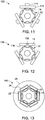
- one approach which is illustrated in FIG. 2 , is to increase saturation by the racetrack coils 22 to reduce and move the peak magnetic field produced by the racetrack coils 22 from an end winding section 32 of the coils 22 to a long section 34 of the coils 22, the sections being more clearly illustrated in the inset of FIG. 1 .
- Other approaches may include shaping the cryostat 24 so as to bring the racetrack coils 22 in closer proximity with the rotor 12, modifying the placement of or removing the yoke 28 to improve the magnetic field circuit, using multiple superconducting materials for the coils 22, or any combination thereof. Such embodiments are described in further detail with respect to FIGS. 3-18 below.
- FIG. 2 is a diagrammatic illustration of one of the racetrack coils 22 having a non-conductive end spacer 40 disposed between an outer coil 42 and an inner coil 44 of the windings of the coils 22.
- the outer coil 42 is disposed about the inner coil 44, and the superconducting magnet materials that form each of the coils may be the same, or may be different, as will be discussed in detail below.
- the outer coil 42 and the inner coil 44 include the same superconducting magnet material.
- first and second magnetic fields When a current is passed through the inner coil 44 and/or the outer coil 42, respective first and second magnetic fields may be produced.
- one of the coils may have a higher critical current than the other.
- the coil having the higher critical current may produce a stronger magnetic field.
- the peak magnetic field produced by such a racetrack coil 22 may be approximately 90%, 88%, or 85% lower than the peak magnetic field of the racetrack coils of FIG. 1 with no end spacer.
- the peak field may be reduced from approximately 8.8 Tesla (T) to approximately 7.7 T.
- T 8.8 Tesla
- magnetic flux is produced by a greater area of the coils 22, which may provide a greater area of saturation to magnetize the permanent magnets 14.
- FIG. 3 depicts a cryostat 50 having a flat surface 52 that is configured to be placed against the yoke 28 or other supporting structure.
- the cryostat 50 also includes a curved surface 54, which may be configured to allow the coils 22 inside the cryostat 50 to be disposed radially around the circumference of the rotor 12.
- FIG. 4 depicts the arrangement of the coils 22, which may have constant perimeter end windings, or other winding configurations which fit closely on a cylindrical surface, so as to allow more penetration of the magnetic field into the permanent magnets 14.
- An assembly 60 having the superconducting magnetizer assembly 18, the rotor 12, and the curved cryostat 50 is depicted in FIG. 5 .
- the cryostat 50 is placed against the circumferential bounds of the rotor 12 so as to allow the coils 22 to be disposed in a close-spaced relationship.
- the cryostat 50 allows the yoke 28 to be constructed from a single piece having the annular opening 20 configured to receive the rotor 12.
- FIG. 6 An embodiment of a similar approach is depicted in FIG. 6 , which illustrates a dished cryostat 70 having flat surfaces 72 bounding either side of a recess 74 within the cryostat 70.
- the recess 74 may be considered a dish that is formed so as to receive a portion of the rotor 12 therein.
- FIG. 7 The placement of the coils 22 in the dished cryostat 70 is illustrated in FIG. 7 , which shows the long section of the coil 22 as being at least as long as the length of the recess 74.
- the width of the end section 32 of the coil 22 is at least as large as the width of the recess 74.
- Such spatial relationships may allow effective magnetic field penetration into the permanent magnets 14 by the coils 22 in combination with the approach described with respect to FIG. 2 .
- FIG. 8 depicts an embodiment of an assembly 80 using the dished cryostat 70.
- each of the cryostats 70 has the flat surfaces 72 extending over the rotor 12, which is disposed within the respective recesses 74 of each of the cryostats 70.
- the assembly 80 includes a yoke 82 formed from a plurality of sections 84.
- Each section 84 is configured to receive one cryostat 70 each, although in other embodiments each section 84 may include more than one cryostat 70.
- the yoke 82 of the assembly 80 may require such sections 84 due to the manner in which each of the cryostats 70 interface with the rotor 12. For example, each of the sections 84 may be removed and replaced in the directions depicted by arrows 86.
- FIGS. 9-12 depict embodiments where the yoke is retained, and FIGS. 11 and 12 depict embodiments where the yoke is not present. Again, in some embodiments, certain magnetic materials may be replaced with others.
- FIG. 9 One such embodiment of an assembly 90 is depicted in FIG. 9 , which has the same geometric configuration as the assembly 10 of FIG. 1 .
- the assembly 10 has a yoke 92 that is constructed from permendur, which is an alloy of cobalt and iron.
- permendur which is an alloy of cobalt and iron.
- the magnetizing field normal to the surface of the coil packs 26 By replacing the iron yoke with the permedur yoke 92, the magnetizing field normal to the surface of the coil packs 26, the peak magnetic fields produced by the racetrack coils 22, and the operating margin is varied.
- the minimum magnetizing fields produced by the racetrack coils 22 may be increased, but the maximum magnetizing fields may be decreased. Peak magnetic field on the superconducting element may also be decreased, along with improving the operating margin of the superconductor.
- an assembly 110 includes a permendur yoke 112 having a thinner profile than the yokes of the embodiments described above. Additionally, the yoke 112 includes a series of block protrusions 114 that are disposed proximate the center of each of a set of widened coil packs 116116.
- the magnetizing field normal to the surface of the coil packs 116 and the peak magnetic fields produced by the racetrack coils 22 decrease compared to assembly 100, but the operating margin increases, for example by over 25% (e.g., from an operating margin of about 15% to an operating margin of about 19%), compared to assembly 100.
- FIGS. 11 and 12 illustrate embodiments wherein the yoke is not included in the assembly. It should be noted that when no external yoke is used, other features, such as a support stand or similar structure may be included so as to balance the radial forces produced by the superconducting magnets.
- FIG. 11 illustrates an assembly 120 having a similar configuration to that of the assembly 110 illustrated in FIG. 10 , but not having the thin profile yoke 112. However, it will be appreciated that the permendur blocks 114 are maintained within the assembly 120, for example using other support structures.
- the magnetizing field normal to the surface of the coil packs 116 and the peak magnetic fields produced by the racetrack coils 22 decrease compared to assembly 110, and the operating margin increases, for example by about 5% (e.g., from an operating margin of about 19% to an operating margin of about 20%), compared to assembly 110.
- FIG. 12 depicts an embodiment of an assembly 130 wherein the permendur blocks 114 of assembly 120 are removed, and a set of permendur blocks 132 are placed towards the end windings of the coil packs 116. Placing the permendur blocks 132 in such a location may reduce the peak magnetic field at the racetrack coils 22. Indeed, in the assembly 130, the magnetizing field normal to the surface of the coil packs 116 and the peak magnetic fields produced by the racetrack coils 22 decrease compared to assembly 120, with the operating margin remaining about the same as the assembly 120.
- While varying the geometry and/or magnetic materials present within the superconducting magnetizer assembly may have certain advantages, it may be desirable to increase the number of magnetizing poles within the magnetic circuit. For example, by increasing the number of magnetizing poles (i.e., increasing the number of coil packs), it may be possible to decrease the total number of operations required to magnetize a rotor. Further, in having a larger number of magnetizing features, the magnetization efficiency may increase. Such embodiments are illustrated diagrammatically in FIGS. 13-15 .
- FIG. 13 illustrates an assembly 140 having six coil packs 26, each having racetrack coils 22 (with end spacers 40) so as to generate six sets of magnetic fields, one for each of the six pairs of permanent magnets 14.
- the assembly 140 includes the iron yoke 28 to improve magnetization efficiency, reduce stray magnetic fields, and balance radial forces.
- the magnetizing field normal to the surface of the coil packs 26 and the peak magnetic fields produced by the racetrack coils 22 may be much higher compared to the assemblies described with respect to FIGS. 1 and 9-12 .
- operating margin decreases greatly, for example by over 400% (e.g., from an operating margin of about 13% to an operating margin of about 3%), compared to assembly 10.
- FIG. 14 illustrates an assembly 150 having a series of six coil packs 152 including the coils 22 and end spacers 40 for magnetizing each pole in one operation.
- the assembly 150 does not have an external yoke, but includes internal iron yokes 154 that are internal to the coil packs 152 so as to improve magnetization efficiency and reduce the peak fields at each coil 22.
- both the magnetizing field and the peak field decrease as compared to assembly 140, with operating margin increasing when compared to the same.
- FIG. 15 illustrates an embodiment of an assembly 160 having features similar to those of assemblies 140 and 150 of FIGS. 13 and 14 , respectively.
- assembly 160 includes the coil packs 152 having the internal iron yoke 154 so as to control peak field and improve magnetization efficiency.
- the assembly 160 includes the external iron yoke 28, which may balance radial forces as well as further reduce peak fields and improve magnetization efficiency. Indeed, when compared to assembly 150, assembly 160 has increased magnetization efficiency, reduced peak field, and increased operating margin.
- FIGS. 16-18 illustrate embodiments wherein at least two different types of superconducting materials are incorporated into the magnetizing assembly.
- FIG. 16 illustrates an embodiment of an assembly 170 having Nb 3 Sn coil packs 172 having Nb 3 Sn racetrack coils 174 and end spacers 40 interleaved with Nb 3 Ti coil packs 176 having NbTi racetrack coils 178.
- each coil pack is illustrated as a cross-section. While the NbTi coils 178 do not perform any substantial magnetization of the permanent magnets 14 as the Nb 3 Sn coils 174 do, this efficiently minimizes the use of high field wind and react superconductors in the overall assembly, so that magnetic efficiencies and peak field reductions may be achieved similar to those exhibited by the embodiments illustrated in FIGS. 13-15 .
- two of the sets of Nb 3 Sn coils 174 may be disposed proximate one another, with the other four sets of coils being the Nb 3 Ti coils 178.
- the assembly 180 therefore has one main magnetizing circuit, which is formed by combining the two sets of Nb 3 Sn coils 174 in a single cryostat 182. Because the Nb 3 Sn coils 174 are disposed proximate one another, the main magnetizing circuit magnetizes two pairs of the permanent magnets 14 at once. Accordingly, three operations are required to magnetize all of the permanent magnets 14 in the embodiment depicted in FIG. 17 .
- the NbTi coils 178 may be combined into a single cryostat 184. Such an arrangement is generally configured to increase the inter coil pack distance to help offset inter coil pack forces.
- FIG. 18 illustrates an assembly 190 having a main magnetization cryostat 192, and four separate NbTi coil packs 176 each having NbTi coils 178.
- the main magnetization cryostat 192 houses two hybrid coil sets 194 having both Nb 3 Sn coils and NbTi coils.
- the Nb 3 Sn coils are employed in the inner, high field section 198 and the NbTi are employed in the outer, lower field section 200.
- the Nb 3 Sn coils are stepped in to allow more volume for force containment resulting from coil interactions.
- the non-conductive end spacer 40 may be used to further reduce peak fields.
- Various technical effects of certain aspects of the invention may include lower running costs of the superconducting system, a smaller footprint than conventional magnetizers, and the ability to be deployed without the requirement of special facilities for operation (due to the lower power requirements).
- the present embodiments can lead to higher magnetization throughput than a conventional system.
- the embodiments describe herein may be modular, such as by using the separate coil packs described above, which allows components to be replaced as needed. Additionally, a greater percentage of magnetization of permanent magnets may allow more robust and longer lifetime magnetically-driven equipment, such as turbines, brakes, bearings, and so forth.
Landscapes
- Engineering & Computer Science (AREA)
- Power Engineering (AREA)
- Manufacturing & Machinery (AREA)
- Superconductive Dynamoelectric Machines (AREA)
- Magnetic Resonance Imaging Apparatus (AREA)
- Measuring Magnetic Variables (AREA)
- Permanent Field Magnets Of Synchronous Machinery (AREA)
Abstract
Description
- The subject matter disclosed herein relates generally to the magnetization of permanent magnets, and more specifically, to the magnetization of magnets disposed within cylindrical structures using one or more superconducting materials.
- Many electrical machines include one or more electric motors. Such electric motors typically include a rotor having permanent magnets disposed within the bulk of the rotor. During rotation, the rotor, having the permanent magnets, produces a rotating magnetic field that interacts with a stator. This electromagnetic interaction results in the conversion of electromagnetic energy into mechanical motion that drives the machine.
- Two approaches are typically used for the assembly of rotors having permanent magnets. In one approach, shaped materials are magnetized to generate the permanent magnets before they are disposed within the bulk of the rotor. This approach may present several drawbacks. For instance, fully magnetized permanent magnet pieces can be subject to electromagnetic interaction with any surrounding objects, such as other adjacent or proximate magnets, which in turn adds to the complexity of their handling procedures and insertion into the rotor. In a second approach, the shaped materials are first disposed within the rotor and a magnetizer is used to magnetize the permanent magnets. Such an approach is typically referred to as an in-situ magnetization process.
- The second approach can also present several drawbacks. To name a few, the energy and fabrication costs for conventional resistive magnetizers capable of generating a sufficient magnetic field flux for the magnetization process can be prohibitive. For example, some in-situ magnetizers are able to produce small magnetic fields sufficient only to magnetize small permanent magnets made of certain materials or grades (e.g., alnico and ferrite) that have low intrinsic coercivity (i.e., materials that can be easily demagnetized). However, many emerging applications for permanent magnet electric machines, such as wind turbine applications, or traction (e.g., magnetic bearing and braking) applications, would benefit from the use of high-coercivity rare-earth permanent magnet materials, which can often require strong magnetic fields. Moreover, as the permanent magnets increase in size, their magnetization becomes increasingly difficult due to inadequate field penetration produced by typical magnetizers. It should therefore be appreciated that due to physical constraints in addition to economic considerations, the in-situ magnetization of such materials is typically very difficult to deliver with conventional restive systems. Accordingly, it is now recognized that a need exists for a magnetizer capable of magnetizing rare-earth, high-coercivity materials in an efficient manner.
- The present embodiments are generally directed towards such magnetization. In one embodiment, a superconducting magnetizer assembly is provided. The assembly includes a coil pack having an inner coil including a first superconducting magnet material, the coil being configured to generate a first magnetic field in response to an electric current supplied to the coil, and an outer coil including a second superconducting magnet material, the outer coil being disposed about the inner coil and being configured to generate a second magnetic field in response to an electric current supplied to the outer coil. The coil pack also includes a container configured to house the inner and the outer coils.
- In another embodiment, a cryogenic container configured for use with a magnetizer assembly is provided. The container includes a chamber configured to house a superconducting magnet coil wound into a racetrack shape and to maintain the coil at a set temperature, and a curved outer surface enclosing the chamber and configured to radially interface with the surface of an annular member having one or more materials susceptible to magnetization.
- In a further embodiment, a coil pack configured for use with a magnetizer assembly is provided. The coil pack includes an inner coil having a first superconducting magnet material, the coil being configured to generate a first magnetic field in response to an electric current supplied to the coil. The pack also includes an outer coil having a second superconducting magnet material, the outer coil being disposed about the first coil and being configured to generate a second magnetic field in response to an electric current supplied to the second coil. Further, the pack includes a cryogenic container configured to house the inner and the outer coils and maintain the inner and the outer coil at a set temperature.
- Various features, aspects, and advantages of the present invention will become better understood when the following detailed description is read with reference to the accompanying drawings in which like characters represent like parts throughout the drawings, wherein:
-
FIG. 1 is an embodiment of an assembly having a superconducting magnetizer assembly and a rotor disposed within the magnetizer assembly, the magnetizer assembly including a plurality of superconducting coils configured to magnetize permanent magnet blocks within the rotor; -
FIG. 2 is an embodiment of a coil configuration for the superconducting coils ofFIG. 1 , the coil configuration including a non-conductive end spacer configured to reduce the peak field at the coil; -
FIG. 3 is a perspective illustration of an embodiment of a curved cryostat configured to house superconducting coils, and the curved cryostat allows the coils to interface with an annular rotor so as to facilitate magnetization of permanent magnets within the rotor; -
FIG. 4 is a schematic illustration of the cryostat ofFIG. 3 ; -
FIG. 5 is an end-on illustration of an assembly including a superconducting magnetizer assembly and a rotor disposed within the assembly, the superconducting magnetizer assembly utilizing the curved cryostat ofFIGS. 3 and 4 ; -
FIG. 6 is a perspective illustration of an embodiment of a dished cryostat configured to house superconducting coils, and the dished cryostat allows the coils to interface with an annular rotor so as to facilitate magnetization of permanent magnets within the rotor; -
FIG. 7 is a schematic illustration of the cryostat ofFIG. 6 ; -
FIG. 8 is an end-on illustration of an embodiment of an assembly including a superconducting magnetizer assembly and a rotor disposed within the assembly, the superconducting magnetizer assembly utilizing the dished cryostat ofFIGS. 6 and 7 ; -
FIG. 9 is an end-on illustration of an embodiment of an assembly including a superconducting magnetizer assembly and a rotor disposed within the assembly, the superconducting magnetizer assembly utilizing an external yoke configured to enhance the field alignment within the permanent magnet material, and the superconducting magnetizer assembly is arranged to allow the magnetization of 3 poles in one operation; -
FIG. 10 is an end-on illustration of an embodiment of an assembly including a superconducting magnetizer assembly and a rotor disposed within the assembly, the superconducting magnetizer assembly utilizing a thin-profile external yoke, widened coil packs, and yoke blocks interfacing with the coil packs; -
FIG. 11 is an end-on illustration of an embodiment of an assembly including a superconducting magnetizer assembly and a rotor disposed within the assembly, the superconducting magnetizer assembly not having an external yoke but having widened coil packs, and yoke blocks interfacing with the coil packs; -
FIG. 12 is an end-on illustration of an embodiment of an assembly including a superconducting magnetizer assembly and a rotor disposed within the assembly, the superconducting magnetizer assembly not having an external yoke but having widened coil packs and an internal yoke for interfacing with the coil packs; -
FIG. 13 is an end-on illustration of an embodiment of an assembly including a superconducting magnetizer assembly and a rotor disposed within the assembly, the superconducting magnetizer assembly having a number of superconducting magnets sufficient to magnetize all of the poles of a rotor in one operation; -
FIG. 14 is an end-on illustration of an embodiment of an assembly including a superconducting magnetizer assembly and a rotor disposed within the assembly, the superconducting magnetizer assembly having a number of superconducting magnets interfacing with internal yokes, the superconducting magnets being sufficient to magnetize all of the poles of a rotor in one operation, but without the use of an external return yoke; -
FIG. 15 is an end-on illustration of an embodiment of an assembly including a superconducting magnetizer assembly and a rotor disposed within the assembly, the superconducting magnetizer assembly having a number of superconducting magnets interfacing with internal yokes and being enclosed by an external yoke, the superconducting magnets being sufficient to magnetize all of the poles of a rotor in one operation; -
FIG. 16 is an end-on illustration of an embodiment of an assembly including a superconducting magnetizer assembly and a rotor disposed within the assembly, the superconducting magnetizer assembly having a combination of at least two different superconducting materials in the form of interleaving coil packs capable of magnetizing 3 poles in a single operation; -
FIG. 17 is an end-on illustration of an embodiment of an assembly including a superconducting magnetizer assembly and a rotor disposed within the assembly, the superconducting magnetizer assembly having a combination of at least two different superconducting materials, one of the superconducting materials being configured to act as a main magnetization circuit to magnetize each pole in the rotor individually; -
FIG. 18 is an end-on illustration of an embodiment of an assembly including a superconducting magnetizer assembly and a rotor disposed within the assembly, the superconducting magnetizer assembly having hybrid coil packs forming a main magnetization circuit and including one of the superconducting materials being disposed on an inner, high field portion of the coil pack and the other superconducting material being disposed on an outer, low field portion of the coil pack. - The present disclosure is generally directed towards improved systems and methods for the magnetization of materials disposed within a bulk material, such as the magnetization of as-formed permanent magnets disposed within an electric motor rotor. In accordance with the disclosed embodiments, one or more superconducting materials may be utilized to perform the in-situ magnetization of the as-formed permanent magnets. Moreover, the superconducting materials may be disposed in specially configured packs so as to facilitate the magnetization of the as-formed permanent magnets in a non-cubic shaped matrix, such as within the cylindrical rotor described above. Moreover, embodiments of magnetizer assemblies having features for controlling the magnetic fields generated by the superconducting materials are disclosed. Accordingly, to facilitate discussion of the present approaches towards such improved embodiments,
FIG. 1 illustrates anassembly 10 including arotor 12 having as-formed permanent magnets 14 (e.g., rare-earth magnets such as neodymium magnets) disposed within a bulk 16 (e.g., laminations) of therotor 12. In one embodiment, thepermanent magnets 14 may be NdFeB magnets. Therotor 12 is disposed inside of asuperconducting magnetizer assembly 18 having anannular opening 20 configured to receive therotor 12. In some embodiments, thesuperconducting magnetizer assembly 18 may support at least a portion of the weight of therotor 12 as the magnetization process is performed. - In a general sense, the
superconducting magnetizer assembly 18 includes a set ofsuperconducting coils 22 wound in a racetrack-like manner. Such a configuration, as referred to herein, may beracetrack coils 22. Theracetrack coils 22, as noted above, may incorporate a number of superconducting materials, for example niobium-3 tin (Nb3Sn), niobium-titanium (NbTi), MgB2 magnesium diboride, vanadium gallium (V3Ga), YBCo, or combinations thereof in one or more coils such as an inner coil and an outer coil, as will be discussed in further detail below. In the illustrated embodiment, and in the embodiments described below with respect toFIGS. 2-15 , thecoils 22 are NbTi coils. However, it should be noted that the superconductor material or materials chosen may be application specific and may contain a High Temperature Superconducting or Low Temperature Superconducting material, or both. Generally, theracetrack coils 22 produce a magnetic field when a current is passed through the coils. In some embodiments, the materials mentioned above that form theracetrack coils 22 exhibit decreased resistance when cooled. Accordingly, in such embodiments theracetrack coils 22 may be cooled so as to produce maximum magnetic flux. - Using cooling agents such as liquid helium, it may be possible to approach absolute zero in temperature (i.e., 0 Kelvin (K)), for example, below about 40 K. In one embodiment, liquid helium, which has a temperature of approximately 4 K, may be used as the active coolant to maintain the temperature of the
racetrack coils 22 at the temperature of the liquid helium. It will therefore be appreciated that each of the racetrack coils 22 may be disposed in acryostat 24, which may include other features such as thermal transfer agents (e.g., thermally conductive rods, heat pipes, thermal buses). Together, the racetrack coils 22 and thecryostats 24 each form coil packs 26. - Because the racetrack coils 22 are formed from superconducting materials, such as NbTi and/or Nb3Sn, which are capable of handling very high current densities, thermal dissipation may be reduced compared to conventional resistive magnetizers. That is, in conventional resistive magnetizers, the system must be pulsed to attain the required field levels for short periods of time. For instance, magnetizers incorporating superconducting coils may be energized and de-energized at much slower speeds, such as at ramp rates of -1 Tesla per minute, compared to conventional magnetizers incorporating conventional resistive coils, which need to be energized and de-energized at ramp rates of ∼1 Tesla per second. It should be noted that such ramp rates may be achieved with power supplies much smaller than those required for conventional magnetizers.
- In the illustrated embodiment of
FIG. 1 , the superconducting magnetizer assembly also includes ayoke 28, which may be made from iron, permendur, or similar materials, or any combination thereof. Theyoke 28 is generally configured to improve efficiency of the magnetization process by reducing fringe magnetic fields and balancing radial forces produced by thecoils 22. In the illustrated embodiment, theyoke 28 includes a plurality ofopenings 30 configured to house each of the coil packs 26. In this embodiment therotor 12 includes six pairs ofpermanent magnets 14 or "poles," and the superconducting magnetizer assembly includes three coil packs 26 each configured to magnetize a pair ofpermanent magnets 14. Therefore, in the depicted embodiment, at least two operations must be performed so as to magnetize therotor 12. For example, an embodiment of such a process may include energizing the racetrack coils 22 so as to magnetize thepermanent magnets 14 adjacent to their respective coil packs 26, followed by a clockwise or counter-clockwise rotation of therotor 12 so as to bring non-magnetized permanent magnet pairs in proximity to the coil packs 26, which allows magnetization of the remainingpermanent magnets 14. - While the racetrack coils 22 in accordance with
FIG. 1 may be generally applicable to the magnetization of rotors, it should be noted that as the size of therotor 12 increases, the required volume of the magnetic field produced by each of the racetrack coils 22 must also increase so as to provide sufficient magnetization of thepermanent magnets 14. However, as noted above, it can be very difficult for conventional resistive magnetizers to produce such fields. - For example, in embodiments where the diameter of the
rotor 12 is on the order of 0.1 m and above, the racetrack coils 22, in a simple wound configuration, may not be sufficient to provide sufficient magnetic field saturation of thepermanent magnets 14. Accordingly, it may be desirable to manipulate the magnetic field produced by thecoils 22 to as to provide more efficient magnetization. In accordance with the present disclosure, one approach, which is illustrated inFIG. 2 , is to increase saturation by the racetrack coils 22 to reduce and move the peak magnetic field produced by the racetrack coils 22 from anend winding section 32 of thecoils 22 to along section 34 of thecoils 22, the sections being more clearly illustrated in the inset ofFIG. 1 . Other approaches may include shaping thecryostat 24 so as to bring the racetrack coils 22 in closer proximity with therotor 12, modifying the placement of or removing theyoke 28 to improve the magnetic field circuit, using multiple superconducting materials for thecoils 22, or any combination thereof. Such embodiments are described in further detail with respect toFIGS. 3-18 below. - Therefore, keeping in mind the general characteristics of the
assembly 10 ofFIG. 1 , an embodiment of the approach of moving the peak field produced by thecoils 22 is illustrated inFIG. 2 . Specifically,FIG. 2 is a diagrammatic illustration of one of the racetrack coils 22 having anon-conductive end spacer 40 disposed between anouter coil 42 and aninner coil 44 of the windings of thecoils 22. Generally, theouter coil 42 is disposed about theinner coil 44, and the superconducting magnet materials that form each of the coils may be the same, or may be different, as will be discussed in detail below. In the illustrated embodiment, theouter coil 42 and theinner coil 44 include the same superconducting magnet material. When a current is passed through theinner coil 44 and/or theouter coil 42, respective first and second magnetic fields may be produced. In some embodiments, one of the coils may have a higher critical current than the other. In such embodiments, the coil having the higher critical current may produce a stronger magnetic field. Such embodiments are discussed below. It should be noted that the peak magnetic field produced by such aracetrack coil 22 may be approximately 90%, 88%, or 85% lower than the peak magnetic field of the racetrack coils ofFIG. 1 with no end spacer. For example, in an embodiment, the peak field may be reduced from approximately 8.8 Tesla (T) to approximately 7.7 T. Moreover, because the peak field is now moved to thelong portion 34 of thecoils 22, magnetic flux is produced by a greater area of thecoils 22, which may provide a greater area of saturation to magnetize thepermanent magnets 14. - Another approach to increasing magnetic efficiency, as noted above, is to shape the
cryostat 24 so as to allow thecoils 22 to be in closer proximity to therotor 12. Embodiments of such approaches are illustrated with respect toFIGS. 3-8 , and may be used in lieu of, or in combination with, the embodiment illustrated inFIG. 2 . Specifically,FIG. 3 depicts acryostat 50 having aflat surface 52 that is configured to be placed against theyoke 28 or other supporting structure. Thecryostat 50 also includes acurved surface 54, which may be configured to allow thecoils 22 inside thecryostat 50 to be disposed radially around the circumference of therotor 12. -
FIG. 4 depicts the arrangement of thecoils 22, which may have constant perimeter end windings, or other winding configurations which fit closely on a cylindrical surface, so as to allow more penetration of the magnetic field into thepermanent magnets 14. Anassembly 60 having thesuperconducting magnetizer assembly 18, therotor 12, and thecurved cryostat 50 is depicted inFIG. 5 . As may be appreciated, thecryostat 50 is placed against the circumferential bounds of therotor 12 so as to allow thecoils 22 to be disposed in a close-spaced relationship. It should be noted that in the embodiment depicted inFIGS. 3-5 , thecryostat 50 allows theyoke 28 to be constructed from a single piece having theannular opening 20 configured to receive therotor 12. - An embodiment of a similar approach is depicted in
FIG. 6 , which illustrates a dishedcryostat 70 havingflat surfaces 72 bounding either side of arecess 74 within thecryostat 70. Therecess 74 may be considered a dish that is formed so as to receive a portion of therotor 12 therein. The placement of thecoils 22 in the dishedcryostat 70 is illustrated inFIG. 7 , which shows the long section of thecoil 22 as being at least as long as the length of therecess 74. Moreover, the width of theend section 32 of thecoil 22 is at least as large as the width of therecess 74. Such spatial relationships may allow effective magnetic field penetration into thepermanent magnets 14 by thecoils 22 in combination with the approach described with respect toFIG. 2 . -
FIG. 8 depicts an embodiment of anassembly 80 using the dishedcryostat 70. As illustrated, when placed over therotor 12, each of thecryostats 70 has theflat surfaces 72 extending over therotor 12, which is disposed within therespective recesses 74 of each of thecryostats 70. In the illustrated embodiment, theassembly 80 includes a yoke 82 formed from a plurality ofsections 84. Eachsection 84 is configured to receive onecryostat 70 each, although in other embodiments eachsection 84 may include more than onecryostat 70. The yoke 82 of theassembly 80 may requiresuch sections 84 due to the manner in which each of thecryostats 70 interface with therotor 12. For example, each of thesections 84 may be removed and replaced in the directions depicted byarrows 86. - As noted above, another approach to improving the efficiency of the magnetization of the
permanent magnets 14 is to vary the magnetic circuit by changing geometries, arrangements, and/or magnetic materials. Such embodiments are illustrated with respect toFIGS. 9-12 .FIGS. 9 and 10 depict embodiments where the yoke is retained, andFIGS. 11 and 12 depict embodiments where the yoke is not present. Again, in some embodiments, certain magnetic materials may be replaced with others. - One such embodiment of an
assembly 90 is depicted inFIG. 9 , which has the same geometric configuration as theassembly 10 ofFIG. 1 . In the embodiment ofFIG. 9 , theassembly 10 has ayoke 92 that is constructed from permendur, which is an alloy of cobalt and iron. By replacing the iron yoke with thepermedur yoke 92, the magnetizing field normal to the surface of the coil packs 26, the peak magnetic fields produced by the racetrack coils 22, and the operating margin is varied. As an example, the minimum magnetizing fields produced by the racetrack coils 22 may be increased, but the maximum magnetizing fields may be decreased. Peak magnetic field on the superconducting element may also be decreased, along with improving the operating margin of the superconductor. - In the embodiment illustrated in
FIG. 10 , anassembly 110 includes apermendur yoke 112 having a thinner profile than the yokes of the embodiments described above. Additionally, theyoke 112 includes a series ofblock protrusions 114 that are disposed proximate the center of each of a set of widened coil packs 116116. In theassembly 110, the magnetizing field normal to the surface of the coil packs 116 and the peak magnetic fields produced by the racetrack coils 22 decrease compared to assembly 100, but the operating margin increases, for example by over 25% (e.g., from an operating margin of about 15% to an operating margin of about 19%), compared to assembly 100. - As noted above,
FIGS. 11 and 12 illustrate embodiments wherein the yoke is not included in the assembly. It should be noted that when no external yoke is used, other features, such as a support stand or similar structure may be included so as to balance the radial forces produced by the superconducting magnets. Specifically,FIG. 11 illustrates anassembly 120 having a similar configuration to that of theassembly 110 illustrated inFIG. 10 , but not having thethin profile yoke 112. However, it will be appreciated that the permendur blocks 114 are maintained within theassembly 120, for example using other support structures. In theassembly 120, the magnetizing field normal to the surface of the coil packs 116 and the peak magnetic fields produced by the racetrack coils 22 decrease compared toassembly 110, and the operating margin increases, for example by about 5% (e.g., from an operating margin of about 19% to an operating margin of about 20%), compared toassembly 110. -
FIG. 12 depicts an embodiment of anassembly 130 wherein the permendur blocks 114 ofassembly 120 are removed, and a set of permendur blocks 132 are placed towards the end windings of the coil packs 116. Placing the permendur blocks 132 in such a location may reduce the peak magnetic field at the racetrack coils 22. Indeed, in theassembly 130, the magnetizing field normal to the surface of the coil packs 116 and the peak magnetic fields produced by the racetrack coils 22 decrease compared toassembly 120, with the operating margin remaining about the same as theassembly 120. - While varying the geometry and/or magnetic materials present within the superconducting magnetizer assembly may have certain advantages, it may be desirable to increase the number of magnetizing poles within the magnetic circuit. For example, by increasing the number of magnetizing poles (i.e., increasing the number of coil packs), it may be possible to decrease the total number of operations required to magnetize a rotor. Further, in having a larger number of magnetizing features, the magnetization efficiency may increase. Such embodiments are illustrated diagrammatically in
FIGS. 13-15 . - Specifically,
FIG. 13 illustrates anassembly 140 having six coil packs 26, each having racetrack coils 22 (with end spacers 40) so as to generate six sets of magnetic fields, one for each of the six pairs ofpermanent magnets 14. It will be appreciated that when magnetization is performed using theassembly 140 illustrated inFIG. 13 , that only one operation may be required to fully magnetize therotor 12. Additionally, as illustrated, theassembly 140 includes theiron yoke 28 to improve magnetization efficiency, reduce stray magnetic fields, and balance radial forces. In theassembly 140, the magnetizing field normal to the surface of the coil packs 26 and the peak magnetic fields produced by the racetrack coils 22 may be much higher compared to the assemblies described with respect toFIGS. 1 and9-12 . However, operating margin decreases greatly, for example by over 400% (e.g., from an operating margin of about 13% to an operating margin of about 3%), compared toassembly 10. -
FIG. 14 illustrates anassembly 150 having a series of sixcoil packs 152 including thecoils 22 andend spacers 40 for magnetizing each pole in one operation. Theassembly 150 does not have an external yoke, but includes internal iron yokes 154 that are internal to the coil packs 152 so as to improve magnetization efficiency and reduce the peak fields at eachcoil 22. For theassembly 150, both the magnetizing field and the peak field decrease as compared toassembly 140, with operating margin increasing when compared to the same. -
FIG. 15 illustrates an embodiment of anassembly 160 having features similar to those ofassemblies FIGS. 13 and14 , respectively. Specifically,assembly 160 includes the coil packs 152 having theinternal iron yoke 154 so as to control peak field and improve magnetization efficiency. Additionally, theassembly 160 includes theexternal iron yoke 28, which may balance radial forces as well as further reduce peak fields and improve magnetization efficiency. Indeed, when compared toassembly 150,assembly 160 has increased magnetization efficiency, reduced peak field, and increased operating margin. - It should be noted that the utilization of a high field wind and react (or react and wind) superconductor, for example Nb3Sn, in all of the coil packs may be prohibitive from a logistical and cost standpoint. For example, Nb3Sn coils require features to offset the forces resulting from the large electromagnetic interactions. Accordingly, it may be desirable to incorporate features into the embodiments described above so as to mitigate such concerns. One such approach is to incorporate other superconducting materials, such as niobium-titanium (Nb3Ti), vanadium gallium (V3Ga), and so forth, into the assemblies described herein. Accordingly,
FIGS. 16-18 illustrate embodiments wherein at least two different types of superconducting materials are incorporated into the magnetizing assembly. -
FIG. 16 illustrates an embodiment of anassembly 170 having Nb3Sn coil packs 172 having Nb3Sn racetrack coils 174 and endspacers 40 interleaved with Nb3Ti coil packs 176 having NbTi racetrack coils 178. It should be noted that in order to facilitate discussion, each coil pack is illustrated as a cross-section. While the NbTi coils 178 do not perform any substantial magnetization of thepermanent magnets 14 as the Nb3Sn coils 174 do, this efficiently minimizes the use of high field wind and react superconductors in the overall assembly, so that magnetic efficiencies and peak field reductions may be achieved similar to those exhibited by the embodiments illustrated inFIGS. 13-15 . However, rather than being able to magnetize all of the magnetic poles in one operation as withassemblies assembly 170, wherein three of the pairs ofpermanent magnets 14 are magnetized, followed by rotation and magnetization (i.e., reenergizing the coils). - In another embodiment, which is illustrated as
assembly 180 ofFIG. 17 , rather than interleaving the coils, two of the sets of Nb3Sn coils 174 may be disposed proximate one another, with the other four sets of coils being the Nb3Ti coils 178. Theassembly 180 therefore has one main magnetizing circuit, which is formed by combining the two sets of Nb3Sn coils 174 in asingle cryostat 182. Because the Nb3Sn coils 174 are disposed proximate one another, the main magnetizing circuit magnetizes two pairs of thepermanent magnets 14 at once. Accordingly, three operations are required to magnetize all of thepermanent magnets 14 in the embodiment depicted inFIG. 17 . In a similar manner to the Nb3Sn coils 174, the NbTi coils 178 may be combined into asingle cryostat 184. Such an arrangement is generally configured to increase the inter coil pack distance to help offset inter coil pack forces. - To further reduce the amount of Nb3Sn that is utilized, it may be possible to hybridize the coils, wherein a single coil pack includes both NbTi coils and Nb3Sn coils. Such an embodiment is illustrated with respect to
FIG. 18 . Specifically,FIG. 18 illustrates anassembly 190 having amain magnetization cryostat 192, and four separate NbTi coil packs 176 each having NbTi coils 178. Themain magnetization cryostat 192 houses two hybrid coil sets 194 having both Nb3Sn coils and NbTi coils. Specifically, as shown in the expansion, the Nb3Sn coils are employed in the inner,high field section 198 and the NbTi are employed in the outer,lower field section 200. Such an arrangement allows the Nb3Sn coils to have maximum proximity to the permanent magnets that are being magnetized, which allows for complete local magnetic saturation of two pairs of thepermanent magnets 14. In the illustrated embodiment, the Nb3Sn coils are stepped in to allow more volume for force containment resulting from coil interactions. Optionally, thenon-conductive end spacer 40 may be used to further reduce peak fields. - Various technical effects of certain aspects of the invention may include lower running costs of the superconducting system, a smaller footprint than conventional magnetizers, and the ability to be deployed without the requirement of special facilities for operation (due to the lower power requirements). Moreover, the present embodiments can lead to higher magnetization throughput than a conventional system. The embodiments describe herein may be modular, such as by using the separate coil packs described above, which allows components to be replaced as needed. Additionally, a greater percentage of magnetization of permanent magnets may allow more robust and longer lifetime magnetically-driven equipment, such as turbines, brakes, bearings, and so forth.
- This written description uses examples to disclose the invention, including the preferred mode, and also to enable any person skilled in the art to practice the invention, including making and using any devices or systems and performing any incorporated methods. It should also be understood that the various examples disclosed herein may have features that can be combined with those of other examples or embodiments disclosed herein. That is, the present examples are presented in such as way as to simplify explanation but may also be combined one with another. The patentable scope of the invention is defmed by the claims, and may include other examples that occur to those skilled in the art. Such other examples are intended to be within the scope of the claims if they have structural elements that do not differ from the literal language of the claims, or if they include equivalent structural elements with insubstantial differences from the literal languages of the claims.
- Various aspects and embodiments of the present invention are defined by the following numbered clauses:
- 1. A superconducting magnetizer assembly, comprising:
- a coil pack, comprising:
- an inner coil comprising a first superconducting magnet material, the coil being configured to generate a first magnetic field in response to an electric current supplied to the coil;
- an outer coil comprising a second superconducting magnet material, the outer coil being disposed about the inner coil and being configured to generate a second magnetic field in response to an electric current supplied to the outer coil; and
- a container configured to house the inner and the outer coils.
- a coil pack, comprising:
- 2. The assembly of clause 1, comprising a yoke disposed proximate the coil pack being configured to constrain the first and second magnetic fields to reduce the strength of the first field at an end winding of the inner coil.
- 3. The assembly of any preceding clause, wherein the yoke is disposed within the coil pack.
- 4. The assembly of any preceding clause, wherein the yoke comprises iron or permendur.
- 5. The assembly of any preceding clause, wherein the yoke comprises an annular ring configured to at least partially envelop the coil pack.
- 6. The assembly of any preceding clause, wherein the first superconducting magnet material and the second superconducting magnet material are the same.
- 7. The assembly of any preceding clause, wherein the first superconducting magnet material is different from the second superconducting magnet material, and the first superconducting magnet material has a higher critical current where the magnetic field is stronger than the second superconducting magnet material.
- 8. The assembly of any preceding clause, wherein the container is a cryogenic container configured to maintain the inner and the outer coils at a set temperature.
- 9. The assembly of any preceding clause, wherein the container is curved so as to radially interface substantially continuously throughout the length of the container with the surface of an annular rotor.
- 10. The assembly of any preceding clause, wherein the container comprises a curved recess bounded by flat surfaces, the curved recess being configured to radially interface with the surface of an annular rotor.
- 11. The assembly of any preceding clause, comprising additional coil packs having respective coils with superconducting magnet materials, the coils being configured to generate respective magnetic fields in response to an electrical current applied to the additional coils.
- 12. The assembly of any preceding clause, comprising an annular shaped yoke configured to receive the coil pack and the additional coil packs, the coil packs being disposed radially about an inner circumference of the yoke and forming an annular opening configured to receive a cylindrical rotor having one or more permanent magnets, and the coils of the coil packs are configured to provide approximately 100% saturation of the permanent magnets with a magnetization field formed by the first and second magnetic fields generated by each of the coils.
- 13. The assembly of any preceding clause, wherein the assembly is configured to magnetize all of the permanent magnets within the rotor in one, two, or three operations.
- 14. The assembly of any preceding clause, wherein the respective superconducting magnet materials of at least one of the additional coil packs is different than the first or the second superconducting magnet material.
- 15. The assembly of any preceding clause, wherein the coil pack comprises a non-conductive end spacer disposed between an end winding of the inner coil and an end winding of the outer coil.
- 16. A cryogenic container configured for use with a magnetizer assembly, comprising:
- a chamber configured to house a superconducting magnet coil wound into a racetrack shape and to maintain the coil at a set temperature; and
- a curved outer surface enclosing the chamber and configured to radially interface with the surface of an annular member having one or more materials susceptible to magnetization.
- 17. The cryogenic container of any preceding clause, wherein the curved outer surface is bounded by flat surfaces to form a dished surface configured to partially enclose the annular member.
- 18. The cryogenic container of any preceding clause, wherein the curved outer surface runs the entire length of the container.
- 19. A coil pack configured for use with a magnetizer assembly, comprising:
- an inner coil comprising a first superconducting magnet material, the coil being configured to generate a first magnetic field in response to an electric current supplied to the coil;
- an outer coil comprising a second superconducting magnet material, the outer coil being disposed about the first coil and being configured to generate a second magnetic field in response to an electric current supplied to the second coil; and
- a cryogenic container configured to house the inner and the outer coils and maintain the inner and the outer coil at a set temperature.
- 20. The assembly of any preceding clause, wherein the first superconducting magnet material is different from the second superconducting magnet material and the first magnetic field is stronger than the second magnetic field.
Claims (15)
- A superconducting magnetizer assembly (18), comprising:a coil pack, comprising:an inner coil (44) comprising a first superconducting magnet material, the coil being configured to generate a first magnetic field in response to an electric current supplied to the coil;an outer coil (42) comprising a second superconducting magnet material, the outer coil (42) being disposed about the inner coil (44) and being configured to generate a second magnetic field in response to an electric current supplied to the outer coil (42); anda container configured to house the inner and the outer coils (42, 44).
- The assembly (18) of claim 1, comprising a yoke (28) disposed proximate the coil pack being configured to constrain the first and second magnetic fields to reduce the strength of the first field at an end winding (32) of the inner coil (44).
- The assembly (18) of claim 2, wherein the yoke (28) is disposed within the coil pack.
- The assembly (18) of claim 2 or claim 3, wherein the yoke (28) comprises iron or permendur.
- The assembly (18) of any of claims 2 to 4, wherein the yoke (28) comprises an annular ring configured to at least partially envelop the coil pack.
- The assembly of any preceding claim, wherein the first superconducting magnet material and the second superconducting magnet material are the same.
- The assembly (18) of any preceding claim, wherein the first superconducting magnet material is different from the second superconducting magnet material, and the first superconducting magnet material has a higher critical current where the magnetic field is stronger than the second superconducting magnet material.
- The assembly (18) of any preceding claim, wherein the container is a cryogenic container configured to maintain the inner and the outer coils (42, 44) at a set temperature, and the container is curved so as to radially interface with the surface of an annular rotor (12), wherein the curved surface (54) runs at least partially along the length of the container.
- The assembly (18) of any preceding claim, comprising additional coil packs (26) having respective coils with superconducting magnet materials, the coils being configured to generate respective magnetic fields in response to an electrical current applied to the additional coils.
- The assembly (18) of claim 9, comprising an annular shaped yoke (28) configured to receive the coil pack and the additional coil packs (26), the coil packs (26) being disposed radially about an inner circumference of the yoke (28) and forming an annular opening (20) configured to receive a cylindrical rotor (12) having one or more permanent magnets (14), and the coils of the coil packs (26) are configured to provide approximately 100% saturation of the permanent magnets (14) with a magnetization field formed by the first and second magnetic fields generated by each of the coils.
- The assembly (18) of claim 9 or claim 10, wherein the respective superconducting magnet materials of at least one of the additional coil packs (26) is different than the first or the second superconducting magnet material.
- The assembly (18) of any preceding claim, wherein the coil pack comprises a non-conductive end spacer (40) disposed between an end winding (32) of the inner coil (44) and an end winding (32) of the outer coil (42).
- A cryogenic container configured for use with a magnetizer assembly (18), comprising:a chamber configured to house a superconducting magnet coil wound into a racetrack shape and to maintain the coil at a set temperature; anda curved outer surface enclosing the chamber and configured to radially interface with the surface of an annular member having one or more materials susceptible to magnetization.
- The cryogenic container of claim 13, wherein the curved outer surface is bounded by flat surfaces (52) to form a dished surface configured to partially enclose the annular member.
- The cryogenic container of claim 13 or claim 14, wherein the curved outer surface runs the entire length of the container.
Applications Claiming Priority (1)
| Application Number | Priority Date | Filing Date | Title |
|---|---|---|---|
| US13/007,382 US8362863B2 (en) | 2011-01-14 | 2011-01-14 | System and method for magnetization of rare-earth permanent magnets |
Publications (3)
| Publication Number | Publication Date |
|---|---|
| EP2477198A2 true EP2477198A2 (en) | 2012-07-18 |
| EP2477198A3 EP2477198A3 (en) | 2017-07-05 |
| EP2477198B1 EP2477198B1 (en) | 2019-09-18 |
Family
ID=44559418
Family Applications (1)
| Application Number | Title | Priority Date | Filing Date |
|---|---|---|---|
| EP12151018.4A Active EP2477198B1 (en) | 2011-01-14 | 2012-01-13 | System and method for magnetization of rare-earth permanent magnets |
Country Status (4)
| Country | Link |
|---|---|
| US (2) | US8362863B2 (en) |
| EP (1) | EP2477198B1 (en) |
| CN (1) | CN102610360B (en) |
| IN (1) | IN2012DE00125A (en) |
Families Citing this family (14)
| Publication number | Priority date | Publication date | Assignee | Title |
|---|---|---|---|---|
| GR20090100276A (en) * | 2009-05-15 | 2010-12-21 | Αθανασιος Ανδρεας Νασικας | Magnetic propulsion with use of superconductors trapping magnetic fields |
| US9257219B2 (en) * | 2012-08-06 | 2016-02-09 | Correlated Magnetics Research, Llc. | System and method for magnetization |
| WO2012000503A2 (en) * | 2010-06-30 | 2012-01-05 | Vestas Wind Systems A/S | Apparatus and methods for magnetizing and demagnetizing magnetic poles in an electrical machine |
| US20130147582A1 (en) * | 2011-11-14 | 2013-06-13 | Nassikas A. Athanassios | Propulsion means using magnetic field trapping superconductors |
| US20130252819A1 (en) * | 2012-03-26 | 2013-09-26 | Yuriy ZAKUSKIN | Cryo-magnetic motor |
| JP6262564B2 (en) * | 2014-02-24 | 2018-01-17 | 中部電力株式会社 | Manufacturing method of superconducting deformed coil |
| KR101587839B1 (en) * | 2014-06-25 | 2016-01-22 | 주식회사 코아비스 | Polarizing device for a BLDC motor ring magnet |
| KR101913011B1 (en) * | 2016-12-19 | 2018-10-29 | 창원대학교 산학협력단 | Flexible support apparatus for superconducting magnet in superconducting rotating machine |
| WO2021138471A1 (en) * | 2019-12-31 | 2021-07-08 | Baker Hughes Oilfield Operations, Llc | Systems and methods for magnetizing permanent magnet rotors |
| EP3923305A1 (en) | 2020-06-10 | 2021-12-15 | General Electric Renovables España S.L. | Magnetizing permanent magnets |
| CN112530659B (en) * | 2020-11-30 | 2022-04-12 | 北京航空航天大学 | A simulation demagnetization current generating device for magnetism shielding section of thick bamboo demagnetization |
| JP2022110323A (en) * | 2021-01-18 | 2022-07-29 | 住友重機械工業株式会社 | Superconducting magnet device |
| CN113903543B (en) * | 2021-09-07 | 2022-06-21 | 华中科技大学 | Permanent magnet motor magnetizing device and method based on modular coil |
| JP2023144536A (en) * | 2022-03-28 | 2023-10-11 | 本田技研工業株式会社 | Magnetization method and magnetization device |
Family Cites Families (31)
| Publication number | Priority date | Publication date | Assignee | Title |
|---|---|---|---|---|
| DE1279182B (en) * | 1965-09-11 | 1968-10-03 | Siemens Ag | Superconducting coil |
| JPS5177524A (en) * | 1974-11-29 | 1976-07-05 | Gen Electric | Kobaruto kidoruigokin no jikahoho |
| JPS5912004B2 (en) * | 1976-07-05 | 1984-03-19 | 誠 桂井 | Quasi-superconducting coil |
| DE2907898A1 (en) * | 1979-03-01 | 1980-09-11 | Steingroever Erich Dr Ing | MULTIPOLE DEVICE AND METHOD FOR MAGNETIZING RING-SHAPED PERMANENT MAGNETS |
| JPS62210602A (en) * | 1986-03-11 | 1987-09-16 | Sumitomo Electric Ind Ltd | Superconductive magnet |
| JPH02178904A (en) * | 1988-12-29 | 1990-07-11 | Matsushita Electric Ind Co Ltd | Magnetizing device for high coercive force permanent magnet |
| US5204569A (en) * | 1990-02-07 | 1993-04-20 | Asmo Co., Ltd. | Anisotropic magnet for rotary electric machine |
| JP2896188B2 (en) * | 1990-03-27 | 1999-05-31 | 三菱電機株式会社 | Bending magnets for charged particle devices |
| US5113163A (en) * | 1990-11-13 | 1992-05-12 | The United States Of America As Represented By The Secretary Of The Army | Adjustable magnetic field superconducting solenoid |
| JPH04359406A (en) * | 1991-06-05 | 1992-12-11 | Toshiba Corp | Superconducting coil |
| JP3028039B2 (en) * | 1995-02-28 | 2000-04-04 | 株式会社日立製作所 | Hollow plate-shaped laminated conductor superconducting magnet |
| US6111490A (en) * | 1996-06-19 | 2000-08-29 | Aisin Seiki Kabushiki Kaisha | Superconducting magnet apparatus and method for magnetizing superconductor |
| US6621395B1 (en) * | 1997-02-18 | 2003-09-16 | Massachusetts Institute Of Technology | Methods of charging superconducting materials |
| US6693504B1 (en) * | 2000-01-11 | 2004-02-17 | American Superconductor Corporation | Internal support for superconductor windings |
| US6441521B1 (en) * | 2000-05-12 | 2002-08-27 | Reliance Electric Technologies, Llc | Hybrid superconducting motor/generator |
| DE10033411C2 (en) * | 2000-07-08 | 2002-08-14 | Bruker Biospin Gmbh | Actively shielded superconducting magnet with protective device |
| DE10049766A1 (en) * | 2000-09-29 | 2002-04-11 | Siemens Ag | Magnetizing magnet systems involves feeding direct current that is regulated continuously or in stages to coil made from high temperature superconductor to magnetize permanent magnets |
| US6885267B2 (en) * | 2003-03-17 | 2005-04-26 | Hitachi Metals Ltd. | Magnetic-field-generating apparatus and magnetic field orientation apparatus using it |
| KR20050007498A (en) * | 2003-07-08 | 2005-01-19 | 주식회사 덕성 | Superconducting magnet for generating horizontal magnetic field using bended circle or ellipse-shaped coils |
| EP1513168B1 (en) * | 2003-09-02 | 2017-03-08 | Albert Maurer | Method and apparatus for magnetising a magnet system |
| US7859374B2 (en) * | 2005-10-03 | 2010-12-28 | Massachusetts Institute Of Technology | Annular magnet system for magnetic resonance spectroscopy |
| US20070159281A1 (en) * | 2006-01-10 | 2007-07-12 | Liang Li | System and method for assembly of an electromagnetic machine |
| US7609139B2 (en) * | 2006-03-10 | 2009-10-27 | Florida State University Research Foundation | Split Florida-helix magnet |
| US20070242406A1 (en) * | 2006-04-17 | 2007-10-18 | Annis Theodore C | Electricity generating apparatus utilizing a single magnetic flux path |
| JP4890119B2 (en) * | 2006-06-23 | 2012-03-07 | 株式会社Ihi | Superconducting coil device and inductor type synchronous machine |
| US20090009012A1 (en) * | 2007-07-03 | 2009-01-08 | General Electric Company | Assembly and method for magnetization of permanent magnet rotors in electrical machines |
| EP2028750A2 (en) * | 2007-08-23 | 2009-02-25 | Zenergy Power GmbH | Winding form for winding a saddle coil |
| US8766753B2 (en) * | 2009-07-09 | 2014-07-01 | General Electric Company | In-situ magnetizer |
| US8258906B2 (en) * | 2009-08-12 | 2012-09-04 | General Electric Company | Superconducting magnetizer |
| US8710944B2 (en) | 2010-05-25 | 2014-04-29 | General Electric Company | Superconducting magnetizer |
| US8332004B2 (en) | 2010-12-23 | 2012-12-11 | General Electric Company | System and method for magnetization of rare-earth permanent magnets |
-
2011
- 2011-01-14 US US13/007,382 patent/US8362863B2/en active Active
-
2012
- 2012-01-13 EP EP12151018.4A patent/EP2477198B1/en active Active
- 2012-01-13 IN IN125DE2012 patent/IN2012DE00125A/en unknown
- 2012-01-14 CN CN201210067443.3A patent/CN102610360B/en active Active
- 2012-12-05 US US13/705,697 patent/US8471660B2/en not_active Expired - Fee Related
Non-Patent Citations (1)
| Title |
|---|
| None |
Also Published As
| Publication number | Publication date |
|---|---|
| US20110221552A1 (en) | 2011-09-15 |
| CN102610360A (en) | 2012-07-25 |
| CN102610360B (en) | 2016-09-07 |
| EP2477198B1 (en) | 2019-09-18 |
| IN2012DE00125A (en) | 2015-05-22 |
| US8362863B2 (en) | 2013-01-29 |
| US8471660B2 (en) | 2013-06-25 |
| EP2477198A3 (en) | 2017-07-05 |
| US20130093546A1 (en) | 2013-04-18 |
Similar Documents
| Publication | Publication Date | Title |
|---|---|---|
| US8471660B2 (en) | Assembly for magnetization of rare-earth permanent magnets | |
| CA2711363C (en) | Superconducting magnetizer | |
| US8354907B2 (en) | Superconducting coil assembly and magnetic field generating equipment | |
| EP0508936B1 (en) | Flux-trapped superconductive motor and method therefor | |
| US7492073B2 (en) | Superconducting rotating machines with stationary field coils | |
| JP5448296B2 (en) | Tubular electrical machine | |
| KR102181807B1 (en) | Superconductive electric motor and generator | |
| US6441521B1 (en) | Hybrid superconducting motor/generator | |
| CN102856032B (en) | A kind of installation method of Halbach structure permanent magnet | |
| CN108050156A (en) | A kind of sextupole hybrid magnetic bearing | |
| GB2462532A (en) | Brushless motor/generator with trapped-flux superconductors | |
| US9583997B2 (en) | Magnetizer and assembler for electrical machines | |
| US20160322881A1 (en) | Integrated motor generator flywheel with rotating permanent magnet | |
| JP3028039B2 (en) | Hollow plate-shaped laminated conductor superconducting magnet | |
| US20150229168A1 (en) | Superconducting field pole | |
| EP2487695B1 (en) | System and method for magnetization of rare-earth permanent magnets | |
| US7291958B2 (en) | Rotating back iron for synchronous motors/generators | |
| JP2011061994A (en) | Superconducting rotating machine | |
| JP6899022B1 (en) | Motor device | |
| Chubraeva et al. | Development of the Converter-Storage System Based on Smart Materials |
Legal Events
| Date | Code | Title | Description |
|---|---|---|---|
| PUAI | Public reference made under article 153(3) epc to a published international application that has entered the european phase |
Free format text: ORIGINAL CODE: 0009012 |
|
| AK | Designated contracting states |
Kind code of ref document: A2 Designated state(s): AL AT BE BG CH CY CZ DE DK EE ES FI FR GB GR HR HU IE IS IT LI LT LU LV MC MK MT NL NO PL PT RO RS SE SI SK SM TR |
|
| AX | Request for extension of the european patent |
Extension state: BA ME |
|
| RIC1 | Information provided on ipc code assigned before grant |
Ipc: H02K 15/03 20060101ALI20161219BHEP Ipc: H01F 13/00 20060101ALI20161219BHEP Ipc: H01F 6/06 20060101ALI20161219BHEP Ipc: H01F 6/04 20060101AFI20161219BHEP |
|
| PUAL | Search report despatched |
Free format text: ORIGINAL CODE: 0009013 |
|
| RIC1 | Information provided on ipc code assigned before grant |
Ipc: H01F 6/04 20060101AFI20170509BHEP Ipc: H02K 15/03 20060101ALI20170509BHEP Ipc: H01F 13/00 20060101ALI20170509BHEP Ipc: H01F 6/06 20060101ALI20170509BHEP |
|
| AK | Designated contracting states |
Kind code of ref document: A3 Designated state(s): AL AT BE BG CH CY CZ DE DK EE ES FI FR GB GR HR HU IE IS IT LI LT LU LV MC MK MT NL NO PL PT RO RS SE SI SK SM TR |
|
| AX | Request for extension of the european patent |
Extension state: BA ME |
|
| RIC1 | Information provided on ipc code assigned before grant |
Ipc: H01F 13/00 20060101ALI20170526BHEP Ipc: H01F 6/06 20060101ALI20170526BHEP Ipc: H01F 6/04 20060101AFI20170526BHEP Ipc: H02K 15/03 20060101ALI20170526BHEP |
|
| STAA | Information on the status of an ep patent application or granted ep patent |
Free format text: STATUS: REQUEST FOR EXAMINATION WAS MADE |
|
| 17P | Request for examination filed |
Effective date: 20180105 |
|
| RBV | Designated contracting states (corrected) |
Designated state(s): AL AT BE BG CH CY CZ DE DK EE ES FI FR GB GR HR HU IE IS IT LI LT LU LV MC MK MT NL NO PL PT RO RS SE SI SK SM TR |
|
| STAA | Information on the status of an ep patent application or granted ep patent |
Free format text: STATUS: EXAMINATION IS IN PROGRESS |
|
| 17Q | First examination report despatched |
Effective date: 20181031 |
|
| GRAP | Despatch of communication of intention to grant a patent |
Free format text: ORIGINAL CODE: EPIDOSNIGR1 |
|
| STAA | Information on the status of an ep patent application or granted ep patent |
Free format text: STATUS: GRANT OF PATENT IS INTENDED |
|
| INTG | Intention to grant announced |
Effective date: 20190509 |
|
| GRAS | Grant fee paid |
Free format text: ORIGINAL CODE: EPIDOSNIGR3 |
|
| GRAA | (expected) grant |
Free format text: ORIGINAL CODE: 0009210 |
|
| STAA | Information on the status of an ep patent application or granted ep patent |
Free format text: STATUS: THE PATENT HAS BEEN GRANTED |
|
| AK | Designated contracting states |
Kind code of ref document: B1 Designated state(s): AL AT BE BG CH CY CZ DE DK EE ES FI FR GB GR HR HU IE IS IT LI LT LU LV MC MK MT NL NO PL PT RO RS SE SI SK SM TR |
|
| REG | Reference to a national code |
Ref country code: GB Ref legal event code: FG4D |
|
| REG | Reference to a national code |
Ref country code: CH Ref legal event code: EP |
|
| REG | Reference to a national code |
Ref country code: AT Ref legal event code: REF Ref document number: 1182282 Country of ref document: AT Kind code of ref document: T Effective date: 20191015 |
|
| REG | Reference to a national code |
Ref country code: IE Ref legal event code: FG4D |
|
| REG | Reference to a national code |
Ref country code: DE Ref legal event code: R096 Ref document number: 602012064038 Country of ref document: DE |
|
| REG | Reference to a national code |
Ref country code: NL Ref legal event code: MP Effective date: 20190918 |
|
| PG25 | Lapsed in a contracting state [announced via postgrant information from national office to epo] |
Ref country code: LT Free format text: LAPSE BECAUSE OF FAILURE TO SUBMIT A TRANSLATION OF THE DESCRIPTION OR TO PAY THE FEE WITHIN THE PRESCRIBED TIME-LIMIT Effective date: 20190918 Ref country code: HR Free format text: LAPSE BECAUSE OF FAILURE TO SUBMIT A TRANSLATION OF THE DESCRIPTION OR TO PAY THE FEE WITHIN THE PRESCRIBED TIME-LIMIT Effective date: 20190918 Ref country code: BG Free format text: LAPSE BECAUSE OF FAILURE TO SUBMIT A TRANSLATION OF THE DESCRIPTION OR TO PAY THE FEE WITHIN THE PRESCRIBED TIME-LIMIT Effective date: 20191218 Ref country code: NO Free format text: LAPSE BECAUSE OF FAILURE TO SUBMIT A TRANSLATION OF THE DESCRIPTION OR TO PAY THE FEE WITHIN THE PRESCRIBED TIME-LIMIT Effective date: 20191218 Ref country code: SE Free format text: LAPSE BECAUSE OF FAILURE TO SUBMIT A TRANSLATION OF THE DESCRIPTION OR TO PAY THE FEE WITHIN THE PRESCRIBED TIME-LIMIT Effective date: 20190918 Ref country code: FI Free format text: LAPSE BECAUSE OF FAILURE TO SUBMIT A TRANSLATION OF THE DESCRIPTION OR TO PAY THE FEE WITHIN THE PRESCRIBED TIME-LIMIT Effective date: 20190918 |
|
| REG | Reference to a national code |
Ref country code: LT Ref legal event code: MG4D |
|
| PG25 | Lapsed in a contracting state [announced via postgrant information from national office to epo] |
Ref country code: RS Free format text: LAPSE BECAUSE OF FAILURE TO SUBMIT A TRANSLATION OF THE DESCRIPTION OR TO PAY THE FEE WITHIN THE PRESCRIBED TIME-LIMIT Effective date: 20190918 Ref country code: GR Free format text: LAPSE BECAUSE OF FAILURE TO SUBMIT A TRANSLATION OF THE DESCRIPTION OR TO PAY THE FEE WITHIN THE PRESCRIBED TIME-LIMIT Effective date: 20191219 Ref country code: AL Free format text: LAPSE BECAUSE OF FAILURE TO SUBMIT A TRANSLATION OF THE DESCRIPTION OR TO PAY THE FEE WITHIN THE PRESCRIBED TIME-LIMIT Effective date: 20190918 Ref country code: LV Free format text: LAPSE BECAUSE OF FAILURE TO SUBMIT A TRANSLATION OF THE DESCRIPTION OR TO PAY THE FEE WITHIN THE PRESCRIBED TIME-LIMIT Effective date: 20190918 |
|
| REG | Reference to a national code |
Ref country code: AT Ref legal event code: MK05 Ref document number: 1182282 Country of ref document: AT Kind code of ref document: T Effective date: 20190918 |
|
| PG25 | Lapsed in a contracting state [announced via postgrant information from national office to epo] |
Ref country code: PT Free format text: LAPSE BECAUSE OF FAILURE TO SUBMIT A TRANSLATION OF THE DESCRIPTION OR TO PAY THE FEE WITHIN THE PRESCRIBED TIME-LIMIT Effective date: 20200120 Ref country code: ES Free format text: LAPSE BECAUSE OF FAILURE TO SUBMIT A TRANSLATION OF THE DESCRIPTION OR TO PAY THE FEE WITHIN THE PRESCRIBED TIME-LIMIT Effective date: 20190918 Ref country code: NL Free format text: LAPSE BECAUSE OF FAILURE TO SUBMIT A TRANSLATION OF THE DESCRIPTION OR TO PAY THE FEE WITHIN THE PRESCRIBED TIME-LIMIT Effective date: 20190918 Ref country code: AT Free format text: LAPSE BECAUSE OF FAILURE TO SUBMIT A TRANSLATION OF THE DESCRIPTION OR TO PAY THE FEE WITHIN THE PRESCRIBED TIME-LIMIT Effective date: 20190918 Ref country code: EE Free format text: LAPSE BECAUSE OF FAILURE TO SUBMIT A TRANSLATION OF THE DESCRIPTION OR TO PAY THE FEE WITHIN THE PRESCRIBED TIME-LIMIT Effective date: 20190918 Ref country code: IT Free format text: LAPSE BECAUSE OF FAILURE TO SUBMIT A TRANSLATION OF THE DESCRIPTION OR TO PAY THE FEE WITHIN THE PRESCRIBED TIME-LIMIT Effective date: 20190918 Ref country code: RO Free format text: LAPSE BECAUSE OF FAILURE TO SUBMIT A TRANSLATION OF THE DESCRIPTION OR TO PAY THE FEE WITHIN THE PRESCRIBED TIME-LIMIT Effective date: 20190918 Ref country code: PL Free format text: LAPSE BECAUSE OF FAILURE TO SUBMIT A TRANSLATION OF THE DESCRIPTION OR TO PAY THE FEE WITHIN THE PRESCRIBED TIME-LIMIT Effective date: 20190918 |
|
| PG25 | Lapsed in a contracting state [announced via postgrant information from national office to epo] |
Ref country code: SM Free format text: LAPSE BECAUSE OF FAILURE TO SUBMIT A TRANSLATION OF THE DESCRIPTION OR TO PAY THE FEE WITHIN THE PRESCRIBED TIME-LIMIT Effective date: 20190918 Ref country code: IS Free format text: LAPSE BECAUSE OF FAILURE TO SUBMIT A TRANSLATION OF THE DESCRIPTION OR TO PAY THE FEE WITHIN THE PRESCRIBED TIME-LIMIT Effective date: 20200224 Ref country code: SK Free format text: LAPSE BECAUSE OF FAILURE TO SUBMIT A TRANSLATION OF THE DESCRIPTION OR TO PAY THE FEE WITHIN THE PRESCRIBED TIME-LIMIT Effective date: 20190918 Ref country code: CZ Free format text: LAPSE BECAUSE OF FAILURE TO SUBMIT A TRANSLATION OF THE DESCRIPTION OR TO PAY THE FEE WITHIN THE PRESCRIBED TIME-LIMIT Effective date: 20190918 |
|
| REG | Reference to a national code |
Ref country code: DE Ref legal event code: R097 Ref document number: 602012064038 Country of ref document: DE |
|
| PLBE | No opposition filed within time limit |
Free format text: ORIGINAL CODE: 0009261 |
|
| STAA | Information on the status of an ep patent application or granted ep patent |
Free format text: STATUS: NO OPPOSITION FILED WITHIN TIME LIMIT |
|
| PG2D | Information on lapse in contracting state deleted |
Ref country code: IS |
|
| PG25 | Lapsed in a contracting state [announced via postgrant information from national office to epo] |
Ref country code: DK Free format text: LAPSE BECAUSE OF FAILURE TO SUBMIT A TRANSLATION OF THE DESCRIPTION OR TO PAY THE FEE WITHIN THE PRESCRIBED TIME-LIMIT Effective date: 20190918 Ref country code: IS Free format text: LAPSE BECAUSE OF FAILURE TO SUBMIT A TRANSLATION OF THE DESCRIPTION OR TO PAY THE FEE WITHIN THE PRESCRIBED TIME-LIMIT Effective date: 20200119 |
|
| REG | Reference to a national code |
Ref country code: DE Ref legal event code: R119 Ref document number: 602012064038 Country of ref document: DE |
|
| 26N | No opposition filed |
Effective date: 20200619 |
|
| PG25 | Lapsed in a contracting state [announced via postgrant information from national office to epo] |
Ref country code: SI Free format text: LAPSE BECAUSE OF FAILURE TO SUBMIT A TRANSLATION OF THE DESCRIPTION OR TO PAY THE FEE WITHIN THE PRESCRIBED TIME-LIMIT Effective date: 20190918 Ref country code: MC Free format text: LAPSE BECAUSE OF FAILURE TO SUBMIT A TRANSLATION OF THE DESCRIPTION OR TO PAY THE FEE WITHIN THE PRESCRIBED TIME-LIMIT Effective date: 20190918 |
|
| REG | Reference to a national code |
Ref country code: CH Ref legal event code: PL |
|
| GBPC | Gb: european patent ceased through non-payment of renewal fee |
Effective date: 20200113 |
|
| REG | Reference to a national code |
Ref country code: BE Ref legal event code: MM Effective date: 20200131 |
|
| PG25 | Lapsed in a contracting state [announced via postgrant information from national office to epo] |
Ref country code: GB Free format text: LAPSE BECAUSE OF NON-PAYMENT OF DUE FEES Effective date: 20200113 Ref country code: FR Free format text: LAPSE BECAUSE OF NON-PAYMENT OF DUE FEES Effective date: 20200131 Ref country code: LU Free format text: LAPSE BECAUSE OF NON-PAYMENT OF DUE FEES Effective date: 20200113 Ref country code: DE Free format text: LAPSE BECAUSE OF NON-PAYMENT OF DUE FEES Effective date: 20200801 |
|
| PG25 | Lapsed in a contracting state [announced via postgrant information from national office to epo] |
Ref country code: BE Free format text: LAPSE BECAUSE OF NON-PAYMENT OF DUE FEES Effective date: 20200131 Ref country code: LI Free format text: LAPSE BECAUSE OF NON-PAYMENT OF DUE FEES Effective date: 20200131 Ref country code: CH Free format text: LAPSE BECAUSE OF NON-PAYMENT OF DUE FEES Effective date: 20200131 |
|
| PG25 | Lapsed in a contracting state [announced via postgrant information from national office to epo] |
Ref country code: IE Free format text: LAPSE BECAUSE OF NON-PAYMENT OF DUE FEES Effective date: 20200113 |
|
| PG25 | Lapsed in a contracting state [announced via postgrant information from national office to epo] |
Ref country code: TR Free format text: LAPSE BECAUSE OF FAILURE TO SUBMIT A TRANSLATION OF THE DESCRIPTION OR TO PAY THE FEE WITHIN THE PRESCRIBED TIME-LIMIT Effective date: 20190918 Ref country code: MT Free format text: LAPSE BECAUSE OF FAILURE TO SUBMIT A TRANSLATION OF THE DESCRIPTION OR TO PAY THE FEE WITHIN THE PRESCRIBED TIME-LIMIT Effective date: 20190918 Ref country code: CY Free format text: LAPSE BECAUSE OF FAILURE TO SUBMIT A TRANSLATION OF THE DESCRIPTION OR TO PAY THE FEE WITHIN THE PRESCRIBED TIME-LIMIT Effective date: 20190918 |
|
| PG25 | Lapsed in a contracting state [announced via postgrant information from national office to epo] |
Ref country code: MK Free format text: LAPSE BECAUSE OF FAILURE TO SUBMIT A TRANSLATION OF THE DESCRIPTION OR TO PAY THE FEE WITHIN THE PRESCRIBED TIME-LIMIT Effective date: 20190918 |
|
| P01 | Opt-out of the competence of the unified patent court (upc) registered |
Effective date: 20230530 |