JP2011061994A - Superconducting rotating machine - Google Patents
Superconducting rotating machine Download PDFInfo
- Publication number
- JP2011061994A JP2011061994A JP2009209680A JP2009209680A JP2011061994A JP 2011061994 A JP2011061994 A JP 2011061994A JP 2009209680 A JP2009209680 A JP 2009209680A JP 2009209680 A JP2009209680 A JP 2009209680A JP 2011061994 A JP2011061994 A JP 2011061994A
- Authority
- JP
- Japan
- Prior art keywords
- superconducting
- magnetic field
- superconducting bulk
- rotating machine
- bulk body
- Prior art date
- Legal status (The legal status is an assumption and is not a legal conclusion. Google has not performed a legal analysis and makes no representation as to the accuracy of the status listed.)
- Granted
Links
Images


Classifications
-
- Y—GENERAL TAGGING OF NEW TECHNOLOGICAL DEVELOPMENTS; GENERAL TAGGING OF CROSS-SECTIONAL TECHNOLOGIES SPANNING OVER SEVERAL SECTIONS OF THE IPC; TECHNICAL SUBJECTS COVERED BY FORMER USPC CROSS-REFERENCE ART COLLECTIONS [XRACs] AND DIGESTS
- Y02—TECHNOLOGIES OR APPLICATIONS FOR MITIGATION OR ADAPTATION AGAINST CLIMATE CHANGE
- Y02E—REDUCTION OF GREENHOUSE GAS [GHG] EMISSIONS, RELATED TO ENERGY GENERATION, TRANSMISSION OR DISTRIBUTION
- Y02E40/00—Technologies for an efficient electrical power generation, transmission or distribution
- Y02E40/60—Superconducting electric elements or equipment; Power systems integrating superconducting elements or equipment
Abstract
Description
本発明は、超電導バルク体を用いた超電導回転機に関する。 The present invention relates to a superconducting rotating machine using a superconducting bulk body.
永久磁石型の電動機(モータ)では、電機子巻線に交流を流すことにより発生する移動(回転)磁界によって、永久磁石からなる界磁磁極を有する回転子(ロータ)を回転させ、外部に機械的出力(動力)を取り出すことができる。逆に、永久磁石型の発電機では、水力、風力、蒸気力などの外力によって、永久磁石からなる界磁磁極を有する回転子を回転させて電機子巻線に電圧を発生させ、電力を取り出すことができる。電動機や発電機などの回転機においては、回転子の界磁磁極の磁場強度が強くなれば、回転機のトルク性能や効率を高めることができるが、一般には強力な永久磁石として知られているネオジウム磁石でも、その表面磁場強度は0.5T程度である。 In a permanent magnet type motor (motor), a rotor (rotor) having a field magnetic pole made of a permanent magnet is rotated by a moving (rotating) magnetic field generated by passing an alternating current through an armature winding, and the machine is externally connected. Power (power) can be taken out. Conversely, in a permanent magnet generator, an external force such as hydraulic power, wind power, or steam power rotates a rotor having a field magnetic pole made of a permanent magnet to generate a voltage in an armature winding, thereby extracting electric power. be able to. In rotating machines such as electric motors and generators, if the magnetic field strength of the magnetic field pole of the rotor is increased, the torque performance and efficiency of the rotating machine can be increased, but it is generally known as a strong permanent magnet. Even a neodymium magnet has a surface magnetic field strength of about 0.5T.
そこで、このような永久磁石にバルク状の超電導体(以下、超電導バルク体)を用いると、従来の永久磁石を越える非常に強力な磁場強度を得ることができる。例えば、非特許文献1には、超電導バルク体において表面磁場強度で17Tが得られたことが開示されている。また、非特許文献1には、室温のボア空間を有する中空円筒形状の超電導マグネット装置を利用して、静磁場着磁法というプロセスで超電導バルク体を着磁していることも開示されている。静磁場着磁法では、最初に冷却前の超電導バルク体を中空円筒形状超電導マグネット装置のボア空間に配置し、超電導マグネット装置を所定の磁場まで励磁する。次に、超電導バルク体を臨界温度以下まで冷却する。その後、超電導マグネット装置を減磁する。このような過程を経ることにより、超電導バルク体には磁場がピン止めされるため、超電導バルク体は強力な磁石として作用する。
Therefore, when a bulk superconductor (hereinafter referred to as a superconducting bulk body) is used for such a permanent magnet, a very strong magnetic field strength exceeding that of a conventional permanent magnet can be obtained. For example, Non-Patent
一方、超電導バルク体を用いた超電導回転機の例として、特許文献1には超電導電動機の例が提案され、特許文献2には超電導発電機の例が提案されている。上述のように、超電導バルク体は、着磁すると強力な磁石となるので、前記特許文献1及び2では、従来の電動機や発電機に使用されている永久磁石を超電導バルク体磁石に置き換えている。超電導バルク体は着磁されて磁石となるが、その着磁方法に関し、特許文献1や特許文献2では、静磁場着磁法ではなく、回転機に組み込んだ着磁用コイルを利用したパルス着磁法というプロセスで超電導バルク体を着磁している。パルス着磁法では、回転機に組み込んだ状態で超電導バルク体を臨界温度以下に冷却し、着磁用コイルにパルス電流を流して超電導バルク体を着磁するものである。超電導回転機としては、超電導線をコイルにして通電することで得られる磁束密度の高い磁石を利用するものが数多く提案されているが、特許文献1や特許文献2では、超電導コイルは超電導体が急激に常伝導体へと転移(クエンチ)し易いので出力に限界があり、超電導バルク体を着磁して磁石とした方が効率よく高い出力が得られるものとしている。また、特許文献1や特許文献2の回転機では、電機子をロータとし、超電導バルク体はステータという関係で構成されている。
On the other hand, as an example of a superconducting rotating machine using a superconducting bulk body,
一方、特許文献3では、超電導モータにおいて、超電導バルク体をロータに使用することが開示されている。但し、前記超電導バルク体は、電磁石からなるステータと組み合わせた磁気軸受として利用されるものである。特許文献4には、超電導材料を使用した発電・駆動両用モータが開示され、ステータに界磁体を有し、界磁体には超電導界磁コイルあるいは超電導界磁バルクが使用できることが記載されている。しかし、超電導界磁バルクを界磁体とするには、超電導バルク体を着磁して磁石とする必要があるが、着磁方法等については記載されていない。
On the other hand,
また、特許文献5、特許文献6、及び特許文献7には、複数の超電導バルク体をロータに設けた超電導同期機が開示されている。これらの特許文献5〜7に開示されている超電導バルク体は、いずれも着磁して磁石として使用されるものであり、特に、特許文献6及び特許文献7に記載の超電導同期機では、着磁に関しては着磁用コイルを有し、該着磁コイルが電磁子コイルや発電用コイルを兼ねる構成にして、小型かつ高効率を図っている。
ところで、超電導体は、強力な磁石として利用できるが、遮蔽効果の高い磁気シールドとしても利用できる。超電導体による磁気シールドは、パーマロイやフェライトのような従来の材料では十分シールドできないような強い磁場を遮蔽しなければならないような設備に使用される。例えば、特許文献8、特許文献9、及び特許文献10には、磁気共鳴診断撮影装置(MRI)や磁気浮上列車(リニアモーターカー)等の超電導マグネットの機器や設備から磁気が外部にもれるのを防ぐために、酸化物超電導体バルク体を磁気シールド材として使用することが開示されている。
By the way, the superconductor can be used as a strong magnet, but can also be used as a magnetic shield having a high shielding effect. Magnetic shields with superconductors are used in equipment that must shield strong magnetic fields that cannot be shielded sufficiently by conventional materials such as permalloy and ferrite. For example, in Patent Literature 8,
なお、電動機や発電機などの回転機では、超電導体はコイルやバルクで磁石として使用され、超電導回転機の漏れ磁場を遮蔽する以外には、一般的に超電導体の磁気シールドは使用されない。これに対して、特許文献11には、超電導磁気シールドをモータに利用して回転させる超電導モータが開示されている。前記超電導モータでは、ソレノイドコイルを界磁コイルとし、円盤ロータ上に設けられた電機子に対して、電機子の半円部分をNi-Ti薄膜をAl,Cu等でラミネートしたフィルムで磁気シールドするものである。これによって、磁気シールドで覆われていない前記電機子巻線に流れる電流をロータの中心方向と放射方向に流れる電流成分の量を異ならせることができ、それで回転力を得ることが開示されている。
In a rotating machine such as an electric motor or a generator, a superconductor is used as a magnet in a coil or a bulk, and a magnetic shield of a superconductor is generally not used except for shielding a leakage magnetic field of a superconducting rotating machine. On the other hand,
上述のように、超電導バルク体を用いた従来の超電導回転機は、一般的には超電導バルク体を強力な磁石として利用するものであったため、超電導バルク体を着磁するプロセス及び着磁装置が必要である。非特許文献1に記載されているような静磁場中で超電導バルク体を冷却する静磁場着磁法では、強力な磁石にすることができ、大きな磁場強度が得られやすいが、回転機に組み込んだ超電導バルク体を着磁することは難しいという問題がある。さらに、回転機の界磁磁極は一般的には単極ではなく多極であり、異極(N極及びS極)が交互に配置されているが、静磁場着磁法では異極を交互に着磁することはより困難である。
As described above, since the conventional superconducting rotating machine using a superconducting bulk body generally uses the superconducting bulk body as a powerful magnet, a process and a magnetizing apparatus for magnetizing the superconducting bulk body are provided. is necessary. In the static magnetic field magnetization method that cools the superconducting bulk body in a static magnetic field as described in Non-Patent
一方、パルス着磁法を用いると、特許文献1や特許文献2に記載されているように、着磁コイルを予め機器に組み込んでおく場合や、あるいは特許文献6及び特許文献7に記載されているように、電機子コイルを着磁用コイルに利用する場合などでは、超電導バルク体を機器に組み込んだ状態で着磁することが可能となる。しかしながら、パルス着磁法では、静磁場着磁法に比べて着磁できる磁場強度が小さく、着磁された超電導バルク体の磁場分布を均一にするのが難しいという問題がある。その結果、超電導バルク体を界磁用磁石としても、高効率、高出力の回転機が、必ずしも得られない。
On the other hand, when the pulse magnetizing method is used, as described in
また、上述の特許文献11では、超電導バルク体ではないが、超電導フィルムの磁気シールドを利用して回転力を得るという、即ち、磁石としないで超電導体を利用しているが、前記超電導モータの構成では、十分な出力が得られず、効率も低いという問題がある。
Moreover, in the above-mentioned
そこで、本発明は、上記の問題を解決し、超電導バルク体を用いた超電導回転機であって、超電導バルク体を着磁することなく回転機に利用し、高効率、高出力が得られる超電導回転機を提供することを目的とする。 Therefore, the present invention solves the above problems and is a superconducting rotating machine using a superconducting bulk body, which uses the superconducting bulk body for a rotating machine without magnetizing it, and can achieve high efficiency and high output. The object is to provide a rotating machine.
本発明者らは、磁場発生用コイルで発生し磁束が電機子コイルに入る前に、超電導バルク体で遮蔽して、磁束遮蔽部と磁束非遮蔽部とを交互に形成することにより、同期型の超電導回転機を構成できることを見出した。更に、前記超電導回転機に関し、高効率、高出力が得られる構成を見出した。即ち、本発明の超電導バルク体を用いた超電導回転機は、以下のとおりである。
(1)磁場発生用コイルと前記磁場発生用コイルから発生する磁束を遮蔽する超電導バルク体からなるロータとを有する界磁と、電機子コイルを有するステータと、を備え、前記電機子コイルが、前記超電導バルク体の外周側に配置され、前記超電導バルク体が、前記電機子コイルに対して前記磁束の遮蔽部と非遮蔽部とを交互に形成するように複数配設されていることを特徴とする超電導回転機。
(2)前記超電導バルク体は、回転方向に離散的に複数配置されており、前記非遮蔽部は、前記回転方向に離散的に配置された隣り合う超電導バルク体によって形成される隙間であり、前記隙間が、前記磁場発生用コイルから遠方に比べて近傍が狭くなっていることを特徴とする上記(1)に記載の超電導回転機。
(3)前記超電導バルク体を動径方向に移動させる機構をさらに備えることを特徴とする上記(1)又は(2)に記載の超電導回転機。
(4)前記超電導バルク体の内部が空洞であることを特徴とする上記(1)〜(3)のいずれかに記載の超電導回転機。
(5)前記超電導バルク体が複数個の要素部材からなり、個々の要素部材が動径方向に積層された積層構造を有し、かつ、隣り合う層ごとに要素部材間の境界面の位置がずれていることを特徴とする上記(1)〜(4)のいずれかに記載の超電導回転機。
(6)前記超電導バルク体が、REBa2Cu3Ox相(REは希土類元素から選ばれる1種又は2種以上)のバルク体中にRE2BaCuO5相が4モル%〜40モル%微細分散した酸化物超電導体であることを特徴とする上記(1)〜(5)のいずれかに記載の超電導回転機。
(7)前記超電導バルク体の結晶相のc軸が、動径方向に向いていることを特徴とする上記(1)〜(6)のいずれかに記載の超電導回転機。
(8)前記磁場発生用コイルは、互いに対向して配設された2つの磁場発生用コイルからなり、前記2つの磁場発生用コイルの間に、前記超電導バルク体が配置され、前記2つの磁場発生用コイルの磁場の向きが互いに逆向きであることをと特徴とする上記(1)〜(7)のいずれかに記載の超電導回転機。
(9)前記磁場発生用コイルが、超電導コイルであることを特徴とする上記(1)〜(8)のいずれかに記載の超電導回転機。
(10)前記磁場発生用コイルに磁心を有ることを特徴とする上記(1)〜(9)のいずれかに記載の超電導回転機。
Before the magnetic flux generated in the magnetic field generating coil and the magnetic flux enters the armature coil, the inventors shield the superconducting bulk body and alternately form the magnetic flux shielding portion and the magnetic flux non-shielding portion, thereby obtaining a synchronous type. It was found that a superconducting rotating machine can be constructed. Furthermore, regarding the superconducting rotating machine, the present inventors have found a configuration capable of obtaining high efficiency and high output. That is, the superconducting rotating machine using the superconducting bulk material of the present invention is as follows.
(1) A field magnet having a magnetic field generating coil and a rotor made of a superconducting bulk body that shields magnetic flux generated from the magnetic field generating coil, and a stator having an armature coil, the armature coil comprising: A plurality of superconducting bulk bodies are arranged on the outer peripheral side of the superconducting bulk body so as to alternately form shielded portions and non-shielded portions of the magnetic flux with respect to the armature coil. Superconducting rotating machine.
(2) A plurality of the superconducting bulk bodies are discretely arranged in the rotation direction, and the non-shielding portion is a gap formed by adjacent superconducting bulk bodies arranged discretely in the rotation direction, The superconducting rotating machine according to (1), wherein the gap is narrower in the vicinity than the distance from the magnetic field generating coil.
(3) The superconducting rotating machine according to (1) or (2), further comprising a mechanism for moving the superconducting bulk body in a radial direction.
(4) The superconducting rotating machine according to any one of (1) to (3), wherein the inside of the superconducting bulk body is a cavity.
(5) The superconducting bulk body is composed of a plurality of element members, each element member has a laminated structure laminated in the radial direction, and the position of the boundary surface between the element members for each adjacent layer is The superconducting rotating machine according to any one of the above (1) to (4), characterized in that it is deviated.
(6) The superconducting bulk material is a REBa 2 Cu 3 O x phase (RE is one or more selected from rare earth elements), and the RE 2 BaCuO 5 phase is 4 mol% to 40 mol% fine. The superconducting rotating machine according to any one of the above (1) to (5), which is a dispersed oxide superconductor.
(7) The superconducting rotating machine according to any one of the above (1) to (6), wherein the c-axis of the crystal phase of the superconducting bulk body is oriented in the radial direction.
(8) The magnetic field generating coil includes two magnetic field generating coils disposed to face each other, the superconducting bulk body is disposed between the two magnetic field generating coils, and the two magnetic fields The superconducting rotating machine according to any one of (1) to (7) above, wherein the directions of the magnetic fields of the generating coils are opposite to each other.
(9) The superconducting rotating machine according to any one of (1) to (8), wherein the magnetic field generating coil is a superconducting coil.
(10) The superconducting rotating machine according to any one of (1) to (9), wherein the magnetic field generating coil has a magnetic core.
本発明の超電導回転機によれば、超電導バルク体を着磁するプロセスや着磁コイルを使用しなくてもよく、超電導バルク体を用いた超電導回転機を提供することができる。また、高効率、高出力が得られる、超電導バルク体を用いた超電導回転機を提供することができる。 According to the superconducting rotating machine of the present invention, it is not necessary to use a process or magnetizing coil for magnetizing the superconducting bulk body, and a superconducting rotating machine using the superconducting bulk body can be provided. In addition, it is possible to provide a superconducting rotating machine using a superconducting bulk body that can obtain high efficiency and high output.
以下に、本発明の実施形態について図面を参照しながら説明する。
図1は、本発明の第1実施形態における超電導回転機の構成例を示す図であり、図2は、本発明の第2実施形態における超電導回転機の構成例を示す図である。
図1においては、磁場発生用コイル1aから発生する磁束2を電機子コイル3に対して遮蔽するために、超電導バルク体4が配設されている。また、図2においても、磁場発生用コイル1b、1cから発生する磁束2を電機子コイル3に対して遮蔽するために、超電導バルク体4が配設されている。また、図1(b)及び図2(b)のいずれの場合においても、磁束2の遮蔽部5(超電導バルク体4)と非遮蔽部6とを交互に形成するように超電導バルク体4が複数配設されている。即ち、遮蔽部5及び非遮蔽部6は、超電導回転機の回転方向に交互に形成され、界磁を形成している。また、第1及び第2実施形態の超電導回転機では、超電導バルク体4はロータ(回転子)であり、電機子コイル3はステータとする。なお、図1及び図2において、ロータの回転軸、超電導バルク体4の固定材等は省略している。
Embodiments of the present invention will be described below with reference to the drawings.
FIG. 1 is a diagram showing a configuration example of a superconducting rotating machine in the first embodiment of the present invention, and FIG. 2 is a diagram showing a configuration example of the superconducting rotating machine in the second embodiment of the present invention.
In FIG. 1, a superconducting
このような構成にすることにより、超電導バルク体を着磁しなくても回転機に使用することができ、磁場発生用コイルで強力な磁場を発生させても、超電導バルク体による強い遮蔽効果で遮蔽部を形成できるので、強力な界磁が得られる。即ち、高効率、高出力の超電導回転機が得られ、例えば、高効率の発電機や高出力の電動機とすることができる。 With such a configuration, the superconducting bulk body can be used in a rotating machine without being magnetized, and even if a strong magnetic field is generated by a magnetic field generating coil, the superconducting bulk body has a strong shielding effect. Since the shielding part can be formed, a strong field can be obtained. That is, a high-efficiency, high-power superconducting rotating machine can be obtained. For example, a high-efficiency generator or a high-power motor can be obtained.
図3は、図1及び図2に示す超電導バルク体4の配置を示す図である。
図3に示すように、複数の超電導バルク体4を回転方向に隙間7を設けるように離散的に配設することにより、回転方向に遮蔽部5と非遮蔽部6とが交互に形成される。なお、図3は、回転方向に4つの超電導バルク体4が配設された例であり、遮蔽部5と非遮蔽部6とで構成する8極の界磁の例を示しているが、これよりも少ない極数、例えば、6極であってもよく、これよりも多い極数であってもよい。
FIG. 3 is a diagram showing the arrangement of the superconducting
As shown in FIG. 3, by disposing a plurality of superconducting
図1に示す例では、磁場発生用コイル1aを囲むように、磁場発生用コイル1aの外周に超電導バルク体4が複数配設されている。また、電機子コイル3は、磁場発生用コイル1aから発生する磁束の方向に合わせて回転軸方向に(図1(a)において磁場発生用コイル1aの位置に対して上下に)分割部3cを境目に独立した2つの電機子コイル3a、3bからなる。即ち、電機子コイル3は、回転軸方向に2分割されている。このように第1実施形態では、磁場発生用コイル1aから発生する両極の磁場(磁束2)を超電導回転機に利用することができる。なお、磁場発生用コイル1aは、ロータとして超電導バルク体4と一体になって回転する構成であっても、ステータとして回転しないで固定された構成であっても、本発明の効果が得られる。
In the example shown in FIG. 1, a plurality of superconducting
次に、図1に示す超電導回転機の作動原理について説明する。該超電導回転機では、上述のように、磁場発生用コイル1aは、複数配列された超電導バルク体4の内側の回転中心側に配設されており、複数配列された超電導バルク体4は、ロータとなる。このような構成において、不図示の冷却機構により超電導バルク体4を臨界温度以下に冷却した後、磁場発生用コイル1aに電流を流し、磁束2を発生させると、臨界温度以下に冷却された超電導バルク体4は磁気遮蔽体として作用する。これにより、磁場発生用コイル1aから発生した磁束2は、隣り合う超電導バルク体4によって形成される隙間の非遮蔽部6から外周に出る。このように、電機子コイル3に対して磁束2の遮蔽部5と非遮蔽部6とが交互に形成されることになる。そのため、超電導バルク体4の周囲に配設された電機子コイル3の位置では、周方向に磁場の強弱を繰り返すことになり、超電導回転機における磁極を形成し、界磁を形成することになる。
Next, the operating principle of the superconducting rotating machine shown in FIG. 1 will be described. In the superconducting rotating machine, as described above, the magnetic
一方、回転軸方向の上下では磁極の向きが異なるため、上述したように電機子コイル3は回転軸方向で2分割して構造になっている(図1(a)参照)。電動機の場合には、上下では電流方向を反対にして電機子コイル3に交流を流すことにより回転磁場が生じ、該回転磁場と前記界磁の磁極とが相互作用することによって、超電導バルク体4を含むロータが回転磁場に同期して回転する。また、発電機の場合には、外力により超電導バルク体4を含むロータが回転すると、界磁の磁極も回転することになり、電機子コイル3の位置の磁場強度が周期的に変動し、電磁誘導によって電機子コイル3に電圧が発生する。
On the other hand, since the direction of the magnetic pole is different between the upper and lower sides in the rotation axis direction, the
以上のような構成にすると、超電導バルク体4は磁石として作用するのではなく、磁気遮蔽体として作用するので、超電導バルク体4を着磁するプロセスや着磁コイルを使用しなくてもよい超電導回転機とすることができる。また、磁場発生用コイル1aから発生した磁束2は、隣り合う超電導バルク体4によって形成される隙間から高磁束密度に濃縮された状態で外に出ることになる。従って、電機子コイル3の位置で強い磁場を得ることができ、高効率、高出力が得られる、超電導バルク体を用いた超電導回転機を提供することができる。
With the configuration as described above, the superconducting
また、図2に示す例では、2つの磁場発生用コイル1b、1cが互いに対向して配設されており、2つの磁場発生用コイル1b、1cの間に超電導バルク体4が配設されている。また、2つの磁場発生用コイル1b、1cの磁場の向き(磁束の向き)は互い逆向きである。このように第2実施形態における第1実施形態との相違点は、2つの磁場発生用コイルが互いに対向して配設され、2つの磁場発生用コイルの間にロータである超電導バルク体が配置されている点である。なお、2つの磁場発生用コイル1b、1cは、ロータとして超電導バルク体4と一体になって回転する構成であっても、ステータとして回転しないで固定された構成であっても、本発明の効果が得られる。
Further, in the example shown in FIG. 2, two magnetic
次に、図2に示す超電導回転機の作動原理について説明する。該超電導回転機では、図2(b)に示すように、2つの磁場発生用コイル1b、1cの間に複数の超電導バルク体4が離散的に配置されている。このような構成において、不図示の冷却機構により超電導バルク体4を臨界温度に以下に冷却した後に、対向して配設された磁場発生用コイル1b、1cに対して互いに逆向きに電流を流し、磁場(磁束2)の向きが図2(a)に示すように互いに逆向きになるようにする。このようにすることによって、2つの磁場発生用コイル1b、1cの間に大きく反発した磁場が得られる。また、臨界温度以下に冷却された超電導バルク体4は磁気遮蔽体として作用し、2つの磁場発生用コイル1b、1cから発生した磁束2により生じる大きく反発した磁場が、離散的に配置された隣り合う超電導バルク体4によって形成される隙間の非遮蔽部6から濃縮されて外に出る。そのため、超電導バルク体4の周囲に配設された電機子コイル3の位置では、周方向に磁場の強弱を繰り返すことになり、超電導回転機における磁極を形成し、界磁を形成することになる。
Next, the operating principle of the superconducting rotating machine shown in FIG. 2 will be described. In the superconducting rotating machine, as shown in FIG. 2B, a plurality of superconducting
なお、図2に示す例では、隣り合う超電導バルク体4によって形成される隙間から出てくる磁極の向きは、回転軸方向で同じであるので、第1実施形態のように電機子コイル3を回転軸方向で2分割する必要はない。電動機の場合には、電機子コイル3に交流を流すと回転磁場が生じ、該回転磁場と前記界磁の磁極とが相互作用することによって、超電導バルク体4を含むロータが回転磁場に同期して回転する。また、発電機の場合には、外力により超電導バルク体4を含むロータが回転すると、界磁の磁極も回転することになり、電機子コイル3の位置の磁場強度が周期的に変動し、電磁誘導によって電機子コイル3に電圧が発生する。
In the example shown in FIG. 2, the direction of the magnetic pole coming out from the gap formed by the adjacent
以上の構成にすると、超電導バルク体4は、磁石として作用するのではなく、磁気遮蔽体として作用するので、超電導バルク体4を着磁するプロセスや着磁コイルを使用しなくてもよい超電導回転機とすることができる。また、磁場発生用コイル1b、1cから発生した磁束2は、隣り合う超電導バルク体4によって形成される隙間から高磁束密度に濃縮された状態で外に出ることになる。従って、電機子コイル3の位置で強い磁場を得ることができ、高効率、高出力が得られる、超電導バルク体を用いた超電導回転機を提供することができる。
With the above configuration, the superconducting
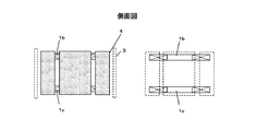
また、図2の破線で示しているように、磁場発生用コイル1b、1cから発生する磁束2とは反対側に発生する、超電導回転機に利用されない磁束の影響を抑制するために、磁気遮蔽体4sを設けてもよい。さらに、図2に示す例では、2つの磁場発生用コイル1b、1cは、ロータである超電導バルク体4の外側に配置されているが、磁場発生用コイル1b、1cの位置は必ずしも外側である必要はない。例えば、図4に示すように、2つの磁場発生用コイル1b、1cが、ロータである超電導バルク体4の内側にあってもよい。なお、図4は、超電導回転機から電機子コイル3を取り除いた場合の側面図を示しており、以下、側面図については、電機子コイル3を取り除いた場合の側面図として示す。
Further, as shown by the broken line in FIG. 2, in order to suppress the influence of the magnetic flux that is generated on the side opposite to the
本発明に用いる超電導バルク体(例えば、第1実施形態や第2実施形態で用いる超電導バルク体4)は、磁気遮蔽効果を生じるものであれば特に材料系を限定するものではないが、磁気遮蔽効果が高い超電導材料が好ましい。超電導材料としては、金属超電導体、酸化物超電導体等が挙げられる。
The superconducting bulk body used in the present invention (for example, the superconducting
金属超電導体としては、NbTi、Nb3Sn等が挙げられる。一方、酸化物超電導体の例としては、例えば、Bi-Sr-Ca-Cu-O系やRE-Ba-Cu-O系酸化物超電導体が挙げられる。ここで、REは、希土類元素から選ばれた少なくとも1つの元素であり、例えば、Y,Eu,Gd,Dy,Er,Sm,La,Ce,Pr,Nd等である。酸化物超電導体の中で、REBa2Cu3Ox相(123相)のバルク体中にRE2BaCuO5相(211相)が微細分散した酸化物超電導体は、臨界電流密度が高くピン止め力が強いので、磁気遮蔽効果も高く、本発明に用いる超電導バルク体としてより好ましい。酸化物超電導体では、分散している211相の粒子(分散粒)がピン止め点として作用する。よって、そのピン止め効果を十分得るためには211相は4モル%以上であることがより好ましい。更に好ましくは6モル%以上である。 Examples of the metal superconductor include NbTi and Nb 3 Sn. On the other hand, examples of oxide superconductors include Bi-Sr-Ca-Cu-O-based and RE-Ba-Cu-O-based oxide superconductors. Here, RE is at least one element selected from rare earth elements, such as Y, Eu, Gd, Dy, Er, Sm, La, Ce, Pr, and Nd. Among oxide superconductors, oxide superconductors in which the RE 2 BaCuO 5 phase (211 phase) is finely dispersed in the REBa 2 Cu 3 O x phase (123 phase) bulk are pinned with high critical current density. Since the force is strong, the magnetic shielding effect is also high, which is more preferable as the superconducting bulk material used in the present invention. In the oxide superconductor, dispersed 211-phase particles (dispersed particles) act as pinning points. Therefore, in order to sufficiently obtain the pinning effect, the 211 phase is more preferably 4 mol% or more. More preferably, it is 6 mol% or more.
また、酸化物超電導体では、超電導相である123相がマトリックスとなるので、通常、そのマトリックスに分散する211相は50モル%未満となる。更に、211相が微細分散しているとピン止め効果が得られるが、211相が40モル%以下であると、123相が良好な結晶性となり、より優れた遮蔽効果が得られる。更に好ましくは35モル%以下である。 In the oxide superconductor, the 123 phase, which is a superconducting phase, is a matrix, and the 211 phase dispersed in the matrix is usually less than 50 mol%. Further, if the 211 phase is finely dispersed, a pinning effect can be obtained, but if the 211 phase is 40 mol% or less, the 123 phase has good crystallinity and a more excellent shielding effect can be obtained. More preferably, it is 35 mol% or less.
さらに、RE-Ba-Cu-O系酸化物超電導体は、溶融法で結晶成長させて作製して得られる単結晶状の擬単結晶からなる酸化物超電導体がより好ましい。ここで、単結晶状の擬単結晶としているのは、単結晶の123相中に211相が例えば1μm程度の微細に分散した結晶相であるからである。よって、単結晶状の酸化物超電導体では、123相がバルク体全体で同一結晶方位に揃い、配向している。また、RE-Ba-Cu-O系酸化物超電導体では、超電導相である123相の結晶のc軸を回転機の動径方向に向けた方が好ましい。特に、単結晶状のRE-Ba-Cu-O系酸化物超電導体の場合には、結晶のc軸を動径方向に向けた効果が顕著に表れる。 Further, the RE-Ba-Cu-O-based oxide superconductor is more preferably an oxide superconductor made of a single-crystal quasi-single crystal obtained by crystal growth by a melting method. Here, the reason why the single crystal quasi-single crystal is used is that the 211 phase is a finely dispersed crystal phase of, for example, about 1 μm in the 123 phase of the single crystal. Therefore, in the single-crystal oxide superconductor, the 123 phases are aligned and aligned in the same crystal orientation in the entire bulk body. In the RE-Ba-Cu-O-based oxide superconductor, it is preferable that the c-axis of the 123-phase crystal, which is a superconducting phase, be oriented in the radial direction of the rotating machine. In particular, in the case of a single crystal RE-Ba-Cu-O-based oxide superconductor, the effect of directing the c-axis of the crystal in the radial direction is prominent.
また、本発明に用いる磁場発生用コイル(例えば、第1実施形態の磁場発生用コイル1aや第2実施形態の磁場発生用コイル1b、1c)は、磁場を発生できるものであれば特に制限を設けるものではないが、例えば、通常の電磁石として使用される銅、アルミニウム、銀や合金等の金属の線材をコイルにしたものが使用できる。更に、強磁場を発生できるものがより好ましく、例えば、超電導体の線材を使用したコイルがより好ましい。超電導体は電気抵抗がゼロで大きな電流を通電できるので、線材としてコイルに用いると強力な磁場を発生できる。超電導体の線材を用いたコイルとしては、例えば、NbTiやNb3Snなどの金属系超電導体の線材を用いたコイルやBi-Sr-Ca-Cu-O系やRE-Ba-Cu-O系の酸化物系超電導体の線材を用いたコイルが挙げられる。また、本発明の磁場発生用コイルの形状はパンケーキ状という単純形状での巻線でよいため、酸化物系超電導体のような脆性系材料の線材であっても比較的容易に巻線できるという利点もある。また、磁場発生用コイルに磁心を設けてもよい。
Further, the magnetic field generating coil used in the present invention (for example, the magnetic
図5は、超電導バルク体によって形成される隙間の非遮蔽部を示す図である。上述のように、超電導バルク体を電機子コイル3に対して回転方向に離散的に配設することにより、図1の磁場発生用コイル1a(または図2の磁場発生用コイル1b、1b)から発生する磁束2の遮蔽部5と非遮蔽部6とを交互に形成する。ここで、非遮蔽部6を形成する、隣り合う超電導バルク体8a、8bによって形成される隙間が、磁場発生用コイルから遠方に比べて近傍が狭くなっている方が、より高効率、高出力の超電導回転機とすることができる。これは、磁場発生用コイルから発生する磁束密度が、磁場発生用コイルから離れるほど小さくなるので、前記のように非遮蔽部の隙間を磁場発生用コイルからの距離に合わせて変えることによって、均一な磁場を構成する界磁が得られるからである。
FIG. 5 is a diagram showing a non-shielding portion of a gap formed by the superconducting bulk body. As described above, the superconducting bulk body is discretely disposed in the rotation direction with respect to the
図5(a)は、図1に示した第1実施形態における超電導バルク体4によって形成される隙間を示している。図5(a)に示すように、磁場発生用コイル1aが隣り合う超電導バルク体8a、8bで囲まれた中央に位置するので、非遮蔽部となる隙間は、磁場発生用コイル1aから近傍の隙間S1と磁場発生用コイル1aから遠方の隙間S2との関係で、S1<S2となる方が、より好ましくなる。なお、図5(a)に示す形状以外のものであっても、S1<S2となるのであれば、形状は限定されない。
FIG. 5A shows a gap formed by the superconducting
図5(b)は、図2に示した第2実施形態における超電導バルク体4によって形成される隙間を示している。図5(b)に示すように、2つの磁場発生用コイル1b、1cが対向して配設され、隣り合う超電導バルク体8a、8bが2つの磁場発生用コイル1b、1cの間に配設されているので、非遮蔽部における回転軸方向の両端部の隙間S2が、中央部の隙間S1よりも小さくなる方が好ましい。即ち、S1>S2の関係となるのが、より好ましい。なお、図5(b)に示す形状以外のものであっても、S1>S2となるのであれば、形状は限定されない。
FIG. 5B shows a gap formed by the superconducting
また、図1の第1実施形態及び図2の第2実施形態では、超電導バルク体4の形状は瓦状であり、超電導バルク体4が同心円を形成するように配設されているが、超電導バルク体の形状は、磁場発生用コイルの磁場を遮蔽できればよく、必ずしも瓦形状である必要はない。例えば、図6(a)に示すように、超電導バルク体9が離散的に配設され、磁束2の遮蔽部5と非遮蔽部6とが交互に形成されるならば、製作が容易な角柱板形状などの四角形状でもよい。また、超電導バルク体9が単結晶状のRE-Ba-Cu-O系酸化物超電導体である場合には、図6(b)に示すように、結晶のc軸を動径方向に向けた方がより好ましい。RE-Ba-Cu-O系酸化物超電導体の臨界電流密度は、結晶のc軸に対して垂直な面内で超電導電流が流れる場合が最も大きくなり、磁気遮蔽電流も同様であるので、同結晶のc軸を動径方向に向けた方がより高い磁気遮蔽効果が得られる。
Moreover, in 1st Embodiment of FIG. 1 and 2nd Embodiment of FIG. 2, the shape of the superconducting
図7は、第2実施形態において、超電導バルク体に、溶融法で作製した瓦形状の単結晶状のGd-Ba-Cu-O系酸化物超電導体を用い、結晶のc軸を動径方向に向けて周方向に4個離散的に配設した場合の超電導回転機を示す図である。図7に示すように、超電導バルク体10に単結晶状のGd-Ba-Cu-O系酸化物超電導体を用いると、磁場発生用コイル1b、1cから発生した磁場(磁束2)は、超電導バルク体10の4箇所の隙間から濃縮して外側へ出る。界磁磁極としては、磁場の強い超電導バルク体10によって形成される隙間部分と磁場の弱い超電導体部分とを合わせて計8極の磁極となる。超電導バルク体10は、より効果的に磁気遮蔽できるので、磁場発生用コイル1b、1cからより強い磁場を発生させて、また、界磁に磁場の強い部分と磁場の弱い部分との強弱をより明確にでき、より高効率、より高出力が得られる、超電導バルク体を用いた超電導回転機を提供することができる。
FIG. 7 shows a second embodiment in which a tile-shaped single-crystal Gd—Ba—Cu—O-based oxide superconductor manufactured by a melting method is used as a superconducting bulk body, and the c-axis of the crystal is in the radial direction. It is a figure which shows the superconducting rotary machine at the time of arranging four pieces discretely in the circumferential direction toward this. As shown in FIG. 7, when a single crystal Gd—Ba—Cu—O-based oxide superconductor is used for the
図8は、第3実施形態を示し、第1実施形態における超電導回転機とは超電導バルク体の形状が異なる超電導回転機を示す図である。なお、図8の上段は、第3実施形態の超電導回転機の断面図を示し、図8の下段は、該超電導回転機の側面図を示している。第1実施形態との相違点は、隣り合う超電導バルク体によって形成される隙間が軸方向にわたって間隔が一定でない点である。なお、図5(a)に示したようなものであってもよい。第1実施形態のように、1つの磁場発生用コイル1aが超電導バルク体4の内側に配設されている場合、図8(a)に示すように、隣り合う超電導バルク体11によって形成される隙間が、磁場が強くなる中央部で狭くなっている。図8(a)に示す例は、隣り合う超電導バルク体11によって形成される隙間の幅は連続的に変化しているが、図8(b)に示すように、超電導バルク体12の横幅を段階的に変化させてもよい。
FIG. 8 is a diagram showing a superconducting rotator in which the shape of the superconducting bulk body is different from that of the superconducting rotator in the first embodiment, showing the third embodiment. 8 shows a cross-sectional view of the superconducting rotating machine of the third embodiment, and the lower part of FIG. 8 shows a side view of the superconducting rotating machine. The difference from the first embodiment is that the gap formed by adjacent superconducting bulk bodies is not constant in the axial direction. It may be as shown in FIG. When one magnetic
以上の構成とすると、磁束の非遮蔽部である隣り合う超電導バルク体によって形成される隙間から出てくる磁場の軸方向の均一性が高まり、より高効率、より高出力が得られる、超電導バルク体を用いた超電導回転機を提供することができる。 With the above configuration, the superconducting bulk that increases the axial uniformity of the magnetic field that emerges from the gap formed by the adjacent superconducting bulk body that is the non-shielding part of the magnetic flux, resulting in higher efficiency and higher output. A superconducting rotating machine using a body can be provided.
図9は、第4実施形態を示し、第2実施形態における超電導回転機とは、超電導バルク体の形状が異なる超電導回転機を示す側面図である。第3実施形態と同様、第2実施形態との相違点は、隣り合う超電導バルク体によって形成される隙間が軸方向にわたって間隔が一定でない点である。なお、図5(b)に示したようなものであってもよい。第2実施形態のように、2つの磁場発生用コイル1b、1cが超電導バルク体4の外側に配設されている場合、図9(a)に示すように、隣り合う超電導バルク体13によって形成される隙間が、磁場発生用コイルから遠方になればなるほど狭くなっている。図9(a)に示す例は、隣り合う超電導バルク体13によって形成される隙間の幅は連続的に変化しているが、図9(b)に示すように、超電導バルク体14の横幅を段階的に変化させてもよい。
FIG. 9 shows a fourth embodiment, and is a side view showing a superconducting rotator in which the shape of the superconducting bulk body is different from the superconducting rotator in the second embodiment. Similar to the third embodiment, the difference from the second embodiment is that the gap formed by adjacent superconducting bulk bodies is not constant in the axial direction. It may be as shown in FIG. When the two magnetic
以上の構成にすると、磁束の非遮蔽部である隣り合う超電導バルク体によって形成される隙間から出てくる磁場の軸方向の均一性が高まり、より高効率、より高出力が得られる、超電導バルク体を用いた超電導回転機を提供することができる。 With the above configuration, the superconducting bulk that increases the axial uniformity of the magnetic field coming out from the gap formed by the adjacent superconducting bulk body that is the non-shielding part of the magnetic flux, and can obtain higher efficiency and higher output. A superconducting rotating machine using a body can be provided.
図10は、第5実施形態を示し、第1実施形態または第2実施形態の超伝導回転機に、超電導バルク体が移動できる機構を備えた場合の動径方向の断面図である。第1実施形態や第2実施形態との相違点は、ロータを形成している超電導バルク体16が動径方向に移動できる機構を有している点である。更に、電機子コイル15も動径方向に移動できる機構を有していてもよい。超電導バルク体16が動径方向に移動すると、磁場発生用コイルで発生させた磁場(磁束)を濃縮させて強い磁場を得ることができる。これは、まず、磁場発生用コイルで磁場を発生させ、その後に、不図示の駆動機構を用いて、超電導バルク体16及び電機子コイル15が動径方向に径が小さくなるように移動させることにより、磁場発生用コイルで予め発生させたより広範囲の磁場を濃縮することができ、磁極の磁場強度を強めることができる。以上の構成とすると、より高効率、より高出力が得られる、超電導バルク体を用いた超電導回転機を提供することができる。
FIG. 10 shows the fifth embodiment, and is a radial cross-sectional view when the superconducting rotating machine of the first embodiment or the second embodiment is provided with a mechanism capable of moving the superconducting bulk body. The difference from the first and second embodiments is that the
図11は、第6実施形態を示し、第2実施形態の構成を回転軸方向で多段に組み合わせた超電導回転機を示す側面図である。なお、図示していないが、第1実施形態の構成を多段に組み合わせることも可能である。第2実施形態との相違点は、4つの磁場発生用コイル1d、1e、1f、1gが用いられ、回転軸方向に多段構成(3段構成)になっている点である。以上の構成とすると、より高効率、より高出力が得られる、超電導バルク体を用いた超電導回転機を提供することができる。
FIG. 11 is a side view showing a superconducting rotating machine according to the sixth embodiment in which the configuration of the second embodiment is combined in multiple stages in the rotation axis direction. Although not shown, the configuration of the first embodiment can be combined in multiple stages. The difference from the second embodiment is that four magnetic
図12は、第7実施形態を示し、第2実施形態における超電導回転機とは超電導バルク体の構成が異なる超電導回転機を示す側面図である。なお、図示していないが、第1実施形態の超伝導回転機にこのような超電導バルク体を用いることも可能である。第2実施形態との相違点は、外観上は、第2実施形態と同様であるが、ロータを形成している超電導バルク体17の内部が空洞18になっており、超電導バルク体17の中心部を、磁気遮蔽効果を損なわない範囲でくり抜いている。以上の構成とすると、磁気遮蔽効果を有する範囲内で、超電導バルク体の内部を取り除くことにより、超電導バルク体の機械的強度を維持しながら、磁気遮蔽効果の性能を低下させずに軽量化することが可能となる。
FIG. 12 is a side view showing a superconducting rotator in which the configuration of the superconducting bulk body is different from that of the superconducting rotator in the second embodiment, showing the seventh embodiment. Although not shown, it is also possible to use such a superconducting bulk body for the superconducting rotating machine of the first embodiment. The difference from the second embodiment is the same as the second embodiment in appearance, but the inside of the
図13は、第8実施形態を示し、第2実施形態における超電導回転機とは超電導バルク体の構成が異なる超電導回転機を示す図である。なお、図示していないが、第1実施形態の超伝導回転機にこのような超電導バルク体を用いることも可能である。第2実施形態との相違点は、ロータの1つである遮蔽部5が複数個の要素部材20の超電導バルク体19からなり、個々の要素部材20が動径方向に積層された構造を有する点である。以上の構成とすると、製作が比較的容易な小型の超電導ブロック(要素部材20)を用いて、性能を低下させずにより大型の回転機にも適用可能となる。更に、図13に示すように、隣り合う層ごとに要素部材20間の境界面の位置がずれるように積層された積層構造にすることにより、積層界面からの磁束漏れを抑制できるので、より高い磁気遮蔽効果が得られる。各要素部材20の接合界面が超電導接合されている場合は磁束の漏れが少ないが、常電導体を接合体として常電導接合されている場合や絶縁体を接合体として接合されている場合には、磁束の漏れが多くなるので前記積層構造にする効果が大きい。
FIG. 13 is a diagram illustrating a superconducting rotator in which the configuration of the superconducting bulk body is different from that of the superconducting rotator in the second embodiment according to the eighth embodiment. Although not shown, it is also possible to use such a superconducting bulk body for the superconducting rotating machine of the first embodiment. The difference from the second embodiment is that the shielding
図14は、第9実施形態を示し、第1実施形態及び第2実施形態における超電導回転機とは超電導バルク体の構成が異なる超電導回転機の回転軸方向から見た動径方向の断面図である。第1実施形態や第2実施形態との相違点は、ロータである超電導バルク体21を8個にし、遮蔽部及び非遮蔽分を合わせて回転方向に16分割に増加して、16極の界磁とした点である。以上のように構成すると、より高効率、より高出力が得られ、電気吸引力の発生箇所が多くなるので大きなトルクが得られ、大型の回転機に適用する場合により好ましい。
FIG. 14 shows a ninth embodiment, and is a radial cross-sectional view of a superconducting rotating machine having a superconducting bulk body having a different configuration from the superconducting rotating machine in the first and second embodiments, as viewed from the rotational axis direction. is there. The difference from the first embodiment and the second embodiment is that the
図15は、第10実施形態に係る超電導回転機を示す図である。第1実施形態や第2実施形態との相違点は、超電導バルク体22と磁場発生用コイル23とを固定してともにロータとし、更に、超電導バルク体22を2段に、磁場発生用コイル23を3段に組み合わせて、80極の界磁24として点である。ここで、2段に配置した超電導バルク体を千鳥状に配列し、磁場発生用コイル23に流れる電流27の向きを交互に逆にして、それぞれの段における非遮蔽部からでる磁束の向きがS向き25及びN向き26とで逆になって段間の磁束の影響を受け難くしている。以上のように構成すると、更に大型の回転機に適用する場合に好ましい。
FIG. 15 is a diagram showing a superconducting rotating machine according to the tenth embodiment. The difference from the first embodiment and the second embodiment is that the
以上のように、本発明の第1〜第10実施形態について説明したが、これらの形態を2つ以上組み合わせてもよい。例えば、第4実施形態で示した形状の超電導バルク体を第9実施形態で用いてもよく、第7実施形態で示した超電導バルク体を第5実施形態に用いてもよい。 As described above, although the first to tenth embodiments of the present invention have been described, two or more of these forms may be combined. For example, the superconducting bulk body having the shape shown in the fourth embodiment may be used in the ninth embodiment, and the superconducting bulk body shown in the seventh embodiment may be used in the fifth embodiment.
本発明によれば、超電導バルク体を着磁するプロセスを省略できる、超電導バルク体を用いた超電導回転機を提供することができるので、酸化物超電導体の工業上の利用範囲が拡大する。 According to the present invention, it is possible to provide a superconducting rotating machine using a superconducting bulk body that can omit the process of magnetizing the superconducting bulk body, so that the industrial application range of the oxide superconductor is expanded.
1a〜1g 磁場発生用コイル
2 磁束
3 電機子コイル
3a 電機子コイルを分割した場合の上部の電機子コイル
3b 電機子コイルを分割した場合の下部の電機子コイル
3c 電機子コイルの分割部
4 超電導バルク体
4s 磁場発生用コイル1b、1cから発生する磁束2とは反対側の磁束を遮蔽する遮蔽体
5 遮蔽部(超電導バルク体4)
6 非遮蔽部
7 非遮蔽部の隙間
8a、8b 超電導バルク体(遮蔽部)
9 角柱板形状の超電導バルク体(遮蔽部)
10 瓦形状の単結晶状酸化物超電導体からなる超電導バルク体
11 超電導バルク体(隙間(非遮蔽部)が中央コイルから連続的に広くなっている)
12 超電導バルク体(隙間(非遮蔽部)が中央コイルからステップ状に広くなっている)
13 超電導バルク体(隙間(非遮蔽部)が両端コイルから中央に連続的に広くなっている)
14 超電導バルク体(隙間(非遮蔽部)が両端コイルから中央にステップ状に広くなっている)
15 移動できる機構を有する電機子コイル
16 移動できる機構を有する超電導バルク体
17 超電導バルク体
18 空洞
19 積層構造の超電導バルク体
20 超電導バルク体を構成する要素部材
21 16極の界磁を形成する超電導バルク体
22 80極の界磁を形成する超電導バルク体
23 80極の界磁を形成する磁場発生用コイル
24 80極の界磁
25 磁束(S向き)
26 磁束(N向き)
27 電流
1a to 1g Magnetic
6 Non-shielding part 7
9 Superconducting bulk material with a prismatic plate (shielding part)
10 Superconducting bulk body made of tile-shaped single-
12 Superconducting bulk body (gap (non-shielding part) widens in steps from the central coil)
13 Superconducting bulk body (gap (non-shielding part) is continuously widened from both end coils to the center)
14 Superconducting bulk body (gap (non-shielding part) widens stepwise from both ends coil to the center)
DESCRIPTION OF
26 Magnetic flux (N direction)
27 Current
Claims (10)
電機子コイルを有するステータと、を備え、
前記電機子コイルが、前記超電導バルク体の外周側に配置され、
前記超電導バルク体が、前記電機子コイルに対して前記磁束の遮蔽部と非遮蔽部とを交互に形成するように複数配設されていることを特徴とする超電導回転機。 A field having a magnetic field generating coil and a rotor made of a superconducting bulk body that shields magnetic flux generated from the magnetic field generating coil;
A stator having an armature coil,
The armature coil is disposed on the outer peripheral side of the superconducting bulk body,
A superconducting rotating machine, wherein a plurality of the superconducting bulk bodies are arranged so as to alternately form shielding portions and non-shielding portions of the magnetic flux with respect to the armature coil.
Priority Applications (1)
| Application Number | Priority Date | Filing Date | Title |
|---|---|---|---|
| JP2009209680A JP5353585B2 (en) | 2009-09-10 | 2009-09-10 | Superconducting rotating machine |
Applications Claiming Priority (1)
| Application Number | Priority Date | Filing Date | Title |
|---|---|---|---|
| JP2009209680A JP5353585B2 (en) | 2009-09-10 | 2009-09-10 | Superconducting rotating machine |
Publications (2)
| Publication Number | Publication Date |
|---|---|
| JP2011061994A true JP2011061994A (en) | 2011-03-24 |
| JP5353585B2 JP5353585B2 (en) | 2013-11-27 |
Family
ID=43948956
Family Applications (1)
| Application Number | Title | Priority Date | Filing Date |
|---|---|---|---|
| JP2009209680A Expired - Fee Related JP5353585B2 (en) | 2009-09-10 | 2009-09-10 | Superconducting rotating machine |
Country Status (1)
| Country | Link |
|---|---|
| JP (1) | JP5353585B2 (en) |
Cited By (3)
| Publication number | Priority date | Publication date | Assignee | Title |
|---|---|---|---|---|
| JP2018061435A (en) * | 2013-09-26 | 2018-04-12 | ドミニオン オルタナティブ エナジー、エルエルシー | Superconduction motor and dynamo-electric generator |
| WO2021140578A1 (en) * | 2020-01-07 | 2021-07-15 | 須山弘次 | Power generator using magnetic force shielding using superconductor, motor, and propulsion machine |
| FR3119043A1 (en) * | 2021-01-21 | 2022-07-22 | Safran | PROTECTION OF THE COILS OF AN ELECTRIC MACHINE |
Citations (14)
| Publication number | Priority date | Publication date | Assignee | Title |
|---|---|---|---|---|
| JPH02164258A (en) * | 1988-12-16 | 1990-06-25 | Matsushita Electric Ind Co Ltd | Brushless motor |
| JPH0717774A (en) * | 1993-06-22 | 1995-01-20 | Railway Technical Res Inst | Bonding structure of oxide superconductor, bonding method and magnetic shielding material |
| JPH0787724A (en) * | 1993-09-15 | 1995-03-31 | Imura Zairyo Kaihatsu Kenkyusho:Kk | Superconducting motor |
| JPH07312885A (en) * | 1994-05-16 | 1995-11-28 | Mitsubishi Materials Corp | Superconducting actuator |
| JPH08317631A (en) * | 1995-05-15 | 1996-11-29 | Toyota Motor Corp | Superconducting motor |
| JPH11126927A (en) * | 1997-10-24 | 1999-05-11 | Dowa Mining Co Ltd | Oxide superconducting magnetic shield material and its manufacture |
| JPH11278952A (en) * | 1998-03-27 | 1999-10-12 | Dowa Mining Co Ltd | Oxide superconducter bonded body, its production and superconducting magnetic shielding material |
| JP2002369494A (en) * | 2001-06-05 | 2002-12-20 | Japan Science & Technology Corp | Superconducting motor |
| JP2004236446A (en) * | 2003-01-30 | 2004-08-19 | Japan Science & Technology Agency | Generator using high-temperature superconducting bulk material |
| JP2004235625A (en) * | 2003-01-09 | 2004-08-19 | Fukui Univ | Magnetizing device for bulk superconductor, and magnetizing method and superconducting synchronous machine |
| JP2005224000A (en) * | 2004-02-04 | 2005-08-18 | Univ Of Fukui | Superconducting synchronous machine |
| JP2007060744A (en) * | 2005-08-22 | 2007-03-08 | Sumitomo Electric Ind Ltd | Motor for both power generation/driving and vehicle equipped with that motor |
| JP2007060747A (en) * | 2005-08-22 | 2007-03-08 | Sumitomo Electric Ind Ltd | Superconducting motor and vehicle equipped with that motor |
| WO2007029823A1 (en) * | 2005-09-09 | 2007-03-15 | National University Corporation Tokyo University Of Marine Science And Technology | Superconducting synchronous machine |
-
2009
- 2009-09-10 JP JP2009209680A patent/JP5353585B2/en not_active Expired - Fee Related
Patent Citations (14)
| Publication number | Priority date | Publication date | Assignee | Title |
|---|---|---|---|---|
| JPH02164258A (en) * | 1988-12-16 | 1990-06-25 | Matsushita Electric Ind Co Ltd | Brushless motor |
| JPH0717774A (en) * | 1993-06-22 | 1995-01-20 | Railway Technical Res Inst | Bonding structure of oxide superconductor, bonding method and magnetic shielding material |
| JPH0787724A (en) * | 1993-09-15 | 1995-03-31 | Imura Zairyo Kaihatsu Kenkyusho:Kk | Superconducting motor |
| JPH07312885A (en) * | 1994-05-16 | 1995-11-28 | Mitsubishi Materials Corp | Superconducting actuator |
| JPH08317631A (en) * | 1995-05-15 | 1996-11-29 | Toyota Motor Corp | Superconducting motor |
| JPH11126927A (en) * | 1997-10-24 | 1999-05-11 | Dowa Mining Co Ltd | Oxide superconducting magnetic shield material and its manufacture |
| JPH11278952A (en) * | 1998-03-27 | 1999-10-12 | Dowa Mining Co Ltd | Oxide superconducter bonded body, its production and superconducting magnetic shielding material |
| JP2002369494A (en) * | 2001-06-05 | 2002-12-20 | Japan Science & Technology Corp | Superconducting motor |
| JP2004235625A (en) * | 2003-01-09 | 2004-08-19 | Fukui Univ | Magnetizing device for bulk superconductor, and magnetizing method and superconducting synchronous machine |
| JP2004236446A (en) * | 2003-01-30 | 2004-08-19 | Japan Science & Technology Agency | Generator using high-temperature superconducting bulk material |
| JP2005224000A (en) * | 2004-02-04 | 2005-08-18 | Univ Of Fukui | Superconducting synchronous machine |
| JP2007060744A (en) * | 2005-08-22 | 2007-03-08 | Sumitomo Electric Ind Ltd | Motor for both power generation/driving and vehicle equipped with that motor |
| JP2007060747A (en) * | 2005-08-22 | 2007-03-08 | Sumitomo Electric Ind Ltd | Superconducting motor and vehicle equipped with that motor |
| WO2007029823A1 (en) * | 2005-09-09 | 2007-03-15 | National University Corporation Tokyo University Of Marine Science And Technology | Superconducting synchronous machine |
Non-Patent Citations (1)
| Title |
|---|
| JPN6012067366; 鈴木達矢, 寺尾悠, 関野正樹, 大崎博之: '高温超電導コイルとバルク超電導磁気シールド材を併用した界磁を有する同期モータの研究' 第21回電磁力関連のダイナミクスシンポジウム講演論文集 , 20090521, P.467-472, 電気学会 * |
Cited By (4)
| Publication number | Priority date | Publication date | Assignee | Title |
|---|---|---|---|---|
| JP2018061435A (en) * | 2013-09-26 | 2018-04-12 | ドミニオン オルタナティブ エナジー、エルエルシー | Superconduction motor and dynamo-electric generator |
| WO2021140578A1 (en) * | 2020-01-07 | 2021-07-15 | 須山弘次 | Power generator using magnetic force shielding using superconductor, motor, and propulsion machine |
| FR3119043A1 (en) * | 2021-01-21 | 2022-07-22 | Safran | PROTECTION OF THE COILS OF AN ELECTRIC MACHINE |
| WO2022157441A1 (en) * | 2021-01-21 | 2022-07-28 | Safran | Protection for the coils of an electric machine |
Also Published As
| Publication number | Publication date |
|---|---|
| JP5353585B2 (en) | 2013-11-27 |
Similar Documents
| Publication | Publication Date | Title |
|---|---|---|
| US11575301B2 (en) | Dual rotor electrical machines | |
| US6441521B1 (en) | Hybrid superconducting motor/generator | |
| US7489060B2 (en) | Superconducting rotating machines with stationary field coils | |
| US7492073B2 (en) | Superconducting rotating machines with stationary field coils | |
| US8471660B2 (en) | Assembly for magnetization of rare-earth permanent magnets | |
| US7382072B2 (en) | Generator | |
| KR101098459B1 (en) | Superconducting coil device and inductor type synchronizer | |
| KR20170070003A (en) | Superconducting current pump | |
| JP2012050312A (en) | Axial gap type brushless motor | |
| US11502590B2 (en) | Radial-gap type superconducting synchronous machine, magnetizing apparatus, and magnetizing method | |
| CA2711363C (en) | Superconducting magnetizer | |
| JP5353585B2 (en) | Superconducting rotating machine | |
| EP2897266B1 (en) | Superconducting field-pole magnet | |
| WO2020069908A1 (en) | Rotor and machine having superconducting permanent magnets | |
| US7291958B2 (en) | Rotating back iron for synchronous motors/generators | |
| CN109979705B (en) | Sintered magnetic body, magnet, motor, wind turbine, and method for manufacturing sintered magnetic body | |
| RU2180156C1 (en) | Superconductor synchronous machine | |
| US20220103056A1 (en) | Azimuthal or polodial flux machines | |
| Karbowiak et al. | The application of multi-pole bonded magnets in electric motors | |
| CN112930641A (en) | Motor and hybrid electric vehicle |
Legal Events
| Date | Code | Title | Description |
|---|---|---|---|
| A621 | Written request for application examination |
Free format text: JAPANESE INTERMEDIATE CODE: A621 Effective date: 20110816 |
|
| A977 | Report on retrieval |
Free format text: JAPANESE INTERMEDIATE CODE: A971007 Effective date: 20121212 |
|
| A131 | Notification of reasons for refusal |
Free format text: JAPANESE INTERMEDIATE CODE: A131 Effective date: 20121225 |
|
| A521 | Written amendment |
Free format text: JAPANESE INTERMEDIATE CODE: A523 Effective date: 20130212 |
|
| TRDD | Decision of grant or rejection written | ||
| A01 | Written decision to grant a patent or to grant a registration (utility model) |
Free format text: JAPANESE INTERMEDIATE CODE: A01 Effective date: 20130730 |
|
| A61 | First payment of annual fees (during grant procedure) |
Free format text: JAPANESE INTERMEDIATE CODE: A61 Effective date: 20130812 |
|
| R151 | Written notification of patent or utility model registration |
Ref document number: 5353585 Country of ref document: JP Free format text: JAPANESE INTERMEDIATE CODE: R151 |
|
| S533 | Written request for registration of change of name |
Free format text: JAPANESE INTERMEDIATE CODE: R313533 |
|
| R350 | Written notification of registration of transfer |
Free format text: JAPANESE INTERMEDIATE CODE: R350 |
|
| LAPS | Cancellation because of no payment of annual fees |