EP2477024A2 - Analyzer - Google Patents
Analyzer Download PDFInfo
- Publication number
- EP2477024A2 EP2477024A2 EP12150820A EP12150820A EP2477024A2 EP 2477024 A2 EP2477024 A2 EP 2477024A2 EP 12150820 A EP12150820 A EP 12150820A EP 12150820 A EP12150820 A EP 12150820A EP 2477024 A2 EP2477024 A2 EP 2477024A2
- Authority
- EP
- European Patent Office
- Prior art keywords
- light
- slit
- optical element
- numerical aperture
- reaction tubes
- Prior art date
- Legal status (The legal status is an assumption and is not a legal conclusion. Google has not performed a legal analysis and makes no representation as to the accuracy of the status listed.)
- Granted
Links
Images



Classifications
-
- G—PHYSICS
- G01—MEASURING; TESTING
- G01N—INVESTIGATING OR ANALYSING MATERIALS BY DETERMINING THEIR CHEMICAL OR PHYSICAL PROPERTIES
- G01N21/00—Investigating or analysing materials by the use of optical means, i.e. using sub-millimetre waves, infrared, visible or ultraviolet light
- G01N21/17—Systems in which incident light is modified in accordance with the properties of the material investigated
- G01N21/25—Colour; Spectral properties, i.e. comparison of effect of material on the light at two or more different wavelengths or wavelength bands
- G01N21/251—Colorimeters; Construction thereof
- G01N21/253—Colorimeters; Construction thereof for batch operation, i.e. multisample apparatus
-
- G—PHYSICS
- G01—MEASURING; TESTING
- G01J—MEASUREMENT OF INTENSITY, VELOCITY, SPECTRAL CONTENT, POLARISATION, PHASE OR PULSE CHARACTERISTICS OF INFRARED, VISIBLE OR ULTRAVIOLET LIGHT; COLORIMETRY; RADIATION PYROMETRY
- G01J3/00—Spectrometry; Spectrophotometry; Monochromators; Measuring colours
- G01J3/28—Investigating the spectrum
- G01J3/30—Measuring the intensity of spectral lines directly on the spectrum itself
- G01J3/36—Investigating two or more bands of a spectrum by separate detectors
-
- G—PHYSICS
- G01—MEASURING; TESTING
- G01N—INVESTIGATING OR ANALYSING MATERIALS BY DETERMINING THEIR CHEMICAL OR PHYSICAL PROPERTIES
- G01N21/00—Investigating or analysing materials by the use of optical means, i.e. using sub-millimetre waves, infrared, visible or ultraviolet light
- G01N21/17—Systems in which incident light is modified in accordance with the properties of the material investigated
- G01N21/25—Colour; Spectral properties, i.e. comparison of effect of material on the light at two or more different wavelengths or wavelength bands
- G01N21/255—Details, e.g. use of specially adapted sources, lighting or optical systems
-
- G—PHYSICS
- G01—MEASURING; TESTING
- G01N—INVESTIGATING OR ANALYSING MATERIALS BY DETERMINING THEIR CHEMICAL OR PHYSICAL PROPERTIES
- G01N3/00—Investigating strength properties of solid materials by application of mechanical stress
-
- G—PHYSICS
- G01—MEASURING; TESTING
- G01N—INVESTIGATING OR ANALYSING MATERIALS BY DETERMINING THEIR CHEMICAL OR PHYSICAL PROPERTIES
- G01N3/00—Investigating strength properties of solid materials by application of mechanical stress
- G01N3/02—Details
- G01N3/04—Chucks
-
- G—PHYSICS
- G01—MEASURING; TESTING
- G01N—INVESTIGATING OR ANALYSING MATERIALS BY DETERMINING THEIR CHEMICAL OR PHYSICAL PROPERTIES
- G01N21/00—Investigating or analysing materials by the use of optical means, i.e. using sub-millimetre waves, infrared, visible or ultraviolet light
- G01N21/01—Arrangements or apparatus for facilitating the optical investigation
- G01N21/03—Cuvette constructions
- G01N2021/0325—Cells for testing reactions, e.g. containing reagents
-
- G—PHYSICS
- G01—MEASURING; TESTING
- G01N—INVESTIGATING OR ANALYSING MATERIALS BY DETERMINING THEIR CHEMICAL OR PHYSICAL PROPERTIES
- G01N30/00—Investigating or analysing materials by separation into components using adsorption, absorption or similar phenomena or using ion-exchange, e.g. chromatography or field flow fractionation
- G01N30/02—Column chromatography
- G01N30/62—Detectors specially adapted therefor
- G01N30/74—Optical detectors
-
- G—PHYSICS
- G01—MEASURING; TESTING
- G01N—INVESTIGATING OR ANALYSING MATERIALS BY DETERMINING THEIR CHEMICAL OR PHYSICAL PROPERTIES
- G01N35/00—Automatic analysis not limited to methods or materials provided for in any single one of groups G01N1/00 - G01N33/00; Handling materials therefor
- G01N35/02—Automatic analysis not limited to methods or materials provided for in any single one of groups G01N1/00 - G01N33/00; Handling materials therefor using a plurality of sample containers moved by a conveyor system past one or more treatment or analysis stations
- G01N35/025—Automatic analysis not limited to methods or materials provided for in any single one of groups G01N1/00 - G01N33/00; Handling materials therefor using a plurality of sample containers moved by a conveyor system past one or more treatment or analysis stations having a carousel or turntable for reaction cells or cuvettes
Definitions
- the embodiment of the present invention relates to an analyzer.
- analyzers for analyzing test samples.
- automatic analyzers are devices that dispense test samples such as human blood and urine as well as reagents inside reaction tubes, cause them to react at a constant temperature after they are mixed and stirred, and measure changes from the resulting reactions, in order to measure the concentration and/or activity of the measured substance or enzyme inside the test sample.
- Colorimetric determination and turbidimetric determination are known as the measurement methods are used in this type of automatic analyzer.
- Colorimetric determination refers to a method in which mixtures (reaction solutions in which test samples and reagents are mixed) inside reaction tubes are irradiated with light from a light source (wavelengths of light from the near-ultraviolet band to the near-infrared band) and light obtained through the mixtures is divided into spectra and detected by photodetectors, in order to detect changes (absorbance) in specific wavelength components absorbed by the reaction solution.
- a light source wavelengths of light from the near-ultraviolet band to the near-infrared band
- turbidimetric determination generally irradiates mixtures in which reagents containing latex particles are mixed and stirred with test samples using light from the light source. Therefore, turbidimetric determination refers to a method in which light obtained through the mixture is divided into spectra and detected by photodetectors, in order to detect the turbidity (permeability) of the mixture, associated with the agglutination of latex particles.
- the analyzer comprises an irradiation optical part that irradiates a mixture inside reaction tubes with light from a light source. Moreover, a detection optical part detects light transmitted through the mixture. Moreover, the irradiation optical part comprises a first optical element in which the light source is disposed at the front focal position and concentrates light from the light source. Moreover, a second optical element guides light transmitted through the first optical element to the reaction tubes. In addition, an incident numerical aperture adjustment member is provided at the rear side of the first optical element and adjusts the numerical aperture when light from the light source is incident into the reaction tubes.
- the automatic analyzer comprises reagent bottles 1, reagent racks 2a and 2b, reagent storages 3a and 3b, reaction tubes 4, a reaction disk 5, a test sample containers 6, a disk sampler 7, dispensing arms 8a and 8b, a sampling arm 9, a stirring unit 10, a photometric unit 11, and a washing unit 12.
- the reagent bottles 1 are containers in which reagents that react with various components of test samples are housed.
- the reagent rack 2a is provided in the reagent storage 3a in a state in which the plurality of reagent bottles 1 are housed.
- the reagent rack 2b is provided in the reagent storage 3b in a state in which the multiple reagent bottles 1 are housed.
- the reaction tubes 4 are containers used when the test sample and the reagent are caused to react.
- the multiple reaction tubes 4 are disposed at the circumference of the reaction disk 5.
- test sample containers 6 are containers in which test samples are stored.
- the multiple test sample containers 6 are disposed on top of the disk sampler 7.
- the reagents inside the reagent bottles 1 are dispensed into the reaction tubes 4 by the dispensing arm 8a or the dispensing arm 8b. Moreover, the test samples inside the test sample containers 6 are dispensed into the reaction tubes 4 by the sampling arm 9.
- the reaction tubes 4 into which the test samples and the reagents are dispensed are moved to the position of the stirring unit 10 by the rotation of the reaction disk 5.
- the stirring unit 10 is a unit that stirs the reaction tubes 4 in which the test samples and the reagents are contained and mixes the test samples and the reagents.
- the stirred reaction tubes 4 are moved to the position of the photometric unit 11.
- the photometric unit 11 is a unit that irradiates the reaction tubes 4 with light and measures changes in the absorbance, etc., of the mixture of the test sample and the reagent, in order to carry out component analysis of the test sample.
- the washing unit 12 is a unit that washes the inside of the reaction tubes 4 after the mixture inside the reaction tubes 4 is disposed of, upon completion of component analysis.
- the photometric unit 11 comprises a light source 20, an irradiation optical part 21, a detection optical part 22, a spectroscopic part 23, and a detection part 24.
- the light source 20 side may be referred to as the "front side” and the detection part 24 side may be referred to as the "rear side.”
- the light source 20 has a function of generating light that is irradiated to the reaction tubes 4 through the irradiation optical part 21.
- the light source 20 is a white light source and in the measurement, light between the near-ultraviolet region (340 nm) and the near infrared (850 nm) is used.
- the irradiation optical part 21 is an optical system for guiding the light generated at the light source 20 to the reaction tubes 4.
- the detection optical part 22 is an optical system for guiding the light transmitted through the reaction tubes 4 to the spectroscopic part 23. The irradiation optical part 21 and the detection optical part 22 will be explained in detail subsequently.
- the spectroscopic part 23 has a function of dividing light guided by the detection optical part 22 into spectra by each wavelength.
- the spectroscopic part 23 includes spectroscopic optical elements such as diffraction grating.
- the detection part 24 has a function of detecting the intensity of the light that is divided into spectra by the spectroscopic part 23.
- the detection part 24 includes photodetectors such as PDAs (Photodiode Arrays).
- the irradiation optical part 21 of the photometric unit 11 in the first embodiment comprises a lens 211 (a first optical element), a slit 212 (a first slit), a filter 213, a plane mirror 214, a slit 215 (a second slit), and a concave mirror 216 (a second optical element).
- the lens 211 is disposed at the rear side of the light source 20 and is an optical element for concentrating light from the light source 20.
- the lens 211 is made from an optical lens such as a convex lens.
- the slit 212 is disposed at the rear side of the lens 211 and is an aperture for limiting the luminous flux of the light from the lens 211 (light intensity adjustment).
- the slit 212 may be a transmission type or it may be a reflection type.
- the light source 20 is disposed at the front focal position of the lens 211 and the slit 212 is disposed at the rear focal position of the lens 211. Consequently, the light from the light source 20 is turned into light parallel to an optical axis O1 (refer to Fig. 5 ) of the light source 20 by the lens 211 and only part of this light passes through the slit 212. That is, by limiting some of the light among the light from the light source 20, the size of the beam spot (which will be explained subsequently) and the intensity of light that is incident on the reaction tubes 4 are adjusted.
- the filter 213 is an infrared light cut filter that is disposed at the rear side of the slit 212 and absorbs the thermal components of the light passing through the slit 212. Note that the disposition of the filter 213 is not limited to the rear side of the slit 212. For example, it may be provided between the light source 20 and the lens 211.
- the plane mirror 214 is a mirror that is disposed at the rear side of the filter 213 and reflects the light passing through the slit 212.
- the optical axis of the light reflected by the plane mirror 214 is referred to as an optical axis 02 (refer to Fig. 5 ).
- the slit 215 is disposed at the rear side of the plane mirror 214 and is an aperture for adjusting the numerical aperture (hereinafter may be referred to as the "incident numerical aperture") when the light from the light source 20 is incident into the reaction tube 4, by limiting the luminous flux of the light that is reflected by the plane mirror 214. That is, in the present embodiment, the slit 215 functions as the "incident numerical aperture adjustment member.”
- the slit 215 may be a transmission type or a reflection type. Moreover, instead of the slit 215, it is also possible to dispose a concave mirror or a plane mirror and adjust the luminous flux by means of the reflective effective diameter. In the present embodiment, it may be referred to as the "second slit,” including the concave mirror or the plane mirror.
- the slit 215 may be disposed at the rear side of the concave mirror 216.
- one optical element may serve as the slit 215 and the concave mirror 216.
- the concave mirror 216 is disposed at the rear side of the slit 215 and is an optical element for correcting chromatic aberrations of light passing through the slit 215 and for guiding the corrected light to the reaction tube 4.
- the reasons for using the concave mirror will be explained subsequently.
- the detection optical part 22 of the photometric unit 11 is constituted from a detection optical system comprising a lens 221 (a third optical element), a slit 222 (a third slit), a lens 223 (a fourth optical element), and a slit 224 (a fourth slit).
- the lens 221 is disposed at the rear side of the reaction tube 4 and is an optical element for collimating the light passing through the reaction tube 4.
- the lens 221 is made from, for example, a collimating lens.
- the light passing through the reaction tube 4 is adjusted by the lens 221 so as to be in parallel with respect to an optical axis 03 (refer to Fig. 5 ).
- the slit 222 is disposed at the rear side of the lens 221 and is an aperture for adjusting the numerical aperture (hereinafter may be referred to as a "detection numerical aperture") when the light passing through the reaction tube 4 is detected, by allowing some of the light that is collimated with the lens 221 to pass through.
- the lens 223 is disposed at the rear side of the slit 222 and is an optical element that concentrates the light passing through the slit 222 and guides it to the slit 224.
- the lens 223 is made from an optical lens such as a convex lens.
- the slit 224 is disposed at the rear side of the lens 223 and is an aperture for allowing some of the light that is concentrated at the lens 223 to pass through.
- the light passing through the slit 224 is divided into spectra at the spectroscopic part 23 and is detected by the detection part 24 by each wavelength component.
- the light source 20 is a point light source
- light L0 generated by the light source 20 that is disposed at the front focal position of the lens 211 is turned into light L1, which is parallel to the optical axis O1 of the light source 20, by the lens 211.
- the light L1 passes through the slit 212, it turns into light L2 in which the luminous flux of the L1 is partially limited.
- the light L2 is reflected by the plane mirror 214 after it passes through the filter 213.
- the light L2 that is reflected by the plane mirror 214 reaches the slit 215.
- the light L2 reached the slit 215 turns into light L3 in which the luminous flux is partially limited, as it passes through this slit 215. Accordingly, the light L3 reaches the concave mirror 216.
- the angle at which the light L3 passing through the slit 215 is incident on the concave mirror 216 is preferably equal to or less than 10 degrees with respect to the reflection optical axis 03 of the concave mirror 216.
- Fig. 6 is a graph showing the intensity distribution at the cross-section of the diameter (the beam spot) of the light L4 that is incident on the reaction tube 4.
- the vertical axis indicates the intensity and the horizontal axis indicates the position at the cross-section of the beam spot.
- the light L4 that is reflected by the concave mirror 216 is guided inside the reaction tube 4 and an image is formed inside the reaction tube 4.
- the chromatic aberration problem is solved using the concave mirror 216 as the second optical element.
- Fig. 7 is a graph showing the results of a simulation of the degree of the chromatic aberration at the image forming position inside the reaction tube 4.
- the vertical axis indicates the intensity and the horizontal axis indicates the position at the cross-section of the beam spot.
- the concave mirror 216 is used as the second optical element, there is nearly constant intensity from the near-ultraviolet region (340 nm) to near infrared (850 nm). Consequently, it is possible to obtain a uniform imaging state because the chromatic aberration problem is not caused as a result of differences in the wavelengths. Moreover, it is possible to reduce spatial blurs or unevenness of the intensity using this type of light for measurement.
- the second optical element may be an element in which the chromatic aberration can be corrected. Therefore, instead of the concave mirror 216, it is also possible to use, for example, an achromatic lens.
- Light L5 passing through the reaction tube 4 is collimated by the lens 221 and guided to the spectroscopic part 23 after passing through the slit 222, the lens 223, and the slit 224.
- the light L5 reached the spectroscopic part 23 is divided into spectra by each wavelength at the spectroscopic part 23 and detected by the detection part 24 for each wavelength.
- the test sample is analyzed by calculating the absorbance or the permeability, based on the intensity of the detected light.
- reflected light is caused when the light that is divided into spectra at the spectroscopic part 23 is incident on the detection part 24.
- the light incident surface of the detection part 24 is disposed so as to be inclined with respect to an optical axis 04 of the reflection surface of the spectroscopic part 23.
- the second slit has a function of allowing some of the light passing through the first slit to pass through. That is, it is possible to adjust the incident numerical aperture by the second slit.
- the third slit has a function of allowing some of the light passing through the reaction tube 4 to pass through. That is, it is possible to adjust the detection numerical aperture by the third slit.
- the second slit is integrally formed with the second optical element, it is possible to adjust the incident numerical aperture simply by disposing one optical element.
- the slit 215 is provided with a variable mechanism (not shown in the figures) that makes it possible to change the width of this slit in order to adjust the incident numerical aperture.
- a variable mechanism (not shown in the figures) that makes it possible to change the width of this slit in order to adjust the incident numerical aperture.
- Fig. 8 is a graph of the test results showing the comparison results of performance of turbidimetric determination according to the incident numerical aperture (detection numerical aperture).
- the horizontal axis indicates the concentration of test substances and the vertical axis indicates the difference of light absorption detected by the detection part 24.
- the symbol A indicates cases in which the numerical aperture is 0.05.
- the symbol B indicates cases in which the numerical aperture is 0.10.
- C indicates cases in which the numerical aperture is 0.25. Note that in Fig. 8 , it is assumed that the incident numerical aperture and the detection numerical aperture are equal.
- the difference of light absorption preferably retains a proportional relationship with respect to the concentration of the test substance.
- the inclination of the graph is larger for cases in which the numerical aperture is A (0.05), compared to cases in which the numerical aperture is B (0.10). That is, the smaller the numerical aperture, the more accurately analysis can be carried out.
- Various effects can be obtained by adjusting the image location of the concave mirror 216. For example, it is possible to reduce the amount of the mixture inside the reaction tube 4 by adjusting the positional relationship of the concave mirror 216 and the reaction tube 4 such that the center of the reaction tube 4 is positioned at the image location of the concave mirror 216. Alternatively, it is possible to reduce detection of the light that is scattered by a scatterer contained in the mixture inside the reaction tube 4 by adjusting the positional relationship of the concave mirror 216 and the reaction tube 4 such that the image location of the concave mirror 216 is positioned at the rear side with respect to the center of the reaction tubes 4.
- the irradiation optical part 21 of the photometric unit 11 comprises a lens 211 (a first optical element), a slit 212 (a first slit), a filter 213, and a convex lens 217 (a second optical element).
- the lens 211 is disposed at the rear side of the light source 20 and is an optical element for concentrating the light from the light source 20.
- the lens 211 is made from, for example, an optical lens such as a convex lens.
- the slit 212 is disposed at the rear side of the lens 211 and is an aperture for limiting the luminous flux of the light from the lens 211 (incident numerical aperture adjustment). That is, in the present embodiment, the slit 212 functions as the "incident numerical aperture adjustment member.”
- the slit 212 may be a transmission type or it may be a reflection type. Moreover, instead of the slit 212, it is also possible to dispose a concave mirror or a plane mirror in order to adjust the luminous flux be means of the reflective effective diameter. In the present embodiment, this may be referred to as the "first slit," including the concave mirror and/or the plane mirror.
- the light source 20 is disposed at the front focal position of the lens 211 and the slit 212 is disposed at the rear focal position of the lens 211. Consequently, the light from the light source 20 is turned into light parallel to an optical axis O1 (refer to Fig. 10 ) of the light source 20 by the lens 211, with only some of this light passing through the slit 212. That is, the incident numerical aperture is adjusted by limiting some of the light among the light from the light source 20.
- the filter 213 is an infrared light cut filter that is disposed at the rear side of the slit 212 and absorbs the thermal components of the light passing through the slit 212. Note that the disposition of the filter 213 is not limited to the rear side of the slit 212. For example, it may be provided between the light source 20 and the lens 211.
- the convex lens 217 is disposed at the rear side of the slit 212 and is an optical element for guiding the light passing through the slit 212 to the reaction tubes 4.
- the convex lens 217 operates as the second optical element.
- the slit 212 is disposed at the front focal position of the convex lens 217 (at a position away from the convex lens 217 by that focal distance).
- the detection optical part 22 is constituted from a detection optical system comprising a lens 221 (a third optical element), a slit 222 (a third slit), a lens 223 (a fourth optical element), and a slit 224 (a fourth slit).
- the lens 221 is disposed at the rear side of the reaction tube 4 and is an optical element for collimating the light passing through the reaction tube 4.
- the lens 221 is made from, for example, a collimating lens.
- the light passing through the reaction tube 4 is adjusted by the lens 221 so as to be in parallel with respect to the optical axis 05.
- the slit 222 is disposed at the rear side of the lens 221 and is an aperture for allowing some of the light that is collimated at the lens 221 to pass through (an aperture for adjusting the detection numerical aperture).
- the lens 223 is disposed at the rear side of the slit 222 and is an optical element that concentrates the light passing through the slit 222 and guides it to the slit 224.
- the lens 223 is made from an optical lens such as a convex lens.
- the slit 224 is disposed at the rear side of the lens 223 and is an aperture for allowing some of the light that is concentrated at the lens 223 to pass through.
- the light passed through the slit 224 is divided into spectra at the spectroscopic part 23 and is detected by the detection part 24 for each wavelength component.
- Light L6 generated by the light source 20 disposed at the front side of the lens 211 is turned into light L7, which is parallel to the optical axis 05 of the light source 20, by the lens 211.
- the light L7 passes through the slit 212, it turns into light L8 in which the luminous flux of the L7 is partially limited (in which the incident numerical aperture is adjusted).
- the light L8 reaches the convex lens 217 after passing through the filter 213.
- Light L10 passed through the reaction tube 4 is collimated at the lens 221 and guided to the spectroscopic part 23 after going through the slit 222, the lens 223, and the slit 224. Note that light that is multi-scattered by a scattering medium inside the reaction tube 4 by setting the incident numerical aperture and the detection numerical aperture at the desired values rarely reaches the lens 221.
- the light L10 reached the spectroscopic part 23 is divided into spectra at the spectroscopic part 23 by each wavelength and is detected by the detection part 24 for each wavelength.
- the test sample is analyzed by calculating the absorbance or the permeability, based on the intensity of the detected light.
- reflected light is caused when the light that is divided into spectra at the spectroscopic part 23 is incident on the detection part 24.
- the light incident surface of the detection part 24 is disposed so as to be inclined with respect to an optical axis 06 of the reflection surface of the spectroscopic part 23.
- the incident numerical aperture is adjusted by the slit 212 and the detection numerical aperture is adjusted by the slit 222. It is possible to reduce the detection of the light that is multi-scattered by a scattering medium inside the reaction tube 4 by setting the incident numerical aperture and the detection numerical aperture to desired values, making it possible to carry out turbidimetric determination efficiently.
- the outgoing radiation end of the fiber at the position in which the light source 20 is disposed.
- the light source is provided as a separate body from the photometric unit 11. By guiding the light from this light source through the fiber to inside the irradiation optical part 21, it is possible to obtain the same photometry as the above embodiments.
Landscapes
- Physics & Mathematics (AREA)
- Spectroscopy & Molecular Physics (AREA)
- General Physics & Mathematics (AREA)
- Biochemistry (AREA)
- Chemical & Material Sciences (AREA)
- Analytical Chemistry (AREA)
- Life Sciences & Earth Sciences (AREA)
- General Health & Medical Sciences (AREA)
- Health & Medical Sciences (AREA)
- Immunology (AREA)
- Pathology (AREA)
- Investigating Or Analysing Materials By Optical Means (AREA)
- Investigating Or Analysing Materials By The Use Of Chemical Reactions (AREA)
- Optical Measuring Cells (AREA)
Abstract
Description
- The embodiment of the present invention relates to an analyzer.
- Various devices exist as analyzers for analyzing test samples.
- For example, automatic analyzers are devices that dispense test samples such as human blood and urine as well as reagents inside reaction tubes, cause them to react at a constant temperature after they are mixed and stirred, and measure changes from the resulting reactions, in order to measure the concentration and/or activity of the measured substance or enzyme inside the test sample.
- Colorimetric determination and turbidimetric determination are known as the measurement methods are used in this type of automatic analyzer.
- Colorimetric determination refers to a method in which mixtures (reaction solutions in which test samples and reagents are mixed) inside reaction tubes are irradiated with light from a light source (wavelengths of light from the near-ultraviolet band to the near-infrared band) and light obtained through the mixtures is divided into spectra and detected by photodetectors, in order to detect changes (absorbance) in specific wavelength components absorbed by the reaction solution.
- Moreover, turbidimetric determination generally irradiates mixtures in which reagents containing latex particles are mixed and stirred with test samples using light from the light source. Therefore, turbidimetric determination refers to a method in which light obtained through the mixture is divided into spectra and detected by photodetectors, in order to detect the turbidity (permeability) of the mixture, associated with the agglutination of latex particles.
-
-
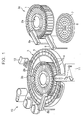
Fig. 1 is an exterior drawing of an automatic analyzer according to the first embodiment and the second embodiment. -
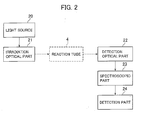
Fig. 2 is a block diagram showing the configuration of a photometric unit of the automatic analyzer according to the first embodiment and the second embodiment. -
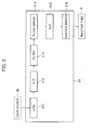
Fig. 3 is a block diagram showing the configuration of an irradiation optical part according to the first embodiment. -
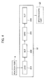
Fig. 4 is a block diagram showing the configuration of a detection optical part according to the first embodiment. -
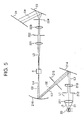
Fig. 5 is a diagram showing the optical system of the photometric unit according to the first embodiment. -
Fig. 6 is a diagram showing the effect according to the first embodiment. -
Fig. 7 is a diagram showing the effect according to the first embodiment. -
Fig. 8 is a diagram showing the effect according to a modified example of the first embodiment. -
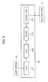
Fig. 9 is a block diagram showing the configuration of the irradiation optical part according to the second embodiment. -
Fig. 10 is a diagram showing the optical system of the photometric unit according to the second embodiment. - The analyzer according to the embodiments comprises an irradiation optical part that irradiates a mixture inside reaction tubes with light from a light source. Moreover, a detection optical part detects light transmitted through the mixture. Moreover, the irradiation optical part comprises a first optical element in which the light source is disposed at the front focal position and concentrates light from the light source. Moreover, a second optical element guides light transmitted through the first optical element to the reaction tubes. In addition, an incident numerical aperture adjustment member is provided at the rear side of the first optical element and adjusts the numerical aperture when light from the light source is incident into the reaction tubes.
- First, an explanation is provided regarding the configuration of the automatic analyzer common to both the first embodiment and the second embodiment with reference to
Fig. 1 . Note that the embodiments relate to the automatic analyzer; however, they are not limited to this. It is also possible to apply the configuration of the present embodiments to various spectroscopic analyzers. - The automatic analyzer comprises
reagent bottles 1,reagent racks 2a and 2b,reagent storages reaction tubes 4, a reaction disk 5, a test sample containers 6, a disk sampler 7, dispensingarms unit 10, aphotometric unit 11, and awashing unit 12. - The
reagent bottles 1 are containers in which reagents that react with various components of test samples are housed. Thereagent rack 2a is provided in thereagent storage 3a in a state in which the plurality ofreagent bottles 1 are housed. Similarly, the reagent rack 2b is provided in thereagent storage 3b in a state in which themultiple reagent bottles 1 are housed. - The
reaction tubes 4 are containers used when the test sample and the reagent are caused to react. Themultiple reaction tubes 4 are disposed at the circumference of the reaction disk 5. - The test sample containers 6 are containers in which test samples are stored. The multiple test sample containers 6 are disposed on top of the disk sampler 7.
- The reagents inside the
reagent bottles 1 are dispensed into thereaction tubes 4 by the dispensingarm 8a or the dispensingarm 8b. Moreover, the test samples inside the test sample containers 6 are dispensed into thereaction tubes 4 by the sampling arm 9. - The
reaction tubes 4 into which the test samples and the reagents are dispensed are moved to the position of the stirringunit 10 by the rotation of the reaction disk 5. The stirringunit 10 is a unit that stirs thereaction tubes 4 in which the test samples and the reagents are contained and mixes the test samples and the reagents. - The
stirred reaction tubes 4 are moved to the position of thephotometric unit 11. Thephotometric unit 11 is a unit that irradiates thereaction tubes 4 with light and measures changes in the absorbance, etc., of the mixture of the test sample and the reagent, in order to carry out component analysis of the test sample. - The
washing unit 12 is a unit that washes the inside of thereaction tubes 4 after the mixture inside thereaction tubes 4 is disposed of, upon completion of component analysis. - Next, with reference to
Fig. 2 , an explanation is provided regarding the configuration of thephotometric unit 11 which is common to both the first embodiment and the second embodiment. - The
photometric unit 11 comprises alight source 20, an irradiationoptical part 21, a detectionoptical part 22, aspectroscopic part 23, and adetection part 24. Note that in the embodiments, with respect to the optical element, etc. (which will be explained subsequently), disposed in the optical path of the irradiation optical part 21 (or the detection optical part 22), thelight source 20 side may be referred to as the "front side" and thedetection part 24 side may be referred to as the "rear side." - The
light source 20 has a function of generating light that is irradiated to thereaction tubes 4 through the irradiationoptical part 21. In the present embodiments, thelight source 20 is a white light source and in the measurement, light between the near-ultraviolet region (340 nm) and the near infrared (850 nm) is used. - The irradiation
optical part 21 is an optical system for guiding the light generated at thelight source 20 to thereaction tubes 4. Moreover, the detectionoptical part 22 is an optical system for guiding the light transmitted through thereaction tubes 4 to thespectroscopic part 23. The irradiationoptical part 21 and the detectionoptical part 22 will be explained in detail subsequently. - The
spectroscopic part 23 has a function of dividing light guided by the detectionoptical part 22 into spectra by each wavelength. Thespectroscopic part 23 includes spectroscopic optical elements such as diffraction grating. - The
detection part 24 has a function of detecting the intensity of the light that is divided into spectra by thespectroscopic part 23. Thedetection part 24 includes photodetectors such as PDAs (Photodiode Arrays). - The automatic analyzer according to the first embodiment is explained in detail with reference to
Fig. 3 to Fig. 7 . - As shown in
Fig. 3 , the irradiationoptical part 21 of thephotometric unit 11 in the first embodiment comprises a lens 211 (a first optical element), a slit 212 (a first slit), afilter 213, aplane mirror 214, a slit 215 (a second slit), and a concave mirror 216 (a second optical element). - The
lens 211 is disposed at the rear side of thelight source 20 and is an optical element for concentrating light from thelight source 20. Thelens 211 is made from an optical lens such as a convex lens. - The
slit 212 is disposed at the rear side of thelens 211 and is an aperture for limiting the luminous flux of the light from the lens 211 (light intensity adjustment). Theslit 212 may be a transmission type or it may be a reflection type. Moreover, instead of theslit 212, it is also possible to dispose a concave mirror or a plane mirror in order to adjust the luminous flux by means of the reflective effective diameter. In the present embodiment, this may be referred to as the "first slit," including the concave mirror or the plane mirror. - Here, in the present embodiment, the
light source 20 is disposed at the front focal position of thelens 211 and theslit 212 is disposed at the rear focal position of thelens 211. Consequently, the light from thelight source 20 is turned into light parallel to an optical axis O1 (refer toFig. 5 ) of thelight source 20 by thelens 211 and only part of this light passes through theslit 212. That is, by limiting some of the light among the light from thelight source 20, the size of the beam spot (which will be explained subsequently) and the intensity of light that is incident on thereaction tubes 4 are adjusted. - The
filter 213 is an infrared light cut filter that is disposed at the rear side of theslit 212 and absorbs the thermal components of the light passing through theslit 212. Note that the disposition of thefilter 213 is not limited to the rear side of theslit 212. For example, it may be provided between thelight source 20 and thelens 211. - The
plane mirror 214 is a mirror that is disposed at the rear side of thefilter 213 and reflects the light passing through theslit 212. In the present embodiment, the optical axis of the light reflected by theplane mirror 214 is referred to as an optical axis 02 (refer toFig. 5 ). By reflecting (turning back) the light using theplane mirror 214, it is possible to save space, compared to cases in which the irradiation optical system inside the irradiation optical part 21 (thelens 211, theslit 212, thefilter 213, theplane mirror 214, theslit 215, and the concave mirror 216) is disposed in a linear manner. - The
slit 215 is disposed at the rear side of theplane mirror 214 and is an aperture for adjusting the numerical aperture (hereinafter may be referred to as the "incident numerical aperture") when the light from thelight source 20 is incident into thereaction tube 4, by limiting the luminous flux of the light that is reflected by theplane mirror 214. That is, in the present embodiment, theslit 215 functions as the "incident numerical aperture adjustment member." - The
slit 215 may be a transmission type or a reflection type. Moreover, instead of theslit 215, it is also possible to dispose a concave mirror or a plane mirror and adjust the luminous flux by means of the reflective effective diameter. In the present embodiment, it may be referred to as the "second slit," including the concave mirror or the plane mirror. - Note that the
slit 215 may be disposed at the rear side of theconcave mirror 216. Alternatively, by integrally forming theslit 215 and theconcave mirror 216, one optical element may serve as theslit 215 and theconcave mirror 216. - The
concave mirror 216 is disposed at the rear side of theslit 215 and is an optical element for correcting chromatic aberrations of light passing through theslit 215 and for guiding the corrected light to thereaction tube 4. In the present embodiment, the reasons for using the concave mirror will be explained subsequently. - Moreover, as shown in
Fig. 4 , the detectionoptical part 22 of thephotometric unit 11 according to the first embodiment is constituted from a detection optical system comprising a lens 221 (a third optical element), a slit 222 (a third slit), a lens 223 (a fourth optical element), and a slit 224 (a fourth slit). - The
lens 221 is disposed at the rear side of thereaction tube 4 and is an optical element for collimating the light passing through thereaction tube 4. Thelens 221 is made from, for example, a collimating lens. The light passing through thereaction tube 4 is adjusted by thelens 221 so as to be in parallel with respect to an optical axis 03 (refer toFig. 5 ). - The
slit 222 is disposed at the rear side of thelens 221 and is an aperture for adjusting the numerical aperture (hereinafter may be referred to as a "detection numerical aperture") when the light passing through thereaction tube 4 is detected, by allowing some of the light that is collimated with thelens 221 to pass through. - The
lens 223 is disposed at the rear side of theslit 222 and is an optical element that concentrates the light passing through theslit 222 and guides it to theslit 224. Thelens 223 is made from an optical lens such as a convex lens. - The
slit 224 is disposed at the rear side of thelens 223 and is an aperture for allowing some of the light that is concentrated at thelens 223 to pass through. The light passing through theslit 224 is divided into spectra at thespectroscopic part 23 and is detected by thedetection part 24 by each wavelength component. - Next, an explanation is provided regarding how light progresses in the present embodiment with reference to
Fig. 5 . - Assuming that the
light source 20 is a point light source, light L0 generated by thelight source 20 that is disposed at the front focal position of thelens 211 is turned into light L1, which is parallel to the optical axis O1 of thelight source 20, by thelens 211. As the light L1 passes through theslit 212, it turns into light L2 in which the luminous flux of the L1 is partially limited. The light L2 is reflected by theplane mirror 214 after it passes through thefilter 213. The light L2 that is reflected by theplane mirror 214 reaches theslit 215. The light L2 reached theslit 215 turns into light L3 in which the luminous flux is partially limited, as it passes through thisslit 215. Accordingly, the light L3 reaches theconcave mirror 216. - Here, the angle at which the light L3 passing through the
slit 215 is incident on theconcave mirror 216 is preferably equal to or less than 10 degrees with respect to the reflectionoptical axis 03 of theconcave mirror 216. By changing the angle at which the light L3 passing through theslit 215 is incident on theconcave mirror 216, the state in which the image of light L4 reflected by theconcave mirror 216 is formed (imaging state) changes. -
Fig. 6 is a graph showing the intensity distribution at the cross-section of the diameter (the beam spot) of the light L4 that is incident on thereaction tube 4. The vertical axis indicates the intensity and the horizontal axis indicates the position at the cross-section of the beam spot. As is clear from the graph inFig. 6 , if the angle at which the light L3 passing through the slit 295 is incident on the concave mirror 216 (the angle of incidence) is equal to or less than 10 degrees with respect to the reflectionoptical axis 03 of theconcave mirror 216, the light L4 has uniform intensity distribution. Therefore, it is possible to realize an excellent imaging state because light of a uniform intensity can be irradiated to the test sample inside thereaction tube 4. - The light L4 that is reflected by the
concave mirror 216 is guided inside thereaction tube 4 and an image is formed inside thereaction tube 4. - Here, generally, when the image is formed using the lenses, there is a problem known as chromatic aberration in which a gap is caused to the imaging state as a result of the wavelength of the light. However, in the present embodiment, the chromatic aberration problem is solved using the
concave mirror 216 as the second optical element. -
Fig. 7 is a graph showing the results of a simulation of the degree of the chromatic aberration at the image forming position inside thereaction tube 4. The vertical axis indicates the intensity and the horizontal axis indicates the position at the cross-section of the beam spot. - As is clear from this graph, if the
concave mirror 216 is used as the second optical element, there is nearly constant intensity from the near-ultraviolet region (340 nm) to near infrared (850 nm). Consequently, it is possible to obtain a uniform imaging state because the chromatic aberration problem is not caused as a result of differences in the wavelengths. Moreover, it is possible to reduce spatial blurs or unevenness of the intensity using this type of light for measurement. - Note that the second optical element may be an element in which the chromatic aberration can be corrected. Therefore, instead of the
concave mirror 216, it is also possible to use, for example, an achromatic lens. - Light L5 passing through the
reaction tube 4 is collimated by thelens 221 and guided to thespectroscopic part 23 after passing through theslit 222, thelens 223, and theslit 224. - The light L5 reached the
spectroscopic part 23 is divided into spectra by each wavelength at thespectroscopic part 23 and detected by thedetection part 24 for each wavelength. The test sample is analyzed by calculating the absorbance or the permeability, based on the intensity of the detected light. - Note that reflected light is caused when the light that is divided into spectra at the
spectroscopic part 23 is incident on thedetection part 24. In order that the reflected light does not return to thespectroscopic part 23, the light incident surface of thedetection part 24 is disposed so as to be inclined with respect to anoptical axis 04 of the reflection surface of thespectroscopic part 23. - In the present embodiment, the second slit has a function of allowing some of the light passing through the first slit to pass through. That is, it is possible to adjust the incident numerical aperture by the second slit.
- Moreover, in the present embodiment, the third slit has a function of allowing some of the light passing through the
reaction tube 4 to pass through. That is, it is possible to adjust the detection numerical aperture by the third slit. - Moreover, in the present embodiment, if the second slit is integrally formed with the second optical element, it is possible to adjust the incident numerical aperture simply by disposing one optical element.
- In this way, according to the present embodiment, by adjusting the incident numerical aperture and the detection numerical aperture, it is possible to reduce the effect of scattered light by turbidimetric determination. Thereby, it is possible to carry out turbidimetric determination efficiently.
- Moreover, in the present embodiment, it is possible to prevent chromatic aberration using the
concave mirror 216 as the second optical element. Thereby, it is possible to carry out colorimetric determination and turbidimetric determination efficiently. - In the present modified example, the
slit 215 is provided with a variable mechanism (not shown in the figures) that makes it possible to change the width of this slit in order to adjust the incident numerical aperture. By providing this variable mechanism, it is possible to adjust the incident numerical aperture for each measurement item. - Moreover, as is the case with the
slit 215, it is possible to provide a variable mechanism to theslit 222 and adjust the detection numerical aperture for each measurement item. -
Fig. 8 is a graph of the test results showing the comparison results of performance of turbidimetric determination according to the incident numerical aperture (detection numerical aperture). InFig. 8 , the horizontal axis indicates the concentration of test substances and the vertical axis indicates the difference of light absorption detected by thedetection part 24. Moreover, inFig. 8 , the symbol A indicates cases in which the numerical aperture is 0.05. InFig. 8 , the symbol B indicates cases in which the numerical aperture is 0.10. InFig. 8 , C indicates cases in which the numerical aperture is 0.25. Note that inFig. 8 , it is assumed that the incident numerical aperture and the detection numerical aperture are equal. - Here, if the concentration of the test substance is calculated from the difference of light absorption, the difference of light absorption preferably retains a proportional relationship with respect to the concentration of the test substance.
- For example, in
Fig. 8 , consider cases of the difference of light absorption α. For cases of C (the numerical aperture 0.25), the concentration value of the test substance may be obtained from β to γ, making it impossible to accurately calculate test substance concentration. In contrast, if the numerical aperture is A (0.05), the test substance concentration is Δ. Therefore, it is possible to uniquely calculate the test substance concentration. - Moreover, the inclination of the graph is larger for cases in which the numerical aperture is A (0.05), compared to cases in which the numerical aperture is B (0.10). That is, the smaller the numerical aperture, the more accurately analysis can be carried out.
- Various effects can be obtained by adjusting the image location of the
concave mirror 216. For example, it is possible to reduce the amount of the mixture inside thereaction tube 4 by adjusting the positional relationship of theconcave mirror 216 and thereaction tube 4 such that the center of thereaction tube 4 is positioned at the image location of theconcave mirror 216. Alternatively, it is possible to reduce detection of the light that is scattered by a scatterer contained in the mixture inside thereaction tube 4 by adjusting the positional relationship of theconcave mirror 216 and thereaction tube 4 such that the image location of theconcave mirror 216 is positioned at the rear side with respect to the center of thereaction tubes 4. - Next, an explanation is provided regarding the second embodiment with reference to
Fig. 9 andFig. 10 . - As shown in
Fig. 9 , the irradiationoptical part 21 of thephotometric unit 11 according to the second embodiment comprises a lens 211 (a first optical element), a slit 212 (a first slit), afilter 213, and a convex lens 217 (a second optical element). - The
lens 211 is disposed at the rear side of thelight source 20 and is an optical element for concentrating the light from thelight source 20. Thelens 211 is made from, for example, an optical lens such as a convex lens. - The
slit 212 is disposed at the rear side of thelens 211 and is an aperture for limiting the luminous flux of the light from the lens 211 (incident numerical aperture adjustment). That is, in the present embodiment, theslit 212 functions as the "incident numerical aperture adjustment member." - The
slit 212 may be a transmission type or it may be a reflection type. Moreover, instead of theslit 212, it is also possible to dispose a concave mirror or a plane mirror in order to adjust the luminous flux be means of the reflective effective diameter. In the present embodiment, this may be referred to as the "first slit," including the concave mirror and/or the plane mirror. - Here, in the present embodiment, the
light source 20 is disposed at the front focal position of thelens 211 and theslit 212 is disposed at the rear focal position of thelens 211. Consequently, the light from thelight source 20 is turned into light parallel to an optical axis O1 (refer toFig. 10 ) of thelight source 20 by thelens 211, with only some of this light passing through theslit 212. That is, the incident numerical aperture is adjusted by limiting some of the light among the light from thelight source 20. - The
filter 213 is an infrared light cut filter that is disposed at the rear side of theslit 212 and absorbs the thermal components of the light passing through theslit 212. Note that the disposition of thefilter 213 is not limited to the rear side of theslit 212. For example, it may be provided between thelight source 20 and thelens 211. - The
convex lens 217 is disposed at the rear side of theslit 212 and is an optical element for guiding the light passing through theslit 212 to thereaction tubes 4. In the present embodiment, theconvex lens 217 operates as the second optical element. - Moreover, in the present embodiment, the
slit 212 is disposed at the front focal position of the convex lens 217 (at a position away from theconvex lens 217 by that focal distance). - As is the case with the first embodiment, the detection
optical part 22 is constituted from a detection optical system comprising a lens 221 (a third optical element), a slit 222 (a third slit), a lens 223 (a fourth optical element), and a slit 224 (a fourth slit). - The
lens 221 is disposed at the rear side of thereaction tube 4 and is an optical element for collimating the light passing through thereaction tube 4. Thelens 221 is made from, for example, a collimating lens. The light passing through thereaction tube 4 is adjusted by thelens 221 so as to be in parallel with respect to theoptical axis 05. - The
slit 222 is disposed at the rear side of thelens 221 and is an aperture for allowing some of the light that is collimated at thelens 221 to pass through (an aperture for adjusting the detection numerical aperture). - The
lens 223 is disposed at the rear side of theslit 222 and is an optical element that concentrates the light passing through theslit 222 and guides it to theslit 224. Thelens 223 is made from an optical lens such as a convex lens. - The
slit 224 is disposed at the rear side of thelens 223 and is an aperture for allowing some of the light that is concentrated at thelens 223 to pass through. The light passed through theslit 224 is divided into spectra at thespectroscopic part 23 and is detected by thedetection part 24 for each wavelength component. - Next, an explanation is provided regarding how light progresses in the present embodiment with reference to
Fig. 10 . - Light L6 generated by the
light source 20 disposed at the front side of thelens 211 is turned into light L7, which is parallel to theoptical axis 05 of thelight source 20, by thelens 211. As the light L7 passes through theslit 212, it turns into light L8 in which the luminous flux of the L7 is partially limited (in which the incident numerical aperture is adjusted). The light L8 reaches theconvex lens 217 after passing through thefilter 213. - Light L9 passed through the
convex lens 217 is incident on thereaction tube 4. - Light L10 passed through the
reaction tube 4 is collimated at thelens 221 and guided to thespectroscopic part 23 after going through theslit 222, thelens 223, and theslit 224. Note that light that is multi-scattered by a scattering medium inside thereaction tube 4 by setting the incident numerical aperture and the detection numerical aperture at the desired values rarely reaches thelens 221. - The light L10 reached the
spectroscopic part 23 is divided into spectra at thespectroscopic part 23 by each wavelength and is detected by thedetection part 24 for each wavelength. The test sample is analyzed by calculating the absorbance or the permeability, based on the intensity of the detected light. - Note that reflected light is caused when the light that is divided into spectra at the
spectroscopic part 23 is incident on thedetection part 24. In order that the reflected light does not return to thespectroscopic part 23, the light incident surface of thedetection part 24 is disposed so as to be inclined with respect to anoptical axis 06 of the reflection surface of thespectroscopic part 23. - As above, in the present embodiment, the incident numerical aperture is adjusted by the
slit 212 and the detection numerical aperture is adjusted by theslit 222. It is possible to reduce the detection of the light that is multi-scattered by a scattering medium inside thereaction tube 4 by setting the incident numerical aperture and the detection numerical aperture to desired values, making it possible to carry out turbidimetric determination efficiently. - Single-wavelength photometry that uses light of specific wavebands only, and two-wavelength photometry that uses light of two different wavebands and measures their relative changes are known photometric methods of the analyzer. According to the configuration of the first embodiment and the second embodiment, it is possible to efficiently carry out colorimetric determination and turbidimetric determination with either one of these photometric methods.
- In the above embodiments, it is also possible to dispose the outgoing radiation end of the fiber at the position in which the
light source 20 is disposed. In this case, the light source is provided as a separate body from thephotometric unit 11. By guiding the light from this light source through the fiber to inside the irradiationoptical part 21, it is possible to obtain the same photometry as the above embodiments. - While certain embodiments have been described, these embodiments have been presented by way of example only, and are not intended to limit the scope of the inventions. Indeed, the novel systems described herein may be embodied in a variety of their forms; furthermore, various omissions, substitutions and changes in the form of the systems described herein may be made without departing from the spirit of the inventions. The accompanying claims and their equivalents are intended to cover such forms or modifications as would fall within the scope and spirit of the inventions.
Claims (16)
- An analyzer comprising:an irradiation optical part that irradiates a mixture inside reaction tubes with light from a light source; anda detection optical part that detects light transmitted through said mixture,wherein said irradiation optical part comprises:a first optical element in which said light source is disposed at the front focal position and that concentrates light from said light source;a second optical element that guides light transmitted through said first optical element to said reaction tubes; andan incident numerical aperture adjustment member that is provided at the rear side of said first optical element and adjusts the numerical aperture when light from said light source is incident in said reaction tubes.
- The analyzer according to Claim 1, further comprising:a first slit that is disposed at the rear focal position of said first optical element and allows part of light transmitted through said first optical element to pass through, whereinsaid incident numerical aperture adjustment member is a second slit that allows part of light transmitted through said first slit to pass through.
- The analyzer according to Claim 2, wherein said second slit is disposed at the front focal position of said second optical element.
- The analyzer according to Claim 2, wherein said second slit is disposed between said second optical element and said reaction tubes.
- The analyzer according to Claim 2, wherein said second slit is integrally formed with said second optical element.
- The analyzer according to Claim 1, wherein said incident numerical aperture adjustment member is a first slit that is disposed at the rear focal position of said first optical element and allows part of light transmitted through said first optical element to pass through.
- The analyzer according to Claim 1, wherein said detection optical part comprises a member that is disposed at the rear side of said reaction tubes and adjusts the numerical aperture when detecting light transmitted through said reaction tubes.
- The analyzer according to Claim 1, said detection optical part comprising:a third optical element that collimates light transmitted through said reaction tubes;a third slit that allows part of light transmitted through said third optical element to pass through;a fourth optical element that concentrates light transmitted through said third slit; anda fourth slit that allows part of light concentrated by said fourth optical element to pass through;and comprising:a spectroscopic part that divides light transmitted through said fourth slit into spectra; anda detection part that detects light divided into spectra by said spectroscopic part.
- The analyzer according to Claim 7 wherein the numerical aperture when light from said light source is incident into said reaction tubes and the numerical aperture when light transmitted through said reaction tubes is detected in said detection part are equal.
- The analyzer according to Claim 8, wherein the numerical aperture when light from said light source is incident into said reaction tubes and the numerical aperture when light transmitted through said reaction tubes is detected in said detection part are equal.
- The analyzer according to Claim 7 wherein the numerical aperture when light from said light source is incident into said reaction tubes and the numerical aperture when light transmitted through said reaction tubes is detected by said detection part are both equal to or less than 0.1.
- The analyzer according to Claim 8, wherein the numerical aperture when light from said light source is incident into said reaction tubes and the numerical aperture when light transmitted through said reaction tubes is detected by said detection part are both equal to or less than 0.1.
- The analyzer according to Claim 11, wherein the numerical aperture when light from said light source is incident through said second optical element into said reaction tubes and the numerical aperture when light transmitted through said reaction tubes is detected by said detection part are both equal to or less than 0.05.
- The analyzer according to Claim 12, wherein the numerical aperture when light from said light source is incident through said second optical element into said reaction tubes and the numerical aperture when light transmitted through said reaction tubes is detected by said detection part are both equal to or less than 0.05.
- The analyzer according to Claim 1, wherein said second optical element is a concave mirror.
- The analyzer according to Claim 15, wherein the angle of incidence of light onto said concave mirror is equal to or less than 10 degrees.
Applications Claiming Priority (1)
| Application Number | Priority Date | Filing Date | Title |
|---|---|---|---|
| JP2011003622A JP5743558B2 (en) | 2011-01-12 | 2011-01-12 | Analysis equipment |
Publications (3)
| Publication Number | Publication Date |
|---|---|
| EP2477024A2 true EP2477024A2 (en) | 2012-07-18 |
| EP2477024A3 EP2477024A3 (en) | 2012-11-14 |
| EP2477024B1 EP2477024B1 (en) | 2017-11-08 |
Family
ID=45571366
Family Applications (1)
| Application Number | Title | Priority Date | Filing Date |
|---|---|---|---|
| EP12150820.4A Not-in-force EP2477024B1 (en) | 2011-01-12 | 2012-01-11 | Analyzer |
Country Status (4)
| Country | Link |
|---|---|
| US (1) | US9651478B2 (en) |
| EP (1) | EP2477024B1 (en) |
| JP (1) | JP5743558B2 (en) |
| CN (1) | CN102590106B (en) |
Families Citing this family (8)
| Publication number | Priority date | Publication date | Assignee | Title |
|---|---|---|---|---|
| AU2014348910B2 (en) * | 2013-11-13 | 2017-04-20 | Becton, Dickinson And Company | Optical imaging system and methods for using the same |
| KR102161058B1 (en) * | 2013-12-24 | 2020-09-29 | 삼성전자주식회사 | Optical detection apparatus and method of compensating detection error |
| KR20150102180A (en) * | 2014-02-27 | 2015-09-07 | 삼성디스플레이 주식회사 | Laser beam irradiation apparatus and manufacturing method of organic light emitting display apparatus using the same |
| FR3035716B1 (en) * | 2015-04-30 | 2019-06-21 | Biomerieux | MACHINE AND METHOD FOR AUTOMATED IN VITRO DETECTION OF ANALYTES USING CHROMATIC SPECTRAL DECOMPOSITION OF AN OPTICAL RESPONSE |
| JP6637407B2 (en) * | 2016-12-27 | 2020-01-29 | 株式会社日立ハイテクノロジーズ | Automatic analyzer |
| WO2018140698A1 (en) * | 2017-01-27 | 2018-08-02 | Tedia Company, Inc. | Chemical reagent bottle internally coated with a fluoropolymer |
| JP6466496B2 (en) * | 2017-04-05 | 2019-02-06 | Ckd株式会社 | Inspection apparatus, PTP packaging machine, and PTP sheet manufacturing method |
| CN107907504B (en) * | 2017-10-28 | 2020-04-14 | 东台市凯润精密机械股份有限公司 | A filter lens for ambient air turbidity detector |
Family Cites Families (35)
| Publication number | Priority date | Publication date | Assignee | Title |
|---|---|---|---|---|
| US3924925A (en) * | 1974-01-30 | 1975-12-09 | Rca Corp | Focussed image hologram projector using a long narrow light source |
| US3981562A (en) * | 1974-09-09 | 1976-09-21 | Optical Coating Laboratory, Inc. | Spatial filtering for error detection |
| CA1228748A (en) * | 1983-12-24 | 1987-11-03 | Hans Oetliker | Method and apparatus for guiding and collecting light in photometry or the like |
| JPS64451A (en) * | 1987-02-20 | 1989-01-05 | Nittec Co Ltd | Method and instrument for optical measurement with automatic analysis device |
| JPH01145552A (en) * | 1987-12-02 | 1989-06-07 | Olympus Optical Co Ltd | automatic analyzer |
| US5157454A (en) | 1989-11-30 | 1992-10-20 | Otsuka Electronics Co., Ltd. | Differential refractometer |
| JPH03235042A (en) * | 1990-02-13 | 1991-10-21 | Hitachi Ltd | Automatic analyzer |
| JPH0438555A (en) | 1990-06-04 | 1992-02-07 | Nec Corp | System for communication between processors |
| JP2948405B2 (en) * | 1992-03-03 | 1999-09-13 | 三菱重工業株式会社 | Quick method for measuring microorganisms |
| JP2936947B2 (en) * | 1993-03-22 | 1999-08-23 | 株式会社日立製作所 | Spectrofluorometer |
| JPH06319594A (en) * | 1993-05-07 | 1994-11-22 | Mitsubishi Heavy Ind Ltd | Determination of bio-activity |
| JPH06341944A (en) | 1993-06-01 | 1994-12-13 | Saika Gijutsu Kenkyusho | Light source of measuring machine |
| US5717605A (en) * | 1993-10-14 | 1998-02-10 | Olympus Optical Co., Ltd. | Color classification apparatus |
| JPH07128239A (en) * | 1993-10-29 | 1995-05-19 | Shimadzu Corp | Photoexcitation device for cadide compounds |
| US5506679A (en) | 1994-09-08 | 1996-04-09 | Hach Company | Nephelometer instrument |
| JPH0989763A (en) | 1995-09-20 | 1997-04-04 | Hitachi Ltd | Atomic absorption spectrophotometer |
| ATE226722T1 (en) | 1995-11-30 | 2002-11-15 | Thermo Labsystems Oy | NEPHELOMETER |
| JP3225484B2 (en) * | 1997-12-18 | 2001-11-05 | 廣幸 小川 | Microbial testing method, microbial count testing method, microbial testing tool, microbial testing device, and microbial propagation time measuring device |
| JPH11295219A (en) | 1998-04-13 | 1999-10-29 | Hitachi Ltd | Spectrophotometer and automatic analyzer using it |
| JP2000180368A (en) | 1998-12-16 | 2000-06-30 | Hitachi Ltd | Chemical analyzer |
| JP4334098B2 (en) | 1999-12-27 | 2009-09-16 | 株式会社東芝 | Automatic analyzer |
| JP2001235422A (en) * | 2000-02-22 | 2001-08-31 | Toshiba Corp | Automatic analyzer |
| JP2003149157A (en) * | 2001-11-09 | 2003-05-21 | Toshiba Corp | Chemical analyzer |
| JP2005049109A (en) | 2003-07-29 | 2005-02-24 | Toshiba Corp | Chemical analyzer |
| JP2005291726A (en) * | 2004-03-31 | 2005-10-20 | Fujifilm Techno Products Co Ltd | Biochemical analyzer |
| EP1751523B1 (en) * | 2004-05-13 | 2017-10-04 | NarTest AS | A portable device and method for on-site detection and quantification of drugs |
| CN100451611C (en) | 2005-10-21 | 2009-01-14 | 中国科学院上海光学精密机械研究所 | Spectrophotometer for quickly measuring spectrum |
| US7538874B2 (en) | 2006-03-23 | 2009-05-26 | Hach Company | Measurement of light from a predefined scatter angle from particulate matter in a media |
| JP4750052B2 (en) * | 2007-02-07 | 2011-08-17 | パナソニック株式会社 | Measuring method using biosensor |
| JP2009009760A (en) | 2007-06-26 | 2009-01-15 | Toshiba Lighting & Technology Corp | Lighting device |
| JP5260903B2 (en) | 2007-07-06 | 2013-08-14 | 株式会社東芝 | Automatic analyzer |
| WO2009028064A1 (en) * | 2007-08-30 | 2009-03-05 | Shimadzu Corporation | Spectrophotometer |
| JP2008051822A (en) * | 2007-10-09 | 2008-03-06 | Toshiba Corp | Chemical analyzer |
| JP5350810B2 (en) * | 2008-01-11 | 2013-11-27 | 株式会社東芝 | Automatic analyzer and automatic analysis method |
| JP5348899B2 (en) | 2008-01-30 | 2013-11-20 | カヤバ工業株式会社 | Brake system |
-
2011
- 2011-01-12 JP JP2011003622A patent/JP5743558B2/en active Active
-
2012
- 2012-01-10 US US13/347,172 patent/US9651478B2/en not_active Expired - Fee Related
- 2012-01-11 CN CN201210006886.1A patent/CN102590106B/en not_active Expired - Fee Related
- 2012-01-11 EP EP12150820.4A patent/EP2477024B1/en not_active Not-in-force
Non-Patent Citations (1)
| Title |
|---|
| None |
Also Published As
| Publication number | Publication date |
|---|---|
| CN102590106B (en) | 2014-11-05 |
| JP2012145429A (en) | 2012-08-02 |
| JP5743558B2 (en) | 2015-07-01 |
| US20120177538A1 (en) | 2012-07-12 |
| US9651478B2 (en) | 2017-05-16 |
| EP2477024B1 (en) | 2017-11-08 |
| EP2477024A3 (en) | 2012-11-14 |
| CN102590106A (en) | 2012-07-18 |
Similar Documents
| Publication | Publication Date | Title |
|---|---|---|
| EP2477024B1 (en) | Analyzer | |
| US9448161B2 (en) | Optical device, particularly a polarimeter, for detecting inhomogeneities in a sample | |
| US9383311B2 (en) | Non-scanning SPR system | |
| CN102308199A (en) | Sample analyzing apparatus | |
| EP2466292B1 (en) | System for performing scattering and absorbance assays | |
| CN107533007B (en) | Machine and method for automated in vitro analyte detection via color spectral decomposition of optical responses | |
| EP1992936B1 (en) | Analyzing apparatus | |
| EP0771417B1 (en) | Determination of light absorption pathlength in a vertical-beam photometer | |
| US20260104290A1 (en) | Absorbance spectroscopy analyzer and method of use | |
| JP2008051822A (en) | Chemical analyzer | |
| US20070030482A1 (en) | Spectrophotometer with adjustable light pathlength | |
| KR100961138B1 (en) | Spectrometer | |
| KR20190032268A (en) | Optical measuring device | |
| JP2007127449A (en) | Measuring container | |
| US20250341462A1 (en) | Dissolution analyzer for monitoring or analyzing substance dissolution into a liquid or liquid matrix, and dissolution analysis method | |
| JP5017444B2 (en) | Chemical analyzer | |
| JP2015175667A (en) | Automatic analysis apparatus | |
| JP2007218882A (en) | Autoanalyzer and spectroscopic device | |
| JP2007127448A (en) | Analyzing optical device |
Legal Events
| Date | Code | Title | Description |
|---|---|---|---|
| PUAI | Public reference made under article 153(3) epc to a published international application that has entered the european phase |
Free format text: ORIGINAL CODE: 0009012 |
|
| 17P | Request for examination filed |
Effective date: 20120111 |
|
| AK | Designated contracting states |
Kind code of ref document: A2 Designated state(s): AL AT BE BG CH CY CZ DE DK EE ES FI FR GB GR HR HU IE IS IT LI LT LU LV MC MK MT NL NO PL PT RO RS SE SI SK SM TR |
|
| AX | Request for extension of the european patent |
Extension state: BA ME |
|
| PUAL | Search report despatched |
Free format text: ORIGINAL CODE: 0009013 |
|
| AK | Designated contracting states |
Kind code of ref document: A3 Designated state(s): AL AT BE BG CH CY CZ DE DK EE ES FI FR GB GR HR HU IE IS IT LI LT LU LV MC MK MT NL NO PL PT RO RS SE SI SK SM TR |
|
| AX | Request for extension of the european patent |
Extension state: BA ME |
|
| RIC1 | Information provided on ipc code assigned before grant |
Ipc: G01N 35/02 20060101ALI20121010BHEP Ipc: G01N 21/25 20060101AFI20121010BHEP |
|
| RAP1 | Party data changed (applicant data changed or rights of an application transferred) |
Owner name: TOSHIBA MEDICAL SYSTEMS CORPORATION |
|
| 17Q | First examination report despatched |
Effective date: 20160627 |
|
| STAA | Information on the status of an ep patent application or granted ep patent |
Free format text: STATUS: EXAMINATION IS IN PROGRESS |
|
| REG | Reference to a national code |
Ref country code: DE Ref legal event code: R079 Ref document number: 602012039406 Country of ref document: DE Free format text: PREVIOUS MAIN CLASS: G01N0021250000 Ipc: G01J0003360000 |
|
| GRAP | Despatch of communication of intention to grant a patent |
Free format text: ORIGINAL CODE: EPIDOSNIGR1 |
|
| RIC1 | Information provided on ipc code assigned before grant |
Ipc: G01N 21/03 20060101ALI20170407BHEP Ipc: G01N 30/74 20060101ALI20170407BHEP Ipc: G01N 21/25 20060101ALI20170407BHEP Ipc: G01N 35/02 20060101ALI20170407BHEP Ipc: G01N 3/04 20060101ALI20170407BHEP Ipc: G01J 3/36 20060101AFI20170407BHEP Ipc: G01N 3/00 20060101ALI20170407BHEP |
|
| STAA | Information on the status of an ep patent application or granted ep patent |
Free format text: STATUS: GRANT OF PATENT IS INTENDED |
|
| INTG | Intention to grant announced |
Effective date: 20170518 |
|
| GRAS | Grant fee paid |
Free format text: ORIGINAL CODE: EPIDOSNIGR3 |
|
| GRAA | (expected) grant |
Free format text: ORIGINAL CODE: 0009210 |
|
| STAA | Information on the status of an ep patent application or granted ep patent |
Free format text: STATUS: THE PATENT HAS BEEN GRANTED |
|
| AK | Designated contracting states |
Kind code of ref document: B1 Designated state(s): AL AT BE BG CH CY CZ DE DK EE ES FI FR GB GR HR HU IE IS IT LI LT LU LV MC MK MT NL NO PL PT RO RS SE SI SK SM TR |
|
| REG | Reference to a national code |
Ref country code: GB Ref legal event code: FG4D |
|
| REG | Reference to a national code |
Ref country code: CH Ref legal event code: EP Ref country code: AT Ref legal event code: REF Ref document number: 944582 Country of ref document: AT Kind code of ref document: T Effective date: 20171115 |
|
| REG | Reference to a national code |
Ref country code: IE Ref legal event code: FG4D |
|
| REG | Reference to a national code |
Ref country code: DE Ref legal event code: R096 Ref document number: 602012039406 Country of ref document: DE |
|
| REG | Reference to a national code |
Ref country code: NL Ref legal event code: MP Effective date: 20171108 |
|
| REG | Reference to a national code |
Ref country code: LT Ref legal event code: MG4D |
|
| REG | Reference to a national code |
Ref country code: AT Ref legal event code: MK05 Ref document number: 944582 Country of ref document: AT Kind code of ref document: T Effective date: 20171108 |
|
| PG25 | Lapsed in a contracting state [announced via postgrant information from national office to epo] |
Ref country code: NL Free format text: LAPSE BECAUSE OF FAILURE TO SUBMIT A TRANSLATION OF THE DESCRIPTION OR TO PAY THE FEE WITHIN THE PRESCRIBED TIME-LIMIT Effective date: 20171108 Ref country code: SE Free format text: LAPSE BECAUSE OF FAILURE TO SUBMIT A TRANSLATION OF THE DESCRIPTION OR TO PAY THE FEE WITHIN THE PRESCRIBED TIME-LIMIT Effective date: 20171108 Ref country code: FI Free format text: LAPSE BECAUSE OF FAILURE TO SUBMIT A TRANSLATION OF THE DESCRIPTION OR TO PAY THE FEE WITHIN THE PRESCRIBED TIME-LIMIT Effective date: 20171108 Ref country code: NO Free format text: LAPSE BECAUSE OF FAILURE TO SUBMIT A TRANSLATION OF THE DESCRIPTION OR TO PAY THE FEE WITHIN THE PRESCRIBED TIME-LIMIT Effective date: 20180208 Ref country code: LT Free format text: LAPSE BECAUSE OF FAILURE TO SUBMIT A TRANSLATION OF THE DESCRIPTION OR TO PAY THE FEE WITHIN THE PRESCRIBED TIME-LIMIT Effective date: 20171108 Ref country code: ES Free format text: LAPSE BECAUSE OF FAILURE TO SUBMIT A TRANSLATION OF THE DESCRIPTION OR TO PAY THE FEE WITHIN THE PRESCRIBED TIME-LIMIT Effective date: 20171108 |
|
| PG25 | Lapsed in a contracting state [announced via postgrant information from national office to epo] |
Ref country code: AT Free format text: LAPSE BECAUSE OF FAILURE TO SUBMIT A TRANSLATION OF THE DESCRIPTION OR TO PAY THE FEE WITHIN THE PRESCRIBED TIME-LIMIT Effective date: 20171108 Ref country code: RS Free format text: LAPSE BECAUSE OF FAILURE TO SUBMIT A TRANSLATION OF THE DESCRIPTION OR TO PAY THE FEE WITHIN THE PRESCRIBED TIME-LIMIT Effective date: 20171108 Ref country code: GR Free format text: LAPSE BECAUSE OF FAILURE TO SUBMIT A TRANSLATION OF THE DESCRIPTION OR TO PAY THE FEE WITHIN THE PRESCRIBED TIME-LIMIT Effective date: 20180209 Ref country code: HR Free format text: LAPSE BECAUSE OF FAILURE TO SUBMIT A TRANSLATION OF THE DESCRIPTION OR TO PAY THE FEE WITHIN THE PRESCRIBED TIME-LIMIT Effective date: 20171108 Ref country code: BG Free format text: LAPSE BECAUSE OF FAILURE TO SUBMIT A TRANSLATION OF THE DESCRIPTION OR TO PAY THE FEE WITHIN THE PRESCRIBED TIME-LIMIT Effective date: 20180208 Ref country code: IS Free format text: LAPSE BECAUSE OF FAILURE TO SUBMIT A TRANSLATION OF THE DESCRIPTION OR TO PAY THE FEE WITHIN THE PRESCRIBED TIME-LIMIT Effective date: 20180308 Ref country code: LV Free format text: LAPSE BECAUSE OF FAILURE TO SUBMIT A TRANSLATION OF THE DESCRIPTION OR TO PAY THE FEE WITHIN THE PRESCRIBED TIME-LIMIT Effective date: 20171108 |
|
| PG25 | Lapsed in a contracting state [announced via postgrant information from national office to epo] |
Ref country code: CZ Free format text: LAPSE BECAUSE OF FAILURE TO SUBMIT A TRANSLATION OF THE DESCRIPTION OR TO PAY THE FEE WITHIN THE PRESCRIBED TIME-LIMIT Effective date: 20171108 Ref country code: SK Free format text: LAPSE BECAUSE OF FAILURE TO SUBMIT A TRANSLATION OF THE DESCRIPTION OR TO PAY THE FEE WITHIN THE PRESCRIBED TIME-LIMIT Effective date: 20171108 Ref country code: DK Free format text: LAPSE BECAUSE OF FAILURE TO SUBMIT A TRANSLATION OF THE DESCRIPTION OR TO PAY THE FEE WITHIN THE PRESCRIBED TIME-LIMIT Effective date: 20171108 Ref country code: EE Free format text: LAPSE BECAUSE OF FAILURE TO SUBMIT A TRANSLATION OF THE DESCRIPTION OR TO PAY THE FEE WITHIN THE PRESCRIBED TIME-LIMIT Effective date: 20171108 Ref country code: CY Free format text: LAPSE BECAUSE OF FAILURE TO SUBMIT A TRANSLATION OF THE DESCRIPTION OR TO PAY THE FEE WITHIN THE PRESCRIBED TIME-LIMIT Effective date: 20171108 |
|
| REG | Reference to a national code |
Ref country code: DE Ref legal event code: R097 Ref document number: 602012039406 Country of ref document: DE |
|
| PG25 | Lapsed in a contracting state [announced via postgrant information from national office to epo] |
Ref country code: IT Free format text: LAPSE BECAUSE OF FAILURE TO SUBMIT A TRANSLATION OF THE DESCRIPTION OR TO PAY THE FEE WITHIN THE PRESCRIBED TIME-LIMIT Effective date: 20171108 Ref country code: PL Free format text: LAPSE BECAUSE OF FAILURE TO SUBMIT A TRANSLATION OF THE DESCRIPTION OR TO PAY THE FEE WITHIN THE PRESCRIBED TIME-LIMIT Effective date: 20171108 Ref country code: SM Free format text: LAPSE BECAUSE OF FAILURE TO SUBMIT A TRANSLATION OF THE DESCRIPTION OR TO PAY THE FEE WITHIN THE PRESCRIBED TIME-LIMIT Effective date: 20171108 Ref country code: RO Free format text: LAPSE BECAUSE OF FAILURE TO SUBMIT A TRANSLATION OF THE DESCRIPTION OR TO PAY THE FEE WITHIN THE PRESCRIBED TIME-LIMIT Effective date: 20171108 |
|
| REG | Reference to a national code |
Ref country code: CH Ref legal event code: PL |
|
| PLBE | No opposition filed within time limit |
Free format text: ORIGINAL CODE: 0009261 |
|
| STAA | Information on the status of an ep patent application or granted ep patent |
Free format text: STATUS: NO OPPOSITION FILED WITHIN TIME LIMIT |
|
| 26N | No opposition filed |
Effective date: 20180809 |
|
| GBPC | Gb: european patent ceased through non-payment of renewal fee |
Effective date: 20180208 |
|
| PG25 | Lapsed in a contracting state [announced via postgrant information from national office to epo] |
Ref country code: LU Free format text: LAPSE BECAUSE OF NON-PAYMENT OF DUE FEES Effective date: 20180111 Ref country code: FR Free format text: LAPSE BECAUSE OF NON-PAYMENT OF DUE FEES Effective date: 20180131 |
|
| REG | Reference to a national code |
Ref country code: IE Ref legal event code: MM4A |
|
| REG | Reference to a national code |
Ref country code: FR Ref legal event code: ST Effective date: 20180928 |
|
| REG | Reference to a national code |
Ref country code: BE Ref legal event code: MM Effective date: 20180131 |
|
| PG25 | Lapsed in a contracting state [announced via postgrant information from national office to epo] |
Ref country code: LI Free format text: LAPSE BECAUSE OF NON-PAYMENT OF DUE FEES Effective date: 20180131 Ref country code: SI Free format text: LAPSE BECAUSE OF FAILURE TO SUBMIT A TRANSLATION OF THE DESCRIPTION OR TO PAY THE FEE WITHIN THE PRESCRIBED TIME-LIMIT Effective date: 20171108 Ref country code: BE Free format text: LAPSE BECAUSE OF NON-PAYMENT OF DUE FEES Effective date: 20180131 Ref country code: CH Free format text: LAPSE BECAUSE OF NON-PAYMENT OF DUE FEES Effective date: 20180131 |
|
| PG25 | Lapsed in a contracting state [announced via postgrant information from national office to epo] |
Ref country code: IE Free format text: LAPSE BECAUSE OF NON-PAYMENT OF DUE FEES Effective date: 20180111 |
|
| PG25 | Lapsed in a contracting state [announced via postgrant information from national office to epo] |
Ref country code: GB Free format text: LAPSE BECAUSE OF NON-PAYMENT OF DUE FEES Effective date: 20180208 |
|
| PG25 | Lapsed in a contracting state [announced via postgrant information from national office to epo] |
Ref country code: MC Free format text: LAPSE BECAUSE OF FAILURE TO SUBMIT A TRANSLATION OF THE DESCRIPTION OR TO PAY THE FEE WITHIN THE PRESCRIBED TIME-LIMIT Effective date: 20171108 |
|
| PG25 | Lapsed in a contracting state [announced via postgrant information from national office to epo] |
Ref country code: MT Free format text: LAPSE BECAUSE OF NON-PAYMENT OF DUE FEES Effective date: 20180111 |
|
| PG25 | Lapsed in a contracting state [announced via postgrant information from national office to epo] |
Ref country code: TR Free format text: LAPSE BECAUSE OF FAILURE TO SUBMIT A TRANSLATION OF THE DESCRIPTION OR TO PAY THE FEE WITHIN THE PRESCRIBED TIME-LIMIT Effective date: 20171108 |
|
| PG25 | Lapsed in a contracting state [announced via postgrant information from national office to epo] |
Ref country code: HU Free format text: LAPSE BECAUSE OF FAILURE TO SUBMIT A TRANSLATION OF THE DESCRIPTION OR TO PAY THE FEE WITHIN THE PRESCRIBED TIME-LIMIT; INVALID AB INITIO Effective date: 20120111 Ref country code: PT Free format text: LAPSE BECAUSE OF FAILURE TO SUBMIT A TRANSLATION OF THE DESCRIPTION OR TO PAY THE FEE WITHIN THE PRESCRIBED TIME-LIMIT Effective date: 20171108 |
|
| PG25 | Lapsed in a contracting state [announced via postgrant information from national office to epo] |
Ref country code: MK Free format text: LAPSE BECAUSE OF NON-PAYMENT OF DUE FEES Effective date: 20171108 |
|
| PG25 | Lapsed in a contracting state [announced via postgrant information from national office to epo] |
Ref country code: AL Free format text: LAPSE BECAUSE OF FAILURE TO SUBMIT A TRANSLATION OF THE DESCRIPTION OR TO PAY THE FEE WITHIN THE PRESCRIBED TIME-LIMIT Effective date: 20171108 |
|
| PGFP | Annual fee paid to national office [announced via postgrant information from national office to epo] |
Ref country code: DE Payment date: 20231121 Year of fee payment: 13 |
|
| REG | Reference to a national code |
Ref country code: DE Ref legal event code: R119 Ref document number: 602012039406 Country of ref document: DE |
|
| PG25 | Lapsed in a contracting state [announced via postgrant information from national office to epo] |
Ref country code: DE Free format text: LAPSE BECAUSE OF NON-PAYMENT OF DUE FEES Effective date: 20250801 |