EP2477003A1 - Rotation angle detecting device - Google Patents
Rotation angle detecting device Download PDFInfo
- Publication number
- EP2477003A1 EP2477003A1 EP12150150A EP12150150A EP2477003A1 EP 2477003 A1 EP2477003 A1 EP 2477003A1 EP 12150150 A EP12150150 A EP 12150150A EP 12150150 A EP12150150 A EP 12150150A EP 2477003 A1 EP2477003 A1 EP 2477003A1
- Authority
- EP
- European Patent Office
- Prior art keywords
- rotation angle
- magnetic
- magnetic pole
- pole
- rotor
- Prior art date
- Legal status (The legal status is an assumption and is not a legal conclusion. Google has not performed a legal analysis and makes no representation as to the accuracy of the status listed.)
- Granted
Links
- 230000007704 transition Effects 0.000 claims abstract description 97
- 238000001514 detection method Methods 0.000 claims description 9
- 238000000034 method Methods 0.000 description 52
- 230000008569 process Effects 0.000 description 42
- 230000005856 abnormality Effects 0.000 description 30
- 230000002159 abnormal effect Effects 0.000 description 8
- 230000015654 memory Effects 0.000 description 3
- 230000007423 decrease Effects 0.000 description 2
- 230000006870 function Effects 0.000 description 2
- 230000008859 change Effects 0.000 description 1
- 230000007257 malfunction Effects 0.000 description 1
Images




Classifications
-
- G—PHYSICS
- G01—MEASURING; TESTING
- G01D—MEASURING NOT SPECIALLY ADAPTED FOR A SPECIFIC VARIABLE; ARRANGEMENTS FOR MEASURING TWO OR MORE VARIABLES NOT COVERED IN A SINGLE OTHER SUBCLASS; TARIFF METERING APPARATUS; MEASURING OR TESTING NOT OTHERWISE PROVIDED FOR
- G01D5/00—Mechanical means for transferring the output of a sensing member; Means for converting the output of a sensing member to another variable where the form or nature of the sensing member does not constrain the means for converting; Transducers not specially adapted for a specific variable
- G01D5/12—Mechanical means for transferring the output of a sensing member; Means for converting the output of a sensing member to another variable where the form or nature of the sensing member does not constrain the means for converting; Transducers not specially adapted for a specific variable using electric or magnetic means
- G01D5/14—Mechanical means for transferring the output of a sensing member; Means for converting the output of a sensing member to another variable where the form or nature of the sensing member does not constrain the means for converting; Transducers not specially adapted for a specific variable using electric or magnetic means influencing the magnitude of a current or voltage
- G01D5/142—Mechanical means for transferring the output of a sensing member; Means for converting the output of a sensing member to another variable where the form or nature of the sensing member does not constrain the means for converting; Transducers not specially adapted for a specific variable using electric or magnetic means influencing the magnitude of a current or voltage using Hall-effect devices
- G01D5/145—Mechanical means for transferring the output of a sensing member; Means for converting the output of a sensing member to another variable where the form or nature of the sensing member does not constrain the means for converting; Transducers not specially adapted for a specific variable using electric or magnetic means influencing the magnitude of a current or voltage using Hall-effect devices influenced by the relative movement between the Hall device and magnetic fields
Definitions
- the invention relates to a rotation angle detecting device that detects the rotation angle of a rotor, for example, a rotor of a brushless motor.
- a rotation angle detecting device that detects the rotation angle of the rotor of the brushless motor using a detection rotor that rotates in accordance with rotation of the brushless motor.
- a detection rotor 101 (hereinafter, referred to as "rotor 101") has a cylindrical magnet 102 with a plurality of magnetic pole pairs. The number of magnetic pole pairs of the cylindrical magnet 102 corresponds to the number of magnetic pole pairs of the rotor of the brushless motor.
- Two magnetic sensors 121 and 122 are arranged around the rotor 101 at a predetermined angular interval about the rotation axis of the rotor 101.
- the magnetic sensors 121 and 122 output respective sinusoidal signals that have a phase difference of a given degree.
- the rotation angle of the rotor 101 (the rotation angle of the rotor of the brushless motor) is detected on the basis of these two sinusoidal signals (for example, see Japanese Patent Application Publication No. 2003-241411 ( JP-A-2003-241411 ) and Japanese Patent Application Publication No. 2002-213944 ( JP-A-2002-213944 )).
- the magnet 102 has the five magnetic pole pairs (M0, M1), (M2, M3), (M4, M5), (M6, M7) and (M8, M9). That is, the magnet 102 has ten magnetic poles M0 to M9 that are arranged at equiangular intervals.
- the magnetic poles M0 to M9 are arranged at angular intervals of 36° (180° in electric angle) about the rotation axis of the rotor 101.
- the two magnetic sensors 121 and 122 are arranged at an angular interval of 18° (90° in electric angle) about the rotation axis of the rotor 101.
- the direction indicated by the arrow in FIG. 8 is defined as the normal rotation direction of the detection rotor 101. Then, as the rotor 101 is rotated in the normal direction, the rotation angle of the rotor 101 increases, while, as the rotor 101 is rotated in the reverse direction, the rotation angle of the rotor 101 decreases. As shown in FIG. 9 , the magnetic sensors 121 and 122 respectively output sinusoidal signals V1 and V2. Each of the sinusoidal signals V1 and V2 has a cycle, during which the rotor 101 rotates by an angle (72° (360° in electric angle)) corresponding to a single magnetic pole pair, as one cycle.
- the angular range of one rotation of the rotor 101 is divided into five sections that correspond to the five magnetic pole pairs, and then the angle of the rotor 101, which is expressed on the condition that the start position of each section is 0° and the end position of each section is 360°, is termed the electric angle ⁇ e of the rotor 101.
- the angular widths of the ten magnetic poles are equal to one another, so the electric angle ⁇ e of the rotor 101 coincides with the electric angle of the rotor of the brushless motor.
- A1 and A2 are amplitudes. If the amplitude A1 of the output signal V1 and the amplitude A2 of the output signal V2 are equal to each other, the electric angle ⁇ e of the rotor 101 may be obtained using both output signals V1 and V2 according to Expression 1 shown below.
- a steering angle or the angular velocity of a steering angle may be used to control the brushless motor.
- the steering angle and the angular velocity of the steering angle may be computed on the basis of the mechanical angle of the rotor of the brushless motor.
- the angular velocity of the steering angle may be computed on the basis of the mechanical angle (hereinafter, referred to as "relative mechanical angle") of the rotor with respect to the initial position of the rotor at the time of the start of rotation angle computing process.
- detecting a magnetic pole transition in the output signal of the magnetic sensor is detecting a transition in magnetic pole sensed by the magnetic sensor and the direction of the transition in magnetic pole.
- a magnetic pole transition in the output signal of the magnetic sensor may be detected, for example, on the basis of the output signals V1 and V2 of the two respective magnetic sensors 121 and 122 shown in FIG. 8 .
- FIG. 9 shows the output signals V1 and V2 of the magnetic sensors 121 and 122 with respect to a rotor angle (mechanical angle) in the case where the rotation angle of the rotor 101 is set at 0° when the boundary between the magnetic pole M9 and magnetic pole M0 of the rotor 101 faces the first magnetic sensor 121.
- the rotor angle is expressed by an angle that is obtained by multiplying an actual mechanical angle by the number of magnetic pole pairs ("5" in this example) of the rotor 101.
- the magnetic poles M0 to M9 each indicate the magnetic pole that is sensed by the first magnetic sensor 121.
- a transition in magnetic pole sensed by the first magnetic sensor 121 is classified into the following four cases.
- the transition in magnetic pole in the above description a) may be detected by determining whether the following first determination condition is satisfied.
- First Determination Condition "V2 ⁇ 0" and "immediately preceding value of V1 > 0" and "current value of V1 ⁇ 0"
- the transition in magnetic pole in the above description b) (see Qb in FIG. 9 ) may be detected by determining whether the following second determination condition is satisfied.
- Second Determination Condition "V2 > 0" and “immediately preceding value of V1 ⁇ 0" and “current value of V1 ⁇ 0"
- the transition in magnetic pole in the above description c) (see Qc in FIG. 9 ) may be detected by determining whether the following third determination condition is satisfied.
- Third Determination Condition "V2 > 0" and “immediately preceding value of V1 ⁇ 0" and "current value of V1 ⁇ 0"
- the transition in magnetic pole in the above description d) (see Qd in FIG. 9 ) may be detected by determining whether the following fourth determination condition is satisfied.
- the value of the output signal may be fixed at a certain value.
- Such an abnormality in output signal is termed stuck abnormality. If a stuck abnormality occurs in the first output signal V1 or the second output signal V2, a transition in magnetic pole cannot be accurately detected. For example, if the value of the second output signal V2 is fixed at "0", none of the first to fourth determination conditions is satisfied. Therefore, a transition in magnetic pole in the above descriptions a) to d) cannot be detected.
- FIG. 10 shows the output signals V1 and V2 of the magnetic sensors 121 and 122 when the value of the second output signal V2 is fixed at "0.5".
- V2 in a transition in magnetic pole indicated by the arrow within the ellipse Qa, V2 should be smaller than 0 but V2 is actually larger than 0, so the first determination condition is not satisfied, and the third determination condition is satisfied. Therefore, the transition in magnetic pole in the above description a) is erroneously detected as the transition in magnetic pole in the above description c).
- FIG. 10 shows the output signals V1 and V2 of the magnetic sensors 121 and 122 when the value of the second output signal V2 is fixed at "0.5".
- V2 in a transition in magnetic pole indicated by the arrow in the ellipse Qd, V2 should be smaller than 0 but V2 is actually larger than 0, so the fourth determination condition is not satisfied, and the second determination condition is satisfied. Therefore, the transition in magnetic pole in the above description d) is erroneously detected as the transition in magnetic pole in the above description b).
- An aspect of the invention relates to a rotation angle detecting device that includes a detection rotor that rotates in accordance with rotation of a rotor and that has a plurality of magnetic poles, and a sensor that outputs three sinusoidal signals which have a phase difference of a predetermined degree in accordance with rotation of the detection rotor, the rotation angle detecting device detecting a rotation angle of the rotor based on the sinusoidal signals.
- the rotation angle detecting device includes: a signal reading unit that reads the sinusoidal signals in each predetermined computation cycle; and a detecting unit that detects a magnetic pole transition in at least one of the sinusoidal signals on the basis of the sinusoidal signals read by the signal reading unit.
- the detecting unit detects a magnetic pole transition in the first sinusoidal signal based on a current value of one of the second sinusoidal signal and the third sinusoidal signal, an absolute value of a difference between an immediately preceding value and the current value of the one of the second and third sinusoidal signals being larger than an absolute value of a difference between an immediately preceding value and the current value of the other of the second and third sinusoidal signals, an immediately preceding value of the first sinusoidal signal and a current value of the first sinusoidal signal.
- FIG. 1 is a schematic view that shows the configuration in the case where a rotation angle detecting device according to the embodiment of the invention is applied to the rotation angle detecting device that is used to detect the rotation angle of the rotor of the brushless motor.
- the rotation angle detecting device includes a detection rotor (hereinafter, simply referred to as "rotor 1") that rotates with rotation of the brushless motor 10.
- rotor 1 includes a cylindrical magnet 2 with a plurality of magnetic pole pairs that correspond to magnetic pole pairs of the rotor of the brushless motor 10.
- the magnet 2 has five magnetic pole pairs (M0, M1), (M2, M3), (M4, M5), (M6, M7) and (M8, M9). That is, the magnet 2 has ten magnetic poles M0 to M9 that are arranged at equiangular intervals.
- the magnetic poles M0 to M9 are arranged at angular intervals of 36° (180° in electric angle) about the rotation axis of the rotor 1.
- Three magnetic sensors 21, 22 and 23 are arranged around the rotor 1 at angular intervals of a predetermined angle (24° (120° in electric angle)) about the rotation axis of the rotor 1. These three magnetic sensors 21, 22 and 23 may be referred to as the first magnetic sensor 21, the second magnetic sensor 22 and the third magnetic sensor 23, respectively.
- Each magnetic sensor may include, for example, an element of which the electrical characteristic change under the influence of the magnetic field, such as a Hall element and a magnetoresistance element (MR element).
- MR element magnetoresistance element
- the direction indicated by the arrow in FIG. 2 is defined as the normal rotation direction of the rotor 1.
- the rotation angle of the rotor 1 increases; whereas, as the rotor 1 rotates in the reverse direction, the rotation angle of the rotor 1 decreases.
- the magnetic sensors 21, 22 and 23 respectively output sinusoidal signals V1, V2 and V3.
- Each of the sinusoidal signals V1, V2 and V3 has the cycle, during which the rotor 1 rotates by an angle (72° (360° in electric angle)) corresponding to a single magnetic pole pair, as one cycle.
- FIG. 3 shows the output signals V1, V2 and V3 of the respective magnetic sensors 21, 22 and 23 with respect to a rotor angle (mechanical angle) in the case where the rotation angle of the rotor 1 is set at 0° when the boundary between the magnetic pole M9 and magnetic pole M0 of the rotor 1 faces the first magnetic sensor 21.
- the rotor angle (degrees) of the abscissa axis in FIG. 3 indicates an angle obtained by multiplying a mechanical angle by the number of magnetic pole pairs ("5" in this embodiment).
- FIG. 3 shows the magnetic poles M0 to M9 sensed by the first magnetic sensor 21 in accordance with a rotor angle.
- the mechanical angle of the rotor 1 with respect to the initial position of the rotor 1 at the time of the start of rotation angle computing process is defined as a relative mechanical angle ⁇ m.
- the relative mechanical angle ⁇ m is expressed by a value obtained by multiplying the mechanical angle of the rotor 1 with respect to the initial position of the rotor 1 at the time of the start of rotation angle computing process, by the number of magnetic pole pairs of the rotor 1 ("5" in this example).
- the angular range of one rotation of the rotor 1 is divided into five sections that correspond to the five magnetic pole pairs, and then the angle of the rotor 1, which is expressed on the condition that the start position of each section is 0° and the end position of each section is 360°, is termed the electric angle ⁇ e of the rotor 1.
- the angular widths of the ten magnetic poles are equal to one another, so the electric angle ⁇ e of the rotor 1 coincides with the electric angle of the rotor of the brushless motor.
- A1, A2 and A3 respectively indicate amplitudes. That is, the magnetic sensors 21, 22 and 23 output respective sinusoidal signals that have a phase difference of 120° (electric angle).
- the output signals V1, V2 and V3 of the magnetic sensors 21, 22 and 23 may be termed the first output signal V1, the second output signal V2 and the third output signal V3, respectively.
- A 1
- V 1 sin ⁇ e
- V2 sin( ⁇ e+120°)
- the output signals V1, V2 and V3 of the magnetic sensors 21, 22 and 23 are input to a rotation angle computing device 20.
- the rotation angle computing device 20 computes the electric angle ⁇ e of the rotor 1 on the basis of the output signals V1, V2 and V3 of the magnetic sensors 21, 22 and 23.
- the rotation angle computing device 20 computes the relative mechanical angle ⁇ m of the rotor 1 on the basis of the obtained electric angle ⁇ e, and the like.
- the rotation angle computing device 20 is formed of, for example, a microcomputer, and includes a central processing unit (CPU) and memories (a ROM, a RAM, a rewritable nonvolatile memory, and the like).
- the electric angle ⁇ e and relative mechanical angle ⁇ m computed by the rotation angle computing device 20 are given to a motor controller 30.
- the motor controller 30 uses the electric angle ⁇ e and relative mechanical angle ⁇ m received from the rotation angle computing device 20 to control the brushless motor 10.
- the rotation angle computing device 20 has the following function.
- the rotation angle computing device 20 when a magnetic pole transition in the output signal of a selected magnetic sensor is detected, even if a stuck abnormality occurs in one of the output signals of the two magnetic sensors other than the selected magnetic sensor, the rotation angle computing device 20 is able to accurately detect a transition in magnetic pole sensed by the selected magnetic sensor.
- the rotation angle computing device 20 has the function of being able to accurately compute the relative mechanical angle ⁇ m even if a stuck abnormality occurs in one of the output signals of the magnetic sensors 21, 22 and 23.
- FIG. 4 is a flowchart that shows the procedure of rotation angle computing process executed by the rotation angle computing device 20.
- the rotation angle computing process shown in FIG. 4 is repeatedly executed at predetermined computation intervals.
- a relative number, allocated to each magnetic pole using the magnetic pole sensed by the first magnetic sensor 21 at the time of the start of rotation angle computing process as a reference magnetic pole, is defined as a relative pole number.
- the relative pole number sensed by the first magnetic sensor 21 (hereinafter, referred to as "first relative pole number”) is denoted by a variable p1
- second relative pole number is denoted by a variable p2.
- the relative pole number "0" is allocated to that magnetic pole.
- the relative pole number "1" is allocated to that magnetic pole.
- the rotation angle computing device 20 reads the values of the output signals V1, V2 and V3 of the respective magnetic sensors 21, 22 and 23 (step S1).
- the memory for example, RAM
- the rotation angle computing device 20 stores the output signal values that have been read so far since the computation cycle that is multiple cycles before the present computation cycle.
- step S2 the rotation angle computing device 20 determines whether the current process is the first process after the start of rotation angle computing process (step S2). When the current process is the first process after the start of rotation angle computing process (YES in step S2), the rotation angle computing device 20 executes the process of setting a relative pole number (step S3).
- FIG. 5 shows the detailed procedure of the process of setting a relative pole number.
- the rotation angle computing device 20 initially determines whether the value of the first output signal V1 is larger than 0 (step S21). When the value of the first output signal V1 is larger than 0 (YES in step S21), the rotation angle computing device 20 determines that the magnetic pole sensed by the first magnetic sensor 21 (reference magnetic pole) is a north pole, and then sets the first relative pole number p1 at 0 (step S24). Then, the process proceeds to step S26.
- step S21 when value of the first output signal V1 is smaller than or equal to 0 (NO in step S21), the rotation angle computing device 20 determines whether the value of the first output signal V1 is smaller than 0 (step S22). When the value of the first output signal V1 is smaller than 0 (YES in step S22), the rotation angle computing device 20 determines that the magnetic pole sensed by the first magnetic sensor 21 (reference magnetic pole) is a south pole, and then sets the first relative pole number p1 at 1 (step S25). Then, the process proceeds to step S26.
- step S22 When it is determined in step S22 that the value of the first output signal V1 is larger than or equal to 0 (NO in step S22), that is, when the value of the first output signal V1 is 0, the rotation angle computing device 20 determines whether the value of the second output signal V2 is larger than 0 in order to determine whether the rotor rotation angle (electric angle) is 0° or 180° (step S23). When the value of the second output signal V2 is larger than 0 (YES in step S23), the rotation angle computing device 20 determines that the rotor rotation angle (electric angle) is 0°, and then sets the first relative pole number p1 at 0 (step S24). Then, the process proceeds to step S26.
- step S23 when the value of the second output signal V2 is smaller than or equal to 0 (NO in step S23), the rotation angle computing device 20 determines that the rotor rotation angle (electric angle) is 180°, and then sets the first relative pole number p1 at 1 (step S25). Then, the process proceeds to step S26.
- the rotation angle computing device 20 may determine in step S23 whether the value of the third output signal V3 is smaller than 0. In this case, when the value of the third output signal V3 is smaller than 0, the rotation angle computing device 20 proceeds to step S24 and then sets the first relative pole number p1 at 0. On the other hand, when the value of the third output signal V3 is larger than or equal to 0, the rotation angle computing device 20 proceeds to step S25 and then sets the first relative pole number p1 at 1.
- step S26 the rotation angle computing device 20 determines whether the condition "V1 ⁇ 0 and V2 ⁇ 0" or the condition "V1 ⁇ 0 and V2 ⁇ 0" is satisfied. When the above condition is satisfied (YES in step S26), the rotation angle computing device 20 determines that the magnetic pole sensed by the first magnetic sensor 21 is different from the magnetic pole sensed by the second magnetic sensor 22, and then sets the second relative pole number p2 at a number that is larger by 1 than the first relative pole number p1 (step S28). Then, the process returns to step S5 in FIG. 4 .
- step S26 when the condition of step S26 is not satisfied (NO in step S24), the rotation angle computing device 20 determines that the magnetic pole sensed by the first magnetic sensor 21 is the same as the magnetic pole sensed by the second magnetic sensor 22, and then sets the second relative pole number p2 at a number equal to the first relative pole number p1 (step S27). Then, the process returns to step S5 in FIG. 4 .
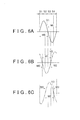
- FIG. 6A to FIG. 6C schematically show the signal waveforms of the output signals V1, V2 and V3 of the first, second and third magnetic sensors 21, 22 and 23 at the time when the magnetic pole pair formed of the magnetic pole M0 and the magnetic pole M1 of the rotor 1 passes the first magnetic sensor 21.
- S1 indicates the region in which the first magnetic sensor 21 and the second magnetic sensor 22 both sense the magnetic pole M0.
- S2 indicates the region in which the first magnetic sensor 21 senses the magnetic pole M0 and the second magnetic sensor 22 senses the magnetic pole M1.
- S3 indicates the region in which the first magnetic sensor 21 and the second magnetic sensor 22 both sense the magnetic pole M1.
- S4 indicates the region in which the first magnetic sensor 21 senses the magnetic pole M1 and the second magnetic sensor 22 senses the magnetic pole M2.
- both output signal values V1 and V2 satisfy the first condition that V1 ⁇ 0 and V2 > 0.
- both output signal values V1 and V2 satisfy the second condition that V1 ⁇ 0 and V2 ⁇ 0.
- both output signal values V1 and V2 satisfy the third condition that V1 ⁇ 0 and V2 ⁇ 0.
- both output signal values V1 and V2 satisfy the fourth condition that V1 ⁇ 0 and V2 ⁇ 0.
- the rotation angle computing device 20 determines that the magnetic pole sensed by the first magnetic sensor 21 is different from the magnetic pole sensed by the second magnetic sensor 22 when the second condition (V1 ⁇ 0 and V2 ⁇ 0) or the fourth condition (V1 ⁇ 0 and V2 ⁇ 0) is satisfied, and determines that the magnetic pole sensed by the first magnetic sensor 21 is the same as the magnetic pole sensed by the second magnetic sensor 22 when neither the second condition nor the fourth condition is satisfied.
- step S4 the rotation angle computing device 20 executes the process of detecting a transition in magnetic pole and updating a relative pole number.
- the rotation angle computing device 20 executes the process of detecting a transition in magnetic pole sensed by the first magnetic sensor 21 and a transition in magnetic pole sensed by the second magnetic sensor 22. Then, when the rotation angle computing device 20 has detected a transition in magnetic pole sensed by the first magnetic sensor 21, the rotation angle computing device 20 updates the first relative pole number p1. In addition, when the rotation angle computing device 20 has detected a transition in magnetic pole sensed by the second magnetic sensor 22, the rotation angle computing device 20 updates the second relative pole number p2.
- a transition in magnetic pole sensed by the first magnetic sensor 21 is classified into the following four cases.
- the rotation angle computing device 20 determines whether a transition in magnetic pole of any one of the above descriptions a) to d) has occurred. When the rotation angle computing device 20 determines that a transition in magnetic pole has occurred, the rotation angle computing device 20 updates the first relative pole number p1. The rotation angle computing device 20 determines whether the following first determination condition is satisfied in order to determine whether there is a transition in magnetic pole in the above description a) (see Qa in FIG. 3 ).
- ⁇ V2 denotes the absolute value of the difference between the immediately preceding value and current value of the second output signal V2
- ⁇ V3 denotes the absolute value of the difference between the immediately preceding value and current value of the third output signal V3.
- Second Determination Condition "V2 > 0 in the case where ⁇ V2 ⁇ ⁇ V3, and V3 ⁇ 0 in the case where ⁇ V2 ⁇ ⁇ V3" and "the immediately preceding value of V1 ⁇ 0" and "the current value of V1 ⁇ 0".
- the rotation angle computing device 20 determines that the second determination condition is satisfied, the rotation angle computing device 20 updates the first relative pole number p1 to a value larger by 1. Note that, when the first relative pole number p1 is "9", a value larger by 1 than "9” is "0".
- the rotation angle computing device 20 determines whether the following third determination condition is satisfied in order to determine whether there is a transition in magnetic pole in the above description c) (see Qc of FIG. 3 ).
- Third Determination Condition "V2 > 0 in the case where ⁇ V2 ⁇ ⁇ V3, and V3 ⁇ 0 in the case where ⁇ V2 ⁇ ⁇ V3" and "the immediately preceding value of V1 ⁇ 0" and "the current value of V1 ⁇ 0".
- the rotation angle computing device 20 updates the first relative pole number p1 to a value smaller by 1. Note that, when the first relative pole number p1 is "0", a value smaller by 1 than "0" is "9".
- the rotation angle computing device 20 determines whether the following fourth determination condition is satisfied in order to determine whether there is a transition in magnetic pole in the above description d) (see Qd of FIG. 3 ).
- Fourth Determination Condition "V2 ⁇ 0 in the case where ⁇ V2 ⁇ ⁇ V3, and V3 > 0 in the case where ⁇ V2 ⁇ ⁇ V3" and "the immediately preceding value of V1 ⁇ 0" and "the current value of V1 > 0".
- the rotation angle computing device 20 updates the first relative pole number p1 to a value smaller by 1.
- the rotation angle computing device 20 determines whether the following four determination conditions (fifth determination condition to eighth determination condition) are satisfied in order to determine whether a transition in magnetic pole sensed by the second magnetic sensor 22 has occurred.
- ⁇ V1 denotes the absolute value of the difference between the immediately preceding value and current value of the first output signal V1.
- Fifth Determination Condition transition from a north pole to a south pole in the case of the normal rotation direction: "V1 > 0 in the case where ⁇ V1 ⁇ ⁇ V3, and V3 ⁇ 0 in the case where ⁇ V1 ⁇ ⁇ V3" and "the immediately preceding value of V2 > 0" and "the current value of V2 ⁇ 0".
- the rotation angle computing device 20 updates the second relative pole number p2 to a value smaller by 1. Note that, when the second relative pole number p2 is "0", a value smaller by 1 than "0" is "9".
- Tenth Determination Condition transition from a south pole to a north pole in the case of the normal rotation direction: "V1> 0 in the case where ⁇ V1 ⁇ ⁇ V2, and V2 ⁇ 0 in the case where ⁇ V1 ⁇ ⁇ V2" and "the immediately preceding value of V3 ⁇ 0" and "the current value of V3 ⁇ 0".
- Twelfth Determination Condition transition from a south pole to a north pole in the case of the reverse rotation direction: "V1 ⁇ 0 in the case where ⁇ V1 ⁇ ⁇ V2, and V2 > 0 in the case where ⁇ V1 ⁇ ⁇ V2" and "the immediately preceding value of V3 ⁇ 0" and "the current value of V3 > 0".
- a transition in magnetic pole sensed by the selected magnetic sensor is detected using the above described determination conditions, even if a stuck abnormality occurs in one of the output signals of the two magnetic sensors other than the selected magnetic sensor, a transition in magnetic pole sensed by the selected magnetic sensor may be accurately detected. This will be examined by way of an example in which a transition in magnetic pole sensed by the first magnetic sensor 21 is detected.
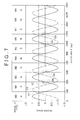
- FIG. 7 shows the output signals in the case where the value of the second output signal V2 is fixed at 0.5 due to a stuck abnormality.
- the first determination condition is that "V2 ⁇ 0 in the case where ⁇ V2 ⁇ ⁇ V3, and V3 > 0 in the case where ⁇ V2 ⁇ ⁇ V3" and "the immediately preceding value of V1 > 0" and "the current value of V1 ⁇ 0".
- the value of the second output signal V2 in which a stuck abnormality has occurred hardly changes, so ⁇ V2 is a small value. Therefore, at the time point of a transition in magnetic pole indicated by the arrow in the ellipse Qa of FIG. 7 , ⁇ V2 ⁇ ⁇ V3.
- the second determination condition is that "V2 > 0 in the case where ⁇ V2 ⁇ ⁇ V3, and V3 ⁇ 0 in the case where ⁇ V2 ⁇ ⁇ V3" and "the immediately preceding value of V1 ⁇ 0" and "the current value of V1 ⁇ 0". Because ⁇ V2 is a small value, at the time point of a transition in magnetic pole indicated by the arrow in the ellipse Qb of FIG. 7 , ⁇ V2 ⁇ ⁇ V3.
- the third determination condition is that "V2 > 0 in the case where ⁇ V2 ⁇ ⁇ V3, and V3 ⁇ 0 in the case where ⁇ V2 ⁇ ⁇ V3" and "the immediately preceding value of V1 ⁇ 0" and "the current value of V1 ⁇ 0". Because ⁇ V2 is a small value, at the time point of a transition in magnetic pole indicated by the arrow in the ellipse Qc of FIG. 7 , ⁇ V2 ⁇ ⁇ V3.
- the fourth determination condition is that "V2 ⁇ 0 in the case where ⁇ V2 ⁇ ⁇ V3, and V3 > 0 in the case where ⁇ V2 ⁇ ⁇ V3 and "the immediately preceding value of V1 ⁇ 0" and "the current value of V1 > 0". Because ⁇ V2 is a small value, at the time point of a transition in magnetic pole indicated by the arrow in the ellipse Qd of FIG. 7 , ⁇ V2 ⁇ ⁇ V3.
- step S5 the rotation angle computing device 20 computes the electric angle ⁇ e on the basis of the output signal values V1, V2 and V3 read in step S1. Note that, at this time, the rotation angle computing device 20 determines whether a stuck abnormality has occurred in one of the output signals V1, V2 and V3. Determination as to whether a stuck abnormality has occurred in any one of the output signals V1, V2 and V3 is, for example, made by checking whether the output signal value hardly changes over a predetermined number of times for each of the output signals V1, V2 and V3. That is, when the output signal value hardly changes over a predetermined number of times, the rotation angle computing device 20 determines that a stuck abnormality has occurred in the output signal corresponding to that output signal value.
- the rotation angle computing device 20 computes the first electric angle ⁇ e1 corresponding to the rotation angle of the rotor 1 on the basis of the first output signal V1 and the second output signal V2. In addition, the rotation angle computing device 20 computes the second electric angle ⁇ e2 corresponding to the rotation angle of the rotor 1 on the basis of the first output signal V1 and the third output signal V3. In addition, the rotation angle computing device 20 computes the third electric angle ⁇ e3 corresponding to the rotation angle of the rotor 1 on the basis of the second output signal V2 and the third output signal V3. A method of computing the first, second and third electric angles ⁇ e1, ⁇ e2 and ⁇ e3 will be described later.
- the final electric angle ⁇ e is, for example, computed according to Expression 2. That is, the rotation angle computing device 20 computes the mean value of the first, second and third electric angles ⁇ e1, ⁇ e2 and ⁇ e3 as the final electric angle ⁇ e.
- ⁇ e ⁇ e ⁇ 1 + ⁇ e ⁇ 2 + ⁇ e ⁇ 3 / 3 Note that, when it is determined that all the output signals V1, V2 and V3 are normal, the rotation angle computing device 20 is able to compute the median value of the first, second and third electric angles ⁇ e1, ⁇ e2 and ⁇ e3 as the final electric angle ⁇ e.
- the rotation angle computing device 20 may determine, as the final rotation angle ⁇ , the average of the median of the first rotation angle ⁇ 1 , the second rotation angle ⁇ 2 , and the third rotation angle ⁇ 3 , and another one of the rotation angles ⁇ 1 , ⁇ 2 , and ⁇ 3 which is closer to the median. Furthermore, in this case, the rotation angle computing device 20 may determine one of the first, second and third electric angles ⁇ e1, ⁇ e2 and ⁇ e3 as the final electric angle ⁇ e.
- the rotation angle computing device 20 determines that the first output signal V1 is abnormal and the second and third output signals V2 and V3 are normal, the rotation angle computing device 20 determines the third electric angle ⁇ e3 computed on the basis of the second and third output signals V2 and V3 as the final electric angle ⁇ e. In addition, when the rotation angle computing device 20 determines that the second output signal V2 is abnormal and the first and third output signals V1 and V3 are normal, the rotation angle computing device 20 determines the second electric angle ⁇ e2 computed on the basis of the first and third output signals V1 and V3 as the final electric angle ⁇ e.
- the rotation angle computing device 20 determines the first electric angle ⁇ e1 computed on the basis of the first and second output signals V1 and V2 as the final electric angle ⁇ e. Note that, when the rotation angle computing device 20 determines that two or more of the three output signals V1, V2 and V3 are abnormal, the rotation angle computing device 20 is not able to compute the electric angle ⁇ e. Therefore, the rotation angle computing device 20 outputs a motor stop command to the motor controller 30, and stops the rotation angle computing process.
- the rotation angle computing device 20 generates the signal V 23 according to Expression 7.
- V 23 cos ⁇ e'
- the rotation angle computing device 20 computes the third electric angle ⁇ e3 according to Expression 9.
- ⁇ e3 ⁇ e3' - 120° Expression 9
- the rotation angle computing device 20 determines whether the first output signal V1 is determined to be abnormal (stuck abnormality) (step S6).
- the rotation angle computing device 20 sets the value of the first relative pole number p1 as the mechanical angle computing pole number p used to compute the relative mechanical angle ⁇ m (step S7).
- the mechanical angle computing pole number p indicates the relative pole number of the magnetic pole sensed by the first magnetic sensor 21.
- the first relative pole number p1 properly indicates the relative pole number of the magnetic pole sensed by the first magnetic sensor 1. Therefore, the value of the first relative pole number p is set as the mechanical angle computing pole number p. Then, the process proceeds to step S11.
- the rotation angle computing device 20 computes the mechanical angle computing pole number p on the basis of the second relative pole number p2. Specifically, the rotation angle computing device 20 determines whether the magnetic pole sensed by the first magnetic sensor 21 is the same as or different from the magnetic pole sensed by the second magnetic sensor 22 (step S8). More specifically, it is determined whether the electric angle ⁇ e computed in step S5 falls within the range of 60° ⁇ ⁇ e ⁇ 180° or 240° ⁇ ⁇ e ⁇ 360°. In FIG. 6A and FIG.
- the magnetic pole sensed by the first magnetic sensor 21 is the same as the magnetic pole sensed by the second magnetic sensor 22.
- the magnetic pole sensed by the first magnetic sensor 21 is different from the magnetic pole sensed by the second magnetic sensor 22.
- the electric angle ⁇ e falls within the range of 60° ⁇ ⁇ e ⁇ 180°.
- the electric angle ⁇ e falls within the range of 240° ⁇ ⁇ e ⁇ 360°.
- the rotation angle computing device 20 determines that the magnetic pole sensed by the first magnetic sensor 21 is different from the magnetic pole sensed by the second magnetic sensor 22. Then, in this case, the rotation angle computing device 20 sets a value smaller by 1 than the second relative pole number p2 as the mechanical angle computing pole number p (step S9). Then, the process proceeds to step S11.
- step S8 when it is determined in step S8 that the electric angle ⁇ e falls outside both the range of 60° ⁇ ⁇ e ⁇ 180° and the range of 240° ⁇ ⁇ e ⁇ 360° (NO in step S8), the rotation angle computing device 20 determines that the magnetic pole sensed by the first magnetic sensor 21 is the same as the magnetic pole sensed by the second magnetic sensor 22. Thus, in this case, the rotation angle computing device 20 sets the value of the second relative pole number p2 as the mechanical angle computing pole number p (step S10). Then, the process proceeds to step S11.
- step S11 the rotation angle computing device 20 uses the electric angle ⁇ e computed in step S5 and the mechanical angle computing pole number p to compute the relative mechanical angle ⁇ m according to Expression 10. Then, the electric angle ⁇ e computed in step S5 and the relative mechanical angle ⁇ m computed in step S11 are given to the motor controller 30.
- the rotation angle computing device 20 is able to compute the electric angle ⁇ e and the relative mechanical angle ⁇ m in each predetermined computation cycle and to give the computed electric angle ⁇ e and relative mechanical angle ⁇ m to the motor controller 30. Even when a stuck abnormality has occurred in one of the output signals V1, V2 and V3 of the three magnetic sensors 21, 22 and 23, the rotation angle computing device 20 is able to accurately compute the electric angle ⁇ e.
- the rotation angle computing device 20 is able to accurately detect a transition in magnetic pole sensed by at least one of the three magnetic sensors 21, 22 and 23.
- the phase difference among the output signals V1, V2 and V3 of the magnetic sensors 21, 22 and 23 is 120° in electric angle.
- the phase difference may be an angle other than 120°.
- the phase difference among the output signals V1, V2 and V3 may be an angle that falls within the range of 20° to 35° in electric angle, the range of 55° to 70° in electric angle, the range of 110° to 125° in electric angle or the range of 145° to 160° in electric angle.
- the rotor 1 has five magnetic pole pair.
- the number of magnetic pole pairs may be smaller than five or larger than five.
- the relative pole number p1 of the magnetic pole sensed by the first magnetic sensor 21 and the relative pole number p2 of the magnetic pole sensed by the second magnetic sensor 22 are set and updated.
- the relative pole number p1 of the magnetic pole sensed by the first magnetic sensor 21 and the relative pole number p3 of the magnetic pole sensed by the third magnetic sensor 23 may be set and updated.
- the relative pole number p1 of the magnetic pole sensed by the first magnetic sensor 21, the relative pole number p2 of the magnetic pole sensed by the second magnetic sensor 22 and the relative pole number p3 of the magnetic pole sensed by the third magnetic sensor 23 may be set and updated.
- the absolute value of the difference between the immediately preceding value and current value of that sensor signal is extremely large.
- determination regarding a transition in magnetic pole is made using the immediately preceding value and the current value the difference between which is extremely large in absolute value are used without considering the above abnormal condition, erroneous determination may possibly be made.
- the absolute value of the difference between an immediately preceding value and current value of a sensor signal, which is subjected to determination regarding a transition in magnetic pole is compared with a predetermined threshold. When the absolute value of the difference is larger than the predetermined threshold, it is determined that an abnormality has occurred in that signal and then the signal is not used in determination regarding a transition in magnetic pole.
- the invention may be applied to a case where the rotation angle of a rotor, other than the rotor of the brushless motor, is detected.
- various design changes may be applied within the range of the matter recited in the appended claims.
Landscapes
- Physics & Mathematics (AREA)
- General Physics & Mathematics (AREA)
- Transmission And Conversion Of Sensor Element Output (AREA)
- Control Of Motors That Do Not Use Commutators (AREA)
Abstract
Description
- The invention relates to a rotation angle detecting device that detects the rotation angle of a rotor, for example, a rotor of a brushless motor.
- In order to control a brushless motor used in an electric power steering system, or the like, currents need to be passed through stator coils in accordance with the rotation angle of a rotor. Therefore, there is known a rotation angle detecting device that detects the rotation angle of the rotor of the brushless motor using a detection rotor that rotates in accordance with rotation of the brushless motor. Specifically, as shown in
FIG. 8 , a detection rotor 101 (hereinafter, referred to as "rotor 101") has acylindrical magnet 102 with a plurality of magnetic pole pairs. The number of magnetic pole pairs of thecylindrical magnet 102 corresponds to the number of magnetic pole pairs of the rotor of the brushless motor. Twomagnetic sensors rotor 101 at a predetermined angular interval about the rotation axis of therotor 101. Themagnetic sensors 2003-241411 JP-A-2003-241411 2002-213944 JP-A-2002-213944 - In this example, the
magnet 102 has the five magnetic pole pairs (M0, M1), (M2, M3), (M4, M5), (M6, M7) and (M8, M9). That is, themagnet 102 has ten magnetic poles M0 to M9 that are arranged at equiangular intervals. The magnetic poles M0 to M9 are arranged at angular intervals of 36° (180° in electric angle) about the rotation axis of therotor 101. In addition, the twomagnetic sensors rotor 101. - The direction indicated by the arrow in
FIG. 8 is defined as the normal rotation direction of thedetection rotor 101. Then, as therotor 101 is rotated in the normal direction, the rotation angle of therotor 101 increases, while, as therotor 101 is rotated in the reverse direction, the rotation angle of therotor 101 decreases. As shown inFIG. 9 , themagnetic sensors rotor 101 rotates by an angle (72° (360° in electric angle)) corresponding to a single magnetic pole pair, as one cycle. - The angular range of one rotation of the
rotor 101 is divided into five sections that correspond to the five magnetic pole pairs, and then the angle of therotor 101, which is expressed on the condition that the start position of each section is 0° and the end position of each section is 360°, is termed the electric angle θe of therotor 101. In this case, the angular widths of the ten magnetic poles are equal to one another, so the electric angle θe of therotor 101 coincides with the electric angle of the rotor of the brushless motor. In this example, the firstmagnetic sensor 121 outputs an output signal V1 (= A1●sinθe), and the secondmagnetic sensor 122 outputs an output signal V2 (= A2●cosθe). A1 and A2 are amplitudes. If the amplitude A1 of the output signal V1 and the amplitude A2 of the output signal V2 are equal to each other, the electric angle θe of therotor 101 may be obtained using both output signals V1 and V2 according toExpression 1 shown below. -

- When a brushless motor used in an electric power steering system, or the like, is controlled, a steering angle or the angular velocity of a steering angle may be used to control the brushless motor. The steering angle and the angular velocity of the steering angle may be computed on the basis of the mechanical angle of the rotor of the brushless motor. In addition, the angular velocity of the steering angle may be computed on the basis of the mechanical angle (hereinafter, referred to as "relative mechanical angle") of the rotor with respect to the initial position of the rotor at the time of the start of rotation angle computing process.
- When the mechanical angle or relative mechanical angle of the rotor is detected, it is necessary to detect a magnetic pole transition in the output signal of a magnetic sensor. Here, detecting a magnetic pole transition in the output signal of the magnetic sensor is detecting a transition in magnetic pole sensed by the magnetic sensor and the direction of the transition in magnetic pole. A magnetic pole transition in the output signal of the magnetic sensor may be detected, for example, on the basis of the output signals V1 and V2 of the two respective
magnetic sensors FIG. 8 . - If the amplitudes A1 and A2 of the output signals V1 and V2 of the two respective
magnetic sensors magnetic sensors -
FIG. 9 shows the output signals V1 and V2 of themagnetic sensors rotor 101 is set at 0° when the boundary between the magnetic pole M9 and magnetic pole M0 of therotor 101 faces the firstmagnetic sensor 121. However, the rotor angle is expressed by an angle that is obtained by multiplying an actual mechanical angle by the number of magnetic pole pairs ("5" in this example) of therotor 101. In addition, inFIG. 9 , the magnetic poles M0 to M9 each indicate the magnetic pole that is sensed by the firstmagnetic sensor 121. - A transition in magnetic pole sensed by the first
magnetic sensor 121 is classified into the following four cases. - a) The magnetic pole sensed by the first
magnetic sensor 121 changes from the north pole to the south pole when therotor 101 is rotating in the normal direction. For example, as indicated by the arrow in the ellipse indicated by the reference sign Qa inFIG. 9 , the magnetic pole sensed by the firstmagnetic sensor 121 changes from M2 to M3. - b) The magnetic pole sensed by the first
magnetic sensor 121 changes from the south pole to the north pole when therotor 101 is rotating in the normal direction. For example, as indicated by the arrow in the ellipse indicated by the reference sign Qb inFIG. 9 , the magnetic pole sensed by the firstmagnetic sensor 121 changes from M1 to M2. - c) The magnetic pole sensed by the first
magnetic sensor 121 changes from the north pole to the south pole when therotor 101 is rotating in the reverse direction. For example, as indicated by the arrow in the ellipse indicated by the reference sign Qc inFIG. 9 , the magnetic pole sensed by the firstmagnetic sensor 121 changes from M6 to M5. - d) The magnetic pole sensed by the first
magnetic sensor 121 changes from the south pole to the north pole when therotor 101 is rotating in the reverse direction. For example, as indicated by the arrow in the ellipse indicated by the reference sign Qd inFIG. 9 , the magnetic pole sensed by the firstmagnetic sensor 121 changes from M7 to M6. - The transition in magnetic pole in the above description a) (see Qa in
FIG. 9 ) may be detected by determining whether the following first determination condition is satisfied.
First Determination Condition: "V2 < 0" and "immediately preceding value of V1 > 0" and "current value of V1 ≤ 0"
The transition in magnetic pole in the above description b) (see Qb inFIG. 9 ) may be detected by determining whether the following second determination condition is satisfied. - Second Determination Condition: "V2 > 0" and "immediately preceding value of V1 < 0" and "current value of V1 ≥ 0"
The transition in magnetic pole in the above description c) (see Qc inFIG. 9 ) may be detected by determining whether the following third determination condition is satisfied.
Third Determination Condition: "V2 > 0" and "immediately preceding value of V1 ≥ 0" and "current value of V1 < 0"
The transition in magnetic pole in the above description d) (see Qd inFIG. 9 ) may be detected by determining whether the following fourth determination condition is satisfied. - Fourth Determination Condition: "V2 < 0" and "immediately preceding value of V1 ≤ 0" and "current value of V1 > 0"
That is, when it is determined that the first determination condition is satisfied, it is determined that the transition in magnetic pole in the above description a) has occurred. When it is determined that the second determination condition is satisfied, it is determined that the transition in magnetic pole in the above description b) has occurred. When it is determined that the third determination condition is satisfied, it is determined that the transition in magnetic pole in the above description c) has occurred. When it is determined that the fourth determination condition is satisfied, it is determined that the transition in magnetic pole in the above description d) has occurred. - If the magnetic sensor malfunctions, the value of the output signal may be fixed at a certain value. Such an abnormality in output signal is termed stuck abnormality. If a stuck abnormality occurs in the first output signal V1 or the second output signal V2, a transition in magnetic pole cannot be accurately detected. For example, if the value of the second output signal V2 is fixed at "0", none of the first to fourth determination conditions is satisfied. Therefore, a transition in magnetic pole in the above descriptions a) to d) cannot be detected.
- In addition, also when the value of the second output signal V2 is fixed at a value other than "0", such as "0.5", a transition in magnetic pole is erroneously detected.
FIG. 10 shows the output signals V1 and V2 of themagnetic sensors FIG. 10 , in a transition in magnetic pole indicated by the arrow within the ellipse Qa, V2 should be smaller than 0 but V2 is actually larger than 0, so the first determination condition is not satisfied, and the third determination condition is satisfied. Therefore, the transition in magnetic pole in the above description a) is erroneously detected as the transition in magnetic pole in the above description c). Similarly, inFIG. 10 , in a transition in magnetic pole indicated by the arrow in the ellipse Qd, V2 should be smaller than 0 but V2 is actually larger than 0, so the fourth determination condition is not satisfied, and the second determination condition is satisfied. Therefore, the transition in magnetic pole in the above description d) is erroneously detected as the transition in magnetic pole in the above description b). - It is an object of the invention to provide a rotation angle detecting device that is able to accurately detect a transition in magnetic pole even when a stuck abnormality occurs in one of a plurality of sinusoidal signals.
- An aspect of the invention relates to a rotation angle detecting device that includes a detection rotor that rotates in accordance with rotation of a rotor and that has a plurality of magnetic poles, and a sensor that outputs three sinusoidal signals which have a phase difference of a predetermined degree in accordance with rotation of the detection rotor, the rotation angle detecting device detecting a rotation angle of the rotor based on the sinusoidal signals. The rotation angle detecting device includes: a signal reading unit that reads the sinusoidal signals in each predetermined computation cycle; and a detecting unit that detects a magnetic pole transition in at least one of the sinusoidal signals on the basis of the sinusoidal signals read by the signal reading unit. When the sinusoidal signal in which a magnetic pole transition is detected is a first sinusoidal signal, one of the other two sinusoidal signals is a second sinusoidal signal and the other one of the other two sinusoidal signals is a third sinusoidal signal, the detecting unit detects a magnetic pole transition in the first sinusoidal signal based on a current value of one of the second sinusoidal signal and the third sinusoidal signal, an absolute value of a difference between an immediately preceding value and the current value of the one of the second and third sinusoidal signals being larger than an absolute value of a difference between an immediately preceding value and the current value of the other of the second and third sinusoidal signals, an immediately preceding value of the first sinusoidal signal and a current value of the first sinusoidal signal.
- Features, advantages, and technical and industrial significance of exemplary embodiments of the invention will be described below with reference to the accompanying drawings, in which like numerals denote like elements, and wherein:
-
FIG. 1 is a schematic view that shows the configuration in the case where a rotation angle detecting device according to an embodiment of the invention is applied to a rotation angle detecting device that is used to detect the rotation angle of a rotor of a brushless motor; -
FIG. 2 is a schematic view that shows the configuration of a detection rotor; -
FIG. 3 is a schematic view that shows the output signal waveforms of first, second and third magnetic sensors and the magnetic pole sensed by the first magnetic sensor; -
FIG. 4 is a flowchart that shows the procedure of rotation angle computing process executed by a rotation angle computing device; -
FIG. 5 is a flowchart that shows the procedure of the process of setting a relative pole number in step S3 ofFIG. 4 ; -
FIG. 6A to FIG. 6C are schematic views for illustrating the process of setting a relative pole number; -
FIG. 7 is a schematic view that shows the output signal waveforms in the case where the value of the second output signal is fixed at 0.5, and a magnetic pole sensed by the first magnetic sensor; -
FIG. 8 is a schematic view for illustrating a rotation angle detecting method executed by an existing rotation angle detecting device; -
FIG. 9 is a schematic view that shows the output signal waveform of a first magnetic sensor and the output signal waveform of a second magnetic sensor; and -
FIG. 10 is a schematic view for illustrating the fact that a transition in magnetic pole is erroneously detected in the case where a stuck abnormality has occurred in one of the output signals of the two magnetic sensors. - Hereinafter, an embodiment in which the invention is applied to a rotation angle detecting device used to detect the rotation angle of a rotor of a brushless motor will be described in detail with reference to the accompanying drawings.
FIG. 1 is a schematic view that shows the configuration in the case where a rotation angle detecting device according to the embodiment of the invention is applied to the rotation angle detecting device that is used to detect the rotation angle of the rotor of the brushless motor. The rotation angle detecting device includes a detection rotor (hereinafter, simply referred to as "rotor 1") that rotates with rotation of thebrushless motor 10. As shown inFIG. 2 , therotor 1 includes acylindrical magnet 2 with a plurality of magnetic pole pairs that correspond to magnetic pole pairs of the rotor of thebrushless motor 10. - The
magnet 2 has five magnetic pole pairs (M0, M1), (M2, M3), (M4, M5), (M6, M7) and (M8, M9). That is, themagnet 2 has ten magnetic poles M0 to M9 that are arranged at equiangular intervals. The magnetic poles M0 to M9 are arranged at angular intervals of 36° (180° in electric angle) about the rotation axis of therotor 1. Threemagnetic sensors rotor 1 at angular intervals of a predetermined angle (24° (120° in electric angle)) about the rotation axis of therotor 1. These threemagnetic sensors magnetic sensor 21, the secondmagnetic sensor 22 and the thirdmagnetic sensor 23, respectively. Each magnetic sensor may include, for example, an element of which the electrical characteristic change under the influence of the magnetic field, such as a Hall element and a magnetoresistance element (MR element). - The direction indicated by the arrow in
FIG. 2 is defined as the normal rotation direction of therotor 1. As therotor 1 is rotated in the normal direction, the rotation angle of therotor 1 increases; whereas, as therotor 1 rotates in the reverse direction, the rotation angle of therotor 1 decreases. As shown inFIG. 3 , themagnetic sensors rotor 1 rotates by an angle (72° (360° in electric angle)) corresponding to a single magnetic pole pair, as one cycle. -
FIG. 3 shows the output signals V1, V2 and V3 of the respectivemagnetic sensors rotor 1 is set at 0° when the boundary between the magnetic pole M9 and magnetic pole M0 of therotor 1 faces the firstmagnetic sensor 21. The rotor angle (degrees) of the abscissa axis inFIG. 3 indicates an angle obtained by multiplying a mechanical angle by the number of magnetic pole pairs ("5" in this embodiment). In addition,FIG. 3 shows the magnetic poles M0 to M9 sensed by the firstmagnetic sensor 21 in accordance with a rotor angle. - The mechanical angle of the
rotor 1 with respect to the initial position of therotor 1 at the time of the start of rotation angle computing process is defined as a relative mechanical angle θm. Note that, in this embodiment, the relative mechanical angle θm is expressed by a value obtained by multiplying the mechanical angle of therotor 1 with respect to the initial position of therotor 1 at the time of the start of rotation angle computing process, by the number of magnetic pole pairs of the rotor 1 ("5" in this example). The angular range of one rotation of therotor 1 is divided into five sections that correspond to the five magnetic pole pairs, and then the angle of therotor 1, which is expressed on the condition that the start position of each section is 0° and the end position of each section is 360°, is termed the electric angle θe of therotor 1. In this case, the angular widths of the ten magnetic poles are equal to one another, so the electric angle θe of therotor 1 coincides with the electric angle of the rotor of the brushless motor. - Here, the first
magnetic sensor 21 outputs the output signal V1 (= A1●sinθe) for each of the sections that correspond to the five magnetic pole pairs. In this case, the secondmagnetic sensor 22 outputs the output signal V2 (= A2●sin(θe+120°)) for each of the sections that correspond to the five magnetic pole pairs. In addition, the thirdmagnetic sensor 23 outputs the output signal V3 (= A3●sin(θe+240°) = A3●cosθ)) for each of the sections that correspond to the five magnetic pole pairs. A1, A2 and A3 respectively indicate amplitudes. That is, themagnetic sensors magnetic sensors - If the amplitudes A1, A2 and A3 of the output signals V1, V2 and V3 of the three
magnetic sensors magnetic sensors V 1 = sinθe, V2 = sin(θe+120°) and V3 = sin(θe+240°) = cosθe, respectively. - Referring back to
FIG. 1 , the output signals V1, V2 and V3 of themagnetic sensors angle computing device 20. The rotationangle computing device 20 computes the electric angle θe of therotor 1 on the basis of the output signals V1, V2 and V3 of themagnetic sensors angle computing device 20 computes the relative mechanical angle θm of therotor 1 on the basis of the obtained electric angle θe, and the like. The rotationangle computing device 20 is formed of, for example, a microcomputer, and includes a central processing unit (CPU) and memories (a ROM, a RAM, a rewritable nonvolatile memory, and the like). - The electric angle θe and relative mechanical angle θm computed by the rotation
angle computing device 20 are given to amotor controller 30. Themotor controller 30 uses the electric angle θe and relative mechanical angle θm received from the rotationangle computing device 20 to control thebrushless motor 10. In order to compute the relative mechanical angle θm, it is necessary to detect a magnetic pole transition in at least one of the output signals V1, V2 and V3 (a transition in magnetic pole sensed by at least one of themagnetic sensors angle computing device 20 has the following function. That is, when a magnetic pole transition in the output signal of a selected magnetic sensor is detected, even if a stuck abnormality occurs in one of the output signals of the two magnetic sensors other than the selected magnetic sensor, the rotationangle computing device 20 is able to accurately detect a transition in magnetic pole sensed by the selected magnetic sensor. In addition, the rotationangle computing device 20 has the function of being able to accurately compute the relative mechanical angle θm even if a stuck abnormality occurs in one of the output signals of themagnetic sensors -
FIG. 4 is a flowchart that shows the procedure of rotation angle computing process executed by the rotationangle computing device 20. The rotation angle computing process shown inFIG. 4 is repeatedly executed at predetermined computation intervals. A relative number, allocated to each magnetic pole using the magnetic pole sensed by the firstmagnetic sensor 21 at the time of the start of rotation angle computing process as a reference magnetic pole, is defined as a relative pole number. The relative pole number sensed by the first magnetic sensor 21 (hereinafter, referred to as "first relative pole number") is denoted by a variable p1, and the relative pole number sensed by the second magnetic sensor 22 (hereinafter, referred to as "second relative pole number") is denoted by a variable p2. In this embodiment, when the magnetic pole sensed by the firstmagnetic sensor 21 at the time of the start of rotation angle computing process (reference magnetic pole) is a north pole, the relative pole number "0" is allocated to that magnetic pole. On the other hand, when the magnetic pole sensed by the firstmagnetic sensor 21 at the time of the start of rotation angle computing process (reference magnetic pole) is a south pole, the relative pole number "1" is allocated to that magnetic pole. - When the rotation angle computing process is started, the rotation
angle computing device 20 reads the values of the output signals V1, V2 and V3 of the respectivemagnetic sensors angle computing device 20 stores the output signal values that have been read so far since the computation cycle that is multiple cycles before the present computation cycle. - When the output signal values V1, V2 and V3 are read in step S1, the rotation
angle computing device 20 determines whether the current process is the first process after the start of rotation angle computing process (step S2). When the current process is the first process after the start of rotation angle computing process (YES in step S2), the rotationangle computing device 20 executes the process of setting a relative pole number (step S3). -
FIG. 5 shows the detailed procedure of the process of setting a relative pole number.
The rotationangle computing device 20 initially determines whether the value of the first output signal V1 is larger than 0 (step S21). When the value of the first output signal V1 is larger than 0 (YES in step S21), the rotationangle computing device 20 determines that the magnetic pole sensed by the first magnetic sensor 21 (reference magnetic pole) is a north pole, and then sets the first relative pole number p1 at 0 (step S24). Then, the process proceeds to step S26. - On the other hand, when value of the first output signal V1 is smaller than or equal to 0 (NO in step S21), the rotation
angle computing device 20 determines whether the value of the first output signal V1 is smaller than 0 (step S22). When the value of the first output signal V1 is smaller than 0 (YES in step S22), the rotationangle computing device 20 determines that the magnetic pole sensed by the first magnetic sensor 21 (reference magnetic pole) is a south pole, and then sets the first relative pole number p1 at 1 (step S25). Then, the process proceeds to step S26. - When it is determined in step S22 that the value of the first output signal V1 is larger than or equal to 0 (NO in step S22), that is, when the value of the first output signal V1 is 0, the rotation
angle computing device 20 determines whether the value of the second output signal V2 is larger than 0 in order to determine whether the rotor rotation angle (electric angle) is 0° or 180° (step S23). When the value of the second output signal V2 is larger than 0 (YES in step S23), the rotationangle computing device 20 determines that the rotor rotation angle (electric angle) is 0°, and then sets the first relative pole number p1 at 0 (step S24). Then, the process proceeds to step S26. - On the other hand, when the value of the second output signal V2 is smaller than or equal to 0 (NO in step S23), the rotation
angle computing device 20 determines that the rotor rotation angle (electric angle) is 180°, and then sets the first relative pole number p1 at 1 (step S25). Then, the process proceeds to step S26.
Note that the rotationangle computing device 20 may determine in step S23 whether the value of the third output signal V3 is smaller than 0. In this case, when the value of the third output signal V3 is smaller than 0, the rotationangle computing device 20 proceeds to step S24 and then sets the first relative pole number p1 at 0. On the other hand, when the value of the third output signal V3 is larger than or equal to 0, the rotationangle computing device 20 proceeds to step S25 and then sets the first relative pole number p1 at 1. - In step S26, the rotation
angle computing device 20 determines whether the condition "V1 ≥ 0 and V2 ≤ 0" or the condition "V1 < 0 and V2 ≥ 0" is satisfied. When the above condition is satisfied (YES in step S26), the rotationangle computing device 20 determines that the magnetic pole sensed by the firstmagnetic sensor 21 is different from the magnetic pole sensed by the secondmagnetic sensor 22, and then sets the second relative pole number p2 at a number that is larger by 1 than the first relative pole number p1 (step S28). Then, the process returns to step S5 inFIG. 4 . - On the other hand, when the condition of step S26 is not satisfied (NO in step S24), the rotation
angle computing device 20 determines that the magnetic pole sensed by the firstmagnetic sensor 21 is the same as the magnetic pole sensed by the secondmagnetic sensor 22, and then sets the second relative pole number p2 at a number equal to the first relative pole number p1 (step S27). Then, the process returns to step S5 inFIG. 4 . - The reason why it is determined that the magnetic pole sensed by the first
magnetic sensor 21 is different from the magnetic pole sensed by the secondmagnetic sensor 22 when the condition of step S26 is satisfied and it is determined that the magnetic pole sensed by the firstmagnetic sensor 21 is the same as the magnetic pole sensed by the secondmagnetic sensor 22 when the condition of step S26 is not satisfied will be described below. - For example,
FIG. 6A to FIG. 6C schematically show the signal waveforms of the output signals V1, V2 and V3 of the first, second and thirdmagnetic sensors rotor 1 passes the firstmagnetic sensor 21. InFIG. 6A and FIG. 6B , S1 indicates the region in which the firstmagnetic sensor 21 and the secondmagnetic sensor 22 both sense the magnetic pole M0. S2 indicates the region in which the firstmagnetic sensor 21 senses the magnetic pole M0 and the secondmagnetic sensor 22 senses the magnetic pole M1. S3 indicates the region in which the firstmagnetic sensor 21 and the secondmagnetic sensor 22 both sense the magnetic pole M1. S4 indicates the region in which the firstmagnetic sensor 21 senses the magnetic pole M1 and the secondmagnetic sensor 22 senses the magnetic pole M2. - That is, in the regions S1 and S3, the pole number of the magnetic pole sensed by the second
magnetic sensor 22 is equal to the pole number of the magnetic pole sensed by the firstmagnetic sensor 21. On the other hand, in the regions S2 and S4, the pole number of the magnetic pole sensed by the secondmagnetic sensor 22 is larger by 1 than the pole number of the magnetic pole sensed by the firstmagnetic sensor 21.
In the region S1, both output signal values V1 and V2 satisfy the first condition that V1 ≥ 0 and V2 > 0. In the region S2, both output signal values V1 and V2 satisfy the second condition that V1 ≥ 0 and V2 ≤ 0. In the region S3, both output signal values V1 and V2 satisfy the third condition that V1 < 0 and V2 < 0. In the region S4, both output signal values V1 and V2 satisfy the fourth condition that V1 < 0 and V2 ≥ 0. - Then, the rotation
angle computing device 20 determines that the magnetic pole sensed by the firstmagnetic sensor 21 is different from the magnetic pole sensed by the secondmagnetic sensor 22 when the second condition (V1 ≥ 0 and V2 ≤ 0) or the fourth condition (V1 < 0 and V2 ≥ 0) is satisfied, and determines that the magnetic pole sensed by the firstmagnetic sensor 21 is the same as the magnetic pole sensed by the secondmagnetic sensor 22 when neither the second condition nor the fourth condition is satisfied. - Referring back to
FIG. 4 , when it is determined in step S2 that the current process is not the first process after the start of rotation angle computing process (NO in step S2), the process proceeds to step S4. In step S4, the rotationangle computing device 20 executes the process of detecting a transition in magnetic pole and updating a relative pole number. In this embodiment, the rotationangle computing device 20 executes the process of detecting a transition in magnetic pole sensed by the firstmagnetic sensor 21 and a transition in magnetic pole sensed by the secondmagnetic sensor 22. Then, when the rotationangle computing device 20 has detected a transition in magnetic pole sensed by the firstmagnetic sensor 21, the rotationangle computing device 20 updates the first relative pole number p1. In addition, when the rotationangle computing device 20 has detected a transition in magnetic pole sensed by the secondmagnetic sensor 22, the rotationangle computing device 20 updates the second relative pole number p2. - The process of detecting a transition in magnetic pole sensed by the first
magnetic sensor 21 and the process of updating the first relative pole number p1 will be described with reference toFIG. 3 . A transition in magnetic pole sensed by the firstmagnetic sensor 21 is classified into the following four cases. - a) The magnetic pole sensed by the first
magnetic sensor 21 changes from the north pole to the south pole when therotor 1 is rotating in the normal direction. For example, as indicated by the arrow in the ellipse indicated by the reference sign Qa inFIG. 3 , the magnetic pole sensed by the firstmagnetic sensor 21 changes from M2 to M3. - b) The magnetic pole sensed by the first
magnetic sensor 21 changes from the south pole to the north pole when therotor 1 is rotating in the normal direction. For example, as indicated by the arrow in the ellipse indicated by the reference sign Qb inFIG. 3 , the magnetic pole sensed by the firstmagnetic sensor 21 changes from M1 to M2. - c) The magnetic pole sensed by the first
magnetic sensor 21 changes from the north pole to the south pole when therotor 1 is rotating in the reverse direction. For example, as indicated by the arrow in the ellipse indicated by the reference sign Qc inFIG. 3 , the magnetic pole sensed by the firstmagnetic sensor 21 changes from M6 to M5. - d) The magnetic pole sensed by the first
magnetic sensor 21 changes from the south pole to the north pole when therotor 1 is rotating in the reverse direction. For example, as indicated by the arrow in the ellipse indicated by the reference sign Qd inFIG. 3 , the magnetic pole sensed by the firstmagnetic sensor 21 changes from M7 to M6. - The rotation
angle computing device 20 determines whether a transition in magnetic pole of any one of the above descriptions a) to d) has occurred. When the rotationangle computing device 20 determines that a transition in magnetic pole has occurred, the rotationangle computing device 20 updates the first relative pole number p1. The rotationangle computing device 20 determines whether the following first determination condition is satisfied in order to determine whether there is a transition in magnetic pole in the above description a) (see Qa inFIG. 3 ). Note that, ΔV2 denotes the absolute value of the difference between the immediately preceding value and current value of the second output signal V2, and ΔV3 denotes the absolute value of the difference between the immediately preceding value and current value of the third output signal V3. - First Determination Condition: "V2 < 0 in the case where ΔV2 ≥ ΔV3, and V3 > 0 in the case where ΔV2 < ΔV3" and "the immediately preceding value of V1 > 0" and "the current value of V1 ≤ 0".
When the rotationangle computing device 20 determines that the first determination condition is satisfied, the rotationangle computing device 20 updates the first relative pole number p1 to a value larger by 1.
In addition, the rotationangle computing device 20 determines whether the following second determination condition is satisfied in order to determine whether there is a transition in magnetic pole in the above description b) (see Qb ofFIG. 3 ). - Second Determination Condition: "V2 > 0 in the case where ΔV2 ≥ ΔV3, and V3 < 0 in the case where ΔV2 < ΔV3" and "the immediately preceding value of V1 < 0" and "the current value of V1 ≥ 0".
When the rotationangle computing device 20 determines that the second determination condition is satisfied, the rotationangle computing device 20 updates the first relative pole number p1 to a value larger by 1. Note that, when the first relative pole number p1 is "9", a value larger by 1 than "9" is "0". - In addition, the rotation
angle computing device 20 determines whether the following third determination condition is satisfied in order to determine whether there is a transition in magnetic pole in the above description c) (see Qc ofFIG. 3 ).
Third Determination Condition: "V2 > 0 in the case where ΔV2 ≥ ΔV3, and V3 < 0 in the case where ΔV2 < ΔV3" and "the immediately preceding value of V1 ≥ 0" and "the current value of V1 < 0".
When the rotationangle computing device 20 determines that the third determination condition is satisfied, the rotationangle computing device 20 updates the first relative pole number p1 to a value smaller by 1. Note that, when the first relative pole number p1 is "0", a value smaller by 1 than "0" is "9". - In addition, the rotation
angle computing device 20 determines whether the following fourth determination condition is satisfied in order to determine whether there is a transition in magnetic pole in the above description d) (see Qd ofFIG. 3 ).
Fourth Determination Condition: "V2 < 0 in the case where ΔV2 ≥ ΔV3, and V3 > 0 in the case where ΔV2 < ΔV3" and "the immediately preceding value of V1 ≤ 0" and "the current value of V1 > 0".
When the rotationangle computing device 20 determines that the fourth determination condition is satisfied, the rotationangle computing device 20 updates the first relative pole number p1 to a value smaller by 1. - In addition, the rotation
angle computing device 20 determines whether the following four determination conditions (fifth determination condition to eighth determination condition) are satisfied in order to determine whether a transition in magnetic pole sensed by the secondmagnetic sensor 22 has occurred. Note that, ΔV1 denotes the absolute value of the difference between the immediately preceding value and current value of the first output signal V1.
Fifth Determination Condition (transition from a north pole to a south pole in the case of the normal rotation direction): "V1 > 0 in the case where ΔV1 ≥ ΔV3, and V3 < 0 in the case where ΔV1 < ΔV3" and "the immediately preceding value of V2 > 0" and "the current value of V2 ≤ 0".
Sixth Determination Condition (transition from a south pole to a north pole in the case of the normal rotation direction): "V1 < 0 in the case where ΔV1 ≥ ΔV3, and V3 > 0 in the case where ΔV1 < ΔV3" and "the immediately preceding value of V2 < 0" and "the current value of V2 ≥ 0".
Seventh Determination Condition (transition from a north pole to a south pole in the case of the reverse rotation direction): "V1 < 0 in the case where ΔV1 ≥ ΔV3, and V3 > 0 in the case where ΔV1 < ΔV3" and "the immediately preceding value of V2 ≥ 0" and "the current value of V2 < 0".
Eighth Determination Condition (transition from a south pole to a north pole in the case of the reverse rotation direction): "V1 > 0 in the case where ΔV1 ≥ ΔV3, and V3 < 0 in the case where ΔV1 < ΔV3" and "the immediately preceding value of V2 ≤ 0" and "the current value of V2 > 0".
When the fifth determination condition or the sixth determination condition is satisfied, the rotationangle computing device 20 updates the second relative pole number p2 to a value larger by 1. Note that, when the second relative pole number p2 is "9", a value larger by 1 than "9" is "0". On the other hand, when the seventh determination condition or the eighth determination condition is satisfied, the rotationangle computing device 20 updates the second relative pole number p2 to a value smaller by 1. Note that, when the second relative pole number p2 is "0", a value smaller by 1 than "0" is "9". - In this embodiment, it is not determined whether a transition in magnetic pole sensed by the third
magnetic sensor 23 has occurred. However, it is possible to determine whether a transition in magnetic pole sensed by the thirdmagnetic sensor 23 has occurred. Specifically, it is determined whether the following four determination conditions (ninth determination condition to twelfth determination condition) are satisfied to thereby make it possible to determine whether a transition in magnetic pole sensed by the thirdmagnetic sensor 23 has occurred. - Ninth Determination Condition (transition from a north pole to a south pole in the case of the normal rotation direction): "V1 < 0 in the case where ΔV1 ≥ ΔV2, and V2 > 0 in the case where ΔV1 < ΔV2" and "the immediately preceding value of V3 > 0" and "the current value of V3 ≤ 0".
Tenth Determination Condition (transition from a south pole to a north pole in the case of the normal rotation direction): "V1> 0 in the case where ΔV1 ≥ ΔV2, and V2 < 0 in the case where ΔV1 < ΔV2" and "the immediately preceding value of V3 < 0" and "the current value of V3 ≥ 0".
Eleventh Determination Condition (transition from a north pole to a south pole in the case of the reverse rotation direction): "V1 > 0 in the case where ΔV1 ≥ ΔV2, and V2 < 0 in the case where ΔV1 < ΔV2" and "the immediately preceding value of V3 ≥ 0" and "the current value of V3 < 0".
Twelfth Determination Condition (transition from a south pole to a north pole in the case of the reverse rotation direction): "V1 < 0 in the case where ΔV1 ≥ ΔV2, and V2 > 0 in the case where ΔV1 < ΔV2" and "the immediately preceding value of V3 ≤ 0" and "the current value of V3 > 0".
Because a transition in magnetic pole sensed by the selected magnetic sensor is detected using the above described determination conditions, even if a stuck abnormality occurs in one of the output signals of the two magnetic sensors other than the selected magnetic sensor, a transition in magnetic pole sensed by the selected magnetic sensor may be accurately detected. This will be examined by way of an example in which a transition in magnetic pole sensed by the firstmagnetic sensor 21 is detected.FIG. 7 shows the output signals in the case where the value of the second output signal V2 is fixed at 0.5 due to a stuck abnormality. - It is examined whether a transition in magnetic pole indicated by the arrow in the ellipse Qa of
FIG. 7 (transition from a north pole to a south pole in the case of the normal rotation direction) is detected based on the first determination condition. The first determination condition is that "V2 < 0 in the case where ΔV2 ≥ ΔV3, and V3 > 0 in the case where ΔV2 < ΔV3" and "the immediately preceding value of V1 > 0" and "the current value of V1 ≤ 0". The value of the second output signal V2 in which a stuck abnormality has occurred hardly changes, so ΔV2 is a small value. Therefore, at the time point of a transition in magnetic pole indicated by the arrow in the ellipse Qa ofFIG. 7 , ΔV2 < ΔV3. - As a result, whether the requirement "V2 < 0 in the case where ΔV2 ≥ ΔV3, and V3 > 0 in the case where ΔV2 < ΔV3" in the first determination condition is satisfied is determined using not the second output signal V2 in which a stuck abnormality has occurred but the third output signal V3. At the time point of a transition in magnetic pole indicated by the arrow in the ellipse Qa of
FIG. 7 , V3 > 0. Therefore, the first determination condition is satisfied. That is, even when a stuck abnormality has occurred in the second output signal V2, it is possible to accurately detect a transition from a north pole to a south pole in the case of the normal rotation direction on the basis of the first determination condition. - It is examined whether a transition in magnetic pole indicated by the arrow in the ellipse Qb of
FIG. 7 (transition from a south pole to a north pole in the case of the normal rotation direction) is detected based on the second determination condition. The second determination condition is that "V2 > 0 in the case where ΔV2 ≥ ΔV3, and V3 < 0 in the case where ΔV2 < ΔV3" and "the immediately preceding value of V1 < 0" and "the current value of V1 ≥ 0". Because ΔV2 is a small value, at the time point of a transition in magnetic pole indicated by the arrow in the ellipse Qb ofFIG. 7 , ΔV2 < ΔV3. - As a result, whether the requirement "V2 > 0 in the case where ΔV2 ≥ ΔV3, and V3 < 0 in the case where ΔV2 < ΔV3 in the second determination condition is satisfied is determined using not the second output signal V2 in which a stuck abnormality has occurred but the third output signal V3. At the time point of a transition in magnetic pole indicated by the arrow in the ellipse Qb of
FIG. 7 , V3 < 0. Therefore, the second determination condition is satisfied. That is, even when a stuck abnormality has occurred in the second output signal V2, it is possible to accurately detect a transition from a south pole to a north pole in the case of the normal rotation direction on the basis of the second determination condition. - It is examined whether a transition in magnetic pole indicated by the arrow in the ellipse Qc of
FIG. 7 (transition from a north pole to a south pole in the case of the reverse rotation direction) is detected based on the third determination condition. The third determination condition is that "V2 > 0 in the case where ΔV2 ≥ ΔV3, and V3 < 0 in the case where ΔV2 < ΔV3" and "the immediately preceding value of V1 ≥ 0" and "the current value of V1 < 0". Because ΔV2 is a small value, at the time point of a transition in magnetic pole indicated by the arrow in the ellipse Qc ofFIG. 7 , ΔV2 < ΔV3. - As a result, whether the requirement "V2 > 0 in the case where ΔV2 ≥ ΔV3, and V3 < 0 in the case where ΔV2 < ΔV3" in the third determination condition is satisfied is determined using not the second output signal V2 in which a stuck abnormality has occurred but the third output signal V3. At the time point of a transition in magnetic pole indicated by the arrow in the ellipse Qc of
FIG. 7 , V3 < 0. Therefore, the third determination condition is satisfied. That is, even when a stuck abnormality has occurred in the second output signal V2, it is possible to accurately detect a transition from a north pole to a south pole in the case of the reverse rotation direction on the basis of the third determination condition. - It is examined whether a transition in magnetic pole indicated by the arrow in the ellipse Qd of
FIG. 7 (transition from a south pole to a north pole in the case of the reverse rotation direction) is detected based on the fourth determination condition. The fourth determination condition is that "V2 < 0 in the case where ΔV2 ≥ ΔV3, and V3 > 0 in the case where ΔV2 < ΔV3 and "the immediately preceding value of V1 ≤ 0" and "the current value of V1 > 0". Because ΔV2 is a small value, at the time point of a transition in magnetic pole indicated by the arrow in the ellipse Qd ofFIG. 7 , ΔV2 < ΔV3. - As a result, whether the requirement "V2 < 0 in the case where ΔV2 ≥ ΔV3, and V3 > 0 in the case where ΔV2 < ΔV3" in the fourth determination condition is satisfied is determined using not the second output signal V2 in which a stuck abnormality has occurred but the third output signal V3. At the time point of a transition in magnetic pole indicated by the arrow in the ellipse Qd of
FIG. 7 , V3 > 0. Therefore, the fourth determination condition is satisfied. That is, even when a stuck abnormality has occurred in the second output signal V2, it is possible to accurately detect a transition from a south pole to a north pole in the case of the reverse rotation direction on the basis of the fourth determination condition. - When a stuck abnormality has occurred in the third output signal V3 instead of the second output signal V2, at the time point of a transition in magnetic pole sensed by the first
magnetic sensor 21, ΔV2 ≥ ΔV3. Therefore, the sign of the second output signal V2 is determined. That is, the third output signal V3 in which a stuck abnormality has occurred is not used in determination regarding a transition in magnetic pole. Thus, even when a stuck abnormality has occurred in the third output signal V3, the first to fourth determination conditions are used to make it possible to accurately detect a transition in magnetic pole sensed by the firstmagnetic sensor 21. - Note that, also in the case of determination regarding a magnetic pole transition in the output signal V2 of the second
magnetic sensor 22, even when a stuck abnormality has occurred in one of the output signals V1 and V3 of themagnetic sensors magnetic sensor 22. In addition, also in the case of determination regarding a magnetic pole transition in the output signal V3 of the thirdmagnetic sensor 23, even when a stuck abnormality has occurred in one of the output signals V1 and V2 of the othermagnetic sensors magnetic sensor 23. - When the process of step S4 ends, the process proceeds to step S5. In step S5, the rotation
angle computing device 20 computes the electric angle θe on the basis of the output signal values V1, V2 and V3 read in step S1. Note that, at this time, the rotationangle computing device 20 determines whether a stuck abnormality has occurred in one of the output signals V1, V2 and V3. Determination as to whether a stuck abnormality has occurred in any one of the output signals V1, V2 and V3 is, for example, made by checking whether the output signal value hardly changes over a predetermined number of times for each of the output signals V1, V2 and V3. That is, when the output signal value hardly changes over a predetermined number of times, the rotationangle computing device 20 determines that a stuck abnormality has occurred in the output signal corresponding to that output signal value. - The rotation
angle computing device 20 computes the first electric angle θe1 corresponding to the rotation angle of therotor 1 on the basis of the first output signal V1 and the second output signal V2. In addition, the rotationangle computing device 20 computes the second electric angle θe2 corresponding to the rotation angle of therotor 1 on the basis of the first output signal V1 and the third output signal V3. In addition, the rotationangle computing device 20 computes the third electric angle θe3 corresponding to the rotation angle of therotor 1 on the basis of the second output signal V2 and the third output signal V3. A method of computing the first, second and third electric angles θe1, θe2 and θe3 will be described later. - Then, when the rotation
angle computing device 20 determines that all the output signals V1, V2 and V3 are normal, the final electric angle θe is, for example, computed according toExpression 2. That is, the rotationangle computing device 20 computes the mean value of the first, second and third electric angles θe1, θe2 and θe3 as the final electric angle θe.
Note that, when it is determined that all the output signals V1, V2 and V3 are normal, the rotationangle computing device 20 is able to compute the median value of the first, second and third electric angles θe1, θe2 and θe3 as the final electric angle θe. In addition, in this case, the rotationangle computing device 20 may determine, as the final rotation angle θ, the average of the median of the first rotation angle θ1, the second rotation angle θ2, and the third rotation angle θ3, and another one of the rotation angles θ1, θ2, and θ3 which is closer to the median. Furthermore, in this case, the rotationangle computing device 20 may determine one of the first, second and third electric angles θe1, θe2 and θe3 as the final electric angle θe. - In addition, when the rotation
angle computing device 20 determines that the first output signal V1 is abnormal and the second and third output signals V2 and V3 are normal, the rotationangle computing device 20 determines the third electric angle θe3 computed on the basis of the second and third output signals V2 and V3 as the final electric angle θe.
In addition, when the rotationangle computing device 20 determines that the second output signal V2 is abnormal and the first and third output signals V1 and V3 are normal, the rotationangle computing device 20 determines the second electric angle θe2 computed on the basis of the first and third output signals V1 and V3 as the final electric angle θe. - In addition, when the rotation
angle computing device 20 determines that the third output signal V3 is abnormal and the first and second output signals V1 and V2 are normal, the rotationangle computing device 20 determines the first electric angle θe1 computed on the basis of the first and second output signals V1 and V2 as the final electric angle θe.
Note that, when the rotationangle computing device 20 determines that two or more of the three output signals V1, V2 and V3 are abnormal, the rotationangle computing device 20 is not able to compute the electric angle θe. Therefore, the rotationangle computing device 20 outputs a motor stop command to themotor controller 30, and stops the rotation angle computing process. - A method of computing the first electric angle θe1 will be described. The rotation
angle computing device 20 initially computes a signal V12 (= sin(θe+90') = cosθe), of which the phase difference from the first output signal V1 is 90°, based on the first output signal V1 (= sinθe) and the second output signal V2 (= sin(θe+120°)). More specifically, the rotationangle computing device 20 computes the signal V12 according to Expression 3.
- Expression 3 may be derived through an expression obtained by developing sin(θe+120°) using a trigonometric addition formula. Then, the rotation
angle computing device 20 uses the signal V12 (= cosθe) and the first output signal V1 (= sinθe) to compute the first electric angle θe1 according to Expression 4.
- A method of computing the second electric angle θe2 will be described. The rotation
angle computing device 20 initially generates a signal V13 (= sin(θe+90°) = cosθe), of which the phase difference from the first output signal V1 is 90°, based on the first output signal V1 (= sinθe) and the third output signal V3 (= sin(θe+240°)). More specifically, the rotationangle computing device 20 generates the signal V13 according to Expression 5.
- Expression 5, as well as Expression 3, may be derived through an expression obtained by developing sin(θe+240°) using a trigonometric addition formula. Then, the rotation
angle computing device 20 uses the signal V13 (= cosθe) and the first output signal V1 (= sinθe) to compute the second electric angle θe2 according to Expression 6.
- A method of computing the third electric angle θe3 will be described. The rotation
angle computing device 20 initially computes the electric angle θe3' (= θe + 120°), which is advanced by 120° with respect to the rotation angle (electric angle) θe of therotor 1, on the basis of the second output signal V2 and the third output signal V3. Then, the third electric angle θe3 is computed by subtracting 120° from the obtained rotation angle θe3'. - The rotation
angle computing device 20 generates a signal V23 (= sin(θe+120°+90°)), of which the phase difference from the second output signal V2 is 90°, based on the second output signal V2 (= sin(θe+120°)) and the third output signal V3 (= sin(θe+240°)).
Where θe' = θe + 120°, the output signal V2 is expressed by the sinusoidal signal sinθe' and the output signal V3 is expressed by the sinusoidal signal sin(θ'+120°) of which the phase difference is advanced by 120° from the sinusoidal signal sinθe', the signal V23 (= sin(θe'+90°) = cosθe') of which the phase difference from the sinusoidal signal sinθe' is 90° may be obtained as in the case of the method of computing the first electric angle θe1. - Specifically, the rotation
angle computing device 20 generates the signal V23 according to Expression 7.
- Subsequently, the rotation
angle computing device 20 uses the signal V23 (= cosθe') and the second output signal V2 (= sinθe' = sin(θe+120°)) to compute the rotation angle θe3' according to Expression 8.
- Then, the rotation
angle computing device 20 computes the third electric angle θe3 according to Expression 9.
θ e3 = θe3' - 120° Expression 9
When the electric angle θe is computed in step S5, the rotationangle computing device 20 determines whether the first output signal V1 is determined to be abnormal (stuck abnormality) (step S6). When the first output signal V1 is not determined to be abnormal (NO in step S6), the rotationangle computing device 20 sets the value of the first relative pole number p1 as the mechanical angle computing pole number p used to compute the relative mechanical angle θm (step S7). The mechanical angle computing pole number p indicates the relative pole number of the magnetic pole sensed by the firstmagnetic sensor 21. When the first output signal V1 is normal, it may be understood that the first relative pole number p1 properly indicates the relative pole number of the magnetic pole sensed by the firstmagnetic sensor 1. Therefore, the value of the first relative pole number p is set as the mechanical angle computing pole number p. Then, the process proceeds to step S11. - On the other hand, when the first output signal V1 is determined to be abnormal (YES in step S6), the first relative pole number p1 is unreliable. Therefore, the rotation
angle computing device 20 computes the mechanical angle computing pole number p on the basis of the second relative pole number p2. Specifically, the rotationangle computing device 20 determines whether the magnetic pole sensed by the firstmagnetic sensor 21 is the same as or different from the magnetic pole sensed by the second magnetic sensor 22 (step S8). More specifically, it is determined whether the electric angle θe computed in step S5 falls within the range of 60° < θe ≤ 180° or 240° ≤ θe < 360°. InFIG. 6A and FIG. 6B , in the region S1 and the region S3, the magnetic pole sensed by the firstmagnetic sensor 21 is the same as the magnetic pole sensed by the secondmagnetic sensor 22. On the other hand, in the region S2 and the region S4, the magnetic pole sensed by the firstmagnetic sensor 21 is different from the magnetic pole sensed by the secondmagnetic sensor 22. - In the region S2, the electric angle θe falls within the range of 60° < θe ≤ 180°. In the region S4, the electric angle θe falls within the range of 240° ≤ θe < 360°. Thus, when the electric angle θe falls within the range of 60° < θe ≤ 180° or the range of 240° ≤ θe < 360° (YES in step S8), the rotation
angle computing device 20 determines that the magnetic pole sensed by the firstmagnetic sensor 21 is different from the magnetic pole sensed by the secondmagnetic sensor 22. Then, in this case, the rotationangle computing device 20 sets a value smaller by 1 than the second relative pole number p2 as the mechanical angle computing pole number p (step S9). Then, the process proceeds to step S11. - On the other hand, when it is determined in step S8 that the electric angle θe falls outside both the range of 60° < θe ≤ 180° and the range of 240° ≤ θe < 360° (NO in step S8), the rotation
angle computing device 20 determines that the magnetic pole sensed by the firstmagnetic sensor 21 is the same as the magnetic pole sensed by the secondmagnetic sensor 22. Thus, in this case, the rotationangle computing device 20 sets the value of the second relative pole number p2 as the mechanical angle computing pole number p (step S10). Then, the process proceeds to step S11. - In step S11, the rotation
angle computing device 20 uses the electric angle θe computed in step S5 and the mechanical angle computing pole number p to compute the relative mechanical angle θm according toExpression 10. Then, the electric angle θe computed in step S5 and the relative mechanical angle θm computed in step S11 are given to themotor controller 30.
θ m = θe + nx360°Expression 10
Note that, n = 0 when p = 0 or 1, n = 1 when p = 2 or 3, n = 2 when p = 4 or 5, n = 3 when p = 6 or 7, and n = 4 when p = 8 or 9. - When the process of step S11 ends, the process in the current computation cycle ends.
According to the embodiment, the rotationangle computing device 20 is able to compute the electric angle θe and the relative mechanical angle θm in each predetermined computation cycle and to give the computed electric angle θe and relative mechanical angle θm to themotor controller 30. Even when a stuck abnormality has occurred in one of the output signals V1, V2 and V3 of the threemagnetic sensors angle computing device 20 is able to accurately compute the electric angle θe. In addition, even when a stuck abnormality has occurred in one of the output signals V1, V2 and V3 of the threemagnetic sensors angle computing device 20 is able to accurately detect a transition in magnetic pole sensed by at least one of the threemagnetic sensors - The first to third embodiments of the invention are described above; however, the invention may be implemented in other embodiments. For example, in the above described embodiments, the phase difference among the output signals V1, V2 and V3 of the
magnetic sensors - In addition, in the above embodiments, the
rotor 1 has five magnetic pole pair. Alternatively, the number of magnetic pole pairs may be smaller than five or larger than five.
In addition, in the above embodiments, the relative pole number p1 of the magnetic pole sensed by the firstmagnetic sensor 21 and the relative pole number p2 of the magnetic pole sensed by the secondmagnetic sensor 22 are set and updated. Alternatively, the relative pole number p1 of the magnetic pole sensed by the firstmagnetic sensor 21 and the relative pole number p3 of the magnetic pole sensed by the thirdmagnetic sensor 23 may be set and updated. Furthermore, the relative pole number p1 of the magnetic pole sensed by the firstmagnetic sensor 21, the relative pole number p2 of the magnetic pole sensed by the secondmagnetic sensor 22 and the relative pole number p3 of the magnetic pole sensed by the thirdmagnetic sensor 23 may be set and updated. - In addition, at the instance when the sensor signal, which is subjected to determination regarding a transition in magnetic pole, fails, for example, when the sensor signal fails and the value of the signal is stuck to +1 while the value of the sensor signal is smaller than 0, the absolute value of the difference between the immediately preceding value and current value of that sensor signal is extremely large. When determination regarding a transition in magnetic pole is made using the immediately preceding value and the current value the difference between which is extremely large in absolute value are used without considering the above abnormal condition, erroneous determination may possibly be made. Then, the absolute value of the difference between an immediately preceding value and current value of a sensor signal, which is subjected to determination regarding a transition in magnetic pole, is compared with a predetermined threshold. When the absolute value of the difference is larger than the predetermined threshold, it is determined that an abnormality has occurred in that signal and then the signal is not used in determination regarding a transition in magnetic pole.
- In addition, the invention may be applied to a case where the rotation angle of a rotor, other than the rotor of the brushless motor, is detected. Other than the above, various design changes may be applied within the range of the matter recited in the appended claims.
Claims (2)
- A rotation angle detecting device that includes a detection rotor that rotates in accordance with rotation of a rotor and that has a plurality of magnetic poles, and a sensor that outputs three sinusoidal signals which have a phase difference of a predetermined degree in accordance with rotation of the detection rotor, the rotation angle detecting device detecting a rotation angle of the rotor based on the sinusoidal signals, comprising:a signal reading unit that reads the sinusoidal signals in each predetermined computation cycle; anda detecting unit that detects a magnetic pole transition in at least one of the sinusoidal signals on the basis of the sinusoidal signals read by the signal reading unit, whereinwhen the sinusoidal signal in which a magnetic pole transition is detected is a first sinusoidal signal, one of the other two sinusoidal signals is a second sinusoidal signal and the other one of the other two sinusoidal signals is a third sinusoidal signal, the detecting unit detects a magnetic pole transition in the first sinusoidal signal based on a current value of one of the second sinusoidal signal and the third sinusoidal signal, an absolute value of a difference between an immediately preceding value and the current value of the one of the second and third sinusoidal signals being larger than an absolute value of a difference between an immediately preceding value and the current value of the other of the second and third sinusoidal signals, an immediately preceding value of the first sinusoidal signal and a current value of the first sinusoidal signal.
- The rotation angle detecting device according to claim 1, wherein the predetermined degree by which phases of the three sinusoidal signals are different from each other is 120° in electric angle.
Applications Claiming Priority (1)
| Application Number | Priority Date | Filing Date | Title |
|---|---|---|---|
| JP2011006917A JP5716954B2 (en) | 2011-01-17 | 2011-01-17 | Rotation angle detector |
Publications (2)
| Publication Number | Publication Date |
|---|---|
| EP2477003A1 true EP2477003A1 (en) | 2012-07-18 |
| EP2477003B1 EP2477003B1 (en) | 2015-04-01 |
Family
ID=45440429
Family Applications (1)
| Application Number | Title | Priority Date | Filing Date |
|---|---|---|---|
| EP12150150.6A Not-in-force EP2477003B1 (en) | 2011-01-17 | 2012-01-04 | Rotation angle detecting device |
Country Status (4)
| Country | Link |
|---|---|
| US (1) | US8587296B2 (en) |
| EP (1) | EP2477003B1 (en) |
| JP (1) | JP5716954B2 (en) |
| CN (1) | CN102594230B (en) |
Families Citing this family (20)
| Publication number | Priority date | Publication date | Assignee | Title |
|---|---|---|---|---|
| JP5660381B2 (en) * | 2011-03-09 | 2015-01-28 | 株式会社ジェイテクト | Rotation angle detector |
| GB2505226A (en) * | 2012-08-23 | 2014-02-26 | Melexis Technologies Nv | Arrangement, method and sensor for measuring an absolute angular position using a multi-pole magnet |
| JP6024971B2 (en) * | 2012-12-12 | 2016-11-16 | 株式会社ジェイテクト | Rotation angle detector |
| JP6086205B2 (en) | 2012-12-12 | 2017-03-01 | 株式会社ジェイテクト | Phase difference detection device and rotation angle detection device including the same |
| JP6024969B2 (en) | 2012-12-12 | 2016-11-16 | 株式会社ジェイテクト | Rotation angle detection device and electric power steering device having the same |
| JP2014219364A (en) * | 2013-05-10 | 2014-11-20 | 株式会社ジェイテクト | Rotation angle detection apparatus |
| JP6024970B2 (en) | 2012-12-12 | 2016-11-16 | 株式会社ジェイテクト | Rotation angle detection device and electric power steering device having the same |
| JP6210284B2 (en) * | 2013-09-18 | 2017-10-11 | 株式会社ジェイテクト | Rotation angle detector |
| JP2016073135A (en) * | 2014-09-30 | 2016-05-09 | シナノケンシ株式会社 | Motor device |
| US20170144672A1 (en) * | 2015-11-25 | 2017-05-25 | Continental Automotive Systems, Inc. | Wheel speed sensor and wheel speed sensing system |
| US20190041240A1 (en) * | 2016-07-20 | 2019-02-07 | Nsk Ltd. | Rotation Angle Detector and Torque Sensor |
| JPWO2019054091A1 (en) * | 2017-09-14 | 2020-10-15 | 日本電産株式会社 | Motor drive, motor, electric power steering device, motor drive method, and recording medium |
| WO2019054089A1 (en) * | 2017-09-14 | 2019-03-21 | 日本電産株式会社 | Motor drive device, motor, and electric power steering device |
| KR102557609B1 (en) * | 2017-12-19 | 2023-07-20 | 엘지이노텍 주식회사 | Apparatus for sensing and method for detecting error of the same |
| JP2021012046A (en) * | 2019-07-04 | 2021-02-04 | 日立オートモティブシステムズ株式会社 | Steering amount detector |
| US11519757B2 (en) | 2020-06-11 | 2022-12-06 | Honeywell International Inc. | System and method for determining angular position in rotating machines |
| DE102021105880A1 (en) | 2021-03-11 | 2022-09-15 | Infineon Technologies Ag | Angle of rotation sensor device and method for determining an angle of rotation and control device for an electric motor |
| WO2022208913A1 (en) * | 2021-03-30 | 2022-10-06 | 日本電産株式会社 | Position detection device and position detection method |
| JP7301179B1 (en) * | 2022-01-06 | 2023-06-30 | 三菱電機株式会社 | Rotation angle detector |
| CN115213923B (en) * | 2022-09-20 | 2023-01-06 | 深圳市欢创科技有限公司 | Rotary seat, ranging device and mobile robot |
Citations (4)
| Publication number | Priority date | Publication date | Assignee | Title |
|---|---|---|---|---|
| JP2002213944A (en) | 2001-01-18 | 2002-07-31 | Niles Parts Co Ltd | Instrument for measuring rotational angle |
| JP2003241411A (en) | 2002-02-22 | 2003-08-27 | Konica Corp | Method and device for forming image |
| WO2007062766A1 (en) * | 2005-12-01 | 2007-06-07 | Emb-Papst St. Georgen Gmbh & Co. Kg | Electric motor |
| EP1796257A1 (en) * | 2005-12-12 | 2007-06-13 | Hitachi, Ltd. | Position detecting device and synchronous motor driving device using the same |
Family Cites Families (7)
| Publication number | Priority date | Publication date | Assignee | Title |
|---|---|---|---|---|
| JPH04204162A (en) * | 1990-11-30 | 1992-07-24 | Zexel Corp | Signal processor for rotating speed sensor |
| JP3938501B2 (en) * | 2001-10-16 | 2007-06-27 | 三菱電機株式会社 | Rotation angle detection device, permanent magnet type rotating electrical machine using the same, and electric power steering device using permanent magnet type rotating electrical machine |
| JP4158858B2 (en) * | 2003-12-04 | 2008-10-01 | 多摩川精機株式会社 | Rotation angle detector |
| JP2006220530A (en) * | 2005-02-10 | 2006-08-24 | Matsushita Electric Ind Co Ltd | Absolute rotation angle detector |
| JP2008045881A (en) * | 2006-08-10 | 2008-02-28 | Nsk Ltd | Rotational angle position detector |
| WO2008136054A1 (en) * | 2007-04-24 | 2008-11-13 | Harmonic Drive Systems Inc. | Magnetic encoder and method of detecting absolute rotational position |
| JP4330083B2 (en) * | 2007-05-18 | 2009-09-09 | 株式会社日本自動車部品総合研究所 | Rotation angle detector |
-
2011
- 2011-01-17 JP JP2011006917A patent/JP5716954B2/en active Active
- 2011-12-20 CN CN201110430354.6A patent/CN102594230B/en not_active Expired - Fee Related
- 2011-12-23 US US13/336,206 patent/US8587296B2/en not_active Expired - Fee Related
-
2012
- 2012-01-04 EP EP12150150.6A patent/EP2477003B1/en not_active Not-in-force
Patent Citations (4)
| Publication number | Priority date | Publication date | Assignee | Title |
|---|---|---|---|---|
| JP2002213944A (en) | 2001-01-18 | 2002-07-31 | Niles Parts Co Ltd | Instrument for measuring rotational angle |
| JP2003241411A (en) | 2002-02-22 | 2003-08-27 | Konica Corp | Method and device for forming image |
| WO2007062766A1 (en) * | 2005-12-01 | 2007-06-07 | Emb-Papst St. Georgen Gmbh & Co. Kg | Electric motor |
| EP1796257A1 (en) * | 2005-12-12 | 2007-06-13 | Hitachi, Ltd. | Position detecting device and synchronous motor driving device using the same |
Also Published As
| Publication number | Publication date |
|---|---|
| US8587296B2 (en) | 2013-11-19 |
| US20120182009A1 (en) | 2012-07-19 |
| JP2012149909A (en) | 2012-08-09 |
| JP5716954B2 (en) | 2015-05-13 |
| CN102594230B (en) | 2015-08-12 |
| EP2477003B1 (en) | 2015-04-01 |
| CN102594230A (en) | 2012-07-18 |
Similar Documents
| Publication | Publication Date | Title |
|---|---|---|
| EP2477003B1 (en) | Rotation angle detecting device | |
| US8710831B2 (en) | Rotation angle detecting device | |
| US8933692B2 (en) | Rotation angle detection device | |
| US8836326B2 (en) | Rotation angle detection device | |
| CN104457552B (en) | Rotary angle detecting device | |
| US9121729B2 (en) | Rotation angle detection device | |
| JP5725377B2 (en) | Rotation angle detector | |
| EP2472233A1 (en) | Device for detecting angle of rotation | |
| EP2466270A2 (en) | Rotation Angle Detection Device | |
| EP2743645B1 (en) | Phase difference detector and rotation angle detection device including the same | |
| EP2498064A2 (en) | Rotation Angle Detection Device and Torque Detection Device | |
| EP2743643B1 (en) | Rotation angle detection device and electric power steering system including the same | |
| JP5892359B2 (en) | Rotation angle detector | |
| CN108885124A (en) | rotation angle detector and torque sensor | |
| US20130264978A1 (en) | Motor position and velocity detecting system |
Legal Events
| Date | Code | Title | Description |
|---|---|---|---|
| PUAI | Public reference made under article 153(3) epc to a published international application that has entered the european phase |
Free format text: ORIGINAL CODE: 0009012 |
|
| AK | Designated contracting states |
Kind code of ref document: A1 Designated state(s): AL AT BE BG CH CY CZ DE DK EE ES FI FR GB GR HR HU IE IS IT LI LT LU LV MC MK MT NL NO PL PT RO RS SE SI SK SM TR |
|
| AX | Request for extension of the european patent |
Extension state: BA ME |
|
| 17P | Request for examination filed |
Effective date: 20130116 |
|
| GRAP | Despatch of communication of intention to grant a patent |
Free format text: ORIGINAL CODE: EPIDOSNIGR1 |
|
| INTG | Intention to grant announced |
Effective date: 20141008 |
|
| GRAS | Grant fee paid |
Free format text: ORIGINAL CODE: EPIDOSNIGR3 |
|
| GRAA | (expected) grant |
Free format text: ORIGINAL CODE: 0009210 |
|
| AK | Designated contracting states |
Kind code of ref document: B1 Designated state(s): AL AT BE BG CH CY CZ DE DK EE ES FI FR GB GR HR HU IE IS IT LI LT LU LV MC MK MT NL NO PL PT RO RS SE SI SK SM TR |
|
| REG | Reference to a national code |
Ref country code: GB Ref legal event code: FG4D |
|
| REG | Reference to a national code |
Ref country code: CH Ref legal event code: EP |
|
| REG | Reference to a national code |
Ref country code: IE Ref legal event code: FG4D |
|
| REG | Reference to a national code |
Ref country code: DE Ref legal event code: R096 Ref document number: 602012006247 Country of ref document: DE Effective date: 20150513 |
|
| REG | Reference to a national code |
Ref country code: AT Ref legal event code: REF Ref document number: 719341 Country of ref document: AT Kind code of ref document: T Effective date: 20150515 |
|
| REG | Reference to a national code |
Ref country code: NL Ref legal event code: VDEP Effective date: 20150401 |
|
| REG | Reference to a national code |
Ref country code: AT Ref legal event code: MK05 Ref document number: 719341 Country of ref document: AT Kind code of ref document: T Effective date: 20150401 |
|
| REG | Reference to a national code |
Ref country code: LT Ref legal event code: MG4D |
|
| PG25 | Lapsed in a contracting state [announced via postgrant information from national office to epo] |
Ref country code: NL Free format text: LAPSE BECAUSE OF FAILURE TO SUBMIT A TRANSLATION OF THE DESCRIPTION OR TO PAY THE FEE WITHIN THE PRESCRIBED TIME-LIMIT Effective date: 20150401 |
|
| PG25 | Lapsed in a contracting state [announced via postgrant information from national office to epo] |
Ref country code: HR Free format text: LAPSE BECAUSE OF FAILURE TO SUBMIT A TRANSLATION OF THE DESCRIPTION OR TO PAY THE FEE WITHIN THE PRESCRIBED TIME-LIMIT Effective date: 20150401 Ref country code: PT Free format text: LAPSE BECAUSE OF FAILURE TO SUBMIT A TRANSLATION OF THE DESCRIPTION OR TO PAY THE FEE WITHIN THE PRESCRIBED TIME-LIMIT Effective date: 20150803 Ref country code: NO Free format text: LAPSE BECAUSE OF FAILURE TO SUBMIT A TRANSLATION OF THE DESCRIPTION OR TO PAY THE FEE WITHIN THE PRESCRIBED TIME-LIMIT Effective date: 20150701 Ref country code: ES Free format text: LAPSE BECAUSE OF FAILURE TO SUBMIT A TRANSLATION OF THE DESCRIPTION OR TO PAY THE FEE WITHIN THE PRESCRIBED TIME-LIMIT Effective date: 20150401 Ref country code: FI Free format text: LAPSE BECAUSE OF FAILURE TO SUBMIT A TRANSLATION OF THE DESCRIPTION OR TO PAY THE FEE WITHIN THE PRESCRIBED TIME-LIMIT Effective date: 20150401 Ref country code: CZ Free format text: LAPSE BECAUSE OF FAILURE TO SUBMIT A TRANSLATION OF THE DESCRIPTION OR TO PAY THE FEE WITHIN THE PRESCRIBED TIME-LIMIT Effective date: 20150401 Ref country code: LT Free format text: LAPSE BECAUSE OF FAILURE TO SUBMIT A TRANSLATION OF THE DESCRIPTION OR TO PAY THE FEE WITHIN THE PRESCRIBED TIME-LIMIT Effective date: 20150401 |
|
| PG25 | Lapsed in a contracting state [announced via postgrant information from national office to epo] |
Ref country code: AT Free format text: LAPSE BECAUSE OF FAILURE TO SUBMIT A TRANSLATION OF THE DESCRIPTION OR TO PAY THE FEE WITHIN THE PRESCRIBED TIME-LIMIT Effective date: 20150401 Ref country code: IS Free format text: LAPSE BECAUSE OF FAILURE TO SUBMIT A TRANSLATION OF THE DESCRIPTION OR TO PAY THE FEE WITHIN THE PRESCRIBED TIME-LIMIT Effective date: 20150801 Ref country code: LV Free format text: LAPSE BECAUSE OF FAILURE TO SUBMIT A TRANSLATION OF THE DESCRIPTION OR TO PAY THE FEE WITHIN THE PRESCRIBED TIME-LIMIT Effective date: 20150401 Ref country code: GR Free format text: LAPSE BECAUSE OF FAILURE TO SUBMIT A TRANSLATION OF THE DESCRIPTION OR TO PAY THE FEE WITHIN THE PRESCRIBED TIME-LIMIT Effective date: 20150702 Ref country code: RS Free format text: LAPSE BECAUSE OF FAILURE TO SUBMIT A TRANSLATION OF THE DESCRIPTION OR TO PAY THE FEE WITHIN THE PRESCRIBED TIME-LIMIT Effective date: 20150401 |
|
| REG | Reference to a national code |
Ref country code: FR Ref legal event code: PLFP Year of fee payment: 5 |
|
| REG | Reference to a national code |
Ref country code: DE Ref legal event code: R097 Ref document number: 602012006247 Country of ref document: DE |
|
| PG25 | Lapsed in a contracting state [announced via postgrant information from national office to epo] |
Ref country code: EE Free format text: LAPSE BECAUSE OF FAILURE TO SUBMIT A TRANSLATION OF THE DESCRIPTION OR TO PAY THE FEE WITHIN THE PRESCRIBED TIME-LIMIT Effective date: 20150401 Ref country code: DK Free format text: LAPSE BECAUSE OF FAILURE TO SUBMIT A TRANSLATION OF THE DESCRIPTION OR TO PAY THE FEE WITHIN THE PRESCRIBED TIME-LIMIT Effective date: 20150401 |
|
| PLBE | No opposition filed within time limit |
Free format text: ORIGINAL CODE: 0009261 |
|
| STAA | Information on the status of an ep patent application or granted ep patent |
Free format text: STATUS: NO OPPOSITION FILED WITHIN TIME LIMIT |
|
| PG25 | Lapsed in a contracting state [announced via postgrant information from national office to epo] |
Ref country code: SK Free format text: LAPSE BECAUSE OF FAILURE TO SUBMIT A TRANSLATION OF THE DESCRIPTION OR TO PAY THE FEE WITHIN THE PRESCRIBED TIME-LIMIT Effective date: 20150401 Ref country code: PL Free format text: LAPSE BECAUSE OF FAILURE TO SUBMIT A TRANSLATION OF THE DESCRIPTION OR TO PAY THE FEE WITHIN THE PRESCRIBED TIME-LIMIT Effective date: 20150401 Ref country code: RO Free format text: LAPSE BECAUSE OF NON-PAYMENT OF DUE FEES Effective date: 20150401 |
|
| 26N | No opposition filed |
Effective date: 20160105 |
|
| PG25 | Lapsed in a contracting state [announced via postgrant information from national office to epo] |
Ref country code: IT Free format text: LAPSE BECAUSE OF FAILURE TO SUBMIT A TRANSLATION OF THE DESCRIPTION OR TO PAY THE FEE WITHIN THE PRESCRIBED TIME-LIMIT Effective date: 20150401 |
|
| PG25 | Lapsed in a contracting state [announced via postgrant information from national office to epo] |
Ref country code: BE Free format text: LAPSE BECAUSE OF NON-PAYMENT OF DUE FEES Effective date: 20160131 Ref country code: SI Free format text: LAPSE BECAUSE OF FAILURE TO SUBMIT A TRANSLATION OF THE DESCRIPTION OR TO PAY THE FEE WITHIN THE PRESCRIBED TIME-LIMIT Effective date: 20150401 |
|
| PG25 | Lapsed in a contracting state [announced via postgrant information from national office to epo] |
Ref country code: LU Free format text: LAPSE BECAUSE OF FAILURE TO SUBMIT A TRANSLATION OF THE DESCRIPTION OR TO PAY THE FEE WITHIN THE PRESCRIBED TIME-LIMIT Effective date: 20160104 Ref country code: BE Free format text: LAPSE BECAUSE OF FAILURE TO SUBMIT A TRANSLATION OF THE DESCRIPTION OR TO PAY THE FEE WITHIN THE PRESCRIBED TIME-LIMIT Effective date: 20150401 |
|
| REG | Reference to a national code |
Ref country code: CH Ref legal event code: PL |
|
| GBPC | Gb: european patent ceased through non-payment of renewal fee |
Effective date: 20160104 |
|
| PG25 | Lapsed in a contracting state [announced via postgrant information from national office to epo] |
Ref country code: MC Free format text: LAPSE BECAUSE OF FAILURE TO SUBMIT A TRANSLATION OF THE DESCRIPTION OR TO PAY THE FEE WITHIN THE PRESCRIBED TIME-LIMIT Effective date: 20150401 |
|
| PG25 | Lapsed in a contracting state [announced via postgrant information from national office to epo] |
Ref country code: CH Free format text: LAPSE BECAUSE OF NON-PAYMENT OF DUE FEES Effective date: 20160131 Ref country code: LI Free format text: LAPSE BECAUSE OF NON-PAYMENT OF DUE FEES Effective date: 20160131 Ref country code: GB Free format text: LAPSE BECAUSE OF NON-PAYMENT OF DUE FEES Effective date: 20160104 |
|
| REG | Reference to a national code |
Ref country code: IE Ref legal event code: MM4A |
|
| REG | Reference to a national code |
Ref country code: FR Ref legal event code: PLFP Year of fee payment: 6 |
|
| PG25 | Lapsed in a contracting state [announced via postgrant information from national office to epo] |
Ref country code: IE Free format text: LAPSE BECAUSE OF NON-PAYMENT OF DUE FEES Effective date: 20160104 |
|
| PG25 | Lapsed in a contracting state [announced via postgrant information from national office to epo] |
Ref country code: SE Free format text: LAPSE BECAUSE OF FAILURE TO SUBMIT A TRANSLATION OF THE DESCRIPTION OR TO PAY THE FEE WITHIN THE PRESCRIBED TIME-LIMIT Effective date: 20150401 |
|
| PG25 | Lapsed in a contracting state [announced via postgrant information from national office to epo] |
Ref country code: MT Free format text: LAPSE BECAUSE OF FAILURE TO SUBMIT A TRANSLATION OF THE DESCRIPTION OR TO PAY THE FEE WITHIN THE PRESCRIBED TIME-LIMIT Effective date: 20150401 |
|
| REG | Reference to a national code |
Ref country code: FR Ref legal event code: PLFP Year of fee payment: 7 |
|
| PG25 | Lapsed in a contracting state [announced via postgrant information from national office to epo] |
Ref country code: HU Free format text: LAPSE BECAUSE OF FAILURE TO SUBMIT A TRANSLATION OF THE DESCRIPTION OR TO PAY THE FEE WITHIN THE PRESCRIBED TIME-LIMIT; INVALID AB INITIO Effective date: 20120104 Ref country code: CY Free format text: LAPSE BECAUSE OF FAILURE TO SUBMIT A TRANSLATION OF THE DESCRIPTION OR TO PAY THE FEE WITHIN THE PRESCRIBED TIME-LIMIT Effective date: 20150401 Ref country code: SM Free format text: LAPSE BECAUSE OF FAILURE TO SUBMIT A TRANSLATION OF THE DESCRIPTION OR TO PAY THE FEE WITHIN THE PRESCRIBED TIME-LIMIT Effective date: 20150401 |
|
| PG25 | Lapsed in a contracting state [announced via postgrant information from national office to epo] |
Ref country code: MK Free format text: LAPSE BECAUSE OF FAILURE TO SUBMIT A TRANSLATION OF THE DESCRIPTION OR TO PAY THE FEE WITHIN THE PRESCRIBED TIME-LIMIT Effective date: 20150401 Ref country code: MT Free format text: LAPSE BECAUSE OF FAILURE TO SUBMIT A TRANSLATION OF THE DESCRIPTION OR TO PAY THE FEE WITHIN THE PRESCRIBED TIME-LIMIT Effective date: 20160131 Ref country code: TR Free format text: LAPSE BECAUSE OF FAILURE TO SUBMIT A TRANSLATION OF THE DESCRIPTION OR TO PAY THE FEE WITHIN THE PRESCRIBED TIME-LIMIT Effective date: 20150401 |
|
| PG25 | Lapsed in a contracting state [announced via postgrant information from national office to epo] |
Ref country code: BG Free format text: LAPSE BECAUSE OF FAILURE TO SUBMIT A TRANSLATION OF THE DESCRIPTION OR TO PAY THE FEE WITHIN THE PRESCRIBED TIME-LIMIT Effective date: 20150401 |
|
| PG25 | Lapsed in a contracting state [announced via postgrant information from national office to epo] |
Ref country code: AL Free format text: LAPSE BECAUSE OF FAILURE TO SUBMIT A TRANSLATION OF THE DESCRIPTION OR TO PAY THE FEE WITHIN THE PRESCRIBED TIME-LIMIT Effective date: 20150401 |
|
| PGFP | Annual fee paid to national office [announced via postgrant information from national office to epo] |
Ref country code: DE Payment date: 20191224 Year of fee payment: 9 |
|
| PGFP | Annual fee paid to national office [announced via postgrant information from national office to epo] |
Ref country code: FR Payment date: 20201210 Year of fee payment: 10 |
|
| REG | Reference to a national code |
Ref country code: DE Ref legal event code: R119 Ref document number: 602012006247 Country of ref document: DE |
|
| PG25 | Lapsed in a contracting state [announced via postgrant information from national office to epo] |
Ref country code: DE Free format text: LAPSE BECAUSE OF NON-PAYMENT OF DUE FEES Effective date: 20210803 |
|
| PG25 | Lapsed in a contracting state [announced via postgrant information from national office to epo] |
Ref country code: FR Free format text: LAPSE BECAUSE OF NON-PAYMENT OF DUE FEES Effective date: 20220131 |