EP2476990A2 - Surface coating layer and heat exchanger including the surface coating layer - Google Patents
Surface coating layer and heat exchanger including the surface coating layer Download PDFInfo
- Publication number
- EP2476990A2 EP2476990A2 EP11188790A EP11188790A EP2476990A2 EP 2476990 A2 EP2476990 A2 EP 2476990A2 EP 11188790 A EP11188790 A EP 11188790A EP 11188790 A EP11188790 A EP 11188790A EP 2476990 A2 EP2476990 A2 EP 2476990A2
- Authority
- EP
- European Patent Office
- Prior art keywords
- layer
- nanobody
- surface coating
- composite
- coating layer
- Prior art date
- Legal status (The legal status is an assumption and is not a legal conclusion. Google has not performed a legal analysis and makes no representation as to the accuracy of the status listed.)
- Withdrawn
Links
Images



Classifications
-
- F—MECHANICAL ENGINEERING; LIGHTING; HEATING; WEAPONS; BLASTING
- F28—HEAT EXCHANGE IN GENERAL
- F28F—DETAILS OF HEAT-EXCHANGE AND HEAT-TRANSFER APPARATUS, OF GENERAL APPLICATION
- F28F17/00—Removing ice or water from heat-exchange apparatus
-
- F—MECHANICAL ENGINEERING; LIGHTING; HEATING; WEAPONS; BLASTING
- F28—HEAT EXCHANGE IN GENERAL
- F28F—DETAILS OF HEAT-EXCHANGE AND HEAT-TRANSFER APPARATUS, OF GENERAL APPLICATION
- F28F19/00—Preventing the formation of deposits or corrosion, e.g. by using filters or scrapers
- F28F19/006—Preventing deposits of ice
-
- F—MECHANICAL ENGINEERING; LIGHTING; HEATING; WEAPONS; BLASTING
- F28—HEAT EXCHANGE IN GENERAL
- F28F—DETAILS OF HEAT-EXCHANGE AND HEAT-TRANSFER APPARATUS, OF GENERAL APPLICATION
- F28F19/00—Preventing the formation of deposits or corrosion, e.g. by using filters or scrapers
- F28F19/02—Preventing the formation of deposits or corrosion, e.g. by using filters or scrapers by using coatings, e.g. vitreous or enamel coatings
- F28F19/04—Preventing the formation of deposits or corrosion, e.g. by using filters or scrapers by using coatings, e.g. vitreous or enamel coatings of rubber; of plastics material; of varnish
-
- F—MECHANICAL ENGINEERING; LIGHTING; HEATING; WEAPONS; BLASTING
- F28—HEAT EXCHANGE IN GENERAL
- F28F—DETAILS OF HEAT-EXCHANGE AND HEAT-TRANSFER APPARATUS, OF GENERAL APPLICATION
- F28F2245/00—Coatings; Surface treatments
- F28F2245/04—Coatings; Surface treatments hydrophobic
-
- F—MECHANICAL ENGINEERING; LIGHTING; HEATING; WEAPONS; BLASTING
- F28—HEAT EXCHANGE IN GENERAL
- F28F—DETAILS OF HEAT-EXCHANGE AND HEAT-TRANSFER APPARATUS, OF GENERAL APPLICATION
- F28F2255/00—Heat exchanger elements made of materials having special features or resulting from particular manufacturing processes
- F28F2255/20—Heat exchanger elements made of materials having special features or resulting from particular manufacturing processes with nanostructures
Definitions
- a surface coating layer and a heat exchanger including the surface coating layer are provided.
- a cooling device such as a refrigerator or a freezer lowers the temperature by repetition of the cooling cycle of compression-condensation-expansion-evaporation of a coolant, such as a fluid refrigerant which may be a liquid, gas, or a combination of these in equilibrium.
- the cooling device operates by increasing the temperature and pressure of the coolant from a low temperature and low pressure to a high temperature and high pressure, condensing the coolant under high temperature and high pressure by air cooling, reducing the pressure of the condensed coolant, and evaporating the coolant at reduced pressure and low pressure to absorb heat.
- the cooling device includes a heat exchanger. Since the surface temperature of the heat exchanger drops below the freezing point of water during operation, frost may form on the surface of the heat exchanger especially where hot moist air passes through the heat exchanger. The formation of frost on the heat exchanger may disturb air flow and heat transfer of the air in a cooling tube, thus decreasing heat exchange efficiency.
- a surface coating layer is provided that may reduce the formation rate of frost, or that may rapidly remove formed frost to improve heat exchange efficiency.
- a heat exchanger includes the surface coating layer.
- a surface coating layer for a heat exchanger formed from a base material comprising a plurality of composite layers comprising a first layer contacting a surface of the base material, the first layer comprising a first composite of a first matrix and a first nanobody; and a second layer contacting a surface of the first layer and having an air interface, the second layer comprising a second composite of a second matrix and a second nanobody and, wherein the first layer and the second layer each comprise a different amount by volume of the first nanobody and the second nanobody, respectively.
- the first layer may comprise the first nanobody in an amount of about 30 to about 45 volume % based on the total volume of the first composite, and the second layer may comprise the second nanobody in an amount of about 12 to about 25 volume % based on the total volume of the second composite.
- the first layer may comprise the first nanobody in an amount of about 40 volume % based on the total volume of the first composite, and the second layer may comprise the second nanobody in an amount of about 20 volume % based on the total volume of the second composite.
- the composite layer may further comprise a third layer positioned between surfaces of the first layer and the second layer, the third layer comprising a third composite comprising a third matrix and a third nanobody, the third layer having a third nanobody content by volume which gradually decreases from an interface with the first layer to an interface with the second layer along a thickness dimension of the third layer.
- the first layer may be a heat transfer layer for heat exchange from the base material to the air interface of the second layer
- the second layer may be a water-repellent layer for suppressing adherence of moisture comprised in the air.
- the first layer may have higher thermal conductivity than the second layer.
- the first layer may have thermal conductivity of about 1 W/m • K or more.
- the second layer may have a contact angle of about 145° or more and a sliding angle of about 8° or less.
- the second layer may have a thickness of about 100 nm to about 1 ⁇ m.
- the first, second, and third nanobodies may each comprise nanotubes, nanofibers, nanowire, nanoparticles, nanospheres, or a combination comprising at least one of the foregoing.
- the first, second, and third matrices may each comprise a silicon-based polymer, a fluorine-based polymer, a fluorine-substituted silicon polymer, or a combination comprising at least one of the foregoing.
- the first layer and the second layer may each have a plurality of pores.
- the surface of the second layer at the air interface may have a protrusion structure formed by the second nanobody.
- a heat exchanger comprises a base material, and a surface coating layer comprising a plurality of composite layers formed on a surface of the base material, the plurality of composite layers comprising a first layer contacting a surface of the base material, the first layer comprising a first composite comprising a first matrix and a first nanobody, and a second layer contacting a surface of the first layer and having an air interface, the second layer comprising a second composite comprising a second matrix and a second nanobody, wherein the first layer and the second layer each comprise a different amount by volume of the first nanobody and the second nanobody, respectively.
- the first layer may comprise the first nanobody in an amount of about 30 to about 45 volume % based on the total volume of the first composite, and the second layer may comprise the second nanobody in an amount of about 12 to about 25 volume% based on the total volume of the second composite.
- the composite layer may further comprise a third layer positioned between surfaces of the first layer and the second layer, the third layer comprising a third composite comprising a third matrix and a third nanobody, the third layer having a third nanobody content by volume which gradually decreases from an interface with the first layer to an interface with the second layer along a thickness dimension of the third layer.
- the first layer may have thermal conductivity of about 1 W/m • K or more, and the second layer may have a contact angle of about 145° or more and a sliding angle of about 8° or less.
- the surface coating layer may have a thickness of about 0.5 ⁇ m to about 100 ⁇ m, and the second layer has a thickness of about 100 nm to about 1 ⁇ m.
- the nanobody may comprise nanotubes, nanofibers, nanowires, nanoparticles, nanospheres, or a combination comprising at least one of the foregoing
- the matrix may comprise a silicon-based polymer, a fluorine-based polymer, a fluorine-substituted silicon polymer, or a combination comprising at least one of the foregoing.
- a heat exchanger which comprises a base material and a surface coating layer comprising a plurality of composite layers formed on a surface of the base material, the plurality of composite layers comprising a first layer contacting the surface of the base material and having thermal conductivity of about 1 W/m • K or more, the first layer comprising a first composite comprising a first matrix and a first nanobody, and a second layer contacting a surface of the first layer and having an air interface, a contact angle of about 145° or more, and a sliding angle of about 8° or less, the second layer comprising a second composite comprising a second matrix and a second nanobody.
- alkyl refers to a straight or branched chain saturated aliphatic hydrocarbon having the specified number of carbon atoms.
- Alkenyl is a straight or branched chain hydrocarbon that comprises at least one carbon-carbon double bond.
- cycloalkyl and cycloalkenyl refers to groups including a monovalent cyclic alkyl and monovalent cyclic alkenyl moiety, respectively.
- Alkoxy refers to an alkyl moiety that is linked via an oxygen (i.e., -O-alkyl).
- Non-limiting examples of C1 to C30 alkoxy groups include methoxy groups, ethoxy groups, propoxy groups, isobutyloxy groups, sec-butyloxy groups, pentyloxy groups, iso-amyloxy groups, hexyloxy groups, octyloxy groups, and the like.
- alkylene refers to a straight, branched or cyclic divalent aliphatic hydrocarbon group.
- alkenylene refers to a straight, branched or cyclic divalent aliphatic hydrocarbon group containing a double bond.
- cycloalkylene and “cycloalkenylene” refers to groups including a divalent cyclic alkyl and divalent cyclic alkenyl moiety, respectively.
- aryl means a cyclic moiety in which all ring members are carbon and at least one ring is aromatic. More than one ring may be present, and any additional rings may be independently aromatic, saturated or partially unsaturated, and may be fused, pendant, spirocyclic or a combination thereof.
- arylene refers to a divalent radical formed by the removal of two hydrogen atoms from one or more rings of an aromatic hydrocarbon, wherein the hydrogen atoms may be removed from the same or different rings (preferably different rings), each of which rings may be aromatic or nonaromatic.
- aralkyl refers to an alkylene group in which one of the hydrogen atoms of the alkyl is replaced by an aryl group.
- Representative aralkyl groups include, for example, a benzyl group, a phenylethyl group, a diphenylenemethylene group, a dimethylenephenylene group, and the like.
- An “aralkylene” group is an aryl or arylene group linked via an alkyl or alkylene moiety.
- the specified number of carbon atoms e.g., C7 to C30 refers to the total number of carbon atoms present in both the aryl and the alkylene moieties.
- Aryloxy refers to an aryl moiety that is linked via an oxygen (i.e., -O-aryl).
- a “heteroalkyl” group is an alkyl group that comprises at least one heteroatom covalently bonded to one or more carbon atoms of the alkyl group.
- a “heterocycloalkyl” group is a cycloalkyl group that comprises at least one heteroatom covalently bonded to one or more carbon atoms in the cycloalkyl group.
- a “heteroaryl” group is a monovalent carbocyclic ring system that includes one or more aromatic rings, in which at least one ring member (e.g., one, two or three ring members) is a heteroatom.
- heteroarylene refers to a divalent radical formed by the removal of two hydrogen atoms from one or more rings of a heteroaryl moiety, wherein the hydrogen atoms may be removed from the same or different rings (preferably the same ring), each of which rings may be aromatic or nonaromatic.
- a “heteroaralkyl” group is a heteroaryl group linked via an alkylene moiety; likewise, a “heteroaralkylene” group is a heteroarylene group linked via an alkylene moiety.
- the specified number of carbon atoms e.g., C3 to C30 refers to the total number of carbon atoms present in both the aryl and the alkylene moieties, with remaining ring atoms being heteroatoms as discussed above.
- “combination” is inclusive of blends, mixtures, alloys, reaction products, and the like.
- substituted refers to one substituted with a substituent selected from a C1 to C30 alkyl group, a C2 to C30 alkynyl group, a C6 to C30 aryl group, a C7 to C30 alkylaryl group, a C1 to C4 oxyalkyl group, a C1 to C30 heteroalkyl group, a C3 to C30 heteroalkylaryl group, a C3 to C30 alicyclic group, a C3 to C15 cycloalkenyl group, a C6 to C30 cycloalkynyl group, a C2 to C30 heterocycloalkyl group, a halogen (F, Cl, Br, or l), a hydroxyl group, a C1 to C30 alkoxy group, a nitro group, a cyano group, an amino group, an azido group, an amidino group, a
- fluoro is used to describe a group such as in “fluoroalkyl”, “fluoroaryl”, etc. it will be understood that the group contains at least one fluorine group, or may be completely fluorinated (i.e., perfluorinated). Also as used herein, where a substituent such as fluorine is disclosed or implied for a group, such as “fluoroalkyl”, and “substituted” is also indicated for the group, the group contains both the disclose or implied substituent and an additional substituent not identical to the specified substituent.
- FIG. 1 is a schematic diagram showing the heat exchanger according to one exemplary embodiment
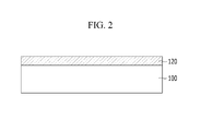
- FIG. 2 is a cross-sectional view showing the stacking structure of the heat exchanger of FIG. 1 .
- the heat exchanger includes a cooling tube 20 and a plurality of cooling fins 30, wherein a coolant passes through the cooling tube 20, and hot air, and in particular hot moist air, passes between the cooling fins 30 so that heat exchange may occur.
- the stacking structure of the heat exchanger including the cooling tube 20 and the cooling fins 30 includes a base material 100 and a surface coating layer 120 formed on the surface of the base material 100.
- the base material 100 may be formed of a metal having high thermal conductivity.
- High thermal conductivity of a metal means having a thermal conductivity of about 100 Watts per meter per Kelvin (W/m ⁇ K) or more.
- Materials having high thermal conductivities include aluminum (Al), copper (Cu), alloys thereof, and the like, or a combination comprising at least one of the foregoing, where combinations may include structural combinations such as plated structures, laminated structures, assemblies of components made from two or more different thermally conductive materials such as where a tube of one material has a vane assembly made of a different material attached thereto, or the like, or a combination comprising these structures.
- the surface coating layer 120 is coated on the surface of the base material 100.
- the surface coating layer 120 may prevent formation of frost on the surface of the base material 100, particularly when hot moist air passes through the heat exchanger.
- the surface coating layer 120 in addition to preventing the accumulation of frost, allows for frost which may accumulate to be readily removed. Removal of any frost which does accumulate may be accomplished by any known method, such as sublimation, or by mechanical removal of the frost.
- the surface coating layer 120 is described referring to FIG. 3 and FIG. 4 .
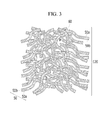
- FIG. 3 is a schematic diagram showing the surface coating layer 120 of one exemplary embodiment
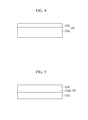
- FIG. 4 is a cross-sectional view showing one example of the stacking structure of the surface coating layer 120 of FIG. 3 .
- Stacking structure may be an ordered structure such as successive layers of the coated nanobody, an array of substructures such as regularly and irregularly shaped spheres, cylinders, plates, rods, cones, tubes, polyhedra including trigonal and tetragonal pyramids, cubes, bipyramidal structures, dodecahedrons, eicosahedrons, or the like, or any combination of these structures, arranged in a regular pattern in both the plane of the surface and perpendicular to the surface of the nanobody 50b, or may be irregularly stacked in partially random (as where the substructures are regularly arrayed in an x-y, x-z, or y-z plane but irregularly stacked in the remaining dimension, or fully random agglomeration of any of the above substructures. Interstitial spaces (i.e., pores) may be present in the layer. Combinations comprising at least one of the above substructures may be used.
- the surface coating layer 120 is formed of a composite 50 including a matrix 50a and a nanobody 50b.
- the matrix 50a may be formed of, for example, a silicon-based polymer, a fluorine-based polymer, a fluorine-substituted silicon polymer, or a combination comprising at least one of the foregoing polymers.
- the matrix 50a may be formed of a silicon-based polymer.
- Useful silicon-based polymers include polyorganosiloxanes including a siloxane repeating unit represented by the following Chemical Formula 1. Chemical Formula 1 -SiR 1 R 2 O-
- R 1 and R 2 are each independently a substituted or unsubstituted C1 to C10 alkyl group, a substituted or unsubstituted C1 to C10 heteroalkyl group, a substituted or unsubstituted C3 to C10 cycloalkyl group, a substituted or unsubstituted C2 to C10 heterocycloalkyl group, a substituted or unsubstituted C1 to C10 alkoxy group, a substituted or unsubstituted C1 to C10 heteroalkoxy group, a substituted or unsubstituted C3 to C10 cycloalkoxy group, a substituted or unsubstituted C2 to C10 heterocycloalkoxy group, a substituted or unsubstituted C2 to C10 alkenyl group, a substituted or unsubstituted C2 to C10 heteroalkenyl group, a substituted or unsubstituted C3 to C10
- the fluorine-substituted silicon polymer may include siloxane units of Chemical Formula 1 in which R 1 and R 2 are each independently fluorine, a substituted or unsubstituted C1 to C10 fluoroalkyl group, a substituted or unsubstituted C1 to C10 heterofluoroalkyl group, a substituted or unsubstituted C3 to C10 fluorocycloalkyl group, a substituted or unsubstituted C2 to C10 heterofluorocycloalkyl group, a substituted or unsubstituted C1 to C10 fluoroalkoxy group, a substituted or unsubstituted C1 to C10 heterofluoroalkoxy group, a substituted or unsubstituted C3 to C10 fluorocycloalkoxy group, a substituted or unsubstituted C2 to C10 heterofluorocycloalkoxy group, a substituted or unsubstituted C
- the siloxane repeating unit may be combined in various ways to form a cyclic, linear, or side chain structure, and the polyorganosiloxane may be a homopolymer, a copolymer, or a mixture thereof. Combinations of fluorinated and non-fluorinated siloxane repeating units may be used.
- the polyorganosiloxane may include two or more kinds of siloxane repeating units, wherein the substituent bonded to the silicon in the repeating unit represented by the above Chemical Formula 1 the same or different.
- the siloxane repeating unit may be additionally combined with mono, di, tri, tetra, penta-, hexa-, etc., alkoxy- or chlorosiloxane precursors to siloxane units to further increase the branching of the polyorganosiloxanes.
- Monomers such as, for example, tetraethylorthosilane, tetramethylorthosilane, trimethoxymethyl silane, triethoxysilane, 1.2-bis(trimethoxysilyl)ethane, and the like, or combinations thereof, may be integrated into the polysiloxane chain to form a crosslinked structure and thereby increase the mechanical stability of the polyorganosiloxanes.
- the polyorganosiloxane may include, for example, polydimethyl siloxane, polymethylphenyl siloxane, polydiphenyl siloxane, polyfluorosiloxane, polyvinylsiloxane, polyperfluorophenyl siloxane, or a combination thereof.
- the fluorine-based polymer may be any polymer having a fluorine substituent on the polymer backbone, as a substituent or pendant group, or a combination of these. Fluorine-based polymers may thus have repeating units of substituted or unsubstituted C2 to C30 fluoroalkylene groups, substituted or unsubstituted C3 to C30 fluorocycloalkylene groups, substituted or unsubstituted C6 to C30 fluoroarylene groups, substituted or unsubstituted C7 to C30 fluoroaralkylene groups, or a combination comprising at least one of the foregoing fluorinated units.
- the repeating units may be directly connected to one another by carbon-carbon bonds, carbonyl groups, or may be connected through heteroatoms such as oxygen, nitrogen, or sulfur, or combinations comprising at least one of the foregoing.
- Repeating units may, in some instances, be connected by functional groups such as ester linkages, sulfone linkages, ether linkages, sulfide linkages (thioethers), amine linkages, amide linkages, imide linkages, or the like, or combinations comprising at least one of the foregoing.
- the fluorine-based polymers may include, for example, poly(tetrafluoroethylene), poly(vinylidene fluoride), perfluoroalkoxy polymers, (perfluorodiphenyl ethers), copolymers thereof, or the like, or combinations comprising at least one of the foregoing polymers.
- the above polyorganosiloxanes and the aforementioned fluorine-based polymers may also be used to form fluorinated silicon-based polymers comprising blocks of silicon-based polymer and fluorine based polymer.
- the nanobody 50b may include, for example, nanotubes, nanofibers, nanowires, nanoparticles, nanospheres, or a combination comprising at least one of the foregoing nanobodies. More specifically, carbon nanotubes, carbon nanofibers, Si nanowire, ZnO nanowire, Cu nanowire, GaN nanowire, or a combination comprising at least one of the foregoing, may be used.
- the nanobody 50b may have at least one dimension in the nano-scale range, i.e., about 1 to less than about 1,000 nm.
- the nanobody 50b may have a diameter of, for example, about 1 nm to about 1,000 nm, and where the nanobody 50b is asymmetrical a second (length) dimension of about 0.01 ⁇ m to about 1,000 ⁇ m.
- a protrusion structure i.e., a structure having protrusions from the coated surface, may be readily formed when forming the surface coating layer.
- the composite 50 may include the nanobody 50b dispersed in the matrix 50a, and it may be formed by, for example, spray coating, dip coating, or the like, such that the matrix 50a is coated on the surface of the nanobody 50b as shown in FIG. 3 , when coating on a surface of the base material 100.
- the surface coating layer 120 may further have a mesh structure having a plurality of pores 60.
- the pores may have an average largest cross-sectional dimension (i.e., diameter) of about 1 nm to about 10 ⁇ m, where the pores are smaller than the thickness of the surface coating layer 120 or that of any sublayer.
- the surface coating layer 120 includes a lower composite layer 120a contacting a surface of the base material (not shown), and an upper composite layer 120b on, and in some exemplary embodiments, directly on and contacting, a surface of the lower composite layer 120a.
- the lower composite layer 120a and the upper composite layer 120b each has a different content by volume of the nanobody 50b.
- the nanobody 50b may be the same or different in each composite layer 120a and 120b.
- thermal conductivity and water repellency of the composite 50 may be varied according to the amount of the nanobody 50b.
- thermal conductivity of the surface coating layer 120 should be high (e.g., about 1 W/m ⁇ K or more).
- water repellency as shown by water contact angle, where high water contact angles for the surface coating layer of about 145 degrees or more, more specifically about 150 degrees or more, and still more specifically about 152 degrees or more, indicate very low wettability.
- a low sliding angle of about 8 degrees or less, specifically about 6 degrees or less, and still more specifically about 5 degrees or less also indicate low wettability, and hence, excellent water repellency.
- the thermal conductivity and water repellency of the surface coating layer 120 may be varied by adjusting the amount by volume of the nanobody 50b included in the composite 50.
- thermal conductivity and water repellency may be simultaneously improved by forming the surface coating layer 120 with a plurality of composite layers, each having a different amount of the nanobody 50b.
- the lower composite layer 120a is a part contacting the base material 100 and includes the nanobody 50b in a first amount so as to improve thermal conductivity of the surface coating layer 120.
- the lower composite layer 120a may have higher thermal conductivity than the upper composite layer 120b.
- Lower composite layer 120a may have thermal conductivity of about 1 W/m • K or more, specifically about 10 W/m ⁇ K or more, and more specifically about 25 W/m • K or more.
- the upper composite layer 120b is a part contacting the lower composite layer 120a with the opposite surface exposed to the air, and it may include the nanobody 50b in a second amount so as to increase water repellency at the air-lower composite layer 120b interface.
- FIG. 6A is a graph showing contact angle according to nanobody content by volume
- FIG. 6B is a graph showing sliding angle according to nanobody content by volume
- FIG. 7 is a graph showing thermal conductivities according to nanobody content by volume.
- contact angles and sliding angles may be varied according to nanobody content, based on volume of the composite.
- the contact angle and the sliding angle are indicative of wettability at the solid surface, wherein a higher contact angle indicates lower wettability, and hence high hydrophobicity and water repellency, and a lower sliding angle indicates lower wettability, and hence high hydrophobicity and water repellency.
- the upper composite layer 120b may include the nanobody 50b in an amount of about 12 to about 25 volume %, specifically about 15 to about 25 volume %, and more specifically about 17 to about 22 volume %, based on the total volume of the composite 50.
- the contact angle is preferably about 150° or more and the sliding angle is about 5° or less.
- the upper composite layer 120b may include the nanobody 50b in an amount of about 20 volume % based on the total volume of the composite 50.
- the lower composite layer 120a may thus include the nanobody 50b in an amount of about 30 to about 45 volume %, and specifically about 35 to about 45 volume %, based on the total volume of the composite 50 so as to have higher thermal conductivity than the upper composite layer 120b. Within the above range, the lower composite layer 120a may include the nanobody 50b in an amount of about 40 volume % based on the total volume of the composite 50.
- the lower composite layer 120a of the surface coating layer 120 which contacts the base material 100, may therefore include about 30 to 45 volume % of the nanobody 50b so as to improve thermal conductivity, and the upper composite layer 120b that contacts the air may therefore include about 15 to 25 volume % of the nanobody 50b so as to increase water repellency.
- frost on the surface i.e., on the surface coating layer
- any formed frost may be removed, by simultaneously increasing thermal conductivity and water repellency of the heat exchanger.
- FIG. 5 the stacking structure of the surface coating layer 120 according to another exemplary embodiment will be explained referring to FIG. 5 together with FIG. 2 and FIG. 3 .
- FIG. 5 is a cross-sectional view showing another example of the stacking structure of the surface coating layer 120 of FIG. 3 .
- the surface coating layer 120 includes a lower composite layer 120a and an upper composite layer 120b each having different contents by volume of the nanobody 50b, and a middle composite layer 120ab that is positioned between surfaces of the lower composite layer 120a and the upper composite layer 120b and includes the nanobody 50b with a gradually changing content, which decreases from an interface with the lower composite layer 120a to an interface with the upper composite layer 120b along a thickness dimension of the middle composite layer 120ab.
- grade changing content means a concentration gradient of the nanobody based on the volume of the composite for the middle composite layer 120ab from the interface with the lower composite layer 120a to the interface with the upper composite layer 120b, decreasing along the dimension of layer thickness from the lower composite layer 120a, to the upper composite layer 120b.
- the lower composite layer 120a and the upper composite layer 120b are as explained above.
- the middle composite layer 120ab may include the nanobody 50b with a gradually changing content by volume between the amount by volume of the nanobody 50b included in the lower composite layer 120a and the amount by volume of the nanobody 50b included in the upper composite layer 120b.
- the lower composite layer 120a, the middle composite layer 120ab, and the upper composite layer 120b are separately explained, but the amount by volume of the nanobody 50b may be continuously changed without a boundary where the amount by volume of nanobody 50b changes sharply with no apparent gradient at the interface between the lower composite layer 120a and the middle composite layer 120ab, and between the middle composite layer 120ab and the upper composite layer 120b.
- the composite 50 may further include an additive such as a cross-linking agent, a catalyst, and the like, in addition to the matrix 50a and the nanobody 50b.
- an additive such as a cross-linking agent, a catalyst, and the like, in addition to the matrix 50a and the nanobody 50b.
- the cross-linking agent may cure the surface coating layer through a cross-linking reaction with the polymer forming the matrix 50a.
- the cross-linking agent may include, for example, a silane-based compound, a SiH bond-containing organohydrosiloxane-based compound, and the like, or a combination comprising at least one of the foregoing.
- the silane-based compound may include an alkoxysilane, an aminosilane, a vinylsilane, an epoxysilane, a (meth)acrylsilane, an alkylsilane, a phenylsilane, a chlorosilane, and the like. It will be understood that, as used herein, "(meth)acryl” includes both methacryl and acryl and may represent either of these.
- SiH bond-containing organohydrogensiloxane-based compound may include pentamethyltrihydrogencyclotetrasiloxane, 1,1,3,3-tetramethyldisiloxane, 1,3,5,7-tetramethylcyclotetrasiloxane, tris(hydrogendimethylsiloxy)methylsilane, tris(hydrogendimethylsiloxy)phenylsilane, methylhydrogencyclopolysiloxane, a methylhydrogensiloxane • dimethylsiloxane cyclic copolymer, a methylhydrogenpolysiloxane including end-capping trimethylsiloxy groups at both terminal ends, a dimethylsiloxane • methylhydrogensiloxane copolymer including end-capping trimethylsiloxy groups at both terminal ends, dimethylpolysiloxane including end-capping dimethylhydrogensiloxy groups at both terminal ends, a dimethylsiloxane •
- the cross-linking agent may be included in an amount of about 1 to 200 parts by weight, specifically 10 to 100 parts by weight, based on 100 parts by weight of the matrix.
- the catalyst when included promotes a cross-linking reaction of the polymer forming the matrix 50a.
- Various metal and non-metal catalysts may be used therefor.
- the catalyst for example, tin, titanium, zirconium, lead, iron, cobalt, antimony, manganese, bismuth, zinc, alloys thereof, compounds thereof, or combinations comprising at least one of the foregoing may be used in the case that the cross-linking reaction of the polymer is a condensation type reaction.
- platinum, palladium, rhodium, alloys thereof, compounds thereof, or a combination comprising at least one of the foregoing may be used in the case that the cross-linking reaction of the polymer is an addition type reaction.
- the composite may be coated on the surface of the base material 100 and cured to form the surface coating layer 120.
- the coating may be performed, for example, by spin coating, spray coating, laminating, dip coating, flow coating, roll coating, screen printing, and the like. Since the surface coating layer 120 includes a plurality of composite layers, each having different contents by volume of the nanobody 50b as explained above, a composite layer including a first content of the nanobody 50b may be coated to a predetermined thickness, and then a composite layer including a second content of the nanobody 50b may be coated thereon to a predetermined thickness.
- the curing may be performed by thermal curing at a temperature below a deformation temperature of the base material 100, photo curing, or a combination thereof.
- the thickness of the surface coating layer 120 may be varied according to the shape and dimensions of the base material 100.
- the surface coating layer may have a thickness of about 0.5 ⁇ m to 100 ⁇ m.
- the upper composite layer 120b may have a thickness of about 100 nm to 1 ⁇ m, with the balance of the thickness of the surface coating layer met by the lower composite layer, or lower and middle composite layer combined.
- the surface coating layer 120 may have a protrusion structure wherein one end of the randomly arranged nanobody 50b protrudes outside (i.e., toward the air interface) and the shape of the surface is irregular. Such a protrusion structure may further decrease contact area of the surface coating layer 120 to water, in concert with the low slide angle and high contact angle, to further improve water repellency.
Landscapes
- Engineering & Computer Science (AREA)
- Physics & Mathematics (AREA)
- Thermal Sciences (AREA)
- Mechanical Engineering (AREA)
- General Engineering & Computer Science (AREA)
- Laminated Bodies (AREA)
Abstract
Description
- A surface coating layer and a heat exchanger including the surface coating layer are provided.
- A cooling device such as a refrigerator or a freezer lowers the temperature by repetition of the cooling cycle of compression-condensation-expansion-evaporation of a coolant, such as a fluid refrigerant which may be a liquid, gas, or a combination of these in equilibrium. The cooling device operates by increasing the temperature and pressure of the coolant from a low temperature and low pressure to a high temperature and high pressure, condensing the coolant under high temperature and high pressure by air cooling, reducing the pressure of the condensed coolant, and evaporating the coolant at reduced pressure and low pressure to absorb heat.
- The cooling device includes a heat exchanger. Since the surface temperature of the heat exchanger drops below the freezing point of water during operation, frost may form on the surface of the heat exchanger especially where hot moist air passes through the heat exchanger. The formation of frost on the heat exchanger may disturb air flow and heat transfer of the air in a cooling tube, thus decreasing heat exchange efficiency.
- In an exemplary embodiment, a surface coating layer is provided that may reduce the formation rate of frost, or that may rapidly remove formed frost to improve heat exchange efficiency.
- In another exemplary embodiment, a heat exchanger includes the surface coating layer.
- In an exemplary embodiment, a surface coating layer for a heat exchanger formed from a base material is provided, the surface coating layer comprising a plurality of composite layers comprising a first layer contacting a surface of the base material, the first layer comprising a first composite of a first matrix and a first nanobody; and a second layer contacting a surface of the first layer and having an air interface, the second layer comprising a second composite of a second matrix and a second nanobody and, wherein the first layer and the second layer each comprise a different amount by volume of the first nanobody and the second nanobody, respectively.
- The first layer may comprise the first nanobody in an amount of about 30 to about 45 volume % based on the total volume of the first composite, and the second layer may comprise the second nanobody in an amount of about 12 to about 25 volume % based on the total volume of the second composite.
- The first layer may comprise the first nanobody in an amount of about 40 volume % based on the total volume of the first composite, and the second layer may comprise the second nanobody in an amount of about 20 volume % based on the total volume of the second composite.
- The composite layer may further comprise a third layer positioned between surfaces of the first layer and the second layer, the third layer comprising a third composite comprising a third matrix and a third nanobody, the third layer having a third nanobody content by volume which gradually decreases from an interface with the first layer to an interface with the second layer along a thickness dimension of the third layer.
- The first layer may be a heat transfer layer for heat exchange from the base material to the air interface of the second layer, and the second layer may be a water-repellent layer for suppressing adherence of moisture comprised in the air.
- The first layer may have higher thermal conductivity than the second layer.
- The first layer may have thermal conductivity of about 1 W/m • K or more.
- The second layer may have a contact angle of about 145° or more and a sliding angle of about 8° or less.
- The second layer may have a thickness of about 100 nm to about 1 µm.
- The first, second, and third nanobodies may each comprise nanotubes, nanofibers, nanowire, nanoparticles, nanospheres, or a combination comprising at least one of the foregoing.
- The first, second, and third matrices may each comprise a silicon-based polymer, a fluorine-based polymer, a fluorine-substituted silicon polymer, or a combination comprising at least one of the foregoing.
- The first layer and the second layer may each have a plurality of pores.
- The surface of the second layer at the air interface may have a protrusion structure formed by the second nanobody.
- In another exemplary embodiment, a heat exchanger comprises a base material, and a surface coating layer comprising a plurality of composite layers formed on a surface of the base material, the plurality of composite layers comprising a first layer contacting a surface of the base material, the first layer comprising a first composite comprising a first matrix and a first nanobody, and a second layer contacting a surface of the first layer and having an air interface, the second layer comprising a second composite comprising a second matrix and a second nanobody, wherein the first layer and the second layer each comprise a different amount by volume of the first nanobody and the second nanobody, respectively.
- The first layer may comprise the first nanobody in an amount of about 30 to about 45 volume % based on the total volume of the first composite, and the second layer may comprise the second nanobody in an amount of about 12 to about 25 volume% based on the total volume of the second composite.
- The composite layer may further comprise a third layer positioned between surfaces of the first layer and the second layer, the third layer comprising a third composite comprising a third matrix and a third nanobody, the third layer having a third nanobody content by volume which gradually decreases from an interface with the first layer to an interface with the second layer along a thickness dimension of the third layer.
- The first layer may have thermal conductivity of about 1 W/m • K or more, and the second layer may have a contact angle of about 145° or more and a sliding angle of about 8° or less.
- The surface coating layer may have a thickness of about 0.5 µm to about 100 µm, and the second layer has a thickness of about 100 nm to about 1 µm.
- The nanobody may comprise nanotubes, nanofibers, nanowires, nanoparticles, nanospheres, or a combination comprising at least one of the foregoing, and the matrix may comprise a silicon-based polymer, a fluorine-based polymer, a fluorine-substituted silicon polymer, or a combination comprising at least one of the foregoing.
- In another exemplary embodiment, a heat exchanger is provided which comprises a base material and a surface coating layer comprising a plurality of composite layers formed on a surface of the base material, the plurality of composite layers comprising a first layer contacting the surface of the base material and having thermal conductivity of about 1 W/m • K or more, the first layer comprising a first composite comprising a first matrix and a first nanobody, and a second layer contacting a surface of the first layer and having an air interface, a contact angle of about 145° or more, and a sliding angle of about 8° or less, the second layer comprising a second composite comprising a second matrix and a second nanobody.
-
-
FIG. 1 is a schematic diagram showing a heat exchanger according to an exemplary embodiment; -
FIG. 2 is a cross-sectional view showing the stacking structure of the heat exchanger ofFIG. 1 ; -
FIG. 3 is a schematic diagram showing the surface coating layer according to an exemplary embodiment; -
FIG. 4 is a cross-sectional view showing one example of the stacking structure of the surface coating layer ofFIG. 3 ; -
FIG. 5 is a cross-sectional view showing another example of the stacking structure of the surface coating layer ofFIG. 3 ; -
FIG. 6A is a graph showing the contact angle according to the amount by volume of nanobody; -
FIG. 6B is a graph showing the sliding angle according to the amount by volume of nanobody; and -
FIG. 7 is a graph showing thermal conductivity according to the amount by volume of nanobody. - This disclosure will be described more fully hereinafter with reference to the accompanying drawings, in which exemplary embodiments are shown. This disclosure may, however, be embodied in many different forms and should not be construed as limited to the exemplary embodiments set forth herein.
- As used herein, the singular forms "a," "an" and "the" are intended to include the plural forms as well, unless the context clearly indicates otherwise. It will be further understood that the terms "comprises" and/or "comprising," when used in this specification, specify the presence of stated features, regions, integers, steps, operations, elements, and/or components, but do not preclude the presence or addition of one or more other features, regions, integers, steps, operations, elements, components, and/or groups thereof. All ranges and endpoints reciting the same feature are independently combinable.
- Unless otherwise defined, all terms (including technical and scientific terms) used herein have the same meaning as commonly understood by one of ordinary skill in the art to which this invention belongs. It will be further understood that terms, such as those defined in commonly used dictionaries, should be interpreted as having a meaning that is consistent with their meaning in the context of the relevant art and the present disclosure, and will not be interpreted in an idealized or overly formal sense unless expressly so defined herein.
- In the drawings, the thickness of layers, films, panels, regions, etc., are exaggerated for clarity. Like reference numerals designate like elements throughout the specification. It will be understood that when an element such as a layer, film, region, or substrate is referred to as being "on" another element, it can be directly on the other element or intervening elements may also be present. In contrast, when an element is referred to as being "directly on" another element, there are no intervening elements present.
- As used herein, "alkyl" refers to a straight or branched chain saturated aliphatic hydrocarbon having the specified number of carbon atoms. "Alkenyl" is a straight or branched chain hydrocarbon that comprises at least one carbon-carbon double bond. Similarly, "cycloalkyl" and "cycloalkenyl" refers to groups including a monovalent cyclic alkyl and monovalent cyclic alkenyl moiety, respectively. "Alkoxy" refers to an alkyl moiety that is linked via an oxygen (i.e., -O-alkyl). Non-limiting examples of C1 to C30 alkoxy groups include methoxy groups, ethoxy groups, propoxy groups, isobutyloxy groups, sec-butyloxy groups, pentyloxy groups, iso-amyloxy groups, hexyloxy groups, octyloxy groups, and the like. The term "alkylene" refers to a straight, branched or cyclic divalent aliphatic hydrocarbon group. The term "alkenylene" refers to a straight, branched or cyclic divalent aliphatic hydrocarbon group containing a double bond. Similarly, "cycloalkylene" and "cycloalkenylene" refers to groups including a divalent cyclic alkyl and divalent cyclic alkenyl moiety, respectively.
- As used herein "aryl," means a cyclic moiety in which all ring members are carbon and at least one ring is aromatic. More than one ring may be present, and any additional rings may be independently aromatic, saturated or partially unsaturated, and may be fused, pendant, spirocyclic or a combination thereof. As used herein, the term "arylene" refers to a divalent radical formed by the removal of two hydrogen atoms from one or more rings of an aromatic hydrocarbon, wherein the hydrogen atoms may be removed from the same or different rings (preferably different rings), each of which rings may be aromatic or nonaromatic. As used herein, "aralkyl" refers to an alkylene group in which one of the hydrogen atoms of the alkyl is replaced by an aryl group. Representative aralkyl groups include, for example, a benzyl group, a phenylethyl group, a diphenylenemethylene group, a dimethylenephenylene group, and the like. An "aralkylene" group is an aryl or arylene group linked via an alkyl or alkylene moiety. The specified number of carbon atoms (e.g., C7 to C30) refers to the total number of carbon atoms present in both the aryl and the alkylene moieties. "Aryloxy" refers to an aryl moiety that is linked via an oxygen (i.e., -O-aryl).
- A "heteroalkyl" group is an alkyl group that comprises at least one heteroatom covalently bonded to one or more carbon atoms of the alkyl group. A "heterocycloalkyl" group is a cycloalkyl group that comprises at least one heteroatom covalently bonded to one or more carbon atoms in the cycloalkyl group. A "heteroaryl" group is a monovalent carbocyclic ring system that includes one or more aromatic rings, in which at least one ring member (e.g., one, two or three ring members) is a heteroatom. For example, in a C3 to C30 heteroaryl, the total number of ring carbon atoms ranges from 3 to 30, with remaining ring atoms being heteroatoms. Multiple rings, if present, may be pendant, spiro or fused. "Heteroarylene" refers to a divalent radical formed by the removal of two hydrogen atoms from one or more rings of a heteroaryl moiety, wherein the hydrogen atoms may be removed from the same or different rings (preferably the same ring), each of which rings may be aromatic or nonaromatic. A "heteroaralkyl" group is a heteroaryl group linked via an alkylene moiety; likewise, a "heteroaralkylene" group is a heteroarylene group linked via an alkylene moiety. The specified number of carbon atoms (e.g., C3 to C30) refers to the total number of carbon atoms present in both the aryl and the alkylene moieties, with remaining ring atoms being heteroatoms as discussed above. As used herein, "combination" is inclusive of blends, mixtures, alloys, reaction products, and the like.
- As used herein, when a definition is not otherwise provided, the term "substituted" refers to one substituted with a substituent selected from a C1 to C30 alkyl group, a C2 to C30 alkynyl group, a C6 to C30 aryl group, a C7 to C30 alkylaryl group, a C1 to C4 oxyalkyl group, a C1 to C30 heteroalkyl group, a C3 to C30 heteroalkylaryl group, a C3 to C30 alicyclic group, a C3 to C15 cycloalkenyl group, a C6 to C30 cycloalkynyl group, a C2 to C30 heterocycloalkyl group, a halogen (F, Cl, Br, or l), a hydroxyl group, a C1 to C30 alkoxy group, a nitro group, a cyano group, an amino group, an azido group, an amidino group, a hydrazino group, a hydrazono group, a carbonyl group, a carbamyl group, a thiol group, an ester group, a carboxyl group or a salt thereof, a sulfonic acid or a salt thereof, phosphoric acid or a salt thereof, or a combination comprising at least one of the foregoing. Where "fluoro" is used to describe a group such as in "fluoroalkyl", "fluoroaryl", etc. it will be understood that the group contains at least one fluorine group, or may be completely fluorinated (i.e., perfluorinated). Also as used herein, where a substituent such as fluorine is disclosed or implied for a group, such as "fluoroalkyl", and "substituted" is also indicated for the group, the group contains both the disclose or implied substituent and an additional substituent not identical to the specified substituent.
- Hereinafter, a heat exchanger according to one exemplary embodiment will be described with reference to
FIG. 1 andFIG. 2 . -
FIG. 1 is a schematic diagram showing the heat exchanger according to one exemplary embodiment, andFIG. 2 is a cross-sectional view showing the stacking structure of the heat exchanger ofFIG. 1 . - Referring to
FIG. 1 , the heat exchanger according to one exemplary embodiment includes a coolingtube 20 and a plurality of coolingfins 30, wherein a coolant passes through the coolingtube 20, and hot air, and in particular hot moist air, passes between the coolingfins 30 so that heat exchange may occur. - Referring to
FIG. 2 , the stacking structure of the heat exchanger including the coolingtube 20 and the coolingfins 30 includes abase material 100 and asurface coating layer 120 formed on the surface of thebase material 100. - The
base material 100 may be formed of a metal having high thermal conductivity. High thermal conductivity of a metal, as used herein, means having a thermal conductivity of about 100 Watts per meter per Kelvin (W/m · K) or more. Materials having high thermal conductivities include aluminum (Al), copper (Cu), alloys thereof, and the like, or a combination comprising at least one of the foregoing, where combinations may include structural combinations such as plated structures, laminated structures, assemblies of components made from two or more different thermally conductive materials such as where a tube of one material has a vane assembly made of a different material attached thereto, or the like, or a combination comprising these structures.. - The
surface coating layer 120 is coated on the surface of thebase material 100. Thesurface coating layer 120 may prevent formation of frost on the surface of thebase material 100, particularly when hot moist air passes through the heat exchanger. Thesurface coating layer 120, in addition to preventing the accumulation of frost, allows for frost which may accumulate to be readily removed. Removal of any frost which does accumulate may be accomplished by any known method, such as sublimation, or by mechanical removal of the frost. - The
surface coating layer 120 is described referring toFIG. 3 andFIG. 4 . -
FIG. 3 is a schematic diagram showing thesurface coating layer 120 of one exemplary embodiment, andFIG. 4 is a cross-sectional view showing one example of the stacking structure of thesurface coating layer 120 ofFIG. 3 . - Stacking structure, as used herein, may be an ordered structure such as successive layers of the coated nanobody, an array of substructures such as regularly and irregularly shaped spheres, cylinders, plates, rods, cones, tubes, polyhedra including trigonal and tetragonal pyramids, cubes, bipyramidal structures, dodecahedrons, eicosahedrons, or the like, or any combination of these structures, arranged in a regular pattern in both the plane of the surface and perpendicular to the surface of the
nanobody 50b, or may be irregularly stacked in partially random (as where the substructures are regularly arrayed in an x-y, x-z, or y-z plane but irregularly stacked in the remaining dimension, or fully random agglomeration of any of the above substructures. Interstitial spaces (i.e., pores) may be present in the layer. Combinations comprising at least one of the above substructures may be used. - The
surface coating layer 120 is formed of a composite 50 including amatrix 50a and ananobody 50b. - The
matrix 50a may be formed of, for example, a silicon-based polymer, a fluorine-based polymer, a fluorine-substituted silicon polymer, or a combination comprising at least one of the foregoing polymers. - The
matrix 50a may be formed of a silicon-based polymer. Useful silicon-based polymers include polyorganosiloxanes including a siloxane repeating unit represented by the following Chemical Formula 1.
Chemical Formula 1 -SiR1R2O-
- In Chemical Formula 1, R1 and R2 are each independently a substituted or unsubstituted C1 to C10 alkyl group, a substituted or unsubstituted C1 to C10 heteroalkyl group, a substituted or unsubstituted C3 to C10 cycloalkyl group, a substituted or unsubstituted C2 to C10 heterocycloalkyl group, a substituted or unsubstituted C1 to C10 alkoxy group, a substituted or unsubstituted C1 to C10 heteroalkoxy group, a substituted or unsubstituted C3 to C10 cycloalkoxy group, a substituted or unsubstituted C2 to C10 heterocycloalkoxy group, a substituted or unsubstituted C2 to C10 alkenyl group, a substituted or unsubstituted C2 to C10 heteroalkenyl group, a substituted or unsubstituted C3 to C10 cycloalkenyl group, a substituted or unsubstituted C2 to C10 heterocycloalkenyl group, a substituted or unsubstituted C6 to C20 aryl group, a substituted or unsubstituted C3 to C10 heteroaryl group, a substituted or unsubstituted C6 to C20 aryloxy group, a substituted or unsubstituted C3 to C10 heteroaryloxy group, a substituted or unsubstituted C7 to C20 aralkyl group, a substituted or unsubstituted C4 to C10 heteroaralkyl group, or a combination comprising at least one of the foregoing groups.
- The fluorine-substituted silicon polymer may include siloxane units of Chemical Formula 1 in which R1 and R2 are each independently fluorine, a substituted or unsubstituted C1 to C10 fluoroalkyl group, a substituted or unsubstituted C1 to C10 heterofluoroalkyl group, a substituted or unsubstituted C3 to C10 fluorocycloalkyl group, a substituted or unsubstituted C2 to C10 heterofluorocycloalkyl group, a substituted or unsubstituted C1 to C10 fluoroalkoxy group, a substituted or unsubstituted C1 to C10 heterofluoroalkoxy group, a substituted or unsubstituted C3 to C10 fluorocycloalkoxy group, a substituted or unsubstituted C2 to C10 heterofluorocycloalkoxy group, a substituted or unsubstituted C2 to C10 fluoroalkenyl group, a substituted or unsubstituted C2 to C10 heterofluoroalkenyl group, a substituted or unsubstituted C3 to C10 fluorocycloalkenyl group, a substituted or unsubstituted C2 to C10 heterofluorocycloalkenyl group, a substituted or unsubstituted C6 to C20 fluoroaryl group, a substituted or unsubstituted C3 to C10 heterofluoroaryl group, a substituted or unsubstituted C6 to C20 fluoroaryloxy group, a substituted or unsubstituted C3 to C10 heterofluoroaryloxy group, a substituted or unsubstituted C7 to C20 fluoroaralkyl group, a substituted or unsubstituted C4 to C10 heterofluoroaralkyl group, or a combination comprising at least one of the foregoing groups.
- The siloxane repeating unit may be combined in various ways to form a cyclic, linear, or side chain structure, and the polyorganosiloxane may be a homopolymer, a copolymer, or a mixture thereof. Combinations of fluorinated and non-fluorinated siloxane repeating units may be used.
- The polyorganosiloxane may include two or more kinds of siloxane repeating units, wherein the substituent bonded to the silicon in the repeating unit represented by the above Chemical Formula 1 the same or different. The siloxane repeating unit may be additionally combined with mono, di, tri, tetra, penta-, hexa-, etc., alkoxy- or chlorosiloxane precursors to siloxane units to further increase the branching of the polyorganosiloxanes. Monomers such as, for example, tetraethylorthosilane, tetramethylorthosilane, trimethoxymethyl silane, triethoxysilane, 1.2-bis(trimethoxysilyl)ethane, and the like, or combinations thereof, may be integrated into the polysiloxane chain to form a crosslinked structure and thereby increase the mechanical stability of the polyorganosiloxanes.
- The polyorganosiloxane may include, for example, polydimethyl siloxane, polymethylphenyl siloxane, polydiphenyl siloxane, polyfluorosiloxane, polyvinylsiloxane, polyperfluorophenyl siloxane, or a combination thereof.
- The fluorine-based polymer may be any polymer having a fluorine substituent on the polymer backbone, as a substituent or pendant group, or a combination of these. Fluorine-based polymers may thus have repeating units of substituted or unsubstituted C2 to C30 fluoroalkylene groups, substituted or unsubstituted C3 to C30 fluorocycloalkylene groups, substituted or unsubstituted C6 to C30 fluoroarylene groups, substituted or unsubstituted C7 to C30 fluoroaralkylene groups, or a combination comprising at least one of the foregoing fluorinated units. The repeating units may be directly connected to one another by carbon-carbon bonds, carbonyl groups, or may be connected through heteroatoms such as oxygen, nitrogen, or sulfur, or combinations comprising at least one of the foregoing. Repeating units may, in some instances, be connected by functional groups such as ester linkages, sulfone linkages, ether linkages, sulfide linkages (thioethers), amine linkages, amide linkages, imide linkages, or the like, or combinations comprising at least one of the foregoing. The fluorine-based polymers may include, for example, poly(tetrafluoroethylene), poly(vinylidene fluoride), perfluoroalkoxy polymers, (perfluorodiphenyl ethers), copolymers thereof, or the like, or combinations comprising at least one of the foregoing polymers. The above polyorganosiloxanes and the aforementioned fluorine-based polymers may also be used to form fluorinated silicon-based polymers comprising blocks of silicon-based polymer and fluorine based polymer.
- The
nanobody 50b may include, for example, nanotubes, nanofibers, nanowires, nanoparticles, nanospheres, or a combination comprising at least one of the foregoing nanobodies. More specifically, carbon nanotubes, carbon nanofibers, Si nanowire, ZnO nanowire, Cu nanowire, GaN nanowire, or a combination comprising at least one of the foregoing, may be used. - The
nanobody 50b may have at least one dimension in the nano-scale range, i.e., about 1 to less than about 1,000 nm. Thenanobody 50b may have a diameter of, for example, about 1 nm to about 1,000 nm, and where thenanobody 50b is asymmetrical a second (length) dimension of about 0.01 µm to about 1,000 µm. When thenanobody 50b has a diameter and a length within the above ranges, dispersibility of the nanobody 50b within the matrix may be improved and a protrusion structure, i.e., a structure having protrusions from the coated surface, may be readily formed when forming the surface coating layer. - The composite 50 may include the
nanobody 50b dispersed in thematrix 50a, and it may be formed by, for example, spray coating, dip coating, or the like, such that thematrix 50a is coated on the surface of the nanobody 50b as shown inFIG. 3 , when coating on a surface of thebase material 100. - Where the
nanobody 50b is included in a predetermined amount or more, thesurface coating layer 120 may further have a mesh structure having a plurality ofpores 60. By forming such a mesh structure, stress in the structure may be reduced and durability may be increased. The pores may have an average largest cross-sectional dimension (i.e., diameter) of about 1 nm to about 10 µm, where the pores are smaller than the thickness of thesurface coating layer 120 or that of any sublayer. - Referring to
FIG. 4 , thesurface coating layer 120 includes a lowercomposite layer 120a contacting a surface of the base material (not shown), and an uppercomposite layer 120b on, and in some exemplary embodiments, directly on and contacting, a surface of the lowercomposite layer 120a. The lowercomposite layer 120a and the uppercomposite layer 120b each has a different content by volume of thenanobody 50b. Thenanobody 50b may be the same or different in eachcomposite layer - In the
surface coating layer 120, thermal conductivity and water repellency of the composite 50 may be varied according to the amount of thenanobody 50b. To reduce the formation rate of frost on the surface of the heat exchanger or to rapidly remove formed frost, thermal conductivity of thesurface coating layer 120 should be high (e.g., about 1 W/m · K or more). Simultaneously, water repellency, as shown by water contact angle, where high water contact angles for the surface coating layer of about 145 degrees or more, more specifically about 150 degrees or more, and still more specifically about 152 degrees or more, indicate very low wettability. Similarly, a low sliding angle of about 8 degrees or less, specifically about 6 degrees or less, and still more specifically about 5 degrees or less, also indicate low wettability, and hence, excellent water repellency. - The thermal conductivity and water repellency of the
surface coating layer 120 may be varied by adjusting the amount by volume of thenanobody 50b included in the composite 50. - In an exemplary embodiment, thermal conductivity and water repellency may be simultaneously improved by forming the
surface coating layer 120 with a plurality of composite layers, each having a different amount of thenanobody 50b. - Specifically, the lower
composite layer 120a is a part contacting thebase material 100 and includes the nanobody 50b in a first amount so as to improve thermal conductivity of thesurface coating layer 120. The lowercomposite layer 120a may have higher thermal conductivity than the uppercomposite layer 120b. Lowercomposite layer 120a may have thermal conductivity of about 1 W/m • K or more, specifically about 10 W/m · K or more, and more specifically about 25 W/m • K or more. - The upper
composite layer 120b is a part contacting the lowercomposite layer 120a with the opposite surface exposed to the air, and it may include thenanobody 50b in a second amount so as to increase water repellency at the air-lower composite layer 120b interface. - This is explained referring to
FIG. 6A to FIG. 7 . -
FIG. 6A is a graph showing contact angle according to nanobody content by volume,FIG. 6B is a graph showing sliding angle according to nanobody content by volume, andFIG. 7 is a graph showing thermal conductivities according to nanobody content by volume. - Referring to
FIG. 6A andFIG. 6B , it may be seen that contact angles and sliding angles may be varied according to nanobody content, based on volume of the composite. The contact angle and the sliding angle are indicative of wettability at the solid surface, wherein a higher contact angle indicates lower wettability, and hence high hydrophobicity and water repellency, and a lower sliding angle indicates lower wettability, and hence high hydrophobicity and water repellency. - Referring to
FIG. 6A andFIG. 6B , the uppercomposite layer 120b may include thenanobody 50b in an amount of about 12 to about 25 volume %, specifically about 15 to about 25 volume %, and more specifically about 17 to about 22 volume %, based on the total volume of the composite 50. The contact angle is preferably about 150° or more and the sliding angle is about 5° or less. Within the above range, the uppercomposite layer 120b may include thenanobody 50b in an amount of about 20 volume % based on the total volume of the composite 50. - Referring to
FIG. 7 , it may be seen that as the nanobody content increases, thermal conductivity increases. The lowercomposite layer 120a may thus include thenanobody 50b in an amount of about 30 to about 45 volume %, and specifically about 35 to about 45 volume %, based on the total volume of the composite 50 so as to have higher thermal conductivity than the uppercomposite layer 120b. Within the above range, the lowercomposite layer 120a may include thenanobody 50b in an amount of about 40 volume % based on the total volume of the composite 50. - As described, the lower
composite layer 120a of thesurface coating layer 120, which contacts thebase material 100, may therefore include about 30 to 45 volume % of thenanobody 50b so as to improve thermal conductivity, and the uppercomposite layer 120b that contacts the air may therefore include about 15 to 25 volume % of thenanobody 50b so as to increase water repellency. - In this way, formation of frost on the surface (i.e., on the surface coating layer) may be reduced or prevented, or any formed frost may be removed, by simultaneously increasing thermal conductivity and water repellency of the heat exchanger.
- Hereinafter, the stacking structure of the
surface coating layer 120 according to another exemplary embodiment will be explained referring toFIG. 5 together withFIG. 2 andFIG. 3 . -
FIG. 5 is a cross-sectional view showing another example of the stacking structure of thesurface coating layer 120 ofFIG. 3 . - Referring to
FIG. 5 , thesurface coating layer 120 includes a lowercomposite layer 120a and an uppercomposite layer 120b each having different contents by volume of thenanobody 50b, and a middle composite layer 120ab that is positioned between surfaces of the lowercomposite layer 120a and the uppercomposite layer 120b and includes thenanobody 50b with a gradually changing content, which decreases from an interface with the lowercomposite layer 120a to an interface with the uppercomposite layer 120b along a thickness dimension of the middle composite layer 120ab. As used herein, "gradually changing content" means a concentration gradient of the nanobody based on the volume of the composite for the middle composite layer 120ab from the interface with the lowercomposite layer 120a to the interface with the uppercomposite layer 120b, decreasing along the dimension of layer thickness from the lowercomposite layer 120a, to the uppercomposite layer 120b. - The lower
composite layer 120a and the uppercomposite layer 120b are as explained above. - The middle composite layer 120ab may include the
nanobody 50b with a gradually changing content by volume between the amount by volume of thenanobody 50b included in the lowercomposite layer 120a and the amount by volume of thenanobody 50b included in the uppercomposite layer 120b. In the drawing, for better comprehension and ease of description, the lowercomposite layer 120a, the middle composite layer 120ab, and the uppercomposite layer 120b are separately explained, but the amount by volume of thenanobody 50b may be continuously changed without a boundary where the amount by volume ofnanobody 50b changes sharply with no apparent gradient at the interface between the lowercomposite layer 120a and the middle composite layer 120ab, and between the middle composite layer 120ab and the uppercomposite layer 120b. - The composite 50 may further include an additive such as a cross-linking agent, a catalyst, and the like, in addition to the
matrix 50a and thenanobody 50b. - The cross-linking agent may cure the surface coating layer through a cross-linking reaction with the polymer forming the
matrix 50a. The cross-linking agent may include, for example, a silane-based compound, a SiH bond-containing organohydrosiloxane-based compound, and the like, or a combination comprising at least one of the foregoing. - The silane-based compound may include an alkoxysilane, an aminosilane, a vinylsilane, an epoxysilane, a (meth)acrylsilane, an alkylsilane, a phenylsilane, a chlorosilane, and the like. It will be understood that, as used herein, "(meth)acryl" includes both methacryl and acryl and may represent either of these.
- Examples of the SiH bond-containing organohydrogensiloxane-based compound may include pentamethyltrihydrogencyclotetrasiloxane, 1,1,3,3-tetramethyldisiloxane, 1,3,5,7-tetramethylcyclotetrasiloxane, tris(hydrogendimethylsiloxy)methylsilane, tris(hydrogendimethylsiloxy)phenylsilane, methylhydrogencyclopolysiloxane, a methylhydrogensiloxane • dimethylsiloxane cyclic copolymer, a methylhydrogenpolysiloxane including end-capping trimethylsiloxy groups at both terminal ends, a dimethylsiloxane • methylhydrogensiloxane copolymer including end-capping trimethylsiloxy groups at both terminal ends, dimethylpolysiloxane including end-capping dimethylhydrogensiloxy groups at both terminal ends, a dimethylsiloxane • methylhydrogensiloxane copolymer including end-capping dimethylhydrogensiloxy groups at both terminal ends, a methylhydrogensiloxane · diphenylsiloxane copolymer including end-capping trimethylsiloxy groups at both terminal ends, a methylhydrogensiloxane · diphenylsiloxane • dimethylsiloxane copolymer including end-capping trimethylsiloxy groups at both terminal ends, a methylhydrogensiloxane · methylphenylsiloxane • dimethylsiloxane copolymer including end-capping trimethylsiloxy groups at both terminal ends, a methylhydrogensiloxane • dimethylsiloxane • diphenylsiloxane copolymer including end-capping dimethylhydrogensiloxy groups at both terminal ends, a methylhydrogensiloxane • dimethylsiloxane • methylphenylsiloxane copolymer including end-capping dimethylhydrogensiloxy groups at both terminal ends, a copolymer including a (CH3)2HSiO1/2 unit, a (CH3)3SiO1/2 unit, and a SiO4/2 unit, a copolymer including a (CH3)2HSiO1/2 unit and a SiO4/2 unit, and a copolymer including a (CH3)2HSiO1/2 unit, a SiO4/2 unit, and a (C6H5)3SiO1/2 unit. Combinations comprising at least one of the foregoing units may be included.
- The cross-linking agent may be included in an amount of about 1 to 200 parts by weight, specifically 10 to 100 parts by weight, based on 100 parts by weight of the matrix.
- The catalyst when included promotes a cross-linking reaction of the polymer forming the
matrix 50a. Various metal and non-metal catalysts may be used therefor. - As the catalyst, for example, tin, titanium, zirconium, lead, iron, cobalt, antimony, manganese, bismuth, zinc, alloys thereof, compounds thereof, or combinations comprising at least one of the foregoing may be used in the case that the cross-linking reaction of the polymer is a condensation type reaction. Similarly for example platinum, palladium, rhodium, alloys thereof, compounds thereof, or a combination comprising at least one of the foregoing may be used in the case that the cross-linking reaction of the polymer is an addition type reaction.
- The composite may be coated on the surface of the
base material 100 and cured to form thesurface coating layer 120. - The coating may be performed, for example, by spin coating, spray coating, laminating, dip coating, flow coating, roll coating, screen printing, and the like. Since the
surface coating layer 120 includes a plurality of composite layers, each having different contents by volume of the nanobody 50b as explained above, a composite layer including a first content of thenanobody 50b may be coated to a predetermined thickness, and then a composite layer including a second content of thenanobody 50b may be coated thereon to a predetermined thickness. - The curing may be performed by thermal curing at a temperature below a deformation temperature of the
base material 100, photo curing, or a combination thereof. - The thickness of the
surface coating layer 120 may be varied according to the shape and dimensions of thebase material 100. The surface coating layer may have a thickness of about 0.5 µm to 100 µm. Among them, the uppercomposite layer 120b may have a thickness of about 100 nm to 1 µm, with the balance of the thickness of the surface coating layer met by the lower composite layer, or lower and middle composite layer combined. - The
surface coating layer 120 may have a protrusion structure wherein one end of the randomly arrangednanobody 50b protrudes outside (i.e., toward the air interface) and the shape of the surface is irregular. Such a protrusion structure may further decrease contact area of thesurface coating layer 120 to water, in concert with the low slide angle and high contact angle, to further improve water repellency. - While this invention has been described in connection with what is presently considered to be practical exemplary embodiments, it is to be understood that the invention is not limited to the disclosed embodiments, but, on the contrary, is intended to cover various modifications and equivalent arrangements included within the scope of the appended claims.
Claims (15)
- A surface coating layer for a heat exchanger formed of a base material, the surface coating layer comprising:a plurality of composite layers comprising;
a first layer contacting a surface of the base material, the first layer comprising:a first composite, comprising:a second layer contacting a surface of the first layer and having an air interface, the second layer comprising:a first matrix, anda first nanobody; anda second composite, comprising:a second matrix, anda second nanobody;wherein the first layer and the second layer each comprise a different amount by volume of the first nanobody and the second nanobody, respectively. - The surface coating layer of claim 1, wherein the first layer comprises the first nanobody in an amount of about 30 to about 45 volume %, based on the total volume of the first composite, and
the second layer comprises the second nanobody in an amount of about 12 to about 25 volume %, based on the total volume of the second composite. - The surface coating layer of claim 2, wherein the first layer comprises the first nanobody in an amount of about 40 volume %, based on the total volume of the first composite, and
the second layer comprises the second nanobody in an amount of about 20 volume %, based on the total volume of the second composite. - The surface coating layer of any of claims 1-3, wherein the composite layer further comprises:a third layer positioned between surfaces of the first layer and the second layer, the third layer comprising;a third composite, comprising
a third matrix, and
a third nanobody,the third layer having a third nanobody content by volume which gradually decreases from an interface with the first layer to an interface with the second layer along a thickness dimension of the third layer. - The surface coating layer of any of claims 1-4, wherein the first layer is a heat transfer layer for heat exchange from the base material to the air interface of the second layer, and
the second layer is a water-repellent layer for suppressing adherence of moisture included in the air. - The surface coating layer of any of claims 1-5, wherein the first layer has higher thermal conductivity than the second layer.
- The surface coating layer of any of claims 1-6, wherein the first layer has a thermal conductivity of about 1 W/m • K or more.
- The surface coating layer of any of claims 1-7, wherein the second layer has a contact angle of about 145° or more and a sliding angle of about 8° or less.
- The surface coating layer of any of claims 1-8, wherein the second layer has a thickness of about 100 nm to about 1 µm.
- The surface coating layer of any of claims 1-9, wherein the first nanobody and second nanobody each comprise nanotubes, nanofibers, nanowire, nanoparticles, nanospheres, or a combination comprising at least one of the foregoing.
- The surface coating layer of any of claims 1-10, wherein the first matrix and second matrix each comprise a silicon-based polymer, a fluorine-based polymer, a fluorine-substituted silicon polymer, or a combination comprising at least one of the foregoing.
- The surface coating layer of any of claims 1-11, wherein the first layer and the second layer each have a plurality of pores.
- The surface coating layer of any of claims 1-12, wherein a surface of the second layer at the air interface has a protrusion structure formed by the second nanobody.
- A heat exchanger, comprising:a base material; anda surface coating layer according to any of claims 1-13 formed on a surface of the base material.
- A heat exchanger, comprising:a base material, anda surface coating layer, comprising:a plurality of composite layers formed on a surface of the base material, the plurality of composite layers comprising:a first layer contacting the surface of the base material, and having thermal conductivity of about 1 W/m • K or more, the first layer comprising:a first composite, comprising:a first matrix, anda first nanobody; anda second layer contacting a surface of the first layer and having an air interface, a contact angle of about 145° or more, and a sliding angle of about 8° or less, the second layer comprising:a second composite, comprising:a second matrix, anda second nanobody.
Applications Claiming Priority (1)
| Application Number | Priority Date | Filing Date | Title |
|---|---|---|---|
| KR1020110003676A KR20120082278A (en) | 2011-01-13 | 2011-01-13 | Surface coating layer and heat exchanger including the surface coating layer |
Publications (2)
| Publication Number | Publication Date |
|---|---|
| EP2476990A2 true EP2476990A2 (en) | 2012-07-18 |
| EP2476990A3 EP2476990A3 (en) | 2014-11-12 |
Family
ID=45062915
Family Applications (1)
| Application Number | Title | Priority Date | Filing Date |
|---|---|---|---|
| EP11188790.7A Withdrawn EP2476990A3 (en) | 2011-01-13 | 2011-11-11 | Surface coating layer and heat exchanger including the surface coating layer |
Country Status (4)
| Country | Link |
|---|---|
| US (1) | US20120181004A1 (en) |
| EP (1) | EP2476990A3 (en) |
| KR (1) | KR20120082278A (en) |
| CN (1) | CN102615866A (en) |
Cited By (4)
| Publication number | Priority date | Publication date | Assignee | Title |
|---|---|---|---|---|
| EP2829835A1 (en) * | 2013-07-23 | 2015-01-28 | LG Electronics, Inc. | Heat exchanger and method and apparatus for manufacturing the same |
| WO2015104233A1 (en) * | 2014-01-13 | 2015-07-16 | Siemens Aktiengesellschaft | Device for transferring heat between at least two material flows present at different temperatures |
| WO2016019303A1 (en) * | 2014-07-31 | 2016-02-04 | Carrier Corporation | Coated heat exchanger |
| JP2018155483A (en) * | 2017-03-15 | 2018-10-04 | ドゥサン ヘヴィー インダストリーズ アンド コンストラクション カンパニー リミテッド | Heat transfer pipe with ultra water repellent surface, and manufacturing method thereof |
Families Citing this family (8)
| Publication number | Priority date | Publication date | Assignee | Title |
|---|---|---|---|---|
| JP5619295B2 (en) * | 2011-10-03 | 2014-11-05 | 三菱電機株式会社 | Refrigeration cycle equipment |
| CN103697750A (en) * | 2012-12-29 | 2014-04-02 | 摩尔动力(北京)技术股份有限公司 | Anti-frost cooling unit |
| CN103697751B (en) * | 2013-12-11 | 2017-01-25 | 上海交通大学 | Surface coating for heat exchanger and surface treatment method for heat exchanger |
| FR3034805B1 (en) | 2015-04-10 | 2019-06-14 | Calyf | DRILLING METHOD, METHOD OF MAKING A PRESSIOMETRIC TEST, CORRESPONDING ASSEMBLY |
| KR101987699B1 (en) * | 2017-03-17 | 2019-06-11 | 엘지전자 주식회사 | Heat exchanger |
| US20190107343A1 (en) * | 2017-10-09 | 2019-04-11 | Hamilton Sundstrand Corporation | Functionally graded composite polymer for heat exchanger |
| SG11202010267PA (en) * | 2018-05-10 | 2020-11-27 | Nelumbo Inc | Phase change barriers and methods of use thereof |
| JP7435978B2 (en) * | 2020-07-20 | 2024-02-21 | 国立大学法人京都大学 | Heat exchanger and refrigeration cycle equipment |
Family Cites Families (13)
| Publication number | Priority date | Publication date | Assignee | Title |
|---|---|---|---|---|
| JPH07251130A (en) * | 1994-03-11 | 1995-10-03 | Kansai Paint Co Ltd | Formation of water-repellent coating film |
| US20050257558A1 (en) * | 2002-11-26 | 2005-11-24 | Daikin Industries, Ltd. | Heat exchanger for air and freezer device |
| US7985475B2 (en) * | 2003-04-28 | 2011-07-26 | Nanosys, Inc. | Super-hydrophobic surfaces, methods of their construction and uses therefor |
| DE10355833A1 (en) * | 2003-11-26 | 2005-06-23 | Behr Gmbh & Co. Kg | heat exchangers |
| JP4464796B2 (en) * | 2004-11-15 | 2010-05-19 | 日立アプライアンス株式会社 | Heat exchanger and manufacturing method thereof |
| US20060216476A1 (en) * | 2005-03-28 | 2006-09-28 | General Electric Company | Articles having a surface with low wettability and method of making |
| CN2937999Y (en) * | 2006-08-15 | 2007-08-22 | 中国石油天然气集团公司 | Heat exchanger with modified surface modified coating |
| TWI374922B (en) * | 2006-12-29 | 2012-10-21 | Eternal Chemical Co Ltd | Anti-uv coating composition and the use thereof |
| EP2117836B1 (en) * | 2007-02-22 | 2012-11-07 | Dow Corning Corporation | Reinforced silicone resin films |
| JP5250025B2 (en) * | 2007-05-01 | 2013-07-31 | ダウ・コーニング・コーポレイション | Reinforced silicone resin film |
| US8261961B2 (en) * | 2008-04-10 | 2012-09-11 | Lockheed Martin Corporation | Metal matrix carbon nanotube composite material and method of making same |
| DE602008006375D1 (en) * | 2008-06-05 | 2011-06-01 | Iguzzini Illuminazione | Double coating, its preparation and its use for applying highly water-repellent and non-reflective layers on surfaces |
| DE102009024802B3 (en) * | 2009-05-29 | 2010-07-08 | Siemens Aktiengesellschaft | Use of a ceramic layer and method for producing such a layer |
-
2011
- 2011-01-13 KR KR1020110003676A patent/KR20120082278A/en not_active Ceased
- 2011-05-17 US US13/109,559 patent/US20120181004A1/en not_active Abandoned
- 2011-11-11 EP EP11188790.7A patent/EP2476990A3/en not_active Withdrawn
-
2012
- 2012-01-13 CN CN201210010323XA patent/CN102615866A/en active Pending
Non-Patent Citations (1)
| Title |
|---|
| None |
Cited By (7)
| Publication number | Priority date | Publication date | Assignee | Title |
|---|---|---|---|---|
| EP2829835A1 (en) * | 2013-07-23 | 2015-01-28 | LG Electronics, Inc. | Heat exchanger and method and apparatus for manufacturing the same |
| WO2015104233A1 (en) * | 2014-01-13 | 2015-07-16 | Siemens Aktiengesellschaft | Device for transferring heat between at least two material flows present at different temperatures |
| WO2016019303A1 (en) * | 2014-07-31 | 2016-02-04 | Carrier Corporation | Coated heat exchanger |
| US10760858B2 (en) | 2014-07-31 | 2020-09-01 | Carrier Corporation | Coated heat exchanger |
| JP2018155483A (en) * | 2017-03-15 | 2018-10-04 | ドゥサン ヘヴィー インダストリーズ アンド コンストラクション カンパニー リミテッド | Heat transfer pipe with ultra water repellent surface, and manufacturing method thereof |
| EP3399233A1 (en) * | 2017-03-15 | 2018-11-07 | Doosan Heavy Industries & Construction Co., Ltd. | Method for manufacturing a heat transfer tube comprising a superhydrophobic surface |
| US10663237B2 (en) | 2017-03-15 | 2020-05-26 | Doosan Heavy Industries Construction Co., Ltd. | Heat transfer tube having superhydrophobic surface and method for manufacturing the same |
Also Published As
| Publication number | Publication date |
|---|---|
| KR20120082278A (en) | 2012-07-23 |
| CN102615866A (en) | 2012-08-01 |
| US20120181004A1 (en) | 2012-07-19 |
| EP2476990A3 (en) | 2014-11-12 |
Similar Documents
| Publication | Publication Date | Title |
|---|---|---|
| US20120181004A1 (en) | Surface coating layer and heat exchanger including the surface coating layer | |
| JP5867325B2 (en) | Method for producing water-repellent substrate | |
| EP2536561B1 (en) | Nano-coatings for articles | |
| US20150368824A1 (en) | Water and oil ultra-repellent structure and manufacturing method therefor | |
| US20120111549A1 (en) | Heat transport fluid passage device with hydrophobic membrane | |
| US20170015842A1 (en) | Water/oil repellant coating film and manufacturing method thereof | |
| KR20090115794A (en) | Method for producing a conductive film and articles made using the method | |
| WO2015164632A1 (en) | Managing condensation with angled fluid control features | |
| CN101779280B (en) | Corrugated interfaces for multilayered interconnects | |
| KR101492823B1 (en) | Water Harvester Having Micro-line Pattern | |
| Patil et al. | Facile Approach for Designing Icephobic Coatings Using Polymers/Silica Nanoparticle Composites via Self‐Formation of Superhydrophobic Surfaces | |
| JP7031790B2 (en) | Structures, manufacturing methods for structures, heat exchanger members and heat exchangers | |
| JP2008094870A5 (en) | ||
| KR101510304B1 (en) | Hybrid heat conductable pin with hydrophilic and hydrophobic characteristics and method thereof | |
| JP2004294049A (en) | Heat exchanger and refrigeration system for air | |
| TWI489225B (en) | Intermediate transfer belt and manufacturing method thereof | |
| JP2011094873A5 (en) | ||
| JP6061239B2 (en) | Flame retardant imparting agent, flame retardant article and method for producing them | |
| JP2834228B2 (en) | Water repellent coating composition and heat exchanger using the water repellent coating composition | |
| EP3549750A1 (en) | Heat resistant composite sheet and manufacturing method therefor | |
| US11840013B2 (en) | Graphite materials and devices with surface micro-texturing | |
| CN101365990B (en) | Intermediate transfer belt and manufacturing method thereof | |
| CN1103904C (en) | Outdoor heat exchanger unit and air-conditioner using the unit | |
| JP2584109B2 (en) | Paint for water-repellent coating and heat exchanger coated with the paint | |
| JP2017037762A (en) | Ion exchange membrane, battery and method for producing the same |
Legal Events
| Date | Code | Title | Description |
|---|---|---|---|
| PUAI | Public reference made under article 153(3) epc to a published international application that has entered the european phase |
Free format text: ORIGINAL CODE: 0009012 |
|
| 17P | Request for examination filed |
Effective date: 20120330 |
|
| AK | Designated contracting states |
Kind code of ref document: A2 Designated state(s): AL AT BE BG CH CY CZ DE DK EE ES FI FR GB GR HR HU IE IS IT LI LT LU LV MC MK MT NL NO PL PT RO RS SE SI SK SM TR |
|
| AX | Request for extension of the european patent |
Extension state: BA ME |
|
| RAP1 | Party data changed (applicant data changed or rights of an application transferred) |
Owner name: SAMSUNG ELECTRONICS CO., LTD. |
|
| PUAL | Search report despatched |
Free format text: ORIGINAL CODE: 0009013 |
|
| AK | Designated contracting states |
Kind code of ref document: A3 Designated state(s): AL AT BE BG CH CY CZ DE DK EE ES FI FR GB GR HR HU IE IS IT LI LT LU LV MC MK MT NL NO PL PT RO RS SE SI SK SM TR |
|
| AX | Request for extension of the european patent |
Extension state: BA ME |
|
| RIC1 | Information provided on ipc code assigned before grant |
Ipc: F28F 19/00 20060101ALI20141007BHEP Ipc: F28F 17/00 20060101AFI20141007BHEP |
|
| STAA | Information on the status of an ep patent application or granted ep patent |
Free format text: STATUS: THE APPLICATION IS DEEMED TO BE WITHDRAWN |
|
| 18D | Application deemed to be withdrawn |
Effective date: 20170601 |