EP2476925A1 - Rolling bearing cage partly consisting of composite material reinforced by filaments - Google Patents
Rolling bearing cage partly consisting of composite material reinforced by filaments Download PDFInfo
- Publication number
- EP2476925A1 EP2476925A1 EP20110150759 EP11150759A EP2476925A1 EP 2476925 A1 EP2476925 A1 EP 2476925A1 EP 20110150759 EP20110150759 EP 20110150759 EP 11150759 A EP11150759 A EP 11150759A EP 2476925 A1 EP2476925 A1 EP 2476925A1
- Authority
- EP
- European Patent Office
- Prior art keywords
- plastic
- fiber composite
- fibers
- rolling element
- section
- Prior art date
- Legal status (The legal status is an assumption and is not a legal conclusion. Google has not performed a legal analysis and makes no representation as to the accuracy of the status listed.)
- Withdrawn
Links
Images

Classifications
-
- F—MECHANICAL ENGINEERING; LIGHTING; HEATING; WEAPONS; BLASTING
- F16—ENGINEERING ELEMENTS AND UNITS; GENERAL MEASURES FOR PRODUCING AND MAINTAINING EFFECTIVE FUNCTIONING OF MACHINES OR INSTALLATIONS; THERMAL INSULATION IN GENERAL
- F16C—SHAFTS; FLEXIBLE SHAFTS; ELEMENTS OR CRANKSHAFT MECHANISMS; ROTARY BODIES OTHER THAN GEARING ELEMENTS; BEARINGS
- F16C33/00—Parts of bearings; Special methods for making bearings or parts thereof
- F16C33/30—Parts of ball or roller bearings
- F16C33/38—Ball cages
- F16C33/3825—Ball cages formed as a flexible belt, e.g. spacers connected by a thin film
-
- F—MECHANICAL ENGINEERING; LIGHTING; HEATING; WEAPONS; BLASTING
- F16—ENGINEERING ELEMENTS AND UNITS; GENERAL MEASURES FOR PRODUCING AND MAINTAINING EFFECTIVE FUNCTIONING OF MACHINES OR INSTALLATIONS; THERMAL INSULATION IN GENERAL
- F16C—SHAFTS; FLEXIBLE SHAFTS; ELEMENTS OR CRANKSHAFT MECHANISMS; ROTARY BODIES OTHER THAN GEARING ELEMENTS; BEARINGS
- F16C33/00—Parts of bearings; Special methods for making bearings or parts thereof
- F16C33/30—Parts of ball or roller bearings
- F16C33/38—Ball cages
- F16C33/3831—Ball cages with hybrid structure, i.e. with parts made of distinct materials
-
- F—MECHANICAL ENGINEERING; LIGHTING; HEATING; WEAPONS; BLASTING
- F16—ENGINEERING ELEMENTS AND UNITS; GENERAL MEASURES FOR PRODUCING AND MAINTAINING EFFECTIVE FUNCTIONING OF MACHINES OR INSTALLATIONS; THERMAL INSULATION IN GENERAL
- F16C—SHAFTS; FLEXIBLE SHAFTS; ELEMENTS OR CRANKSHAFT MECHANISMS; ROTARY BODIES OTHER THAN GEARING ELEMENTS; BEARINGS
- F16C33/00—Parts of bearings; Special methods for making bearings or parts thereof
- F16C33/30—Parts of ball or roller bearings
- F16C33/38—Ball cages
- F16C33/44—Selection of substances
-
- F—MECHANICAL ENGINEERING; LIGHTING; HEATING; WEAPONS; BLASTING
- F16—ENGINEERING ELEMENTS AND UNITS; GENERAL MEASURES FOR PRODUCING AND MAINTAINING EFFECTIVE FUNCTIONING OF MACHINES OR INSTALLATIONS; THERMAL INSULATION IN GENERAL
- F16C—SHAFTS; FLEXIBLE SHAFTS; ELEMENTS OR CRANKSHAFT MECHANISMS; ROTARY BODIES OTHER THAN GEARING ELEMENTS; BEARINGS
- F16C2208/00—Plastics; Synthetic resins, e.g. rubbers
- F16C2208/80—Thermosetting resins
- F16C2208/82—Composites, i.e. fibre reinforced thermosetting resins
-
- F—MECHANICAL ENGINEERING; LIGHTING; HEATING; WEAPONS; BLASTING
- F16—ENGINEERING ELEMENTS AND UNITS; GENERAL MEASURES FOR PRODUCING AND MAINTAINING EFFECTIVE FUNCTIONING OF MACHINES OR INSTALLATIONS; THERMAL INSULATION IN GENERAL
- F16C—SHAFTS; FLEXIBLE SHAFTS; ELEMENTS OR CRANKSHAFT MECHANISMS; ROTARY BODIES OTHER THAN GEARING ELEMENTS; BEARINGS
- F16C2220/00—Shaping
- F16C2220/02—Shaping by casting
- F16C2220/04—Shaping by casting by injection-moulding
-
- F—MECHANICAL ENGINEERING; LIGHTING; HEATING; WEAPONS; BLASTING
- F16—ENGINEERING ELEMENTS AND UNITS; GENERAL MEASURES FOR PRODUCING AND MAINTAINING EFFECTIVE FUNCTIONING OF MACHINES OR INSTALLATIONS; THERMAL INSULATION IN GENERAL
- F16C—SHAFTS; FLEXIBLE SHAFTS; ELEMENTS OR CRANKSHAFT MECHANISMS; ROTARY BODIES OTHER THAN GEARING ELEMENTS; BEARINGS
- F16C2300/00—Application independent of particular apparatuses
- F16C2300/10—Application independent of particular apparatuses related to size
- F16C2300/14—Large applications, e.g. bearings having an inner diameter exceeding 500 mm
-
- F—MECHANICAL ENGINEERING; LIGHTING; HEATING; WEAPONS; BLASTING
- F16—ENGINEERING ELEMENTS AND UNITS; GENERAL MEASURES FOR PRODUCING AND MAINTAINING EFFECTIVE FUNCTIONING OF MACHINES OR INSTALLATIONS; THERMAL INSULATION IN GENERAL
- F16C—SHAFTS; FLEXIBLE SHAFTS; ELEMENTS OR CRANKSHAFT MECHANISMS; ROTARY BODIES OTHER THAN GEARING ELEMENTS; BEARINGS
- F16C2340/00—Apparatus for treating textiles
Definitions
- the invention relates to a WälzMechhimfig for rolling bearings.
- Rolling bearings basically include a number of rolling elements, which are held in at least in some applications in a rolling bearing cage. This has the task to distance the rolling elements and to prevent their mutual contact.
- the cage made of metal or plastic material.
- the DE 103 51 346 to construct the rolling bearing cage of a matrix, for example of epoxy resin, in which a reinforcement in the form of a woven or nonwoven fabric made of polyamide fibers is embedded.
- the fibers serve to provide emergency running properties, which is based on their choice of material.
- the fibers can absorb, for example, lubricant.
- the DE 10 2004 058 518 A1 also proposes a roller bearing cage made of a composite material.
- the plastic is provided with an additive to reduce the coefficient of friction.
- a solid lubricant such as a fluoropolymer is proposed.
- the DE 10 2008 027 764 A1 proposes rolling bearing cages made of epoxy resin and ramie fibers for the construction of particularly high-speed bearings. These are linen-like bast fibers that help lessen the friction and to absorb oil.
- beats JP 2006-300257 A a rolling bearing with a cage, which consists of a composite material.
- This composite material is formed by a resin matrix with embedded carbon nanotubes. These have a very good thermal conductivity, which is used for the storage cooling.
- the method of claim 15 allows the production of a rolling bearing cage that meets the requirements set.
- the rolling element cage according to the invention has at least one, preferably a plurality of fiber composite sections, which consist of a fiber-reinforced plastic material. Furthermore, there are at least one plastic section, preferably a plurality of plastic sections, which are connected to the fiber composite section.
- the fiber composite portion may be elongated and arranged to extend in the longitudinal direction of the rolling element cage.
- the longitudinal direction is defined by the series of successively arranged rolling elements.
- the plastic portion may be formed so that it is firmly connected to the fiber composite portion or at least partially envelops or surrounds.
- the plastic sections may form webs which engage between the rolling elements. Between the plastic sections recesses may be formed, in which sit the rolling elements. It is possible to limit these recesses or pockets in the longitudinal direction by the plastic sections while they are limited in the lateral direction of the fiber composite sections.
- the Hauptreiblast exists between the plastic sections and the Rolling elements.
- the rolling elements and the plastic sections can touch.
- the plastic sections can be optimally matched to this task with regard to the choice of material.
- a fiber-free plastic can be used.
- plastics that form a favorable friction pairing with the rolling elements may be chosen.
- the plastic body may be filled with friction-reducing particles. These particles may be in the form of grains, tinsel or even fibers. It can be natural fibers or synthetic fibers.
- the plastic of the plastic sections may have emergency lubricating properties and may be filled with liquid and / or solid lubricants, for example graphite, talc or the like.
- the fiber composite section can be optimized in terms of other properties than the plastic section.
- the fiber composite portion may be optimized in terms of thermal linear expansion coefficient or expansion due to exposure to moisture.
- fibers for the fiber composite section mineral fibers, glass fibers, carbon fibers or the like can be used. With carbon fibers, a particularly low thermal expansion coefficient can be achieved. Because of the existing distance between the rolling elements and the fiber composite sections abrasive wear of the rolling elements can be minimized or prevented.
- the fibers are oriented in the longitudinal direction of the Wälz stressesmaschinefigs.
- the fibers are preferably embedded in a plastic matrix. It can find fiber mixtures application, whereby also fibers with the plastic the plastic matrix welded or glued, can be provided. It is also possible to provide fibers of a plastic which coincides with the plastic of the matrix, so that an optimal wrapping and wrapping of the other fibers of the fiber mixture takes place.
- endless fibers are used as fibers, these are fibers whose length is greater than the circumference of the bearing or its length. If it is a linear bearing. Preferably, the length of such a "continuous fiber" exceeds a multiple of the bearing circumference or the bearing length.
- the WälzMechchankafig can be designed as a linear cage for linear bearings, as a linear cage, which is formed into a ring in use or as a closed ring.
- the fiber composite section is produced in continuous production as a linear element, which is then provided in sections or in continuous production with the plastic sections.
- the cross-section of the fiber composite section may be round, square, rectangular or otherwise shaped. In particular, it is possible to form the fiber composite section in the form of a band.
- the plastic sections are preferably shaped so that they play around the rolling elements between each other, i. form matching pockets.
- the plastic portions are formed so that the rolling elements are held captive locked in the Wälz Eisenfig.
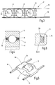
- FIG. 1 a linear roller bearing 10 is illustrated which has two raceways 11, 12. Between these rolling elements 13, 14, 15, 16 are arranged to support a raceway 12 rolling on the other raceway 11.
- the rolling elements 13-16 are balls in the present embodiment.
- the rolling elements 13 - 16 may also have other suitable shapes, such as cylindrical shape, barrel shape, truncated cone shape, needle shape or any other shape suitable for rolling elements.
- the rolling elements 13 - 16 (and other rolling elements, not shown) are held in a rolling element cage 17.
- This comprises at least one, preferably two fiber composite sections 18, 19 extending along the row formed by the rolling elements 13, 14, 15 and so on.
- FIG. 3 illustrates this.
- the two fiber composite sections 18, 19 may have a rectangular cross section, as it FIGS. 4 to 6 demonstrate. But you can also other cross-sectional shapes, such as round, oval, rectangular, triangular, polygonal o.ä. exhibit.
- the two elongated fiber composite sections 18, 19 preferably extend parallel to each other on both sides of the row of rolling elements 13, 14, 15, 16.
- the cross section of the fiber composite sections 18, 19 is preferably unchanged along the length thereof. He can also change, if so desired.
- the WälzMechshifig 17 has at least one but preferably a number of plastic sections 20 - 24, between the rolling elements 13, 14, 15, grab and keep them at a distance (see FIG. 1 and 3 ). Also, the plastic sections two or, for example, multi-row bearings, several fiber composite sections 18, 19 interconnect.
- the plastic sections 20 - 24 are preferably made of a plastic with respect to the sliding properties and wear properties optimized, such as epoxy resin or preferably a thermoplastic, processable by injection molding or transfer molding process plastic.
- This plastic can be designed as a homogeneous mass. It may also contain embeddings such as particles, platelets, fibers, bubbles, droplets or the like. These embeddings are preferably selected for optimizing slip properties and wear properties. It may be natural fibers or synthetic fibers, graphite particles, oil or similar. act.
- the fiber composite sections 18, 19 preferably contain particularly high tensile strength fibers with low temperature and moisture expansion coefficients, such as glass fibers or in particular aramid or carbon fibers. These each extend in the longitudinal direction of the respective plastic section.
- the fibers can be incorporated into the plastic matrix of the respective fiber composite section 18, 19 as straight fibers, for example as rovings or twisted or untwisted filament yarns. Stranded or twisted fibers may also be used. It can find fiber mixtures of different fibers and / or fiber materials application. For example, their blend can be tuned to provide a coefficient of expansion for the fiber composite section that matches, for example, that of the raceways 11, 12 (e.g., steel).
- the fiber composite sections 18, 19 have a plastic matrix whose plastic is compatible with the plastic of the plastic sections 20-24.
- the plastics of the plastic sections 20 - 24 and the fiber composite sections 18, 19 glued together or be welded. If the plastic sections 20-24 are produced by the plastic injection method, the plastic sections 20-24 are preferably fused to the plastic of the fiber composite sections 18, 19.
- FIG. 6 shows such a situation.
- the plastic portion 21 engages around the fiber composite section 19.
- the plastic material of the fiber composite section 19 is fused, welded or glued to the plastic material of the plastic section. They are thus materially interconnected. In addition, they can be positively connected to each other by the mentioned encompassing.
- FIG. 6 also shows the fibers 19a provided in the fiber composite section.
- fibers and / or mineral fibers may be organic fibers and / or mineral fibers, in particular glass fibers, carbon fibers or the like.
- a fiber mixture can also be provided.
- the fiber mixture can contain plastic fibers made of a plastic which coincides with the plastic of the surrounding plastic matrix or is compatible with it insofar as it can thermally bond or fuse with it.
- seam surface 19/21 is also possible to form the seam surface 19/21 as an interface without material connection between the plastic materials of the fiber composite portion 19 and the plastic portion 21.
- the two sections are then only positively connected to each other.
- FIG. 3 shows, the fiber composite sections 18, 19 between adjacent plastic sections 21, 22 are exposed.
- the plastic portions 21, 22 are provided with concave end faces and shaped so that they locked between each other, the respective rolling elements 14 and thus hold captive.
- FIG. 1 illustrates wings formed on the plastic portion 22 25-28, which cling to the adjacent balls 14, 15 and thereby secure. Two adjacent plastic sections each define pockets between each other into which the respective rolling bodies 13 - 16 can be engaged and disengaged.
- plastic portions 29 are provided, each having a pocket 30 for latching receiving a rolling element, such as the ball 13, have. At its end faces, the plastic portion 29 may be formed concavely curved to form a contact surface 31 for another rolling element. In a corresponding row of a plurality of bodies 29 arranged on the fiber composite sections 18, 19, the balls or other rolling elements can then be alternately held in a pocket of a section 29 and between two such sections.
- each plastic section 29 holds its own rolling elements.
- the fiber composite sections 18, 19 a strip-shaped plastic section having a series of pockets for receiving the rolling elements.
- the bags can again according to the embodiment according to FIG. 1 the individual rolling elements 13, 14, 15, etc. hold locked captive.
- FIG. 2 and 4 an embodiment of a rolling bearing 10 is illustrated for the rotational mounting of a machine part, in which the rolling element cage 17 according to the invention is annular.
- the fiber composite sections 18, 19 are formed as closed rings. They in turn have plastic sections 20 - 24, between which are mounted as rolling elements 13 - 16, for example, balls. The number of rolling elements is set so that a complete ring of rolling elements results around the inner race 11 around.
- the fiber composite sections 18, 19 may be formed as open rings or as closed rings, ie, endless rings. Otherwise applies with regard to the formation of the fiber composite sections 18, 19, as well as the plastic section 20 - 24, the above description ofcollectsmögichkeiten- forms and forms accordingly.
- the rolling element cage 17 has a thermal expansion coefficient in the longitudinal direction, which is determined by the fiber composite sections 18, 19.
- fiber for example a mixture of glass fibers and / or carbon fibers
- the raceways 11, 12 are preferably made of steel.
- the bearing can be formed very low backlash and rolling elements, such as balls, have, whose diameter is very small in relation to the bearing diameter, for example, less than 5%, 3% or even 1% of the same.
- the adaptation of the coefficient of thermal expansion of the rolling element cage 17 to the thermal expansion coefficients of the raceways 11, 12 ensures a low-wear clamping-free running. This also applies to expansion or shrinkage due to moisture.
- the fiber composite sections may be formed to have little wet conditional expansion.
- the production of the roller cage 17 is preferably carried out at least two stages.
- the fiber composite sections 18, 19 are provided.
- the plastic sections 21 - 24 and / or 29 are attached.
- the latter can be done by spraying, ie prototypes, or, if necessary, by assembly measures, which include prefabrication and gluing and / or welding.
- the WälzMechchanshifig invention consists of at least two different materials, namely on the one hand a fiber composite material and on the other hand of a plastic containing no or other fibers.
- the fiber composite sections 18, 19 preferably have continuous fibers. If the plastic sections contain fibers, these are preferably short fibers. When the fibers accommodated in the fiber composite parts are abrasive, such fibers are preferably absent in the plastic sections.
- the rolling element cages 17 according to the invention are set up for a low-wear operation in a wide temperature range.
Abstract
Description
Die Erfindung betrifft einen Wälzkörperkäfig für Wälzlager.The invention relates to a Wälzkörperkäfig for rolling bearings.
Wälzlager umfassen grundsätzlich eine Anzahl von Wälzkörpern, die zumindest bei einigen Anwendungsfällen in einem Wälzlagerkäfig gehalten sind. Dieser hat die Aufgabe, die Wälzkörper zu distanzieren und deren gegenseitige Berührung zu verhindern.Rolling bearings basically include a number of rolling elements, which are held in at least in some applications in a rolling bearing cage. This has the task to distance the rolling elements and to prevent their mutual contact.
Es ist grundsätzlich bekannt, den Käfig aus Metall oder auch aus Kunststoffmaterial auszubilden. Dazu schlägt zum Beispiel die
Die
Die
Schließlich schlägt die
Bei größeren Lagern macht sich die insbesondere bei manchen Verbundmaterialien gegebene Wärmedehnung oder auch Quellung und Schrumpfung infolge Feuchtigkeitsaufnahme bemerkbar. Führt die wärme- oder feuchtigkeitsbedingte Ausdehnung oder Schrumpfung nur zu Längenänderungen des Wälzlagerkäfigs im Prozentbereich, kann das bei einem Lager mit einer Länge oder einem Durchmesser von einem oder mehreren Metern schon zu einigen Zentimetern Längenänderung führen. Diese Längenänderungen sind häufig unerwünscht. Sie können die Einbaufähigkeit beeinträchtigen, zu erhöhter Reibung, zur Verspannung, zu erhöhten Verschleiß oder auch zu sonstigen negativen Eigenschaften, beispielsweise Geräuschentwicklung, führen.For larger bearings, the given in some composite materials thermal expansion or swelling and shrinkage due to moisture absorption is noticeable. If the heat or moisture-related expansion or shrinkage only leads to changes in length of the roller bearing cage in the percentage range, this can lead to length changes in a bearing with a length or a diameter of one or more meters to a few centimeters. These changes in length are often undesirable. They can impair the ability to install, lead to increased friction, tension, increased wear or other negative properties, such as noise.
Außerdem stellt sich bei Wälzlagerkäfigen aus Faserverbundmaterialen besonders die Problematik der Vermeidung von abrasivem Verschleiß der Wälzkörper. Glasfasern und Kohlenstofffasern sind als abrasiv bekannt. Sie dürfen keinesfalls die Wälzkörper schädigen. Andererseits sind sowohl Glasfasern wie auch Kohlenstofffasern und andere Mineralfasern exzellent dazu geeignet, Faserverbundteile mit hohen Festigkeitswerten aufzubauen. Für Wälzlagerkäfige können zudem hohe Festigkeitswerte gefordert werden.In addition, in rolling bearing cages made of fiber composite materials is particularly the problem of avoiding abrasive wear of the rolling elements. Glass fibers and carbon fibers are known as abrasive. Under no circumstances should they damage the rolling elements. On the other hand, both glass fibers as well as carbon fibers and other mineral fibers are excellent for building fiber composite parts with high strength values. For rolling bearing cages also high strength values can be required.
Davon ausgehend ist es Aufgabe der Erfindung, ein Wälzlager mit einem Wälzlagerkäfig zu schaffen, der einerseits eine hohe Festigkeit aufweist, andererseits aber auch hohe Anforderungen hinsichtlich thermischer oder feuchtigkeitsbedingter Einflüsse genügt und eine lange Standzeit des Wälzlagers ermöglicht.On this basis, it is an object of the invention to provide a rolling bearing with a rolling bearing cage, on the one hand has high strength, on the other hand, but also meets high requirements in terms of thermal or moisture-related influences and allows a long service life of the bearing.
Diese Aufgabe wird mit dem Wälzlager nach Anspruch 1 gelöst. Das Verfahren nach Anspruch 15 gestattet die Erzeugung eines Wälzlagerkäfigs, der den gestellten Anforderungen genügt.This object is achieved with the rolling bearing according to
Der erfindungsgemäße Wälzkörperkäfig weist mindestens einen, vorzugsweise mehrere Faserverbundabschnitte auf, der bzw. die aus einem faserverstärkten Kunststoffmaterial bestehen. Weiter sind mindestens ein Kunststoffabschnitt, vorzugsweise mehrere Kunststoffabschnitte vorhanden, die mit dem Faserverbundabschnitt verbunden sind.The rolling element cage according to the invention has at least one, preferably a plurality of fiber composite sections, which consist of a fiber-reinforced plastic material. Furthermore, there are at least one plastic section, preferably a plurality of plastic sections, which are connected to the fiber composite section.
Dieses Konzept gestattet es, die Eigenschaften des Faserverbundabschnitts und des Kunststoffabschnitts jeweils optimal auf die ihm zuzuweisenden Aufgabe abzustimmen. Beispielsweise kann der Faserverbundabschnitt länglich ausgebildet und so angeordnet werden, dass er sich in der Längsrichtung des Wälzkörperkäfigs erstreckt. Die Längsrichtung wird durch die Reihe der hintereinander angeordneten Wälzkörper definiert. Hingegen kann der Kunststoffabschnitt so ausgebildet sein, dass er fest mit dem Faserverbundabschnitt verbunden ist oder diesen zumindest teilweise einhüllt bzw. umgreift. Die Kunststoffabschnitte können Stege bilden, die zwischen die Wälzkörper greifen. Zwischen den Kunststoffabschnitten können Aussparungen gebildet sein, in denen die Wälzkörper sitzen. Es ist möglich, diese Aussparungen oder Taschen in Längsrichtung durch die Kunststoffabschnitte zu begrenzen während sie in Seitenrichtung von den Faserverbundabschnitten begrenzt sind. Die Hauptreiblast besteht zwischen den Kunststoffabschnitten und den Wälzkörpern. Hier können sich die Wälzkörper und die Kunststoffabschnitte berühren. Die Kunststoffabschnitte können hinsichtlich der Materialwahl optimal auf diese Aufgabe abgestimmt sein. Beispielsweise kann ein faserfreier Kunststoff zur Anwendung kommen. Es ist auch möglich, Kunststoffe zu wählen, die mit den Wälzkörpern eine günstige Reibpaarung bilden. Auch kann der Kunststoffkörper mit reibungsmindernden Partikeln gefüllt sein. Diese Partikel können die Form von Körnern, Flitter oder auch Fasern haben. Es kann sich um Naturfasern oder Kunstfasern handeln. Ebenso kann der Kunststoff der Kunststoffabschnitte Notschmiereigenschaften haben und mit flüssigen und/oder festen Schmiermitteln, beispielsweise Graphit, Talkum oder dergleichen, gefüllt sein.This concept makes it possible to optimally match the properties of the fiber composite section and the plastic section to the task assigned to it. For example, the fiber composite portion may be elongated and arranged to extend in the longitudinal direction of the rolling element cage. The longitudinal direction is defined by the series of successively arranged rolling elements. In contrast, the plastic portion may be formed so that it is firmly connected to the fiber composite portion or at least partially envelops or surrounds. The plastic sections may form webs which engage between the rolling elements. Between the plastic sections recesses may be formed, in which sit the rolling elements. It is possible to limit these recesses or pockets in the longitudinal direction by the plastic sections while they are limited in the lateral direction of the fiber composite sections. The Hauptreiblast exists between the plastic sections and the Rolling elements. Here, the rolling elements and the plastic sections can touch. The plastic sections can be optimally matched to this task with regard to the choice of material. For example, a fiber-free plastic can be used. It is also possible to choose plastics that form a favorable friction pairing with the rolling elements. Also, the plastic body may be filled with friction-reducing particles. These particles may be in the form of grains, tinsel or even fibers. It can be natural fibers or synthetic fibers. Likewise, the plastic of the plastic sections may have emergency lubricating properties and may be filled with liquid and / or solid lubricants, for example graphite, talc or the like.
Vorzugsweise besteht zwischen den Wälzkörpern und dem Faserverbundabschnitt ein Abstand, der bei Betrieb des Wälzlagers bestehen bleibt. Damit kann der Faserverbundabschnitt hinsichtlich anderer Eigenschaften optimiert werden als der Kunststoffabschnitt. Zum Beispiel kann der Faserverbundabschnitt hinsichtlich des thermischen linearen Ausdehnungskoeffizienten oder hinsichtlich der Ausdehnung infolge Feuchtigkeitseinwirkung optimiert werden. Es können als Fasern für den Faserverbundabschnitt mineralische Fasern, Glasfasern, Kohlenstofffasern oder ähnliches Anwendung finden. Mit Kohlenstofffasern lässt sich ein besonders niedriger thermischer Ausdehnungskoeffizient erreichen. Wegen des bestehen bleibenden Abstands zwischen den Wälzkörpern und den Faserverbundabschnitten kann abrasiver Verschleiß der Wälzkörper minimiert oder unterbunden werden.Preferably, there is a distance between the rolling elements and the fiber composite section which remains during operation of the rolling bearing. Thus, the fiber composite section can be optimized in terms of other properties than the plastic section. For example, the fiber composite portion may be optimized in terms of thermal linear expansion coefficient or expansion due to exposure to moisture. As fibers for the fiber composite section, mineral fibers, glass fibers, carbon fibers or the like can be used. With carbon fibers, a particularly low thermal expansion coefficient can be achieved. Because of the existing distance between the rolling elements and the fiber composite sections abrasive wear of the rolling elements can be minimized or prevented.
Vorzugsweise sind die Fasern in Längsrichtung des Wälzkörperkäfigs orientiert. Die Fasern sind vorzugsweise in eine Kunststoffmatrix eingebettet. Es können Fasergemische Anwendung finden, wobei auch Fasern die mit dem Kunststoff der Kunststoffmatrix verschweißen oder verkleben, vorgesehen sein können. Es ist auch möglich, Fasern aus einem Kunststoff vorzusehen, der mit dem Kunststoff der Matrix übereinstimmt, so dass eine optimale Einhüllung und Umhüllung der anderen Fasern des Fasergemisches erfolgt.Preferably, the fibers are oriented in the longitudinal direction of the Wälzkörperkäfigs. The fibers are preferably embedded in a plastic matrix. It can find fiber mixtures application, whereby also fibers with the plastic the plastic matrix welded or glued, can be provided. It is also possible to provide fibers of a plastic which coincides with the plastic of the matrix, so that an optimal wrapping and wrapping of the other fibers of the fiber mixture takes place.
Sofern als Fasern Endlosfasern zum Einsatz kommen, handelt es sich um Fasern, deren Länge größer ist als der Umfang des Lagers oder dessen Länge. Falls es sich um ein Linearlager handelt. Vorzugsweise übersteigt die Länge einer solchen "Endlosfaser" ein Mehrfaches des Lagerumfangs bzw. der Lagerlänge.If endless fibers are used as fibers, these are fibers whose length is greater than the circumference of the bearing or its length. If it is a linear bearing. Preferably, the length of such a "continuous fiber" exceeds a multiple of the bearing circumference or the bearing length.
Der Wälzkörperkäfig kann als linearer Käfig für Linearlager, als linearer Käfig, der im Gebrauch zu einem Ring geformt wird oder auch als geschlossener Ring ausgebildet sein. Vorzugsweise wird der Faserverbundabschnitt in Endlosfertigung als lineares Element hergestellt, das dann in Abschnitten oder auch in fortlaufender Fertigung mit den Kunststoffabschnitten versehen wird. Der Querschnitt des Faserverbundabschnitts kann rund, quadratisch, rechteckig oder anderweitig geformt sein. Es ist insbesondere möglich, den Faserverbundabschnitt in Form eines Bands auszubilden. Die Kunststoffabschnitte sind vorzugsweise so geformt, dass sie die Wälzkörper spielarm zwischen einander fassen, d.h. passende Taschen bilden. Vorzugsweise sind die Kunststoffabschnitte dabei so ausgebildet, dass die Wälzkörper in den Wälzkörperkäfig eingerastet unverlierbar gehalten sind.The Wälzkörperkäfig can be designed as a linear cage for linear bearings, as a linear cage, which is formed into a ring in use or as a closed ring. Preferably, the fiber composite section is produced in continuous production as a linear element, which is then provided in sections or in continuous production with the plastic sections. The cross-section of the fiber composite section may be round, square, rectangular or otherwise shaped. In particular, it is possible to form the fiber composite section in the form of a band. The plastic sections are preferably shaped so that they play around the rolling elements between each other, i. form matching pockets. Preferably, the plastic portions are formed so that the rolling elements are held captive locked in the Wälzkörperkäfig.
Weitere Einzelheiten vorteilhafter Details von Ausführungsformen sind Gegenstand der Zeichnung, der Beschreibung oder von Ansprüchen. Es zeigen:
-
Figur 1 -
Figur 2 ein Wälzlager für Drehbewegungen mit einem erfindungsgemäßen Wälzkörperkäfig, in Seitenansicht, -
Figur 3 einen Wälzkörperkäfig mit Wälzkörpern, in Draufsicht, -
Figur 4 das Wälzlager nachFigur 2 , in ausschnittsweise Radikalschnittansicht, -
Figur 5 einen Wälzkörperkäfig mit darin gefangenem Wälzkörper, in ausschnittsweiser perspektivischer Darstellung und -
Figur 6 den Wälzkörperkäfig nachFigur 4 in einer ausschnittsweisen vergrößerten Ansicht.
-
FIG. 1 a rolling bearing with a Wälzkörperkäfig invention as a linear bearing, in fragmentary Side View, -
FIG. 2 a rolling bearing for rotational movements with a Wälzkörperkäfig invention, in side view, -
FIG. 3 a rolling element cage with rolling elements, in plan view, -
FIG. 4 the rolling bearing afterFIG. 2 in a fragmentary radical section view, -
FIG. 5 a Wälzkörperkäfig with trapped rolling elements in a fragmentary perspective view and -
FIG. 6 the Wälzkörperkäfig afterFIG. 4 in a fragmentary enlarged view.
In
Die Wälzkörper 13 - 16 (sowie weitere nicht dargestellte Wälzkörper) sind in einem Wälzkörperkäfig 17 gehalten. Dieser umfasst mindestens einen, vorzugsweise zwei Faserverbundabschnitte 18, 19, die sich entlang der von den Wälzkörpern 13, 14, 15 usw. gebildeten Reihe erstrecken.
Die beiden länglichen Faserverbundabschnitte 18, 19 erstrecken sich vorzugsweise parallel zueinander zu beiden Seiten der Reihe der Wälzkörper 13, 14, 15, 16. Der Querschnitt der Faserverbundabschnitte 18, 19 ist entlang der Länge derselben vorzugsweise unverändert. Er kann aber auch wechseln, wenn dies gewünscht ist.The two elongated fiber
Der Wälzkörperkäfig 17 weist mindestens einen vorzugsweise aber eine Anzahl Kunststoffabschnitte 20 - 24 auf, die zwischen die Wälzkörper 13, 14, 15, greifen und diese auf Abstand halten (siehe
Die Kunststoffabschnitte 20 - 24 bestehen vorzugsweise aus einem hinsichtlich der Gleiteigenschaften und Verschleißeigenschaften optimierten Kunststoff, wie beispielsweise Epoxidharz oder vorzugsweise einen thermoplastischen, im Spritzgieß- oder Spritzpressverfahren verarbeitbaren Kunststoff. Dieser Kunststoff kann als homogene Masse ausgebildet sein. Er kann auch Einbettungen enthalten, wie beispielsweise Partikel, Plättchen, Fasern, Blasen, Tröpfchen oder dergleichen. Diese Einbettungen sind vorzugsweise hinsichtlich einer Optimierung der Gleiteigenschaften und Verschleißeigenschaften ausgewählt. Es kann sich um Naturfasern oder Kunstfasern, Graphitpartikel, Öl o.ä. handeln.The plastic sections 20 - 24 are preferably made of a plastic with respect to the sliding properties and wear properties optimized, such as epoxy resin or preferably a thermoplastic, processable by injection molding or transfer molding process plastic. This plastic can be designed as a homogeneous mass. It may also contain embeddings such as particles, platelets, fibers, bubbles, droplets or the like. These embeddings are preferably selected for optimizing slip properties and wear properties. It may be natural fibers or synthetic fibers, graphite particles, oil or similar. act.
Die Faserverbundabschnitte 18, 19 enthalten vorzugsweise besonders zugfeste Fasern mit geringem Temperatur- und Feuchtedehnungskoeffizienten, wie Glasfasern oder insbesondere Aramid- oder Kohlenstofffasern. Diese erstrecken sich jeweils in Längsrichtung des jeweiligen Kunststoffabschnitts. Die Fasern können als gerade Fasern beispielsweise als Rovings oder gedrehte bzw. ungedrehte Filamentgarne in die Kunststoffmatrix des jeweiligen Faserverbundabschnitts 18, 19 eingearbeitet sein. Es können auch verseilte oder verzwirnte Fasern Anwendung finden. Es können Fasergemische aus verschiedenen Fasern und/oder Fasermaterialien Anwendung finden. Ihre Mischung kann beispielsweise so abgestimmt werden, dass sich für den Faserverbundabschnitt ein Ausdehnungskoeffizient ergibt, der beispielsweise dem der Laufbahnen 11, 12 (z.B. Stahl) angepasst ist.The
Die Faserverbundabschnitte 18, 19 weisen eine Kunststoffmatrix auf, deren Kunststoff mit dem Kunststoff der Kunststoffabschnitte 20 - 24 verträglich ist. Insbesondere können die Kunststoffe der Kunststoffabschnitte 20 - 24 und der Faserverbundabschnitte 18, 19 miteinander verklebt oder verschweißt werden. Werden die Kunststoffabschnitte 20 - 24 im Kunststoffspritzverfahren hergestellt, erfolgt vorzugsweise ein Verschmelzung der Kunststoffabschnitte 20 - 24 mit dem Kunststoff der Faserverbundabschnitte 18, 19.
Es ist aber auch möglich, die Nahtfläche 19/21 als Grenzfläche ohne stoffliche Verbindung zwischen den Kunststoffmaterialien des Faserverbundabschnitts 19 und des Kunststoffabschnitts 21 auszubilden. Die beiden Abschnitte sind dann lediglich formschlüssig miteinander verbunden.But it is also possible to form the
Wie
Bei einer Alternativkonstruktion, die in
Alternativ ist es möglich, solche Kunststoffabschnitte 29 lückenlos oder mit kurzen Trennfugen aneinander angereiht auf die Faserverbundabschnitt 18, 19 aufzubringen, wobei dann jeder Kunststoffabschnitt 29 einen eigenen Wälzkörper hält. Weiter alternativ ist es möglich, auf die Faserverbundabschnitte 18, 19 einen streifenförmigen Kunststoffabschnitt aufzubringen, der eine Reihe von Taschen zur Aufnahme der Wälzkörper aufweist. Die Taschen können wieder in Anlehnung an die Ausführungsform nach
In den
Der erfindungsgemäße Wälzkörperkäfig 17 hat in Längsrichtung einen thermischen Ausdehnungskoeffizienten, der von den Faserverbundabschnitten 18, 19 bestimmt wird. Durch geeignete Faserwahl, beispielsweise eine Mischung aus Glasfasern und / oder Kohlenstofffasern, kann erreicht werden, dass der lineare Ausdehnungskoeffizient an den von Stahl angepasst wird. Die Laufbahnen 11, 12 sind vorzugsweise aus Stahl. Durch Angleichung der Ausdehnungskoeffizienten wird auch der Bau filigraner aber relativ großer Kugellager, beispielsweise zur Lagerung von Strickzylindern an Rundstrickmaschinen möglich, wobei die Kugeln dann in entsprechenden erfindungsgemäßen Wälzkörperkäfigen 17 gehalten sind. Das Lager kann sehr spielarm ausgebildet sein und Wälzkörper, beispielsweise Kugeln, aufweisen, deren Durchmesser im Verhältnis zum Lagerdurchmesser sehr klein ist, beispielsweise kleiner als 5%, 3% oder auch lediglich 1% desselben. Dennoch wird die Anpassung des thermischen Ausdehnungskoeffizienten des Wälzkörperkäfigs 17 an die thermischen Ausdehnungskoeffizienten der Laufbahnen 11, 12 ein verschleißarmer klemmungsfreier Lauf sichergestellt. Dies gilt auch im Hinblick auf Ausdehnung oder Schrumpfung in Folge von Feuchtigkeitseinflüssen. Die Faserverbundabschnitte können so ausgebildet sein, dass sie wenig feuchte bedingte Ausdehnung aufweisen.The rolling
Die Herstellung des Wälzkörperkäfigs 17 erfolgt vorzugsweise mindestens zweischrittig. In einem ersten Schritt werden die Faserverbundabschnitte 18, 19 bereitgestellt. In einem zweiten Schritt werden die Kunststoffabschnitte 21 - 24 und/oder 29 angebracht. Letzteres kann durch Anspritzen, also Urformen, oder bedarfsweise auch durch Montagemaßnahmen geschehen, zu denen Vorfertigen und Kleben und/oder Schweißen gehört.The production of the
Der erfindungsgemäße Wälzkörperkäfig besteht aus wenigstens zwei verschiedenen Materialien, nämlich zum einen einem Faserverbundmaterial und zum anderen aus einem Kunststoff, der keine oder andere Fasern enthält. Die Faserverbundabschnitte 18, 19 haben vorzugsweise Endlosfasern. Sofern die Kunststoffabschnitte Fasern enthalten, sind dies vorzugsweise Kurzfasern. Wenn die in den Faserverbundteilen untergebrachten Fasern abrasiv sind, sind solche Fasern in den Kunststoffabschnitten vorzugsweise nicht vorhanden.The Wälzkörperkäfig invention consists of at least two different materials, namely on the one hand a fiber composite material and on the other hand of a plastic containing no or other fibers. The
Die erfindungsgemäßen Wälzkörperkäfige 17 sind für einen verschleißarmen Betrieb in einem weiten Temperaturbereich eingerichtet.The rolling
- 1010
- Wälzlagerroller bearing
- 11, 1211, 12
- Laufbahncareer
- 13 - 1613 - 16
- Wälzkörperrolling elements
- 1717
- WälzkörperkäfigRolling Element
- 18, 1918, 19
- FaserverbundabschnitteFiber composite sections
- 19a19a
- Fasernfibers
- 20 - 2420-24
- KunststoffabschnittePlastic sections
- 19/2119/21
- Nahtflächeseam area
- 25 - 2825 - 28
- Flügelwing
- 2929
- Kunststoffabschnitt / KörperPlastic section / body
- 3030
- Taschebag
Claims (15)
Priority Applications (1)
| Application Number | Priority Date | Filing Date | Title |
|---|---|---|---|
| EP20110150759 EP2476925A1 (en) | 2011-01-12 | 2011-01-12 | Rolling bearing cage partly consisting of composite material reinforced by filaments |
Applications Claiming Priority (1)
| Application Number | Priority Date | Filing Date | Title |
|---|---|---|---|
| EP20110150759 EP2476925A1 (en) | 2011-01-12 | 2011-01-12 | Rolling bearing cage partly consisting of composite material reinforced by filaments |
Publications (1)
| Publication Number | Publication Date |
|---|---|
| EP2476925A1 true EP2476925A1 (en) | 2012-07-18 |
Family
ID=44150247
Family Applications (1)
| Application Number | Title | Priority Date | Filing Date |
|---|---|---|---|
| EP20110150759 Withdrawn EP2476925A1 (en) | 2011-01-12 | 2011-01-12 | Rolling bearing cage partly consisting of composite material reinforced by filaments |
Country Status (1)
| Country | Link |
|---|---|
| EP (1) | EP2476925A1 (en) |
Cited By (4)
| Publication number | Priority date | Publication date | Assignee | Title |
|---|---|---|---|---|
| EP2772655A1 (en) * | 2013-02-28 | 2014-09-03 | Nippon Bearing Co., Ltd. | Rolling element accommodating tool |
| DE102013221682A1 (en) * | 2013-10-25 | 2015-04-30 | Aktiebolaget Skf | Cage or cage segment for a rolling bearing and method of making the cage or cage segment |
| DE102016200348A1 (en) * | 2016-01-14 | 2017-07-20 | Schaeffler Technologies AG & Co. KG | Rolling bearing cage and spindle bearing with such a rolling bearing cage |
| DE102016217155A1 (en) | 2016-09-08 | 2018-03-08 | Rolls-Royce Deutschland Ltd & Co Kg | Rolling bearing cage, a method for producing a rolling bearing cage and a rolling bearing |
Citations (13)
| Publication number | Priority date | Publication date | Assignee | Title |
|---|---|---|---|---|
| US3733110A (en) * | 1972-04-17 | 1973-05-15 | Trw Inc | Multi-material filament woven cage |
| GB1396220A (en) * | 1972-06-05 | 1975-06-04 | Hughes Aircraft Co | Bearing retainer |
| JPH11264417A (en) * | 1998-03-17 | 1999-09-28 | Nippon Seiko Kk | Retainer for rolling bearing |
| EP1083347A2 (en) * | 1999-09-07 | 2001-03-14 | THK Co., Ltd. | Method of manufacturing rolling element string |
| JP2001140899A (en) * | 1999-11-19 | 2001-05-22 | Ishikawajima Harima Heavy Ind Co Ltd | Cage for low-temperature rolling bearing and method of manufacture |
| DE10049578A1 (en) * | 2000-10-06 | 2002-04-11 | Ina Schaeffler Kg | Guide belt for rolling bearing is fixed on two side draw trains where individual spaced out intermediate members defining pockets for rolling bodies are guided directly by draw trains |
| DE10119889A1 (en) * | 2001-04-24 | 2002-11-21 | Skf Ab | Roller bearing, especially cylindrical roller bearing has cage with ring-shaped section located outside axial roller body area when fitted |
| JP2005003195A (en) * | 2003-05-21 | 2005-01-06 | Thk Co Ltd | Rolling element connection body and linear guide device |
| DE10351346A1 (en) | 2003-10-31 | 2005-06-09 | Myonic Gmbh | ball-bearing |
| DE102004058518A1 (en) | 2004-12-01 | 2006-06-14 | Gebrüder Reinfurt GmbH & Co. KG | Cage for very high speed rolling element bearings, especially ball bearings used in industrial spindles and dental drills, comprises reinforced composite containing lubricant |
| JP2006300257A (en) | 2005-04-22 | 2006-11-02 | Nsk Ltd | Rolling bearing |
| DE102008027764A1 (en) | 2008-06-11 | 2009-12-17 | Gebrüder Reinfurt GmbH & Co. KG | Cage for antifriction bearing i.e. ball bearing, for use in dentistry, has reinforced composite material composed of epoxy resin and ceramic glass fibers, where ceramic glass fibers are provided in form of yarn, fabric or loose short fiber |
| DE102009008996A1 (en) * | 2009-02-14 | 2010-08-19 | Neo-Plastic Dr. Doetsch Diespeck Gmbh | Spacer for rolling or clamping body for antifriction bearing retainer of antifriction bearing, has core made up of thermoplastic operated plastic material and film made up of another thermoplastic operated plastic |
-
2011
- 2011-01-12 EP EP20110150759 patent/EP2476925A1/en not_active Withdrawn
Patent Citations (13)
| Publication number | Priority date | Publication date | Assignee | Title |
|---|---|---|---|---|
| US3733110A (en) * | 1972-04-17 | 1973-05-15 | Trw Inc | Multi-material filament woven cage |
| GB1396220A (en) * | 1972-06-05 | 1975-06-04 | Hughes Aircraft Co | Bearing retainer |
| JPH11264417A (en) * | 1998-03-17 | 1999-09-28 | Nippon Seiko Kk | Retainer for rolling bearing |
| EP1083347A2 (en) * | 1999-09-07 | 2001-03-14 | THK Co., Ltd. | Method of manufacturing rolling element string |
| JP2001140899A (en) * | 1999-11-19 | 2001-05-22 | Ishikawajima Harima Heavy Ind Co Ltd | Cage for low-temperature rolling bearing and method of manufacture |
| DE10049578A1 (en) * | 2000-10-06 | 2002-04-11 | Ina Schaeffler Kg | Guide belt for rolling bearing is fixed on two side draw trains where individual spaced out intermediate members defining pockets for rolling bodies are guided directly by draw trains |
| DE10119889A1 (en) * | 2001-04-24 | 2002-11-21 | Skf Ab | Roller bearing, especially cylindrical roller bearing has cage with ring-shaped section located outside axial roller body area when fitted |
| JP2005003195A (en) * | 2003-05-21 | 2005-01-06 | Thk Co Ltd | Rolling element connection body and linear guide device |
| DE10351346A1 (en) | 2003-10-31 | 2005-06-09 | Myonic Gmbh | ball-bearing |
| DE102004058518A1 (en) | 2004-12-01 | 2006-06-14 | Gebrüder Reinfurt GmbH & Co. KG | Cage for very high speed rolling element bearings, especially ball bearings used in industrial spindles and dental drills, comprises reinforced composite containing lubricant |
| JP2006300257A (en) | 2005-04-22 | 2006-11-02 | Nsk Ltd | Rolling bearing |
| DE102008027764A1 (en) | 2008-06-11 | 2009-12-17 | Gebrüder Reinfurt GmbH & Co. KG | Cage for antifriction bearing i.e. ball bearing, for use in dentistry, has reinforced composite material composed of epoxy resin and ceramic glass fibers, where ceramic glass fibers are provided in form of yarn, fabric or loose short fiber |
| DE102009008996A1 (en) * | 2009-02-14 | 2010-08-19 | Neo-Plastic Dr. Doetsch Diespeck Gmbh | Spacer for rolling or clamping body for antifriction bearing retainer of antifriction bearing, has core made up of thermoplastic operated plastic material and film made up of another thermoplastic operated plastic |
Cited By (6)
| Publication number | Priority date | Publication date | Assignee | Title |
|---|---|---|---|---|
| EP2772655A1 (en) * | 2013-02-28 | 2014-09-03 | Nippon Bearing Co., Ltd. | Rolling element accommodating tool |
| US9133877B2 (en) | 2013-02-28 | 2015-09-15 | Nippon Bearing Co., Ltd. | Rolling element accommodating tool |
| DE102013221682A1 (en) * | 2013-10-25 | 2015-04-30 | Aktiebolaget Skf | Cage or cage segment for a rolling bearing and method of making the cage or cage segment |
| EP2871378A3 (en) * | 2013-10-25 | 2015-06-03 | Aktiebolaget SKF | Reinforced cage or cage segment for a roller bearing and method for producing the cage or cage segment |
| DE102016200348A1 (en) * | 2016-01-14 | 2017-07-20 | Schaeffler Technologies AG & Co. KG | Rolling bearing cage and spindle bearing with such a rolling bearing cage |
| DE102016217155A1 (en) | 2016-09-08 | 2018-03-08 | Rolls-Royce Deutschland Ltd & Co Kg | Rolling bearing cage, a method for producing a rolling bearing cage and a rolling bearing |
Similar Documents
| Publication | Publication Date | Title |
|---|---|---|
| DE102015224645A1 (en) | Cage of a rolling bearing, such a cage comprehensive rolling bearing and such a rolling bearing comprehensive apparatus | |
| DE102008033577A1 (en) | Fiber reinforced plastic pipe | |
| EP1957811A1 (en) | Radial antifriction bearing, especially single-row grooved antifriction bearing | |
| EP2476925A1 (en) | Rolling bearing cage partly consisting of composite material reinforced by filaments | |
| DE102014220375A1 (en) | bearing bracket | |
| DE102008024585B4 (en) | Spring element for a spring-damper arrangement | |
| DE102014224304B4 (en) | Component comprising at least one sliding layer | |
| DE102013206350A1 (en) | Bearing carrier unit and method for producing a bearing carrier unit | |
| DE112017001470T5 (en) | STORAGE RESIN CAGE, MANUFACTURING METHOD, AND ROLLER BEARINGS | |
| DE102019112815A1 (en) | Rolling bearing cage | |
| DE102011085716A1 (en) | Radial cage e.g. needle bearing cage for cylindrical rolling elements, has profile rollers and side rings that are arranged, such that material thicknesses of rollers are smaller than thickness of side portions of axial webs | |
| EP1655512B1 (en) | Ball screw drive | |
| DE102010042849B4 (en) | Bearing cage and method of making the same | |
| WO2009027226A2 (en) | Method for the production of a rope-type semifinished spring element and a helical spring element, tool for machining a rope-type semifinished spring element, shaping member for shaping a rope-type semifinished spring element, and helical spring element | |
| DE102010050221A1 (en) | Threaded connector comprises a fiber-reinforced thermoplastic material, which is a long fiber reinforced thermoplastic material for introduction into a carrier part, and an axially extending internal thread | |
| DE10049578A1 (en) | Guide belt for rolling bearing is fixed on two side draw trains where individual spaced out intermediate members defining pockets for rolling bodies are guided directly by draw trains | |
| DE102016200348A1 (en) | Rolling bearing cage and spindle bearing with such a rolling bearing cage | |
| DE102011085713A1 (en) | Radial cage for cylindrical rolling body, particularly needle ring cage, has two side rings defining axial extension of radial cage and multiple profiled axial bars connected with each other at outer diameters of side rings | |
| DE102014113294A1 (en) | Machine element and method for producing a machine element | |
| DE102014224312A1 (en) | Bearing ring for a bearing and method for producing a bearing ring | |
| WO2018036734A1 (en) | Sliding bolt and plug-in coupling having a sliding bolt | |
| DE202012008429U1 (en) | Ejector sleeve for a mold | |
| CH715075A1 (en) | Plastic composite component. | |
| DE102016202670A1 (en) | Rolling bearing cage for an angular contact ball bearing | |
| DE102007045352B4 (en) | Socket |
Legal Events
| Date | Code | Title | Description |
|---|---|---|---|
| PUAI | Public reference made under article 153(3) epc to a published international application that has entered the european phase |
Free format text: ORIGINAL CODE: 0009012 |
|
| 17P | Request for examination filed |
Effective date: 20110112 |
|
| AK | Designated contracting states |
Kind code of ref document: A1 Designated state(s): AL AT BE BG CH CY CZ DE DK EE ES FI FR GB GR HR HU IE IS IT LI LT LU LV MC MK MT NL NO PL PT RO RS SE SI SK SM TR |
|
| AX | Request for extension of the european patent |
Extension state: BA ME |
|
| STAA | Information on the status of an ep patent application or granted ep patent |
Free format text: STATUS: THE APPLICATION IS DEEMED TO BE WITHDRAWN |
|
| 18D | Application deemed to be withdrawn |
Effective date: 20130119 |