EP2476840B1 - Track roller device - Google Patents
Track roller device Download PDFInfo
- Publication number
- EP2476840B1 EP2476840B1 EP11000235.9A EP11000235A EP2476840B1 EP 2476840 B1 EP2476840 B1 EP 2476840B1 EP 11000235 A EP11000235 A EP 11000235A EP 2476840 B1 EP2476840 B1 EP 2476840B1
- Authority
- EP
- European Patent Office
- Prior art keywords
- roller
- accordance
- track roller
- roller device
- housing
- Prior art date
- Legal status (The legal status is an assumption and is not a legal conclusion. Google has not performed a legal analysis and makes no representation as to the accuracy of the status listed.)
- Active
Links
- 238000005192 partition Methods 0.000 claims 1
- 238000003780 insertion Methods 0.000 description 6
- 230000037431 insertion Effects 0.000 description 6
- 238000011161 development Methods 0.000 description 5
- 230000018109 developmental process Effects 0.000 description 5
- 238000004519 manufacturing process Methods 0.000 description 4
- 238000006073 displacement reaction Methods 0.000 description 2
- 230000007704 transition Effects 0.000 description 2
- 238000010276 construction Methods 0.000 description 1
- 238000002347 injection Methods 0.000 description 1
- 239000007924 injection Substances 0.000 description 1
- 238000009434 installation Methods 0.000 description 1
- 230000003993 interaction Effects 0.000 description 1
- 239000002184 metal Substances 0.000 description 1
- 238000005058 metal casting Methods 0.000 description 1
Images
Classifications
-
- E—FIXED CONSTRUCTIONS
- E05—LOCKS; KEYS; WINDOW OR DOOR FITTINGS; SAFES
- E05D—HINGES OR SUSPENSION DEVICES FOR DOORS, WINDOWS OR WINGS
- E05D15/00—Suspension arrangements for wings
- E05D15/06—Suspension arrangements for wings for wings sliding horizontally more or less in their own plane
- E05D15/0621—Details, e.g. suspension or supporting guides
- E05D15/066—Details, e.g. suspension or supporting guides for wings supported at the bottom
- E05D15/0665—Details, e.g. suspension or supporting guides for wings supported at the bottom on wheels with fixed axis
- E05D15/0669—Details, e.g. suspension or supporting guides for wings supported at the bottom on wheels with fixed axis with height adjustment
-
- E—FIXED CONSTRUCTIONS
- E05—LOCKS; KEYS; WINDOW OR DOOR FITTINGS; SAFES
- E05B—LOCKS; ACCESSORIES THEREFOR; HANDCUFFS
- E05B15/00—Other details of locks; Parts for engagement by bolts of fastening devices
- E05B15/0053—Other details of locks; Parts for engagement by bolts of fastening devices means providing a stable, i.e. indexed, position of lock parts
-
- E—FIXED CONSTRUCTIONS
- E05—LOCKS; KEYS; WINDOW OR DOOR FITTINGS; SAFES
- E05B—LOCKS; ACCESSORIES THEREFOR; HANDCUFFS
- E05B17/00—Accessories in connection with locks
- E05B17/20—Means independent of the locking mechanism for preventing unauthorised opening, e.g. for securing the bolt in the fastening position
- E05B17/2007—Securing, deadlocking or "dogging" the bolt in the fastening position
- E05B17/203—Securing, deadlocking or "dogging" the bolt in the fastening position not following the movement of the bolt
- E05B17/2034—Securing, deadlocking or "dogging" the bolt in the fastening position not following the movement of the bolt moving pivotally or rotatively
-
- E—FIXED CONSTRUCTIONS
- E05—LOCKS; KEYS; WINDOW OR DOOR FITTINGS; SAFES
- E05B—LOCKS; ACCESSORIES THEREFOR; HANDCUFFS
- E05B65/00—Locks or fastenings for special use
- E05B65/08—Locks or fastenings for special use for sliding wings
- E05B65/0811—Locks or fastenings for special use for sliding wings the bolts pivoting about an axis perpendicular to the wings
-
- E—FIXED CONSTRUCTIONS
- E05—LOCKS; KEYS; WINDOW OR DOOR FITTINGS; SAFES
- E05D—HINGES OR SUSPENSION DEVICES FOR DOORS, WINDOWS OR WINGS
- E05D15/00—Suspension arrangements for wings
- E05D15/06—Suspension arrangements for wings for wings sliding horizontally more or less in their own plane
- E05D15/0621—Details, e.g. suspension or supporting guides
- E05D15/066—Details, e.g. suspension or supporting guides for wings supported at the bottom
-
- E—FIXED CONSTRUCTIONS
- E05—LOCKS; KEYS; WINDOW OR DOOR FITTINGS; SAFES
- E05D—HINGES OR SUSPENSION DEVICES FOR DOORS, WINDOWS OR WINGS
- E05D15/00—Suspension arrangements for wings
- E05D15/06—Suspension arrangements for wings for wings sliding horizontally more or less in their own plane
- E05D15/08—Suspension arrangements for wings for wings sliding horizontally more or less in their own plane consisting of two or more independent parts movable each in its own guides
-
- E—FIXED CONSTRUCTIONS
- E05—LOCKS; KEYS; WINDOW OR DOOR FITTINGS; SAFES
- E05F—DEVICES FOR MOVING WINGS INTO OPEN OR CLOSED POSITION; CHECKS FOR WINGS; WING FITTINGS NOT OTHERWISE PROVIDED FOR, CONCERNED WITH THE FUNCTIONING OF THE WING
- E05F17/00—Special devices for shifting a plurality of wings operated simultaneously
- E05F2017/005—Special devices for shifting a plurality of wings operated simultaneously for sliding wings
- E05F2017/007—Special devices for shifting a plurality of wings operated simultaneously for sliding wings with means for interlocking the wings
-
- E—FIXED CONSTRUCTIONS
- E05—LOCKS; KEYS; WINDOW OR DOOR FITTINGS; SAFES
- E05Y—INDEXING SCHEME ASSOCIATED WITH SUBCLASSES E05D AND E05F, RELATING TO CONSTRUCTION ELEMENTS, ELECTRIC CONTROL, POWER SUPPLY, POWER SIGNAL OR TRANSMISSION, USER INTERFACES, MOUNTING OR COUPLING, DETAILS, ACCESSORIES, AUXILIARY OPERATIONS NOT OTHERWISE PROVIDED FOR, APPLICATION THEREOF
- E05Y2201/00—Constructional elements; Accessories therefor
- E05Y2201/20—Brakes; Disengaging means; Holders; Stops; Valves; Accessories therefor
- E05Y2201/218—Holders
- E05Y2201/22—Locks
-
- E—FIXED CONSTRUCTIONS
- E05—LOCKS; KEYS; WINDOW OR DOOR FITTINGS; SAFES
- E05Y—INDEXING SCHEME ASSOCIATED WITH SUBCLASSES E05D AND E05F, RELATING TO CONSTRUCTION ELEMENTS, ELECTRIC CONTROL, POWER SUPPLY, POWER SIGNAL OR TRANSMISSION, USER INTERFACES, MOUNTING OR COUPLING, DETAILS, ACCESSORIES, AUXILIARY OPERATIONS NOT OTHERWISE PROVIDED FOR, APPLICATION THEREOF
- E05Y2201/00—Constructional elements; Accessories therefor
- E05Y2201/20—Brakes; Disengaging means; Holders; Stops; Valves; Accessories therefor
- E05Y2201/224—Stops
-
- E—FIXED CONSTRUCTIONS
- E05—LOCKS; KEYS; WINDOW OR DOOR FITTINGS; SAFES
- E05Y—INDEXING SCHEME ASSOCIATED WITH SUBCLASSES E05D AND E05F, RELATING TO CONSTRUCTION ELEMENTS, ELECTRIC CONTROL, POWER SUPPLY, POWER SIGNAL OR TRANSMISSION, USER INTERFACES, MOUNTING OR COUPLING, DETAILS, ACCESSORIES, AUXILIARY OPERATIONS NOT OTHERWISE PROVIDED FOR, APPLICATION THEREOF
- E05Y2201/00—Constructional elements; Accessories therefor
- E05Y2201/40—Motors; Magnets; Springs; Weights; Accessories therefor
- E05Y2201/47—Springs
-
- E—FIXED CONSTRUCTIONS
- E05—LOCKS; KEYS; WINDOW OR DOOR FITTINGS; SAFES
- E05Y—INDEXING SCHEME ASSOCIATED WITH SUBCLASSES E05D AND E05F, RELATING TO CONSTRUCTION ELEMENTS, ELECTRIC CONTROL, POWER SUPPLY, POWER SIGNAL OR TRANSMISSION, USER INTERFACES, MOUNTING OR COUPLING, DETAILS, ACCESSORIES, AUXILIARY OPERATIONS NOT OTHERWISE PROVIDED FOR, APPLICATION THEREOF
- E05Y2201/00—Constructional elements; Accessories therefor
- E05Y2201/60—Suspension or transmission members; Accessories therefor
- E05Y2201/606—Accessories therefor
- E05Y2201/61—Cooperation between suspension or transmission members
- E05Y2201/612—Cooperation between suspension or transmission members between carriers and rails
- E05Y2201/614—Anti-derailing means
-
- E—FIXED CONSTRUCTIONS
- E05—LOCKS; KEYS; WINDOW OR DOOR FITTINGS; SAFES
- E05Y—INDEXING SCHEME ASSOCIATED WITH SUBCLASSES E05D AND E05F, RELATING TO CONSTRUCTION ELEMENTS, ELECTRIC CONTROL, POWER SUPPLY, POWER SIGNAL OR TRANSMISSION, USER INTERFACES, MOUNTING OR COUPLING, DETAILS, ACCESSORIES, AUXILIARY OPERATIONS NOT OTHERWISE PROVIDED FOR, APPLICATION THEREOF
- E05Y2201/00—Constructional elements; Accessories therefor
- E05Y2201/60—Suspension or transmission members; Accessories therefor
- E05Y2201/622—Suspension or transmission members elements
- E05Y2201/688—Rollers
-
- E—FIXED CONSTRUCTIONS
- E05—LOCKS; KEYS; WINDOW OR DOOR FITTINGS; SAFES
- E05Y—INDEXING SCHEME ASSOCIATED WITH SUBCLASSES E05D AND E05F, RELATING TO CONSTRUCTION ELEMENTS, ELECTRIC CONTROL, POWER SUPPLY, POWER SIGNAL OR TRANSMISSION, USER INTERFACES, MOUNTING OR COUPLING, DETAILS, ACCESSORIES, AUXILIARY OPERATIONS NOT OTHERWISE PROVIDED FOR, APPLICATION THEREOF
- E05Y2600/00—Mounting or coupling arrangements for elements provided for in this subclass
- E05Y2600/10—Adjustable
- E05Y2600/13—Adjustable by motors, magnets, springs or weights
-
- E—FIXED CONSTRUCTIONS
- E05—LOCKS; KEYS; WINDOW OR DOOR FITTINGS; SAFES
- E05Y—INDEXING SCHEME ASSOCIATED WITH SUBCLASSES E05D AND E05F, RELATING TO CONSTRUCTION ELEMENTS, ELECTRIC CONTROL, POWER SUPPLY, POWER SIGNAL OR TRANSMISSION, USER INTERFACES, MOUNTING OR COUPLING, DETAILS, ACCESSORIES, AUXILIARY OPERATIONS NOT OTHERWISE PROVIDED FOR, APPLICATION THEREOF
- E05Y2600/00—Mounting or coupling arrangements for elements provided for in this subclass
- E05Y2600/40—Mounting location; Visibility of the elements
- E05Y2600/46—Mounting location; Visibility of the elements in or on the wing
-
- E—FIXED CONSTRUCTIONS
- E05—LOCKS; KEYS; WINDOW OR DOOR FITTINGS; SAFES
- E05Y—INDEXING SCHEME ASSOCIATED WITH SUBCLASSES E05D AND E05F, RELATING TO CONSTRUCTION ELEMENTS, ELECTRIC CONTROL, POWER SUPPLY, POWER SIGNAL OR TRANSMISSION, USER INTERFACES, MOUNTING OR COUPLING, DETAILS, ACCESSORIES, AUXILIARY OPERATIONS NOT OTHERWISE PROVIDED FOR, APPLICATION THEREOF
- E05Y2900/00—Application of doors, windows, wings or fittings thereof
- E05Y2900/10—Application of doors, windows, wings or fittings thereof for buildings or parts thereof
- E05Y2900/13—Type of wing
- E05Y2900/132—Doors
-
- E—FIXED CONSTRUCTIONS
- E05—LOCKS; KEYS; WINDOW OR DOOR FITTINGS; SAFES
- E05Y—INDEXING SCHEME ASSOCIATED WITH SUBCLASSES E05D AND E05F, RELATING TO CONSTRUCTION ELEMENTS, ELECTRIC CONTROL, POWER SUPPLY, POWER SIGNAL OR TRANSMISSION, USER INTERFACES, MOUNTING OR COUPLING, DETAILS, ACCESSORIES, AUXILIARY OPERATIONS NOT OTHERWISE PROVIDED FOR, APPLICATION THEREOF
- E05Y2900/00—Application of doors, windows, wings or fittings thereof
- E05Y2900/10—Application of doors, windows, wings or fittings thereof for buildings or parts thereof
- E05Y2900/13—Type of wing
- E05Y2900/148—Windows
Definitions
- the invention relates to a roller device for insertion into the frame profile of a sliding leaf according to the preamble of patent claim 1.
- sliding sash systems In the design of sliding sash systems several sliding panels are arranged parallel to each other displaceable on a bottom rail. To achieve an open position of a sliding wall while the sliding elements can be positioned one behind the other; they can be moved in succession to close the wall.
- the sliding leaves are provided on the bottom side with rollers with which they are movable on mutually parallel "walkways" of the floor rails.
- the sliding sashes On the ceiling side, the sliding sashes are guided in a ceiling rail.
- the rollers are regularly stored in a roller housing, which is inserted on the bottom side in the frame profile of the sliding leaf. For leveling the sliding leaf, it is known to provide a height adjustment of the roller over which the position of the roller is adjustable relative to the roller housing.
- a roller device for insertion into the frame profile of a sliding wing is created, which is easy to manufacture and allows a more compact design.
- a pivotally mounted in the housing roller mount which is pivotable via a movable within the housing adjustment, the required range of motion for height adjustment of the roller is reduced.
- the adjusting element is formed by a screw which can be screwed against the roller holder, whereby a pivoting of the roller holder can be achieved. As a result, a finely adjustable height adjustment is possible.
- the pivotable mounting of the roller receptacle is formed by a molded onto the roller receiving cylindrical portion which is arranged in a cylindrically shaped eye of the housing.
- the roller receptacle has an axle receptacle for a roller axle, wherein a spring arm is arranged on the axle receptacle, which is designed such that it deflects when introducing a roller axle into the axle receptacle and springs back to its original position after reaching the bearing position of the roller axle , whereby the roller axle is held in the axle receptacle.
- a simple installation of a roller by "clicking" in the roller mount allows.
- By retaining the spring arm also the roller can be easily removed, whereby a wear-related change is facilitated.
- a cap is formed on the housing. This allows a simultaneous closing of the opening of the frame profile with introduction of the housing. A subsequent closing over a separate cap is not required.
- At least one laterally projecting driver is integrally formed on the cap.
- a locking hook is arranged, which is connected to an operating lever, via which the locking hook is movable in a Verrieglungs- and an Entrieglungsposition.
- an integrated Verrieglungsschw is provided at a the roller device receiving sliding sash.
- a separate locking device is not required.
- a locking lock for fixing the locking hook is arranged in the Verrieglungsposition. This makes it possible to prevent unauthorized shifting of a sliding sash.
- the locking hook on a boom to which a locking lever of the locking lock in the locking position of Verrieglungshakens can be applied whereby a determination of the Verrieglungshakens is effected.
- a housing integrated, self-contained lockable determination of the locking hook is achieved. An interaction, for example, with a catwalk of the floor rail does not take place.
- the locking hook is provided with a slotted guide, in which engages a connected to the operating lever rotary cam, wherein the locking hook is biased by a spring against the rotary cam, such that the operating lever can be locked in two defined rotational positions is.
- two defined positions unlocking / locking position allows, which is counteracted, for example, an unintentional locking a sliding sash.
- a drawer for releasably receiving a hold-down is arranged. This allows a temporary removal of the blank holder for assembly or disassembly purposes.
- the insert is formed by two arms arranged in parallel, on which on its side facing the respective opposite arm a guide web is integrally formed, which guide webs engage in arranged on two opposite sides of the hold-down guide grooves.
- an undercut is disposed above the hold-down between the arms in the housing, which is engaged behind by a latching element arranged on the hold-down.
- the hold-down on its side facing away from the undercut two oppositely arranged gripper for enclosing the sliding head of a catwalk on is made possible on a catwalk before insertion into the slot of the housing.
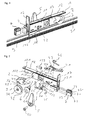
- the selected as an embodiment roller device for insertion into the frame section 81 of a sliding leaf 8 consists essentially of a housing 1 in which a roller holder 2 is pivotally mounted, which receives a roller 3. Furthermore, a locking hook 4 is arranged in the housing 1, which is connected via a rotary cam 51 with an operating lever 5. Adjacent to the operating lever 5, a lock 6 for fixing the locking hook 4 is inserted into the housing 1. On the head side, a hold-down 7 is inserted into the housing 1.
- the housing 1 is made in the embodiment as a metal casting. It is formed from two spaced-apart side walls 11, which are connected to each other via a cover plate 12 and the end via a pivot block 13. In the cover plate 12 threaded holes 121 are introduced for receiving clamping screws 122. Furthermore, in the pivot block 13 at its free end, an eye 131 for pivotally mounting the roller holder 2 is introduced. In addition to the cover plate 12, a threaded through bore 132 for receiving a cylinder screw 133 is additionally introduced into the pivoting block 13. Adjacent to the pivot block 13 are in the side walls 11 mutually aligned recesses 14 for receiving a locking lock 6 and recesses 15 for receiving the rotary cam 51 of the operating lever 5 introduced.
- an axle receptacle 16 for the pivot axis 45 of the locking hook 4 is also arranged in the side walls 11.
- a cap 17 is formed at the top of the housing 1 .
- the cover plate 17 projecting over the cover plate 12 is provided with a recess 171 for the passage of the locking hook 4.
- the recess 171 is bounded on its side opposite the cover plate 12 side by an integrally formed between the side walls 11 web 19, on whose side facing away from the recess 171 an undercut 191 is introduced.
- the cap 17 terminates in arms 18 integrally formed on the side walls 11 at the end. Below the arms 18, these drivers 182 are integrally formed.
- the cap 17 covers the head-side ends of the arms 18 and the driver 182, to which it is integrally formed.
- the roller holder 2 is formed in the manner of a rocker. It has two oppositely arranged legs 21, in which an axle 22 is introduced. On the legs 21, a spring arm 23 is arranged, which projects into the axle 22. At its end facing the pivot block 13, a cylindrical portion 24 is formed on the roller seat 2, which corresponds to the eye 131 of the pivot block 13. Above the cylindrical portion 24, a stop 25 is arranged, the contour of which substantially corresponds to the contour of the stop 134 introduced above the eye 131 against the pivoting block 13. The roller mount 2 is held with its cylindrical portion 24 in the eye 131 of the pivot block 13 pivotally. By guided through the threaded through bore 132 cylinder screw 133, which passes through the pivot block 13 in the region of the stopper 134, a pivoting of the roller receptacle 2 via the contact with the stopper 25 is made possible.
- the roller 3 has an axis 31 on which the roller 3 is rotatably mounted. Outside the roller is provided with a running profile 32 with a U-shaped cross-section.
- the running profile 32 is made in the embodiment of plastic, the roller 3 made of metal.
- the roller 3 is held about its axis 31 in the axle 22 of the roller holder 2.
- the locking hook 4 has a hook portion 41, to which a link portion 42 connects, which opens into a boom 43.
- a bore 44 for receiving a pivot axis 45 is introduced into the locking hook 4.
- the locking hook 4 is pivotally mounted in the housing 1 via the pivot axis 45.
- a slotted guide 421 is introduced for engagement of the rotary cam 51 of the operating lever 5.
- the slide guide 421 is formed such that two locking positions are arranged for the rotary cam 51.
- an opening 431 is introduced in the boom 43.
- the breakthrough 431 is used to reach the above the boom 43 through a threaded hole 121 through the cover plate 12 performed clamping screw 122.
- the locking hook 4 is biased by a leaf spring 46 against the mud cam 51 of the operating lever 5.
- the operating lever 5 is connected via a cylinder screw 50 with a rotary cam 51.
- the rotary cam 51 is provided with a cam part 511 that engages in the slotted guide 421 of the link section 42 of the locking hook 4.
- the cam member 511 opens into a pin 512 which passes through a guide slot 422 introduced in the slide guide 421.
- the pin 512 of the rotary cam 51 bears against one end of the guide slot 422.
- a mushroom-shaped contour element 52 is formed in the rotary cams 51.
- the lock 6 is fixed to the housing 1 via a locking plate 63. It essentially comprises a lock cylinder 61 which is connected to a locking lever 62.
- the lock cylinder 61 is inserted into the recess 14 of the side walls 11, such that the locking lever 62 is aligned vertically in the direction of the cover plate 12.
- the angled arm 43 abuts approximately flush against the free edges of the side walls 11.
- the locking lever 62 can be pivoted by means of a key inserted into the lock cylinder 61 in the direction of the locking hook 4 until it rests on the boom 43.
- the boom 43 is fixed so that pivoting of the locking hook 4 is prevented via the operating lever 5.
- the hold-down 7 is designed substantially cuboid. He has two oppositely molded gripper 71, at the free ends inside parallel webs 72 are integrally formed. Above the gripper 71, a guide groove 73 is introduced into the hold-down 7 at its two longitudinal sides, which are bounded by a stop 731. On its upper side facing away from the grippers 71, a spring arm 74, which has an outwardly directed latching element 741, is integrally formed on the downholder 7. In the exemplary embodiment, the hold-down 7 is designed as a plastic injection molded part.
- the hold-down 7 is inserted between the arms 18 of the housing 1, wherein the guide webs 181 engage in the guide grooves 73 of the blank holder 7 and abut against the stop 731.
- the locking element 741 engages over the spring arm 74 biased against the web 19 in the undercut 191, whereby the hold-7 is fixed in the housing 1.
- the hold-7 is advantageously inserted only after positioning the roller device on the catwalk 91 a bottom rail 9 in the housing 1.
- the hold-down 7 is first pressed onto the catwalk 91 in such a way that the elastic grippers 71 are pressed apart.
- the grippers 71 After overcoming the sliding head 92 of the catwalk 91, the grippers 71 return to their original position, wherein the webs 72 engage behind the sliding head 92 of the catwalk 91. Subsequently, the hold-down along the catwalk 91 on the guide webs 181 of Housing 1 is pushed until the locking element 741 of the spring arm 74 engages in the undercut 191 of the web 19. A lifting of the roller device from the catwalk 91 of the bottom rail 9 is effectively prevented. To remove the roller device from the catwalk 91, the locking lug 741 can be spent by operating the spring arm 74 from the outside from the undercut 191 of the web 19, after which the hold-7 can be pushed out of the housing 1 out.
- a housing 1 is shown in a simplified embodiment. In this case, the entire locking mechanism with locking hook 4, operating lever 5 and lock 6 was recessed.
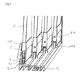
- FIG. 7 For example, a four-lane sliding sash system is shown.
- a roller device is used in the bottom-side frame section 81 of each sliding wing 8.
- the recess provided for this purpose in the frame profile 81 is closed by the cover cap 17 formed on the housing 1.
- the housing 1 is fixed in the frame profile 81 after insertion into the frame profile 81 of a sliding leaf 8 by tightening the clamping screws 122.
- the rollers 3 are placed on the catwalks 91 of the bottom rail 9, wherein the sliding head 92 of the catwalk 91 is encompassed by the running profile 32 of the roller 3.
- the roller devices 1 are secured on hold-downs 7 on the catwalks 91.
- FIG. 7 it can be seen overlap the driver 182 of the housing 1 of the roller device of the sliding sash 8 such that a simultaneous displacement of several sliding sash 8 is possible.
Landscapes
- Engineering & Computer Science (AREA)
- Mechanical Engineering (AREA)
- Support Devices For Sliding Doors (AREA)
- Rehabilitation Tools (AREA)
Description
Die Erfindung betrifft eine Laufrollenvorrichtung zum Einsetzen in das Rahmenprofil eines Schiebeflügels nach dem Oberbegriff des Patentanspruchs 1.The invention relates to a roller device for insertion into the frame profile of a sliding leaf according to the preamble of
Bei der Gestaltung von Schiebeflügelsystemen werden mehrere Schiebeflügel parallel zueinander verschiebbar auf einer Bodenschiene angeordnet. Zur Erzielung einer geöffneten Position einer Schiebewand können dabei die Schiebeelemente hintereinander positioniert werden; zum Verschließen der Wand können sie hintereinander verfahren werden. Hierzu sind die Schiebeflügel bodenseitig mit Laufrollen versehen, mit denen sie auf parallel zueinander angeordnete "Laufstege" der Bodenschienen verfahrbar sind. Deckenseitig sind die Schiebeflügel in einer Deckenschiene geführt. Die Laufrollen sind regelmäßig in einem Rollengehäuse gelagert, welches bodenseitig in das Rahmenprofil des Schiebeflügels eingesetzt ist. Zur Nivellierung des Schiebeflügels ist es bekannt, eine Höhenverstellung der Laufrolle vorzusehen, über welche die Position der Laufrolle relativ zum Laufrollengehäuse verstellbar ist. Hierzu ist es bekannt, die Laufrollen in einer Rollenaufnahme anzuordnen, welche mit einer schiefen Ebene versehen ist, wobei in dem Laufrollengehäuse ein halbzylindrisches Element angeordnet ist, an dem die schiefe Ebene der Rollenauflage anliegt. Durch horizontale Verschiebung der Rollenaufnahme innerhalb des Rollengehäuses gleitet die schiefe Ebene entlang des halbzylindrischen Körpers, wodurch eine Verstellung der Höhe der Laufrolle relativ zum Laufrollengehäuse bewirkt ist.
Die
Nachteilig an dem vorbekannten Laufrollengehäuse ist, dass dieses aufwendig herzustellen ist und zudem einen großen Bauraum beansprucht. Hier will die Erfindung Abhilfe schaffen. Der Erfindung liegt die Aufgabe zur Grunde, eine Laufrollenvorrichtung zum Einsetzen in das Rahmenprofil eines Schiebeflügels zu schaffen, welche einfacher herzustellen ist und die eine kompaktere Bauweise ermöglicht. Gemäß der Erfindung wird diese Aufgabe durch die Merkmale des kennzeichnenden Teils des Patentanspruchs 1 gelöst.In the design of sliding sash systems several sliding panels are arranged parallel to each other displaceable on a bottom rail. To achieve an open position of a sliding wall while the sliding elements can be positioned one behind the other; they can be moved in succession to close the wall. For this purpose, the sliding leaves are provided on the bottom side with rollers with which they are movable on mutually parallel "walkways" of the floor rails. On the ceiling side, the sliding sashes are guided in a ceiling rail. The rollers are regularly stored in a roller housing, which is inserted on the bottom side in the frame profile of the sliding leaf. For leveling the sliding leaf, it is known to provide a height adjustment of the roller over which the position of the roller is adjustable relative to the roller housing. For this purpose, it is known to arrange the rollers in a roller receiving, which is provided with an inclined plane, wherein in the roller housing a semi-cylindrical element is arranged, against which the inclined plane of the roller support. By horizontal displacement of the roller receptacle within the roller housing slides the inclined plane along the semi-cylindrical body, whereby an adjustment of the height of the roller is effected relative to the roller housing.
The
A disadvantage of the previously known roller housing, that this is expensive to manufacture and also claimed a large space. The invention aims to remedy this situation. The invention has for its object to provide a roller device for insertion into the frame profile of a sliding sash, which is easier to manufacture and a more compact Construction allows. According to the invention, this object is solved by the features of the characterizing part of
Mit der Erfindung ist eine Laufrollenvorrichtung zum Einsetzen in das Rahmenprofil eines Schiebeflügels geschaffen, die einfach herzustellen ist und eine kompaktere Bauweise ermöglicht. Durch das Vorsehen einer schwenkbar in dem Gehäuse gelagerten Rollenaufnahme, die über ein innerhalb des Gehäuses bewegbares Einstellelement schwenkbar ist, ist der erforderliche Bewegungsraum zur Höhenverstellung der Laufrolle vermindert.With the invention, a roller device for insertion into the frame profile of a sliding wing is created, which is easy to manufacture and allows a more compact design. By providing a pivotally mounted in the housing roller mount, which is pivotable via a movable within the housing adjustment, the required range of motion for height adjustment of the roller is reduced.
In Weiterbildung der Erfindung ist das Einstellelement durch eine Schraube gebildet, welche gegen die Rollenaufnahme schraubbar ist, wodurch eine Verschwenkung der Rollenaufnahme erzielbar ist. Hierdurch ist eine fein justierbare Höhenverstellung ermöglicht.In a further development of the invention, the adjusting element is formed by a screw which can be screwed against the roller holder, whereby a pivoting of the roller holder can be achieved. As a result, a finely adjustable height adjustment is possible.
In Ausgestaltung der Erfindung ist die schwenkbare Lagerung der Rollenaufnahme durch einen an der Rollenaufnahme angeformten zylindrischen Abschnitt gebildet, der in einem zylindrisch ausgebildeten Auge des Gehäuses angeordnet ist. Hierdurch ist eine einfach realisierbare und zugleich robuste Schwenkachse erzielt. Dabei ist durch die Gestaltung des Übergangs zum zylindrischen Abschnitt im Zusammenspiel mit der Form des Auges einfach eine Begrenzung des Schwenkwinkels der Rollenaufnahme herstellbar.In an embodiment of the invention, the pivotable mounting of the roller receptacle is formed by a molded onto the roller receiving cylindrical portion which is arranged in a cylindrically shaped eye of the housing. As a result, an easily realizable and at the same time robust pivot axis is achieved. In this case, by the design of the transition to the cylindrical portion in conjunction with the shape of the eye simply a limitation of the pivot angle of the roll holder produced.
Gemäß der Erfindung weist die Rollenaufnahme eine Achsaufnahme für eine Rollenachse auf, wobei an der Achsaufnahme ein Federarm angeordnet ist, welcher derart ausgebildet ist, dass er beim Einbringen einer Rollenachse in die Achsaufnahme ausweicht und nach Erreichen der Lagerposition der Rollenachse in seine ursprüngliche Position zurück federt, wodurch die Rollenachse in der Achsaufnahme gehalten ist. Hierdurch ist eine einfache Montage einer Laufrolle durch "einklicken" in die Rollenaufnahme ermöglicht. Durch Zurückhalten des Federarms kann zudem die Laufrolle einfach entnommen werden, wodurch ein verschleißbedingter Wechsel erleichtert ist.According to the invention, the roller receptacle has an axle receptacle for a roller axle, wherein a spring arm is arranged on the axle receptacle, which is designed such that it deflects when introducing a roller axle into the axle receptacle and springs back to its original position after reaching the bearing position of the roller axle , whereby the roller axle is held in the axle receptacle. As a result, a simple installation of a roller by "clicking" in the roller mount allows. By retaining the spring arm also the roller can be easily removed, whereby a wear-related change is facilitated.
In weiterer Ausgestaltung der Erfindung ist an dem Gehäuse eine Abdeckkappe angeformt. Hierdurch ist ein gleichzeitiges Verschließen der Öffnung des Rahmenprofils mit Einbringen des Gehäuses ermöglicht. Ein nachträgliches Verschließen über eine separate Abdeckkappe ist nicht erforderlich.In a further embodiment of the invention, a cap is formed on the housing. This allows a simultaneous closing of the opening of the frame profile with introduction of the housing. A subsequent closing over a separate cap is not required.
In Weiterbildung der Erfindung ist an der Abdeckkappe wenigstens ein seitlich auskragender Mitnehmer angeformt. Durch einen solchen integrierten Mitnehmer ist ein leichtes Verschieben mehrerer Schiebeflügel in einem Schiebeflügelsystem ermöglicht.In a further development of the invention, at least one laterally projecting driver is integrally formed on the cap. By means of such an integrated driver, it is possible to easily move several sliding sashes in a sliding sash system.
In Ausgestaltung der Erfindung ist ein Verriegelungshaken angeordnet, der mit einem Bedienhebel verbunden ist, über den der Verriegelungshaken in eine Verrieglungs- und eine Entrieglungsposition bewegbar ist. Hierdurch ist eine integrierte Verrieglungsmöglichkeit bei einem die Laufrollenvorrichtung aufnehmenden Schiebeflügel bereitgestellt. Eine separate Verrieglungsvorrichtung ist nicht erforderlich.In an embodiment of the invention, a locking hook is arranged, which is connected to an operating lever, via which the locking hook is movable in a Verrieglungs- and an Entrieglungsposition. As a result, an integrated Verrieglungsmöglichkeit is provided at a the roller device receiving sliding sash. A separate locking device is not required.
Vorteilhaft ist ein Sperrschloss zur Festlegung des Verriegelungshakens in der Verrieglungsposition angeordnet. Hierdurch ist die Verhinderung eines unbefugten Verschiebens eines Schiebeflügels ermöglicht.Advantageously, a locking lock for fixing the locking hook is arranged in the Verrieglungsposition. This makes it possible to prevent unauthorized shifting of a sliding sash.
In weiterer Ausgestaltung der Erfindung weist der Verriegelungshaken einen Ausleger auf, an den ein Sperrhebel des Sperrschlosses in Verriegelungsposition des Verrieglungshakens anlegbar ist, wodurch eine Festlegung des Verrieglungshakens bewirkt ist. Hierdurch ist eine gehäuseintegrierte, autarke abschließbare Festlegung des Verriegelungshakens erzielt. Eine Interaktion beispielsweise mit einem Laufsteg der Bodenschiene findet nicht statt.In a further embodiment of the invention, the locking hook on a boom to which a locking lever of the locking lock in the locking position of Verrieglungshakens can be applied, whereby a determination of the Verrieglungshakens is effected. As a result, a housing integrated, self-contained lockable determination of the locking hook is achieved. An interaction, for example, with a catwalk of the floor rail does not take place.
In Weiterbildung der Erfindung ist der Verriegelungshaken mit einer Kulissenführung versehen, in die ein mit dem Bedienhebel verbundener Drehnocken eingreift, wobei der Verriegelungshaken über eine Feder gegen den Drehnocken vorgespannt ist, derart, dass der Bedienhebel in zwei definierte Drehpositionen arretierbar ist. Hierdurch sind zwei definierte Stellungen Entriegelungsposition/Verriegelungsposition ermöglicht, wodurch beispielsweise einem unbeab-sichtigtem Verriegeln eines Schiebeflügels entgegen gewirkt ist.In a further development of the invention, the locking hook is provided with a slotted guide, in which engages a connected to the operating lever rotary cam, wherein the locking hook is biased by a spring against the rotary cam, such that the operating lever can be locked in two defined rotational positions is. As a result, two defined positions unlocking / locking position allows, which is counteracted, for example, an unintentional locking a sliding sash.
In weiterer Ausgestaltung der Erfindung ist ein Einschub zur lösbaren Aufnahme eines Niederhalters angeordnet. Hierdurch ist eine temporäre Entnahme des Niederhalters für Montage- bzw. Demontagezwecke ermöglicht.In a further embodiment of the invention, a drawer for releasably receiving a hold-down is arranged. This allows a temporary removal of the blank holder for assembly or disassembly purposes.
In Weiterbildung der Erfindung ist der Einschub durch zwei parallel angeordnete Arme gebildet, an denen an ihrer dem jeweils gegenüberliegenden Arm zugewandten Seite ein Führungssteg angeformt ist, welche Führungsstege in an zwei gegenüberliegenden Seiten des Niederhalters angeordnete Führungsnuten eingreifen. Hierdurch ist die einfache Herstellung eines bodenschienennahen Einschubes ermöglicht.In a further development of the invention, the insert is formed by two arms arranged in parallel, on which on its side facing the respective opposite arm a guide web is integrally formed, which guide webs engage in arranged on two opposite sides of the hold-down guide grooves. As a result, the simple production of a slot close to the slot is possible.
Bevorzugt ist oberhalb des Niederhalters zwischen den Armen in dem Gehäuse ein Hinterschnitt angeordnet, der von einem an dem Niederhalter angeordneten Rastelement hintergriffen ist. Hierdurch ist eine einfache Fixierung des Niederhalters in dem Einschub ermöglicht.Preferably, an undercut is disposed above the hold-down between the arms in the housing, which is engaged behind by a latching element arranged on the hold-down. As a result, a simple fixation of the blank holder is made possible in the slot.
In weiterer Ausgestaltung der Erfindung weist der Niederhalter an seiner dem Hinterschnitt abgewandten Seite zwei gegenüberliegend angeordnete Greifer zum Umschließen des Gleitkopfes eines Laufsteges auf. Hierdurch ist ein einfaches Aufbringen des Niederhalters auf einen Laufsteg vor dem Einbringen in den Einschub des Gehäuses ermöglicht.In a further embodiment of the invention, the hold-down on its side facing away from the undercut two oppositely arranged gripper for enclosing the sliding head of a catwalk on. As a result, a simple application of the blank holder is made possible on a catwalk before insertion into the slot of the housing.
Andere Weiterbildungen und Ausgestaltungen der Erfindung sind in den übrigen Ansprüchen angegeben. Ein Ausführungsbeispiel der Erfindung ist in den Zeichnungen dargestellt und wird nachfolgend im Einzelnen beschrieben. Es zeigen:
Figur 1- die schematische Darstellung einer auf einer Bodenschiene angeordneten Laufrollenvorrichtung;
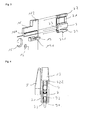
Figur 2- die Laufrollenvorrichtung aus
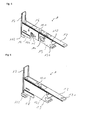
Figur 1 Figur 3- die Detailansicht des Niederhaltereinschubs der Laufrollenvorrichtung aus
Figur 1 Figur 4- die Darstellung der Laufrollenvorrichtung aus
Figur 1 Figur 5- die räumliche Darstellung des Gehäuses der Laufrollenvorrichtung aus
Figur 1 Figur 6- die Darstellung eines Gehäuses in einer weiteren Ausführungsform und
Figur 7- die schematische Darstellung eines vierspurigen Schiebeflügelsystems.
- FIG. 1
- the schematic representation of a arranged on a bottom rail roller device;
- FIG. 2
- the caster device
FIG. 1 in exploded view; - FIG. 3
- the detailed view of the hold-down insert of the roller device
FIG. 1 in sectional view; - FIG. 4
- the representation of the roller device
FIG. 1 in the view from the front; - FIG. 5
- the spatial representation of the housing of the roller device
FIG. 1 ; - FIG. 6
- the representation of a housing in a further embodiment and
- FIG. 7
- the schematic representation of a four-lane sliding wing system.
Die als Ausführungsbeispiel gewählte Laufrollenvorrichtung zum Einsetzen in das Rahmenprofil 81 eines Schiebeflügels 8 besteht im Wesentlichen aus einem Gehäuse 1, in dem eine Rollenaufnahme 2 schwenkbar gelagert ist, welche eine Laufrolle 3 aufnimmt. Weiterhin ist in dem Gehäuse 1 ein Verriegelungshaken 4 angeordnet, der über eine Drehnocke 51 mit einem Bedienhebel 5 verbunden ist. Benachbart zu dem Bedienhebel 5 ist in das Gehäuse 1 ein Sperrschloss 6 zur Festlegung des Verriegelungshakens 4 eingebracht. Kopfseitig ist in das Gehäuse 1 ein Niederhalter 7 eingeschoben.The selected as an embodiment roller device for insertion into the
Das Gehäuse 1 ist im Ausführungsbeispiel als Metallgussteil hergestellt. Es ist gebildet aus zwei beabstandet angeordneten Seitenwänden 11, die über ein Deckblech 12 sowie endseitig über einen Schwenkblock 13 miteinander verbunden sind. In dem Deckblech 12 sind Gewindebohrungen 121 zur Aufnahme von Spannschrauben 122 eingebracht. Weiterhin ist in den Schwenkblock 13 an seinem freien Ende ein Auge 131 zur schwenkbaren Lagerung der Rollenaufnahme 2 eingebracht. Parallel zum Deckblech 12 ist in den Schwenkblock 13 darüber hinaus eine Gewindedurchgangsbohrung 132 zur Aufnahme einer Zylinderschraube 133 eingebracht. Benachbart zum Schwenkblock 13 sind in die Seitenwände 11 zueinander fluchtend jeweils Ausnehmungen 14 zur Aufnahme eines Sperrschlosses 6 sowie Ausnehmungen 15 zur Aufnahme der Drehnocke 51 des Bedienhebels 5 eingebracht. Schräg versetzt zur Ausnehmung 15 ist in die Seitenwände 11 weiterhin eine Achsaufnahme 16 für die Schwenkachse 45 des Verrieglungshakens 4 angeordnet. Kopfseitig ist an das Gehäuse 1 eine Abdeckkappe 17 angeformt. Die das Deckblech 12 überragende Abdeckkappe 17 ist zum Durchtritt des Verrieglungshakens 4 mit einer Ausnehmung 171 versehen. Die Ausnehmung 171 wird an ihrer dem Deckblech 12 entgegen gesetzten Seite durch einen zwischen den Seitenwänden 11 angeformten Steg 19 begrenzt, an dessen der Ausnehmung 171 abgewandten Seite ein Hinterschnitt 191 eingebracht ist. Die Abdeckkappe 17 mündet in endseitig an die Seitenwände 11 angeformten Arme 18. Unterhalb der Arme 18 sind an diese Mitnehmer 182 angeformt. Die Abdeckkappe 17 überdeckt die kopfseitigen Enden der Arme 18 sowie der Mitnehmer 182, an die sie angeformt ist.The
Die Rollenaufnahme 2 ist in Art eine Schwinge ausgebildet. Sie weist zwei gegenüberliegend angeordnete Schenkel 21 auf, in die eine Achsaufnahme 22 eingebracht ist. An die Schenkel 21 ist ein Federarm 23 angeordnet, der in die Achsaufnahme 22 hineinragt. An ihrem den Schwenkblock 13 zugewandten Ende ist an der Rollenaufnahme 2 ein zylindrischer Abschnitt 24 angeformt, der mit dem Auge 131 des Schwenkblocks 13 korrespondiert. Oberhalb des zylindrischen Abschnitts 24 ist ein Anschlag 25 angeordnet, dessen Kontur im Wesentlichen der Kontur des oberhalb des Auges 131 an den Schwenkblock 13 eingebrachten Anschlags 134 entspricht. Die Rollenaufnahme 2 ist mit ihrem zylindrischen Abschnitt 24 in dem Auge 131 des Schwenkblocks 13 schwenkbar gehalten. Durch die durch die Gewindedurchgangsbohrung 132 geführte Zylinderschraube 133, welche durch den Schwenkblock 13 im Bereich des Anschlags 134 durchtritt, ist ein Verschwenken der Rollenaufnahme 2 über den Kontakt mit dem Anschlag 25 ermöglicht.The
Die Laufrolle 3 weist eine Achse 31 auf, auf der die Laufrolle 3 drehbar gelagert ist. Außen ist die Laufrolle mit einem Laufprofil 32 mit U-förmigen Querschnitt versehen. Das Laufprofil 32 ist im Ausführungsbeispiel aus Kunststoff, die Laufrolle 3 aus Metall hergestellt. Die Laufrolle 3 ist über ihre Achse 31 in der Achsaufnahme 22 der Rollenaufnahme 2 gehalten.The
Der Verriegelungshaken 4 weist einen Hakenabschnitt 41 auf, an den sich ein Kulissenabschnitt 42 anschließt, der in einen Ausleger 43 mündet. Im Übergang von Hakenabschnitt 41 und Kulissenabschnitt 42 ist in den Verriegelungshaken 4 eine Bohrung 44 zur Aufnahme einer Schwenkachse 45 eingebracht. Der Verriegelungshaken 4 ist über die Schwenkachse 45 in dem Gehäuse 1 schwenkbar gelagert. In dem Kulissenabschnitt 42 ist eine Kulissenführung 421 zum Eingriff des Drehnockens 51 des Bedienhebels 5 eingebracht. Dabei ist die Kulissenführung 421 derart ausgebildet, dass zwei Arretierungspositionen für den Drehnocken 51 angeordnet sind. In den Ausleger 43 ist ein Durchbruch 431 eingebracht. Der Durchbruch 431 dient der Erreichbarkeit des oberhalb des Auslegers 43 durch eine Gewindebohrung 121 durch das Deckblech 12 durchgeführten Spannschraube 122. Der Verriegelungshaken 4 ist über eine Blattfeder 46 gegen den Drecknocken 51 des Bedienhebels 5 vorgespannt.The
Der Bedienhebel 5 ist über eine Zylinderschraube 50 mit einem Drehnocken 51 verbunden. Der Drehnocken 51 ist mit einem Nockenteil 511 versehen, dass in die Kulissenführung 421 des Kulissenabschnitts 42 des Verriegelungshakens 4 eingreift. Dabei mündet das Nockenteil 511 in einen Stift 512, der durch einen in der Kulissenführung 421 eingebrachten Führungsschlitz 422 durchtritt. In den beiden Arretierstellungen liegt der Stift 512 des Drehnockens 51 an jeweils einem Ende des Führungsschlitzes 422 an. Auf seiner dem Bedienhebel 5 gegenüberliegenden Seite ist in den Drehnocken 51 ein pilzförmig ausgebildetes Konturelement 52 angeformt. Durch Einbringen eines Schlitzwerkzeuges in das Konturelement 52 ist eine Betätigung des Drehnockens 51 auf der dem Bedienhebel 5 abgewandten Seite des Gehäuses 1 ermöglicht. Anstelle eines schlitzförmigen Konturelementes 52 kann selbstverständlich auch ein als Innenmehrkant ausgeformtes oder mit einer sonstigen Kontur versehenes Konturelement 52 angeordnet sein, welches über ein korrespondierendes Werkzeug betätigbar ist.The operating
Das Sperrschloss 6 ist über ein Sicherungsblech 63 an dem Gehäuse 1 fixiert. Es umfasst im Wesentlichen einen Schließzylinder 61, der mit einem Sperrhebel 62 verbunden ist. Der Schließzylinder 61 ist in die Ausnehmung 14 der Seitenwände 11 eingebracht, derart, dass der Sperrhebel 62 vertikal in Richtung des Deckblechs 12 ausgerichtet ist. In Schließposition des Verriegelungshakens 4 liegt der abgewinkelte Ausleger 43 etwa bündig an den freien Kanten der Seitenwände 11 an. In dieser Stellung kann der Sperrhebel 62 mittels eines in den Schließzylinder 61 eingeführten Schlüssels in Richtung des Verriegelungshakens 4 verschwenkt werden, bis er auf dem Ausleger 43 aufliegt. In dieser Stellung ist der Ausleger 43 festgelegt, sodass ein Verschwenken des Verriegelungshakens 4 über den Bedienhebel 5 verhindert ist.The
Der Niederhalter 7 ist im Wesentlichen quaderförmig ausgeführt. Er weist zwei gegenüberliegend angeformte Greifer 71 auf, an deren freien Enden innen parallel zueinander Stege 72 angeformt sind. Oberhalb der Greifer 71 ist in den Niederhalter 7 an seinen beiden Längsseiten jeweils eine Führungsnut 73 eingebracht, die durch einen Anschlag 731 begrenzt sind. An seiner den Greifern 71 abgewandten Oberseite ist an dem Niederhalter 7 ein Federarm 74 angeformt, der ein nach außen gerichtetes Rastelement 741 aufweist. Im Ausführungsbeispiel ist der Niederhalter 7 als Kunststoffspritzgussteil ausgeführt.The hold-
Der Niederhalter 7 ist zwischen die Arme 18 des Gehäuses 1 eingeschoben, wobei die Führungsstege 181 in die Führungsnuten 73 des Niederhalters 7 eingreifen und an dem Anschlag 731 anliegen. Dabei greift das Rastelement 741 über den Federarm 74 gegen den Steg 19 vorgespannt in den Hinterschnitt 191 ein, wodurch der Niederhalter 7 in dem Gehäuse 1 fixiert ist. Der Niederhalter 7 wird vorteilhaft erst nach Positionierung der Laufrollenvorrichtung auf dem Laufsteg 91 einer Bodenschiene 9 in das Gehäuse 1 eingefügt. Dabei wird der Niederhalter 7 zunächst derart auf den Laufsteg 91 aufgedrückt, dass die elastischen Greifer 71 auseinander gepresst werden. Nach Überwindung des Gleitkopfes 92 des Laufsteges 91 nehmen die Greifer 71 wieder ihre ursprüngliche Position ein, wobei die Stege 72 den Gleitkopf 92 des Laufstegs 91 hintergreifen. Anschließend wird der Niederhalter entlang des Laufstegs 91 auf die Führungsstege 181 des Gehäuses 1 aufgeschoben, bis das Rastelement 741 des Federarms 74 in den Hinterschnitt 191 des Steges 19 eingreift. Ein Ausheben der Laufrollenvorrichtung vom Laufsteg 91 der Bodenschiene 9 ist so wirksam verhindert. Zum Abnehmen der Laufrollenvorrichtung von dem Laufsteg 91 kann die Rastnase 741 durch Betätigung des Federarms 74 von außen aus dem Hinterschnitt 191 des Steges 19 verbracht werden, wonach der Niederhalter 7 aus dem Gehäuse 1 heraus geschoben werden kann. In
In
Claims (13)
- Track roller device for inserting into the frame profile of a sliding partition section, with a housing which holds at least one track roller, with means of adjusting the height of the track roller, where the means of adjusting the height of the track roller (3) comprise a roller retainer (2) mounted to pivot in the housing (1), which roller retainer (2) can be pivoted via a movable adjusting element within the housing (1), where the roller retainer (2) has an axle seat (22) for a roller axle (31) which is mounted in two legs (21) of the roller retainer arranged opposite one another, characterised in that a spring arm (23) is also mounted on the axle seat (22) in such a way that it projects into the axle seat (22), and which is formed in such a way that it deflects when the roller axle (31) is inserted into the axle seat (22), and then springs back to its original position when the roller axle (31) has reached its final mounting position, thereby holding the roller axle (31) in the axle seat (22).
- Track roller device in accordance with claim 1, characterised in that the adjusting element is formed by a screw (133) which can be screwed against the roller retainer (2) thereby enabling the roller retainer (2) to be pivoted.
- Track roller device in accordance with claim 1 or claim 2, characterised in that the pivoting mounting of the roller retainer (2) is formed by a cylindrical section (24) formed on the roller retainer (2) and which is arranged in a cylindrically shaped eye (131) of the housing (1).
- Track roller device in accordance with any of the aforementioned claims, characterised in that a covering cap (17) is formed on the housing (1).
- Track roller device in accordance with claim 4, characterised in that at least one laterally protruding catch (182) is formed on the covering cap (17).
- Track roller device in accordance with any of the aforementioned claims, characterised in that a locking hook (4) is provided which is connected to an operating lever (5) by means of which the locking hook (4) can be moved into a locked and an unlocked position.
- Track roller device in accordance with claim 6, characterised in that a lock (6) is provided for fixing the locking hook (4) in the locked position.
- Track roller device in accordance with claim 7, characterised in that the locking hook (4) has an extension (43) against which a catch lever (62) of the lock (6) is laid in the locked position of the locking hook (4), thereby fixing the locking hook (4) in position.
- Track roller device in accordance with any of the claims 6 to 8, characterised in that the locking hook (4) is fitted with a sliding block guide (421) into which a rotating tappet (51) connected to the operating lever (5) hooks, where the locking hook (4) is pressed against the rotating tappet (51) by a spring (46) in such a way that the operating lever (5) can be locked in two defined rotation positions.
- Track roller device in accordance with any of the aforementioned claims, characterised in that a slide-in element is provided for the detachable engagement of a retaining block (7).
- Track roller device in accordance with claim 10, characterised in that the slide-in element is formed by two parallel arms (18) on each of which arms a guide ridge (181) is formed on the side facing the opposite arm, which guide ridges (181) engage the guide grooves (73) arranged on the two opposite sides of the retaining block (7).
- Track roller device in accordance with claim 11, characterised in that an undercut (191) is arranged above the retaining block (7) between the arms (18) in the housing, into which undercut a catch (741) arranged on the retaining block (7) hooks.
- Track roller device in accordance with claim 12, characterised in that the retaining block (7) has two grippers (71) arranged opposite one another on the side facing away from the undercut (191) for embracing the sliding head (92) of a catwalk (91).
Priority Applications (4)
| Application Number | Priority Date | Filing Date | Title |
|---|---|---|---|
| EP11000235.9A EP2476840B1 (en) | 2011-01-13 | 2011-01-13 | Track roller device |
| ES11000235.9T ES2534194T3 (en) | 2011-01-13 | 2011-01-13 | Roller Roller Device |
| PT11000235T PT2476840E (en) | 2011-01-13 | 2011-01-13 | ROLLER DEVICE |
| PL11000235T PL2476840T3 (en) | 2011-01-13 | 2011-01-13 | Track roller device |
Applications Claiming Priority (1)
| Application Number | Priority Date | Filing Date | Title |
|---|---|---|---|
| EP11000235.9A EP2476840B1 (en) | 2011-01-13 | 2011-01-13 | Track roller device |
Publications (2)
| Publication Number | Publication Date |
|---|---|
| EP2476840A1 EP2476840A1 (en) | 2012-07-18 |
| EP2476840B1 true EP2476840B1 (en) | 2015-01-07 |
Family
ID=44145118
Family Applications (1)
| Application Number | Title | Priority Date | Filing Date |
|---|---|---|---|
| EP11000235.9A Active EP2476840B1 (en) | 2011-01-13 | 2011-01-13 | Track roller device |
Country Status (4)
| Country | Link |
|---|---|
| EP (1) | EP2476840B1 (en) |
| ES (1) | ES2534194T3 (en) |
| PL (1) | PL2476840T3 (en) |
| PT (1) | PT2476840E (en) |
Cited By (1)
| Publication number | Priority date | Publication date | Assignee | Title |
|---|---|---|---|---|
| EP4223971A3 (en) * | 2018-01-15 | 2023-08-16 | Gebr. Willach GmbH | Telescopic sliding door system |
Families Citing this family (9)
| Publication number | Priority date | Publication date | Assignee | Title |
|---|---|---|---|---|
| FI20135394L (en) * | 2013-04-19 | 2014-10-20 | Alutec Oy | Window system |
| DE102013111467A1 (en) * | 2013-10-17 | 2015-04-23 | Dorma Deutschland Gmbh | Multi Castle |
| NL2014332B1 (en) * | 2015-02-20 | 2016-10-13 | Lss Lewens Sonnenschutz-Systeme Gmbh & Co Kg | Sliding door. |
| DE102015003425A1 (en) * | 2015-03-17 | 2016-09-22 | Günther Zimmer | Sliding door with door furniture independent door fitting |
| FI128008B (en) | 2015-04-09 | 2019-07-31 | Alutec Oy | window systems |
| DE202016000481U1 (en) * | 2016-01-27 | 2016-02-11 | Erhardt Markisenbau Gmbh | Device for closing building openings |
| ES2644164A1 (en) * | 2016-05-31 | 2017-11-27 | Bsh Electrodomésticos España, S.A. | GAS COOKING HOB |
| IT201900020590A1 (en) * | 2019-11-08 | 2021-05-08 | Pratic F Lli Orioli S P A | TROLLEY FOR SLIDING DOOR |
| IT201900020904A1 (en) | 2019-11-12 | 2021-05-12 | Metalglas Bonomi S R L | MOVABLE PANEL SYSTEM WITH TROLLEY DEVICE |
Citations (1)
| Publication number | Priority date | Publication date | Assignee | Title |
|---|---|---|---|---|
| GB1594822A (en) * | 1978-05-08 | 1981-08-05 | Widney Windows Ltd H S C | Catch devices for sliding panels |
Family Cites Families (6)
| Publication number | Priority date | Publication date | Assignee | Title |
|---|---|---|---|---|
| US3395490A (en) * | 1966-05-09 | 1968-08-06 | Arthur G. Diack | Sliding-door latching and locking device |
| US3526995A (en) * | 1969-02-03 | 1970-09-08 | Robert M Saunders | Roller assembly for sliding doors |
| NL7807444A (en) * | 1977-07-15 | 1979-01-17 | Hunter Douglas Ind Bv | MULTIPLE PANEL SLIDING DOORS. |
| US4639970A (en) * | 1984-11-29 | 1987-02-03 | Alcan Aluminum Corporation | Roller assembly with stabilizer elements for sliding panels |
| FR2579262A1 (en) * | 1985-03-21 | 1986-09-26 | Krieg & Zivy | ANTI-HANGING DEVICE FOR SLIDING DOOR |
| ATE373762T1 (en) * | 2003-07-03 | 2007-10-15 | Home Decor Holding Company | SLIDING DOOR |
-
2011
- 2011-01-13 EP EP11000235.9A patent/EP2476840B1/en active Active
- 2011-01-13 PT PT11000235T patent/PT2476840E/en unknown
- 2011-01-13 ES ES11000235.9T patent/ES2534194T3/en active Active
- 2011-01-13 PL PL11000235T patent/PL2476840T3/en unknown
Patent Citations (1)
| Publication number | Priority date | Publication date | Assignee | Title |
|---|---|---|---|---|
| GB1594822A (en) * | 1978-05-08 | 1981-08-05 | Widney Windows Ltd H S C | Catch devices for sliding panels |
Cited By (1)
| Publication number | Priority date | Publication date | Assignee | Title |
|---|---|---|---|---|
| EP4223971A3 (en) * | 2018-01-15 | 2023-08-16 | Gebr. Willach GmbH | Telescopic sliding door system |
Also Published As
| Publication number | Publication date |
|---|---|
| PL2476840T3 (en) | 2015-07-31 |
| ES2534194T3 (en) | 2015-04-20 |
| PT2476840E (en) | 2015-03-30 |
| EP2476840A1 (en) | 2012-07-18 |
Similar Documents
| Publication | Publication Date | Title |
|---|---|---|
| EP2476840B1 (en) | Track roller device | |
| DE2913186C2 (en) | Tiltable roller bearing | |
| EP2476828B1 (en) | Locking device | |
| DE102010038141A1 (en) | Fitting for a sliding door | |
| EP3045638B1 (en) | Sliding and rotating leaf system | |
| EP1403142A1 (en) | Vehicle roof rack | |
| DE102007014420B4 (en) | Device for fixing objects | |
| EP3159466B1 (en) | Locking device comprising two movable locking bodies | |
| EP2476841B1 (en) | Device for securing a sliding wing of a sliding wing system | |
| DE102012104813A1 (en) | Guide arrangement of a sliding door of a sliding door furniture | |
| EP2735675B1 (en) | Closure device for doors with an asymmetric escutcheon | |
| DE202009011042U1 (en) | sliding door hardware | |
| EP1700554B1 (en) | Partition wall | |
| EP3835526B1 (en) | Sliding and rotating leaf system | |
| EP3183408B1 (en) | Control element for a fitting arrangement | |
| DE202012012523U1 (en) | lock assembly | |
| EP3168394B1 (en) | Block for a door opener or a strike plate | |
| DE69010903T2 (en) | LOCKING DEVICE FOR A DOOR. | |
| DE102011003371A1 (en) | Locking arrangement for windows, doors or the like with a pivot bolt | |
| EP1662627A1 (en) | Device for detachably fixing an apparatus housing to a mounting rail | |
| DE20211508U1 (en) | Double cylinder pivoting lever closure | |
| EP2602413B1 (en) | Locking equipment for locking a window or door shutter | |
| DE102005020194B4 (en) | Arrangement of a bolt lock with a closure counterpart on a furniture door | |
| EP2168809A1 (en) | Holding device for securing packing rods | |
| DE102005003394B4 (en) | Guide system, in particular for shower and bathtub partitions |
Legal Events
| Date | Code | Title | Description |
|---|---|---|---|
| PUAI | Public reference made under article 153(3) epc to a published international application that has entered the european phase |
Free format text: ORIGINAL CODE: 0009012 |
|
| 17P | Request for examination filed |
Effective date: 20120522 |
|
| AK | Designated contracting states |
Kind code of ref document: A1 Designated state(s): AL AT BE BG CH CY CZ DE DK EE ES FI FR GB GR HR HU IE IS IT LI LT LU LV MC MK MT NL NO PL PT RO RS SE SI SK SM TR |
|
| AX | Request for extension of the european patent |
Extension state: BA ME |
|
| 17Q | First examination report despatched |
Effective date: 20121008 |
|
| GRAP | Despatch of communication of intention to grant a patent |
Free format text: ORIGINAL CODE: EPIDOSNIGR1 |
|
| INTG | Intention to grant announced |
Effective date: 20141015 |
|
| GRAS | Grant fee paid |
Free format text: ORIGINAL CODE: EPIDOSNIGR3 |
|
| GRAA | (expected) grant |
Free format text: ORIGINAL CODE: 0009210 |
|
| AK | Designated contracting states |
Kind code of ref document: B1 Designated state(s): AL AT BE BG CH CY CZ DE DK EE ES FI FR GB GR HR HU IE IS IT LI LT LU LV MC MK MT NL NO PL PT RO RS SE SI SK SM TR |
|
| AX | Request for extension of the european patent |
Extension state: BA ME |
|
| REG | Reference to a national code |
Ref country code: GB Ref legal event code: FG4D Free format text: NOT ENGLISH |
|
| REG | Reference to a national code |
Ref country code: CH Ref legal event code: EP |
|
| REG | Reference to a national code |
Ref country code: IE Ref legal event code: FG4D Free format text: LANGUAGE OF EP DOCUMENT: GERMAN |
|
| REG | Reference to a national code |
Ref country code: AT Ref legal event code: REF Ref document number: 705875 Country of ref document: AT Kind code of ref document: T Effective date: 20150215 |
|
| REG | Reference to a national code |
Ref country code: DE Ref legal event code: R096 Ref document number: 502011005513 Country of ref document: DE Effective date: 20150219 |
|
| REG | Reference to a national code |
Ref country code: CH Ref legal event code: NV Representative=s name: DR.-ING. ULRICH KOETTER, CH |
|
| REG | Reference to a national code |
Ref country code: NL Ref legal event code: T3 |
|
| REG | Reference to a national code |
Ref country code: PT Ref legal event code: SC4A Free format text: AVAILABILITY OF NATIONAL TRANSLATION Effective date: 20150316 |
|
| REG | Reference to a national code |
Ref country code: ES Ref legal event code: FG2A Ref document number: 2534194 Country of ref document: ES Kind code of ref document: T3 Effective date: 20150420 |
|
| REG | Reference to a national code |
Ref country code: LT Ref legal event code: MG4D |
|
| PG25 | Lapsed in a contracting state [announced via postgrant information from national office to epo] |
Ref country code: HR Free format text: LAPSE BECAUSE OF FAILURE TO SUBMIT A TRANSLATION OF THE DESCRIPTION OR TO PAY THE FEE WITHIN THE PRESCRIBED TIME-LIMIT Effective date: 20150107 Ref country code: BG Free format text: LAPSE BECAUSE OF FAILURE TO SUBMIT A TRANSLATION OF THE DESCRIPTION OR TO PAY THE FEE WITHIN THE PRESCRIBED TIME-LIMIT Effective date: 20150407 Ref country code: SE Free format text: LAPSE BECAUSE OF FAILURE TO SUBMIT A TRANSLATION OF THE DESCRIPTION OR TO PAY THE FEE WITHIN THE PRESCRIBED TIME-LIMIT Effective date: 20150107 Ref country code: NO Free format text: LAPSE BECAUSE OF FAILURE TO SUBMIT A TRANSLATION OF THE DESCRIPTION OR TO PAY THE FEE WITHIN THE PRESCRIBED TIME-LIMIT Effective date: 20150407 Ref country code: LT Free format text: LAPSE BECAUSE OF FAILURE TO SUBMIT A TRANSLATION OF THE DESCRIPTION OR TO PAY THE FEE WITHIN THE PRESCRIBED TIME-LIMIT Effective date: 20150107 |
|
| REG | Reference to a national code |
Ref country code: PL Ref legal event code: T3 |
|
| PG25 | Lapsed in a contracting state [announced via postgrant information from national office to epo] |
Ref country code: GR Free format text: LAPSE BECAUSE OF FAILURE TO SUBMIT A TRANSLATION OF THE DESCRIPTION OR TO PAY THE FEE WITHIN THE PRESCRIBED TIME-LIMIT Effective date: 20150408 Ref country code: RS Free format text: LAPSE BECAUSE OF FAILURE TO SUBMIT A TRANSLATION OF THE DESCRIPTION OR TO PAY THE FEE WITHIN THE PRESCRIBED TIME-LIMIT Effective date: 20150107 Ref country code: LV Free format text: LAPSE BECAUSE OF FAILURE TO SUBMIT A TRANSLATION OF THE DESCRIPTION OR TO PAY THE FEE WITHIN THE PRESCRIBED TIME-LIMIT Effective date: 20150107 Ref country code: IS Free format text: LAPSE BECAUSE OF FAILURE TO SUBMIT A TRANSLATION OF THE DESCRIPTION OR TO PAY THE FEE WITHIN THE PRESCRIBED TIME-LIMIT Effective date: 20150507 |
|
| REG | Reference to a national code |
Ref country code: DE Ref legal event code: R097 Ref document number: 502011005513 Country of ref document: DE |
|
| PG25 | Lapsed in a contracting state [announced via postgrant information from national office to epo] |
Ref country code: EE Free format text: LAPSE BECAUSE OF FAILURE TO SUBMIT A TRANSLATION OF THE DESCRIPTION OR TO PAY THE FEE WITHIN THE PRESCRIBED TIME-LIMIT Effective date: 20150107 Ref country code: RO Free format text: LAPSE BECAUSE OF FAILURE TO SUBMIT A TRANSLATION OF THE DESCRIPTION OR TO PAY THE FEE WITHIN THE PRESCRIBED TIME-LIMIT Effective date: 20150107 Ref country code: DK Free format text: LAPSE BECAUSE OF FAILURE TO SUBMIT A TRANSLATION OF THE DESCRIPTION OR TO PAY THE FEE WITHIN THE PRESCRIBED TIME-LIMIT Effective date: 20150107 Ref country code: SK Free format text: LAPSE BECAUSE OF FAILURE TO SUBMIT A TRANSLATION OF THE DESCRIPTION OR TO PAY THE FEE WITHIN THE PRESCRIBED TIME-LIMIT Effective date: 20150107 Ref country code: CZ Free format text: LAPSE BECAUSE OF FAILURE TO SUBMIT A TRANSLATION OF THE DESCRIPTION OR TO PAY THE FEE WITHIN THE PRESCRIBED TIME-LIMIT Effective date: 20150107 Ref country code: MC Free format text: LAPSE BECAUSE OF FAILURE TO SUBMIT A TRANSLATION OF THE DESCRIPTION OR TO PAY THE FEE WITHIN THE PRESCRIBED TIME-LIMIT Effective date: 20150107 |
|
| REG | Reference to a national code |
Ref country code: IE Ref legal event code: MM4A |
|
| PLBE | No opposition filed within time limit |
Free format text: ORIGINAL CODE: 0009261 |
|
| STAA | Information on the status of an ep patent application or granted ep patent |
Free format text: STATUS: NO OPPOSITION FILED WITHIN TIME LIMIT |
|
| 26N | No opposition filed |
Effective date: 20151008 |
|
| REG | Reference to a national code |
Ref country code: FR Ref legal event code: PLFP Year of fee payment: 6 |
|
| PG25 | Lapsed in a contracting state [announced via postgrant information from national office to epo] |
Ref country code: IE Free format text: LAPSE BECAUSE OF NON-PAYMENT OF DUE FEES Effective date: 20150113 |
|
| PG25 | Lapsed in a contracting state [announced via postgrant information from national office to epo] |
Ref country code: SI Free format text: LAPSE BECAUSE OF FAILURE TO SUBMIT A TRANSLATION OF THE DESCRIPTION OR TO PAY THE FEE WITHIN THE PRESCRIBED TIME-LIMIT Effective date: 20150107 |
|
| PG25 | Lapsed in a contracting state [announced via postgrant information from national office to epo] |
Ref country code: MT Free format text: LAPSE BECAUSE OF FAILURE TO SUBMIT A TRANSLATION OF THE DESCRIPTION OR TO PAY THE FEE WITHIN THE PRESCRIBED TIME-LIMIT Effective date: 20150107 |
|
| REG | Reference to a national code |
Ref country code: FR Ref legal event code: PLFP Year of fee payment: 7 |
|
| PG25 | Lapsed in a contracting state [announced via postgrant information from national office to epo] |
Ref country code: HU Free format text: LAPSE BECAUSE OF FAILURE TO SUBMIT A TRANSLATION OF THE DESCRIPTION OR TO PAY THE FEE WITHIN THE PRESCRIBED TIME-LIMIT; INVALID AB INITIO Effective date: 20110113 Ref country code: SM Free format text: LAPSE BECAUSE OF FAILURE TO SUBMIT A TRANSLATION OF THE DESCRIPTION OR TO PAY THE FEE WITHIN THE PRESCRIBED TIME-LIMIT Effective date: 20150107 |
|
| PG25 | Lapsed in a contracting state [announced via postgrant information from national office to epo] |
Ref country code: CY Free format text: LAPSE BECAUSE OF FAILURE TO SUBMIT A TRANSLATION OF THE DESCRIPTION OR TO PAY THE FEE WITHIN THE PRESCRIBED TIME-LIMIT Effective date: 20150107 |
|
| PG25 | Lapsed in a contracting state [announced via postgrant information from national office to epo] |
Ref country code: LU Free format text: LAPSE BECAUSE OF NON-PAYMENT OF DUE FEES Effective date: 20150113 |
|
| REG | Reference to a national code |
Ref country code: FR Ref legal event code: PLFP Year of fee payment: 8 |
|
| PG25 | Lapsed in a contracting state [announced via postgrant information from national office to epo] |
Ref country code: MK Free format text: LAPSE BECAUSE OF FAILURE TO SUBMIT A TRANSLATION OF THE DESCRIPTION OR TO PAY THE FEE WITHIN THE PRESCRIBED TIME-LIMIT Effective date: 20150107 |
|
| PG25 | Lapsed in a contracting state [announced via postgrant information from national office to epo] |
Ref country code: AL Free format text: LAPSE BECAUSE OF FAILURE TO SUBMIT A TRANSLATION OF THE DESCRIPTION OR TO PAY THE FEE WITHIN THE PRESCRIBED TIME-LIMIT Effective date: 20150107 |
|
| P01 | Opt-out of the competence of the unified patent court (upc) registered |
Effective date: 20230528 |
|
| PGFP | Annual fee paid to national office [announced via postgrant information from national office to epo] |
Ref country code: NL Payment date: 20240123 Year of fee payment: 14 |
|
| PGFP | Annual fee paid to national office [announced via postgrant information from national office to epo] |
Ref country code: ES Payment date: 20240216 Year of fee payment: 14 |
|
| PGFP | Annual fee paid to national office [announced via postgrant information from national office to epo] |
Ref country code: AT Payment date: 20240118 Year of fee payment: 14 |
|
| PGFP | Annual fee paid to national office [announced via postgrant information from national office to epo] |
Ref country code: FI Payment date: 20240119 Year of fee payment: 14 Ref country code: DE Payment date: 20231218 Year of fee payment: 14 Ref country code: GB Payment date: 20240124 Year of fee payment: 14 Ref country code: CH Payment date: 20240202 Year of fee payment: 14 Ref country code: PT Payment date: 20240111 Year of fee payment: 14 |
|
| PGFP | Annual fee paid to national office [announced via postgrant information from national office to epo] |
Ref country code: TR Payment date: 20240111 Year of fee payment: 14 Ref country code: IT Payment date: 20240131 Year of fee payment: 14 Ref country code: FR Payment date: 20240123 Year of fee payment: 14 Ref country code: BE Payment date: 20240122 Year of fee payment: 14 |
|
| PGFP | Annual fee paid to national office [announced via postgrant information from national office to epo] |
Ref country code: PL Payment date: 20241230 Year of fee payment: 15 |