EP2476652A1 - Ballast water treatment device, system for rendering ballast water harmless using the device, and method therefor - Google Patents
Ballast water treatment device, system for rendering ballast water harmless using the device, and method therefor Download PDFInfo
- Publication number
- EP2476652A1 EP2476652A1 EP10825825A EP10825825A EP2476652A1 EP 2476652 A1 EP2476652 A1 EP 2476652A1 EP 10825825 A EP10825825 A EP 10825825A EP 10825825 A EP10825825 A EP 10825825A EP 2476652 A1 EP2476652 A1 EP 2476652A1
- Authority
- EP
- European Patent Office
- Prior art keywords
- ballast water
- pipe
- ballast
- sectional area
- fungicide
- Prior art date
- Legal status (The legal status is an assumption and is not a legal conclusion. Google has not performed a legal analysis and makes no representation as to the accuracy of the status listed.)
- Granted
Links
Images

Classifications
-
- B—PERFORMING OPERATIONS; TRANSPORTING
- B63—SHIPS OR OTHER WATERBORNE VESSELS; RELATED EQUIPMENT
- B63J—AUXILIARIES ON VESSELS
- B63J4/00—Arrangements of installations for treating ballast water, waste water, sewage, sludge, or refuse, or for preventing environmental pollution not otherwise provided for
- B63J4/002—Arrangements of installations for treating ballast water, waste water, sewage, sludge, or refuse, or for preventing environmental pollution not otherwise provided for for treating ballast water
-
- B—PERFORMING OPERATIONS; TRANSPORTING
- B01—PHYSICAL OR CHEMICAL PROCESSES OR APPARATUS IN GENERAL
- B01F—MIXING, e.g. DISSOLVING, EMULSIFYING OR DISPERSING
- B01F23/00—Mixing according to the phases to be mixed, e.g. dispersing or emulsifying
- B01F23/20—Mixing gases with liquids
-
- B—PERFORMING OPERATIONS; TRANSPORTING
- B01—PHYSICAL OR CHEMICAL PROCESSES OR APPARATUS IN GENERAL
- B01F—MIXING, e.g. DISSOLVING, EMULSIFYING OR DISPERSING
- B01F23/00—Mixing according to the phases to be mixed, e.g. dispersing or emulsifying
- B01F23/20—Mixing gases with liquids
- B01F23/23—Mixing gases with liquids by introducing gases into liquid media, e.g. for producing aerated liquids
- B01F23/232—Mixing gases with liquids by introducing gases into liquid media, e.g. for producing aerated liquids using flow-mixing means for introducing the gases, e.g. baffles
- B01F23/2326—Mixing gases with liquids by introducing gases into liquid media, e.g. for producing aerated liquids using flow-mixing means for introducing the gases, e.g. baffles adding the flowing main component by suction means, e.g. using an ejector
-
- B—PERFORMING OPERATIONS; TRANSPORTING
- B01—PHYSICAL OR CHEMICAL PROCESSES OR APPARATUS IN GENERAL
- B01F—MIXING, e.g. DISSOLVING, EMULSIFYING OR DISPERSING
- B01F25/00—Flow mixers; Mixers for falling materials, e.g. solid particles
- B01F25/10—Mixing by creating a vortex flow, e.g. by tangential introduction of flow components
- B01F25/104—Mixing by creating a vortex flow, e.g. by tangential introduction of flow components characterised by the arrangement of the discharge opening
-
- B—PERFORMING OPERATIONS; TRANSPORTING
- B01—PHYSICAL OR CHEMICAL PROCESSES OR APPARATUS IN GENERAL
- B01F—MIXING, e.g. DISSOLVING, EMULSIFYING OR DISPERSING
- B01F25/00—Flow mixers; Mixers for falling materials, e.g. solid particles
- B01F25/30—Injector mixers
- B01F25/31—Injector mixers in conduits or tubes through which the main component flows
- B01F25/312—Injector mixers in conduits or tubes through which the main component flows with Venturi elements; Details thereof
- B01F25/3123—Injector mixers in conduits or tubes through which the main component flows with Venturi elements; Details thereof with two or more Venturi elements
- B01F25/31232—Injector mixers in conduits or tubes through which the main component flows with Venturi elements; Details thereof with two or more Venturi elements used simultaneously
-
- B—PERFORMING OPERATIONS; TRANSPORTING
- B01—PHYSICAL OR CHEMICAL PROCESSES OR APPARATUS IN GENERAL
- B01F—MIXING, e.g. DISSOLVING, EMULSIFYING OR DISPERSING
- B01F33/00—Other mixers; Mixing plants; Combinations of mixers
- B01F33/05—Mixers using radiation, e.g. magnetic fields or microwaves to mix the material
- B01F33/051—Mixers using radiation, e.g. magnetic fields or microwaves to mix the material the energy being electrical energy working on the ingredients or compositions for mixing them
-
- B—PERFORMING OPERATIONS; TRANSPORTING
- B63—SHIPS OR OTHER WATERBORNE VESSELS; RELATED EQUIPMENT
- B63B—SHIPS OR OTHER WATERBORNE VESSELS; EQUIPMENT FOR SHIPPING
- B63B13/00—Conduits for emptying or ballasting; Self-bailing equipment; Scuppers
-
- C—CHEMISTRY; METALLURGY
- C02—TREATMENT OF WATER, WASTE WATER, SEWAGE, OR SLUDGE
- C02F—TREATMENT OF WATER, WASTE WATER, SEWAGE, OR SLUDGE
- C02F1/00—Treatment of water, waste water, or sewage
- C02F1/006—Water distributors either inside a treatment tank or directing the water to several treatment tanks; Water treatment plants incorporating these distributors, with or without chemical or biological tanks
-
- C—CHEMISTRY; METALLURGY
- C02—TREATMENT OF WATER, WASTE WATER, SEWAGE, OR SLUDGE
- C02F—TREATMENT OF WATER, WASTE WATER, SEWAGE, OR SLUDGE
- C02F1/00—Treatment of water, waste water, or sewage
- C02F1/46—Treatment of water, waste water, or sewage by electrochemical methods
-
- C—CHEMISTRY; METALLURGY
- C02—TREATMENT OF WATER, WASTE WATER, SEWAGE, OR SLUDGE
- C02F—TREATMENT OF WATER, WASTE WATER, SEWAGE, OR SLUDGE
- C02F1/00—Treatment of water, waste water, or sewage
- C02F1/50—Treatment of water, waste water, or sewage by addition or application of a germicide or by oligodynamic treatment
-
- C—CHEMISTRY; METALLURGY
- C02—TREATMENT OF WATER, WASTE WATER, SEWAGE, OR SLUDGE
- C02F—TREATMENT OF WATER, WASTE WATER, SEWAGE, OR SLUDGE
- C02F1/00—Treatment of water, waste water, or sewage
- C02F1/46—Treatment of water, waste water, or sewage by electrochemical methods
- C02F1/461—Treatment of water, waste water, or sewage by electrochemical methods by electrolysis
- C02F1/467—Treatment of water, waste water, or sewage by electrochemical methods by electrolysis by electrochemical disinfection; by electrooxydation or by electroreduction
- C02F1/4672—Treatment of water, waste water, or sewage by electrochemical methods by electrolysis by electrochemical disinfection; by electrooxydation or by electroreduction by electrooxydation
- C02F1/4674—Treatment of water, waste water, or sewage by electrochemical methods by electrolysis by electrochemical disinfection; by electrooxydation or by electroreduction by electrooxydation with halogen or compound of halogens, e.g. chlorine, bromine
-
- C—CHEMISTRY; METALLURGY
- C02—TREATMENT OF WATER, WASTE WATER, SEWAGE, OR SLUDGE
- C02F—TREATMENT OF WATER, WASTE WATER, SEWAGE, OR SLUDGE
- C02F1/00—Treatment of water, waste water, or sewage
- C02F1/72—Treatment of water, waste water, or sewage by oxidation
- C02F1/76—Treatment of water, waste water, or sewage by oxidation with halogens or compounds of halogens
-
- C—CHEMISTRY; METALLURGY
- C02—TREATMENT OF WATER, WASTE WATER, SEWAGE, OR SLUDGE
- C02F—TREATMENT OF WATER, WASTE WATER, SEWAGE, OR SLUDGE
- C02F2103/00—Nature of the water, waste water, sewage or sludge to be treated
- C02F2103/008—Originating from marine vessels, ships and boats, e.g. bilge water or ballast water
-
- C—CHEMISTRY; METALLURGY
- C02—TREATMENT OF WATER, WASTE WATER, SEWAGE, OR SLUDGE
- C02F—TREATMENT OF WATER, WASTE WATER, SEWAGE, OR SLUDGE
- C02F2301/00—General aspects of water treatment
- C02F2301/02—Fluid flow conditions
- C02F2301/024—Turbulent
-
- C—CHEMISTRY; METALLURGY
- C02—TREATMENT OF WATER, WASTE WATER, SEWAGE, OR SLUDGE
- C02F—TREATMENT OF WATER, WASTE WATER, SEWAGE, OR SLUDGE
- C02F2301/00—General aspects of water treatment
- C02F2301/02—Fluid flow conditions
- C02F2301/026—Spiral, helicoidal, radial
-
- C—CHEMISTRY; METALLURGY
- C02—TREATMENT OF WATER, WASTE WATER, SEWAGE, OR SLUDGE
- C02F—TREATMENT OF WATER, WASTE WATER, SEWAGE, OR SLUDGE
- C02F2301/00—General aspects of water treatment
- C02F2301/06—Pressure conditions
- C02F2301/066—Overpressure, high pressure
-
- C—CHEMISTRY; METALLURGY
- C02—TREATMENT OF WATER, WASTE WATER, SEWAGE, OR SLUDGE
- C02F—TREATMENT OF WATER, WASTE WATER, SEWAGE, OR SLUDGE
- C02F2303/00—Specific treatment goals
- C02F2303/18—Removal of treatment agents after treatment
Definitions
- the present invention relates to detoxifying treatment for ballast water loaded to a ballast tank of a ship.
- ballast water the water loaded into a ship and drained at each way port for keeping the ship steady
- ballast water treatment standards quality e.g. not containing high levels of residual agents
- ballast water treatment equipment (Patent Document 1;Japanese Laid-Open Patent Publication No. 2007-144391 : Fig.2 ) is suggested.
- the equipment comprises: a filtering device for water intake to the ballast tank filtering seawater to trap and remove relatively-large sized aquatic creatures such as phytoplankton, animal plankton or the like; a fungicide adding device supplying fungicide (sodium hypochlorite) to the filtered seawater (direct adding of the fungicide or making fungicide by electrolysis of seawater); a first venturi tube put in downstream of the fungicide adding device, and damaging and eliminating the aquatic creatures by diffusing the fungicide to the filtered seawater with Venturi effect; a decomposition agent supplying device decomposing the fungicide in the ballast water forembling; a second venturi tube put in downstream of the decomposition agent supplying device, and diffusing decomposition agent (one venturi tube is used as both the first and the second venturi tubes.).
- Patent Document 2 Japanese Laid-Open Patent Publication No. H06-254567
- ballast water treatment it is required to treat a large amount of ballast water rapidly without concentration difference of the fungicide. Therefore, it is not suitable to add only the fungicide generated by electrolysis of seawater and to dose the generated fungicide, because such the way of treatment may not damage or eliminate some of the aquatic creatures due to the concentration difference of the fungicide.
- the Patent Document 1 teaches a method of constant diffusion of the fungicide by using the venture tube.
- the ship voyages to next wayport while keeping a constant concentration (which can inhibit bleeding of bacteria) of the fungicide.
- the fungicide in the ballast water is decomposed with the decomposition agent, when the ballast water is drained at the next wayport. At that time, to decompose the fungicide completely, it is required to add excess decomposition agent. Accordingly, residual decompsition agent in the ballast water brings pollution to the seawater.
- Patent Document 3 Japanese Laid-Open Patent Publication No. 2009-136864 .
- the present invention provides ballast water treatment equipment which decomposes most all of the fungicide included in the ballast water by being passed through with using minimum amount of the decomposition agent. Furthermore, the present invention provides a easy-to-use ballast water detoxifying treatment system using the ballast water treatment equipment.
- ballast water treatment equipment 3 for supplying ballast water 2 to a ballast tank 1 through a fungicide adding device 4, comprises:
- the diffuser pipe 38 may be one step or multistep diffuser 38a-38c which has a tier-expanded inner surface expanding along the flow direction.
- the swirl flow generator 37 may have an outer air supplier 39 on a center of an upper face 37c of the cylinder 37a.
- a ballast water detoxifying treatment system A using the ballast water treatment equipment 3 comprises:
- a method for treating the ballast water using the ballast water detoxifying treatment system A comprises:
- a cascade field where generates a large number of nano bubbles, micrifies the nano bubbles, and blows out the residual nano bubbles and the micrified bubbles in chain-reaction can be generated.
- Passing ballast water 2 in which micro aquatic creatures (plants and animals) and fungi have been included through this cascade field causes destruction and injuring of the almost all micro aquatic creatures (or survived aquatic creatures). Accordingly, adding a small amount of the fungicide is enough for further destruction of the survived aquatic creatures.
- the survived aquatic creatures from the cascade field have suffered great damage, the aquatic creatures gradually become extinct with effect of the fungicide as time passes (up to 5 days).
- possible reactivation and multiplication of residual cyst (cell bodies and larvae in a dormant-like state wearing thick membrane temporarily) which can survive through the cascade field during long vayage is suppressed by the added fungicide.
- ballast water 2 in the ballast tank 1 When the ballast water 2 in the ballast tank 1 is drained off at overseas loading port, the ballast water 2 is de-fungicided again by the ballast water treatment equipment 3 and the fungicide removing device 16 before being drained, because the ballast water 2 in the ballast tank 1 still includes the fungicide. That results in the decomposition of the fungicide and the destruction of the small number of residual aquatic creatures and fungi survived in the ballast water 2.
- ballast water detoxifying treatment system A of the present invention can be applied to ballast water feed and drainage equipment of a ship, cooling equipment of a power plant, or the like.
- the case that the system A is applied to the ballast water feed and drainage equipment of a ship is described as follows.
- a ship When the system is applied to the cooling equipment of a power plant, "a ship", “a ballast tank” , and “ballast water” are substituted to "a power plant", "a cooling water tank”, and “cooling water”, respectively.
- a ballast tank 1 is a tank for storing ballast water 2 and arranged from bow side to stem side of a ship. To keep balance of the ship, the inside of the ballast tank 1 is separated through the length and breadth by separate walls 111 and volume of the ballast water 2 storaged in the ballast tank 1 is controlled by ballast water distributer (not shown).
- An inlet opening 6 and a drainage opening 12 are arranged at alongside of the ship.
- An intake pipe 7 connects the inlet opening 6 to the ballast tank 1.
- a filtering device for intake F1 is put in the inlet opening 6 of the intake pipe 7 or adjacent to.
- a high pressure pump 9, a fungicide adding device 4, ballast water treatment equipment 3 are arranged in a row and in this order.
- a water pumping up pipe 17 is connected to a diverging point P1 on the intake pipe 7 between the filtering device for intake F1 and the high pressure pump 9. Accordingly, the ballast water 2 in the ballast tank 1 can be pumped up to the high pressure pump 9.
- a changeover valve R1 (comprises two valves R1a and R1b) is arranged on the diverging point P1.
- the ballast water treatment equipment 3 is put in downstream of the high pressure pump 9.
- the fungicide adding device 4 is put in downstream of the ballast water treatment equipment 3.
- the intake pipe 7 divaricated from the fungicide adding device 4 is connencted to the ballast tank 1.
- a drainage pipe 11 divaricated from a diverging point P2 between the ballast water treatment equipment 3 and the fungicide adding device 4 is connected to the drainage opening 12.
- a changeover valve R2 (comprises two valves R2a and R2b) is arranged on the diverging point P2.
- a filtering device for drainage F2 is arranged at the drainage opening 12 or arranged near the opening 12.
- a fungicide removing device 16 is put in the drainage pipe 11 at upstream of the filtering device for drainage F2.
- Activated carbon or the like is suitable as filled material for the fungicide removing device 16, because the activated carbon can adsorb the residual fungicide passed through the decomposition treatment with the ballast water treatment equipment 3 before drain
- the changeover valves R1, R2 are for changing over the directon of water flow.
- three-way electromagnetic valves are used for the changeover valves R1-R3, three-way electromagnetic valves are used.
- two pairs of valves Ra1-R1b, R2a-R2b perforing same operation as the changeover valves R1, R2 are arranged near the diverging pints P1, P2, respectively.
- the valve R1a is put between the filtering device F1 near the inlet opening 6 and the the diverging point P1.
- the valve R1b is put in the water pumping up pipe 17.
- the valve R2a is put between the fungicide adding device 4 and the diverging point P2.
- the valve R2b is put in the drainage pipe 11.
- the filtering device for intake F1 comprises a coarse filtering part and a fine filtering part.
- Bulk material such as trash in the ballast water 2 taken from the inlet opening 6 at alogside of the ship and the aquatic creatures such as jelly fish, seaweed, or the like are removed in the coarse filtering part.
- a part of phytoplankton and animal plankton in the ballast water 2 is filtered in the fine filtering part.
- trash or the like in the ballast water 2 pumped from the ballast tank 1 is filtered in the filtering device for drainage F2.
- the ballast water treatment equipment 3 which is put in downstream of the high pressure pump 9 comprises a shear flow generator 31 in entry-side and a swirl flow generator 37 having a cylindrical main body 37a and a diffuser pipe 38 connected to an outlet of the cylindrical main body 37a.
- the shear flow generator 31 comprises an anterior chamber 31 a, a posterior chamber 31b having a plural of paralleled venturi tubes with recesses 33 internally, and a connecting pipe 36 connecting the posterior chamber 31b to the swirl flow generator 37.
- the anterior chamber 31a is connected to the intake pipe 7 from the high pressure pump 9.
- anterior chamber 31 a is a cylinder with bottom face having expanded inner diameter for covering entry-openings 34 of the plural of paralleled venturi tubes with recesses 33.
- the intake pipe 7 is connected to the bottom face of the anterior chamber 31 a. Open side of the anterior chamber 31 a is coupled with the posterior chamber 31b with flange connection.
- the posterior chamber 31b is also a cylinder with bottom face.
- the plural of parralleled venturi tubes with recesses 33 is inserted through a partition plate 31c oppilating an inlet opening of the posterior chamber 31b.
- One end of the connecting pipe 36 is connected to the bottom face (a downstream side face 31d), and the other end of the connecting pipe 36 is connected aslant to outer surface on outlet side of the cylindrical main body 37a.
- the other end of the connecting pipe 36 is connected "tangentially" to the outer surface on outlet side of the cylindrical main body 37a.
- Each of the venturi tubes with recesses 33 comprises a throat 33b being short and small cylinder, an inlet side cross-sectional area reducing part 33a having a polygonal shaped entry-opening 34, an outlet side cross-sectional area enlarging part 33c, and a shear flow generating recess 33d opening to the throat 33b.
- the cross-sectional shape of the inlet side cross-sectional area reducing part 33a is a streamline shape of which diameter is gradually reduced from the entry-opening 34 to the throat 33b and cross-sectional shape is transformed from the polygon to circularity.
- the entry-opening 34 is polygonal shape is to arrange each of the entry-openings 34 adjacently not to create a flat part which is in a direction perpendicular to the flow and generates flow resistance.
- Triangle, square, pentagon, and hexagon can be selected as the plygonal shape.
- the pentagon shaped entry-openings 34 are arranged to make honeycomb in shape.
- the shape of the entry-opening 34 may be circularity.
- the circularity shaped entry-openings 34 make the flat part which generates flow resistance. Accordingly, the flat part generates pressure loss in the anterior chamber 31 a.
- the diameter of the outlet side cross-sectional area enlarging part 33c is enlarged from the thoat 33b to outlet opening.
- the shear flow generating recess 33d is disc-shaped space opening on entire circumference of the throat 33b. By adjusting width and depth of the shear flow generating recess 33d, nano bubbles can be generated, when the all of ballast water 2 is passing through the throat 33b.
- the swirl flow generator 37 comprises the cylindrical main body 37a, a diffuser pipe 38 connected to outlet openinig of the cylindrical main body 37a, and an outer air supplier 39 provided as necessary.
- the outer air supplier 39 comprises a pipe 39 connected to center of an upper face 37c of the cylindrical main body 37a, an outer air valve 39a put in the pipe 39, and an outer air supplying pump 39b. If inside of the swirl flow generator 37 is in negative pressure during operation, naturally-aspirated outer air can be supplied through the pipe 39c without using the outer air supplying pump 39b.
- the pipe 39 is arranged along a central axis of the cylindrical main body 37a. And the outer air is supplied through the pipe 39c into the cylindrical main body 37a.
- one pipe 39c is connceted to an opening for air supply on the upper face 37c.
- a plural of the pipes 39c may be connected to a plural of the openings for air supply.
- the diffuser pipe 38 is provided from center of bottom face 37b on outlet side of the cylindrical main body 37a. And inside of the diffuser pipe 38 is shaped as a smooth cone (not shown), one step (not shown), or multistep diffuser 38a-38c with circularity cross-section shape (as shown in Fig.1 and Fig.3 ) of which each diameter is gradually enlarged along the flow. And the diffuser pipe 38 is connceted to the intake pipe 7.
- one ballast water treatment equipment 3 is provided.
- a plural of the ballast water treatment equipment 3 may be provided in parallel depending on the amount of the ballast water to be treated.
- a plural of the ballast water treatment equipment 3 may also be provided in series for multiple treatment.
- An appropriate number of the venturi tubes with recesses 33 is selected. If one venturi tube with recess 33 is used, the intake pipe 7 and the connecting pipe 36 are connected directly to the entry-opening 34 and the outlet opening 35 of the venturi tube with recess 33, respectively.
- ballast water 2 is pumped up from the ballast tank 1 and pressed into the throat 33b through the inlet side sectional area reducing part 33a rapidly by the high pressure pump 9. Strong shear flow is generated in the shear flow generating recess 33d by rapid expansion of the pressed ballast water 2. As a result, a large number of nano bubbles are generated with concentration and open of energy using fluid resonance phenomenon in the shear flow generating recess 33d. The nano bubbles have strong surface tension and exist with nearly zero volume in the ballast water 2.
- a part of the large number of nano bubbles is expanded (rebound) rapidly with decrease of pressure in the outlet side cross-sectional area enlarging part 33c. And blowout after rapid shrink in size of the part of nano bubbles in the term of rapid rebound of the pressure generates microjets and impact waves.
- the residual nano bubbles flow into the swirl flow generator 37 through the posterior chamber 31b and the connecting pipe 36.
- the ballast water 2 including the fungicide and a large number of residual nano bubbles flow aslant into the swirl flow generator 37 through the connecting pipe 36 at high velocity. And the ballast water 2 flows in a direction of the diffuser pipe 38 as the outlet of the swirl flow generator 37 as gyrating at high velocity. As a result, strong swirl flow is generated at this time. Consequently, with the centrifugal force of high velocity swirl, pressure at outer circumference of cylindrical main body 37a becomes higher than that at central part.
- opening the outer air valve 39a of the outer air supplier 39 and pressing the outer air from the outer air supplying pump 39b in operation (or natural suction of the outer air) into the swirl flow generator 37 makes gas-liquid mixing water mixed the air and the ballast water 2 including the fungicide with a large number of bubbles at outlet of the pipe 39c. And the mixed water flows with the swirl flow from the connecting pipe 36 to outlet substantially along center axis of the outer air supplier 39 as swirling.
- Difference in specific gravity between relatively-large size bubbles of the suction air and liquid of the ballast water 2 including the fungicide causes a certain level of gas-liquid separation by the centrifugal force affected to the liquid and the centripetal force affected to the bubbles. Then the large number of separated bubbles flows in the direction of outlet as changing its diameter and taking on a cord in shape. In the meanwhile, a part of bubbles is sheared and teared apart by the swirl flow of high velocity swirling liquid. Consequently, fine bubbles, including nano bubbles, are generated in large numbers and are diffused rapidly in the cylindrical main body 37a.
- the diffuser pipe 38 is one or multistep diffuser 38a-38c
- decrease of water pressure by one or multiple rapid stepwise expansion when the ballast water 2 passes through the diffuser pipe 38 at inner circumference surface causes acceleration of generation of cavitation and generating strong turbulence at corners. Then the ballast water 2 flows into the intake pipe 7 (in downstream side).
- the cascade field is defined as a rapid pressure fluctuation field where overwhelming cavitation with intervention of a large number of nano bubbles is occurred.
- the cascade field is rapidly changed from positive pressure field where is affected the centrifugal force of the swirl flow in circumference area of the cylindrical main body 37a to negative pressure field where is decreased the water pressure from the central part of the swirl flow to the diffuser pipe 3 8.
- the cascade field is a field towards a negative field where is decreased the water pressure from the outlet side cross-sectional area enlarging part 3 3 c to the posterior chamber 31b and the connecting pipe 36 after generating a large number of nano bubbles in the shear flow generating recess 33d.
- the cavitation (otherwise known as ambient temperature boiling phenomenon) has a hard erosion behavior (cavitation erosion) which can erode metal faces and generates finally hundreds of meters per second in velocity of strong microjets and impact waves by asymmetricity shrink with strong interference in the course of deterioration at pressure decreasing field.
- the impact waves eliminate the aquatic creatures and fungi living around and reinforces the chain of blowout of the other bubbles.
- the impact waves detoxify the (ClO - ) electrochemically and physicochemically (see Fig.6 ).
- the fungicide adding device 4 put in downstream of the ballast water treatment equipment 3 is to add sufficient quantity of fungicide for eliminating the aquatic creatures or the like barely managed to survive after passing through the cascade field of the ballast water treatment equipment 3 for up to 5 days (IMO standard).
- the fungicide adding device 4 adds appropriate quantities of sodium hypochlorite to the ballast water 2, or produces sodium hypochlorite by electrolysis of the ballast water 2.
- sodium hypochlorite is used as an example of the fungicide
- AC electrolysis apparatus is used as an example of the fungicide adding device 4.
- Three electrodes (one of them is for ground electrode, the remains are for anode electrode and cathode electrode, respectively [Triode AC type].
- no ground electrode and a pair of anode and cathode electrodes [bipolar electrodes AC type].) is treated as one pair. And one or several pairs of the three electrodes are used for the AC electrolysis apparatus 4.
- the triode AC type is explained as an example.
- the AC electrolysis apparatus 4 is an inline type in this embbodiment and has a double structure comprising an inner pipe 42 and a outer pipe 43. And electrodes 41 a-41 c are fixed between the inner pipe 42 and the outer pipe 43 to pass all amount of the ballast water 2 around the electrodes 41a-41c.
- the electrodes 41a-41c are perforated-plates (e.g. expanded metals, perforated metal) made of titanium or strainless steel and plated with platinum.
- the electrodes 41a-41c are arranged at regular intervals (equal intervals) at outlet end of the inner pipe 42. Furthermore, outer surfaces of these electrodes 41a-41c have contact with an inner surface of the outer pipe 43. Accordingly, the ballast water 2 passing between the outer pipe 43 and the inner pipe 42 totally passes through a reticulation constructed by the electrodes 41a-41c.
- the outer pipe 43 is connected to the intake pipe 7.
- the inner pipe 42 From entry opening to central part, the inner pipe 42 has many through holes 44 through which water passes. Support 45 is arranged three-way radially near the entry opening between the inner pipe 42 and the outer pipe 43 for suspending the inner pipe 42 at center of the outer pipe 43. In inside of the inner pipe 42, closing plates 46, 47 are put in the end of the inner pipe 42, and between the end of the inner pipe 42 and the through hole 44 nearest the end, respectively. Electric wires connecting the electrodes 41a-41c to controller 15 is guided out through a support pipe 48 which is put in near the end of the outer pipe 43 between the inner pipe 42 and the outer pipe 43 and suspends the inner pipe 42 at center of the outer pipe 43.
- one AC electrolysis apparatus 4 is used. However, several AC electrolysis apparatuses 4 in parallel or in series may be used as appropriate.
- the inner pipe 42 is provided to support the electrodes 41a-41c in this embodiment. But the inner pipe 42 may not be necessary, when the electrodes 41a-41c can be fixed on inner surface of the outer pipe 43.
- the embodiment explained as above is operated as follows.
- the ballast water 2 is taken into the ballast tank 1 against too much uplift of unloaded ship.
- the valve R1b, R2b are closed, and the valve R1a, R2a are opened.
- the seawater is taken from the intake opening 6 by the high pressure pump 9.
- bulk material and bulk aquatic creatures are removed from the ballast water 2 by the filtering device for intake F1. And these filtered objects are returned to the sea of the unloading port by reverse washing.
- the ballast water 2 After passing through the filtering device for intake F1, the ballast water 2 is supplied totally to the nano bubbles generating equipment (ballast water treatment equipment) 3 by the high pressure pump 9 through the intake pipe 7.
- the outer air is supplied as necessary to the ballast water 2 by opening the outer air valve 39a and operating the outer air supplying pump 39b, or natural suction.
- an infinite number of fine nano bubbles and micro-nano bubbles are generated in the ballast water treatment equipment 3 by the workings as described above.
- the effect of the cavitation may only be used by closing the outer air valve 39a in intake and drainage of the ballast water 2. All or almost all the aquatic creatures or the like in the ballast water 2 are eliminated and injured during the ballast water 2 passes through the cascade field in the ballast water treatment equipment 3.
- minimum amount of sodium hypochlorite to be 3 mg/liter of chlorine
- the ballast water 2 is supplied to the ballast tank 1.
- the injured aquatic creatures or the like is eliminated by chlorine.
- the concentration of chlorine is decreased to approximately 1 mg/liter, because the chlorine is consumed.
- the residual chlorine inhibits re-activation and reproduce of residual aquatic creatures or the like.
- the ballast water 2 corresponding to weight of load is drained.
- the ballast water 2 in the ballast tank 1 is pumped up by the high pressure pump 9 after closing the valve R1a,R2a and opening the valve R1b, R2b.
- the residual chlorine in the pumped ballast water 2 is decomposed by passing through the ballast water treatment equipment 3 and is adsorbed by the activated carbon in the residual fungicide removing device 16. After filtered by the filtering device for drainage F2, the ballast water 2 is drained to the sea.
- Fig.6 shows test data indicating decomposition of residual chlorine with the nano bubble generating device of the present invention.
- the test simulates the decomposition of residual chlorine in drainage.
- the data shows that it was required more then 12 mg/liter of the chlorine concentration for eliminating the aquatic creatures or the like for up to 5 days by adding only sodium hypochlorite without using the nano bubble generating device. However, at least 3 mg/liter (at the time of adding) of the concentration was enough for eliminating for up to 5 days with using the nano bubble generating device.
- the concentration of the residual free chlorine in the ballast tank 1 after five days was 1 mg/liter.
- the residual free chlorine was measured by a residual chlorine measuring instrument (manufactured by Technoecho co, Ltd.).
- "Residual free chlorine” is defined as chlorine gas (Cl 2 ), hypochlorous acid (HOCl), and hypochlorite ion (OCl - ) existing in the test water (sea water in the ballast tank 1).
- the concentration of salt of sea water for the test was 3.64 mg/liter, temperature of the sea water was 4.3 °C, temperature of test atmosphere was 7 °C, moisture content of the atomosphere was 42 %, and concentration of residue chlorine was 1.0 mg/liter.
- the sea water was pumped up by the high pressure pump and passed through the nano bubble generating device 3 in a flow rate of 138 liter/min.
- the nano bubble generating device 3 For the nano bubble generating device 3, one stage diffuser pipe and two stage diffuser pipe were provided. The test was conducted in case without supplying outer air from the outer air supplier 39 to the cylinder 37a (without outer air) and in case with suppling (with outer air). The number of the venturi tubes with recesses 33 for the nano bubble generating device 3 was fifteen.
- the dechloridation was established in each case. Especially, in case that using one stage diffuser (with outer air) was the best, because the concentration of residual chlorine was 0.6 mg/liter (this meant that 0.4 mg/liter of sodium hypochlorie had been decomposed.). Therefore, using the nano bubble generating device 3 of the present invention makes drastic reduction of the activated carbon usage for adsorbing chlorine in drainage, and reductio of the sodium hypochlorite usage for damaging heavily the aquatic creatures or the like in water intake.
Landscapes
- Chemical & Material Sciences (AREA)
- Chemical Kinetics & Catalysis (AREA)
- Engineering & Computer Science (AREA)
- Environmental & Geological Engineering (AREA)
- Water Supply & Treatment (AREA)
- Organic Chemistry (AREA)
- Life Sciences & Earth Sciences (AREA)
- Hydrology & Water Resources (AREA)
- Combustion & Propulsion (AREA)
- Mechanical Engineering (AREA)
- Ocean & Marine Engineering (AREA)
- Health & Medical Sciences (AREA)
- General Health & Medical Sciences (AREA)
- Public Health (AREA)
- Toxicology (AREA)
- General Chemical & Material Sciences (AREA)
- Electrochemistry (AREA)
- Physical Water Treatments (AREA)
- Treatment Of Water By Oxidation Or Reduction (AREA)
- Water Treatment By Electricity Or Magnetism (AREA)
- Water Treatment By Sorption (AREA)
Abstract
a shear flow generator 31 put in an intake pipe 7 from an intake opening 6 to the ballast tank 1, and receiving ballast water 2 from a high pressure pump 9; and
a swirl flow generator 37 connected to downstream of the swirl flow generator 37 with a connecting pipe 36;
wherein the shear flow generator 31 has one or more venturi tubes with recesses 33 arranged in parallel;
each the venturi tube with recess 33 comprises an inlet side cross-sectional area reducing part 33a gradually decreasing sectional area along a flow direction; an outlet side cross-sectional area enlarging part 33c put in downstream of the inlet side cross-sectional area reducing part 33a, and increasing cross-sectional area along the flow direction; a throat 33b put between the inlet side cross-sectional area reducing part 33a and the outlet side cross-sectional area enlarging part 33c; and a shear flow generating recess 33d opening to the throat 33b;
wherein the swirl flow generator 37 has a cylinder 37a being aslant connected the connecting pipe 36 of the shear flow generator 31 to its outer lateral surface; and a diffuser pipe 38 having an inner circumference surface increasing cross-sectional area along the flow direction and connected to the fungicide adding device 4 through an intake pipe 7.
Description
- The present invention relates to detoxifying treatment for ballast water loaded to a ballast tank of a ship.
- These days, it comes under close scrutiny that vast amount of ballast water (the water loaded into a ship and drained at each way port for keeping the ship steady) scattered all over the world destroys the gulf ecosystem of each way port, because of expansion of trades and global operation of large ships. Then grobal treaties of regulations and controll for ballast water and deposition from ships have been adopted. It is required to observe ballast water treatment standards (quality e.g. not containing high levels of residual agents) according to a capacity of ballast water of each ship.
- As one method for it, ballast water treatment equipment (
Patent Document 1;Japanese Laid-Open Patent Publication No.2007-144391 Fig.2 ) is suggested. The equipment comprises: a filtering device for water intake to the ballast tank filtering seawater to trap and remove relatively-large sized aquatic creatures such as phytoplankton, animal plankton or the like; a fungicide adding device supplying fungicide (sodium hypochlorite) to the filtered seawater (direct adding of the fungicide or making fungicide by electrolysis of seawater); a first venturi tube put in downstream of the fungicide adding device, and damaging and eliminating the aquatic creatures by diffusing the fungicide to the filtered seawater with Venturi effect; a decomposition agent supplying device decomposing the fungicide in the ballast water for darining; a second venturi tube put in downstream of the decomposition agent supplying device, and diffusing decomposition agent (one venturi tube is used as both the first and the second venturi tubes.). And the Patent Document 1 (Fig.3 ) teaches that increasing fungicidal capacity by supplying more fungicide into downstream of the last venturi tube. - There are several ways to add the fungicide by electrolysis of seawater (
e.g. Patent Document 2; Japanese Laid-Open Patent Publication No.H06-254567 Patent Document 1 teaches a method of constant diffusion of the fungicide by using the venture tube. - After diffusing the fungicide, the ship voyages to next wayport while keeping a constant concentration (which can inhibit bleeding of bacteria) of the fungicide. The fungicide in the ballast water is decomposed with the decomposition agent, when the ballast water is drained at the next wayport. At that time, to decompose the fungicide completely, it is required to add excess decomposition agent. Accordingly, residual decompsition agent in the ballast water brings pollution to the seawater.
- In addition, a high-efficient venturi tube having a recess for generating a shear flow opening to a throat to generate micro-nano bubbles is shown in Patent Document 3 (Japanese Laid-Open Patent Publication No.
2009-136864 - The present invention provides ballast water treatment equipment which decomposes most all of the fungicide included in the ballast water by being passed through with using minimum amount of the decomposition agent. Furthermore, the present invention provides a easy-to-use ballast water detoxifying treatment system using the ballast water treatment equipment.
- In accordance with an aspect of the present invention, ballast
water treatment equipment 3 for supplyingballast water 2 to aballast tank 1 through afungicide adding device 4, comprises: - a
shear flow generator 31 put in anintake pipe 7 from an intake opening 6 to theballast tank 1, and receivingballast water 2 from a high pressure pump 9; and - a
swirl flow generator 37 connected to downstream of theswirl flow generator 37 with a connectingpipe 36; - wherein the
shear flow generator 31 has one or more venturi tubes withrecesses 33 arranged in parallel; - each the venturi tube with
recess 33 comprises an inlet side cross-sectionalarea reducing part 33a gradually decreasing sectional area along a flow direction; an outlet side cross-sectionalarea enlarging part 33c put in downstream of the inlet side cross-sectionalarea reducing part 33a, and increasing cross-sectional area along the flow direction; athroat 33b put between the inlet side cross-sectionalarea reducing part 33a and the outlet side cross-sectionalarea enlarging part 33c; and a shearflow generating recess 33d opening to thethroat 33b; - wherein the
swirl flow generator 37 has acylinder 37a being aslant connected the connectingpipe 36 of theshear flow generator 31 to its outer lateral surface; and adiffuser pipe 38 having an inner circumference surface increasing cross-sectional area along the flow direction and connected to thefungicide adding device 4 through anintake pipe 7. - The
diffuser pipe 38 may be one step ormultistep diffuser 38a-38c which has a tier-expanded inner surface expanding along the flow direction. - The
swirl flow generator 37 may have anouter air supplier 39 on a center of anupper face 37c of thecylinder 37a. - In accordance with a second aspect of the present invention, a ballast water detoxifying treatment system A using the ballast
water treatment equipment 3 comprises: - a
ballast tank 1storing ballast water 2; - an
intake pipe 7 connecting a water intake opening 6 and theballast tank 1; - a high pressure pump 9 put in the
intake pipe 7; - the ballast
water treatment equipment 3 according to claim 1 put in downstream of the high pressure pump 9; - a
fungicide adding device 4 put in downstream of the ballastwater treatment equipment 3, and adding fungicide to theballast water 2 supplied from the balalstwater treatment equipment 3; - a water pumping up pipe 17 connecting the
ballast tank 1 to theintake pipe 7 upstream of the high pressure pump 9; - a
drainage pipe 11 diverged from theintake pipe 7 at downsteam of the ballastwater treatment equipment 3; - a residual fungicide removing device 16 put in the
drainage pipe 11; - a changeover valve R1 put in near a diverging point P1 between the
intake pipe 7 and the water pumping up pipe 17, and changing over intake and drainage; and - a changeover valve R2 put in near a diverging point P2 between the
intake pipe 7 and thedrainage pipe 11, and changing over intake and drainage. - In accordance with a third aspect of the present invention, a method for treating the ballast water using the ballast water detoxifying treatment system A, comprises:
- in supplying
ballast water 2 to aballast tank 1,- filtering the
ballast water 2; - passing through the filtered
ballast water 2 to the ballastwater treatment equipment 3 according to claim1; and - supplying the
ballast water 2 to theballast tak 1 after adding fungicide,
- filtering the
- in draining the
ballast water 2 from theballast tank 1,- pumping up the
ballast water 2 from theballast tank 1 to the ballastwater treatment equipment 3; - removing the residual fungicide in the
ballast water 2 with activated carbon; and - draining.
- pumping up the
- According to the present invention, a cascade field where generates a large number of nano bubbles, micrifies the nano bubbles, and blows out the residual nano bubbles and the micrified bubbles in chain-reaction can be generated. Passing
ballast water 2 in which micro aquatic creatures (plants and animals) and fungi have been included through this cascade field causes destruction and injuring of the almost all micro aquatic creatures (or survived aquatic creatures). Accordingly, adding a small amount of the fungicide is enough for further destruction of the survived aquatic creatures. In addition, because the survived aquatic creatures from the cascade field have suffered great damage, the aquatic creatures gradually become extinct with effect of the fungicide as time passes (up to 5 days). In theballast tank 1, possible reactivation and multiplication of residual cyst (cell bodies and larvae in a dormant-like state wearing thick membrane temporarily) which can survive through the cascade field during long vayage is suppressed by the added fungicide. - When the
ballast water 2 in theballast tank 1 is drained off at overseas loading port, theballast water 2 is de-fungicided again by the ballastwater treatment equipment 3 and the fungicide removing device 16 before being drained, because theballast water 2 in theballast tank 1 still includes the fungicide. That results in the decomposition of the fungicide and the destruction of the small number of residual aquatic creatures and fungi survived in theballast water 2. -
-
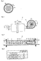
Fig.1 is a piping system diagram of the present invention. -
Fig.2 is a cross-sectional view taken on line X-X ofFig.4 showing the ballast water treatment equipment of the present invention in operation. -
Fig.3 is a cross-sectional view taken on line Y-Y ofFig.2 . -
Fig.4 is a fragmentary cross-sectional view taken on line Z-Z ofFig.2 . -
Fig.5 is a schematic cross- sectional view of AC electrolysis apparatus used in the present invention. -
Fig.6 is a table showing the result of decomposition and volatilization of the fungicide by the nano bubbles generation equipment for ballast water. - Hereinafter, preferred embodiments of a ballast water detoxifying treatment system A of the present invention will be concretely described. The system A can be applied to ballast water feed and drainage equipment of a ship, cooling equipment of a power plant, or the like. The case that the system A is applied to the ballast water feed and drainage equipment of a ship is described as follows. When the system is applied to the cooling equipment of a power plant, "a ship", "a ballast tank" , and "ballast water" are substituted to "a power plant", "a cooling water tank", and "cooling water", respectively.
- A
ballast tank 1 is a tank for storingballast water 2 and arranged from bow side to stem side of a ship. To keep balance of the ship, the inside of theballast tank 1 is separated through the length and breadth byseparate walls 111 and volume of theballast water 2 storaged in theballast tank 1 is controlled by ballast water distributer (not shown). - An inlet opening 6 and a
drainage opening 12 are arranged at alongside of the ship. Anintake pipe 7 connects the inlet opening 6 to theballast tank 1. A filtering device for intake F1 is put in the inlet opening 6 of theintake pipe 7 or adjacent to. And a high pressure pump 9, afungicide adding device 4, ballastwater treatment equipment 3 are arranged in a row and in this order. A water pumping up pipe 17 is connected to a diverging point P1 on theintake pipe 7 between the filtering device for intake F1 and the high pressure pump 9. Accordingly, theballast water 2 in theballast tank 1 can be pumped up to the high pressure pump 9. A changeover valve R1 (comprises two valves R1a and R1b) is arranged on the diverging point P1. The ballastwater treatment equipment 3 is put in downstream of the high pressure pump 9. Thefungicide adding device 4 is put in downstream of the ballastwater treatment equipment 3. Theintake pipe 7 divaricated from thefungicide adding device 4 is connencted to theballast tank 1. And adrainage pipe 11 divaricated from a diverging point P2 between the ballastwater treatment equipment 3 and thefungicide adding device 4 is connected to thedrainage opening 12. A changeover valve R2 (comprises two valves R2a and R2b) is arranged on the diverging point P2. A filtering device for drainage F2 is arranged at thedrainage opening 12 or arranged near theopening 12. And a fungicide removing device 16 is put in thedrainage pipe 11 at upstream of the filtering device for drainage F2. Activated carbon or the like is suitable as filled material for the fungicide removing device 16, because the activated carbon can adsorb the residual fungicide passed through the decomposition treatment with the ballastwater treatment equipment 3 before draining to sea. - The changeover valves R1, R2 are for changing over the directon of water flow. For the changeover valves R1-R3, three-way electromagnetic valves are used. In illustrated embodiment, as described above, two pairs of valves Ra1-R1b, R2a-R2b perforing same operation as the changeover valves R1, R2 are arranged near the diverging pints P1, P2, respectively. The valve R1a is put between the filtering device F1 near the inlet opening 6 and the the diverging point P1. The valve R1b is put in the water pumping up pipe 17. The valve R2a is put between the
fungicide adding device 4 and the diverging point P2. And the valve R2b is put in thedrainage pipe 11. - The filtering device for intake F1 comprises a coarse filtering part and a fine filtering part. Bulk material such as trash in the
ballast water 2 taken from the inlet opening 6 at alogside of the ship and the aquatic creatures such as jelly fish, seaweed, or the like are removed in the coarse filtering part. And a part of phytoplankton and animal plankton in theballast water 2 is filtered in the fine filtering part. In the similar manner, trash or the like in theballast water 2 pumped from theballast tank 1 is filtered in the filtering device for drainage F2. - The ballast
water treatment equipment 3 which is put in downstream of the high pressure pump 9 comprises ashear flow generator 31 in entry-side and aswirl flow generator 37 having a cylindricalmain body 37a and adiffuser pipe 38 connected to an outlet of the cylindricalmain body 37a. One embodiment is illustrated inFig.2 to Fig.4 . Theshear flow generator 31 comprises ananterior chamber 31 a, aposterior chamber 31b having a plural of paralleled venturi tubes withrecesses 33 internally, and a connectingpipe 36 connecting theposterior chamber 31b to theswirl flow generator 37. Theanterior chamber 31a is connected to theintake pipe 7 from the high pressure pump 9. And theanterior chamber 31 a is a cylinder with bottom face having expanded inner diameter for covering entry-openings 34 of the plural of paralleled venturi tubes withrecesses 33. Theintake pipe 7 is connected to the bottom face of theanterior chamber 31 a. Open side of theanterior chamber 31 a is coupled with theposterior chamber 31b with flange connection. - The
posterior chamber 31b is also a cylinder with bottom face. The plural of parralleled venturi tubes withrecesses 33 is inserted through apartition plate 31c oppilating an inlet opening of theposterior chamber 31b. One end of the connectingpipe 36 is connected to the bottom face (adownstream side face 31d), and the other end of the connectingpipe 36 is connected aslant to outer surface on outlet side of the cylindricalmain body 37a. For example, the other end of the connectingpipe 36 is connected "tangentially" to the outer surface on outlet side of the cylindricalmain body 37a. - Each of the venturi tubes with
recesses 33 comprises athroat 33b being short and small cylinder, an inlet side cross-sectionalarea reducing part 33a having a polygonal shaped entry-opening 34, an outlet side cross-sectionalarea enlarging part 33c, and a shearflow generating recess 33d opening to thethroat 33b. The cross-sectional shape of the inlet side cross-sectionalarea reducing part 33a is a streamline shape of which diameter is gradually reduced from the entry-opening 34 to thethroat 33b and cross-sectional shape is transformed from the polygon to circularity. In addition, the reason that the entry-opening 34 is polygonal shape is to arrange each of the entry-openings 34 adjacently not to create a flat part which is in a direction perpendicular to the flow and generates flow resistance. Triangle, square, pentagon, and hexagon can be selected as the plygonal shape. In this embodiment, the pentagon shaped entry-openings 34 are arranged to make honeycomb in shape. The shape of the entry-opening 34 may be circularity. However, the circularity shaped entry-openings 34 make the flat part which generates flow resistance. Accordingly, the flat part generates pressure loss in theanterior chamber 31 a. The diameter of the outlet side cross-sectionalarea enlarging part 33c is enlarged from the thoat 33b to outlet opening. The shearflow generating recess 33d is disc-shaped space opening on entire circumference of thethroat 33b. By adjusting width and depth of the shearflow generating recess 33d, nano bubbles can be generated, when the all ofballast water 2 is passing through thethroat 33b. - The
swirl flow generator 37 comprises the cylindricalmain body 37a, adiffuser pipe 38 connected to outlet openinig of the cylindricalmain body 37a, and anouter air supplier 39 provided as necessary. Theouter air supplier 39 comprises apipe 39 connected to center of anupper face 37c of the cylindricalmain body 37a, anouter air valve 39a put in thepipe 39, and an outerair supplying pump 39b. If inside of theswirl flow generator 37 is in negative pressure during operation, naturally-aspirated outer air can be supplied through thepipe 39c without using the outerair supplying pump 39b. Thepipe 39 is arranged along a central axis of the cylindricalmain body 37a. And the outer air is supplied through thepipe 39c into the cylindricalmain body 37a. In this embodiment, onepipe 39c is connceted to an opening for air supply on theupper face 37c. A plural of thepipes 39c may be connected to a plural of the openings for air supply. - The
diffuser pipe 38 is provided from center ofbottom face 37b on outlet side of the cylindricalmain body 37a. And inside of thediffuser pipe 38 is shaped as a smooth cone (not shown), one step (not shown), ormultistep diffuser 38a-38c with circularity cross-section shape (as shown inFig.1 andFig.3 ) of which each diameter is gradually enlarged along the flow. And thediffuser pipe 38 is connceted to theintake pipe 7. - In this embodiment, one ballast
water treatment equipment 3 is provided. However, a plural of the ballastwater treatment equipment 3 may be provided in parallel depending on the amount of the ballast water to be treated. Furthermore, a plural of the ballastwater treatment equipment 3 may also be provided in series for multiple treatment. An appropriate number of the venturi tubes withrecesses 33 is selected. If one venturi tube withrecess 33 is used, theintake pipe 7 and the connectingpipe 36 are connected directly to the entry-opening 34 and the outlet opening 35 of the venturi tube withrecess 33, respectively. - Here, dechloridation in drainage and damaging the aquatic creatures or the like in the ballast
water treatment equipment 3 in water intake are explained as follows. Theballast water 2 is pumped up from theballast tank 1 and pressed into thethroat 33b through the inlet side sectionalarea reducing part 33a rapidly by the high pressure pump 9. Strong shear flow is generated in the shearflow generating recess 33d by rapid expansion of the pressedballast water 2. As a result, a large number of nano bubbles are generated with concentration and open of energy using fluid resonance phenomenon in the shearflow generating recess 33d. The nano bubbles have strong surface tension and exist with nearly zero volume in theballast water 2. A part of the large number of nano bubbles is expanded (rebound) rapidly with decrease of pressure in the outlet side cross-sectionalarea enlarging part 33c. And blowout after rapid shrink in size of the part of nano bubbles in the term of rapid rebound of the pressure generates microjets and impact waves. The residual nano bubbles flow into theswirl flow generator 37 through theposterior chamber 31b and the connectingpipe 36. - The
ballast water 2 including the fungicide and a large number of residual nano bubbles flow aslant into theswirl flow generator 37 through the connectingpipe 36 at high velocity. And theballast water 2 flows in a direction of thediffuser pipe 38 as the outlet of theswirl flow generator 37 as gyrating at high velocity. As a result, strong swirl flow is generated at this time. Consequently, with the centrifugal force of high velocity swirl, pressure at outer circumference of cylindricalmain body 37a becomes higher than that at central part. - In addition, there are two cases for supplying the outer air. One case is that the outer air is suctioned through the
outer air supplier 39 into theswirl flow generator 37. The other case is that the outer air is not suctioned into. In latter case, the pressure at central part of the cylindricalmain body 37a decreases. On the other hand, the outer air suction causes little pressure drop and generation of a large number of MN bubbles (micro-nano bubbles made of air). Sufficiently-low pressure at the central part of the cylindricalmain body 37a generates natural suction, and insufficiently-low pressure needs forced suction by the outerair supplying pump 39b. - In the forced suction, opening the
outer air valve 39a of theouter air supplier 39 and pressing the outer air from the outerair supplying pump 39b in operation (or natural suction of the outer air) into theswirl flow generator 37 makes gas-liquid mixing water mixed the air and theballast water 2 including the fungicide with a large number of bubbles at outlet of thepipe 39c. And the mixed water flows with the swirl flow from the connectingpipe 36 to outlet substantially along center axis of theouter air supplier 39 as swirling. - Difference in specific gravity between relatively-large size bubbles of the suction air and liquid of the
ballast water 2 including the fungicide causes a certain level of gas-liquid separation by the centrifugal force affected to the liquid and the centripetal force affected to the bubbles. Then the large number of separated bubbles flows in the direction of outlet as changing its diameter and taking on a cord in shape. In the meanwhile, a part of bubbles is sheared and teared apart by the swirl flow of high velocity swirling liquid. Consequently, fine bubbles, including nano bubbles, are generated in large numbers and are diffused rapidly in the cylindricalmain body 37a. - In the case that the outer air is not suctioned, a large number of residual nano bubbles from the venturi tube with
recess 33 are enlarged (rebound) to micro-nano bubbles at low pressure part in the swirl flow. - Furthermore, after compressed at the
outlet opening 37d, enlargement of nano bubbles to micro-nano bubbles, acceleration of generation of cavitation by blowout of the micro-nano bubbles, and generating strong turbulence are arised by decrease of water pressure with rapid re-expansion in thediffuser pipe 38. In case that thediffuser pipe 38 is one ormultistep diffuser 38a-38c, decrease of water pressure by one or multiple rapid stepwise expansion when theballast water 2 passes through thediffuser pipe 38 at inner circumference surface causes acceleration of generation of cavitation and generating strong turbulence at corners. Then theballast water 2 flows into the intake pipe 7 (in downstream side). In this period, continuous blowout of a large number of the micro-nano bubbles generates impact pressure (a phenomenon that one side surface of the bubble sticks out to the other side surface like a lance with generation of high pressure at the blowout) which is stronger than that in the outlet side cross-sectionalarea enlarging part 33c and in the cylindricalmain body 37a, shear stress, heat, and chemical action such as OH-radical i.e. radical oxygen with strong oxidation power. Then a part of ClO- of sodium hypochlorite (NaClO) in theballast water 2 is decomposed and detoxified. Aeration by outer air suctioning in theswirl flow generator 37 contributes removal of decomposition products (seeFig.6 ). This point is the same as in water intake. After breaking and damaging outer shell of protozoa which have comparatively hard shell and animal plankton, the fungicide added subsequently eliminates the aquatic creatures and fungi easily. - As described above, in the ballast
water treatment equipment 3, rapid enlargement of nano bubbles to larger than micro-nano bubbles and chain of bubble blowout generate the field (cascade) with chain of microjet and impact wave at the cascade field (to be described) from the venturi tube withrecess 33 to thediffuser pipe 38. - The cascade field is defined as a rapid pressure fluctuation field where overwhelming cavitation with intervention of a large number of nano bubbles is occurred. In this embodiment, the cascade field is rapidly changed from positive pressure field where is affected the centrifugal force of the swirl flow in circumference area of the cylindrical
main body 37a to negative pressure field where is decreased the water pressure from the central part of the swirl flow to thediffuser pipe 3 8. The cascade field is a field towards a negative field where is decreased the water pressure from the outlet side cross-sectionalarea enlarging part 3 3 c to theposterior chamber 31b and the connectingpipe 36 after generating a large number of nano bubbles in the shearflow generating recess 33d. - In addition, the cavitation (otherwise known as ambient temperature boiling phenomenon) has a hard erosion behavior (cavitation erosion) which can erode metal faces and generates finally hundreds of meters per second in velocity of strong microjets and impact waves by asymmetricity shrink with strong interference in the course of deterioration at pressure decreasing field. The impact waves eliminate the aquatic creatures and fungi living around and reinforces the chain of blowout of the other bubbles. Furthermore, the impact waves detoxify the (ClO-) electrochemically and physicochemically (see
Fig.6 ). - The
fungicide adding device 4 put in downstream of the ballastwater treatment equipment 3 is to add sufficient quantity of fungicide for eliminating the aquatic creatures or the like barely managed to survive after passing through the cascade field of the ballastwater treatment equipment 3 for up to 5 days (IMO standard). Thefungicide adding device 4 adds appropriate quantities of sodium hypochlorite to theballast water 2, or produces sodium hypochlorite by electrolysis of theballast water 2. In this embodiment, sodium hypochlorite is used as an example of the fungicide and AC electrolysis apparatus is used as an example of thefungicide adding device 4. Three electrodes (one of them is for ground electrode, the remains are for anode electrode and cathode electrode, respectively [Triode AC type]. Or else, no ground electrode and a pair of anode and cathode electrodes [bipolar electrodes AC type].) is treated as one pair. And one or several pairs of the three electrodes are used for theAC electrolysis apparatus 4. In this embodiment, the triode AC type is explained as an example. - The
AC electrolysis apparatus 4 is an inline type in this embbodiment and has a double structure comprising aninner pipe 42 and aouter pipe 43. And electrodes 41 a-41 c are fixed between theinner pipe 42 and theouter pipe 43 to pass all amount of theballast water 2 around theelectrodes 41a-41c. Theelectrodes 41a-41c are perforated-plates (e.g. expanded metals, perforated metal) made of titanium or strainless steel and plated with platinum. Theelectrodes 41a-41c are arranged at regular intervals (equal intervals) at outlet end of theinner pipe 42. Furthermore, outer surfaces of theseelectrodes 41a-41c have contact with an inner surface of theouter pipe 43. Accordingly, theballast water 2 passing between theouter pipe 43 and theinner pipe 42 totally passes through a reticulation constructed by theelectrodes 41a-41c. Theouter pipe 43 is connected to theintake pipe 7. - From entry opening to central part, the
inner pipe 42 has many throughholes 44 through which water passes.Support 45 is arranged three-way radially near the entry opening between theinner pipe 42 and theouter pipe 43 for suspending theinner pipe 42 at center of theouter pipe 43. In inside of theinner pipe 42, closingplates inner pipe 42, and between the end of theinner pipe 42 and the throughhole 44 nearest the end, respectively. Electric wires connecting theelectrodes 41a-41c tocontroller 15 is guided out through a support pipe 48 which is put in near the end of theouter pipe 43 between theinner pipe 42 and theouter pipe 43 and suspends theinner pipe 42 at center of theouter pipe 43. - In this embodiment, one
AC electrolysis apparatus 4 is used. However, severalAC electrolysis apparatuses 4 in parallel or in series may be used as appropriate. In addition, theinner pipe 42 is provided to support theelectrodes 41a-41c in this embodiment. But theinner pipe 42 may not be necessary, when theelectrodes 41a-41c can be fixed on inner surface of theouter pipe 43. - The embodiment explained as above is operated as follows. At unloading port, the
ballast water 2 is taken into theballast tank 1 against too much uplift of unloaded ship. In water intake, the valve R1b, R2b are closed, and the valve R1a, R2a are opened. Then the seawater is taken from the intake opening 6 by the high pressure pump 9. At this time, bulk material and bulk aquatic creatures (phytoplankton, animal plankton or the like) are removed from theballast water 2 by the filtering device for intake F1. And these filtered objects are returned to the sea of the unloading port by reverse washing. - After passing through the filtering device for intake F1, the
ballast water 2 is supplied totally to the nano bubbles generating equipment (ballast water treatment equipment) 3 by the high pressure pump 9 through theintake pipe 7. In theswirl flow generator 37 of the ballastwater treatment equipment 3, the outer air is supplied as necessary to theballast water 2 by opening theouter air valve 39a and operating the outerair supplying pump 39b, or natural suction. Then an infinite number of fine nano bubbles and micro-nano bubbles (enlarged nano bubbles) are generated in the ballastwater treatment equipment 3 by the workings as described above. By blowing out the micro-nano bubbles rapidly, all or almost all the aquatic creatures or the like in theballast water 2 are damaged (i.e. eliminated and injured). In addition, the effect of the cavitation may only be used by closing theouter air valve 39a in intake and drainage of theballast water 2. All or almost all the aquatic creatures or the like in theballast water 2 are eliminated and injured during theballast water 2 passes through the cascade field in the ballastwater treatment equipment 3. In thefungicide adding device 4 downstream of the ballastwater treatment equipment 3, minimum amount of sodium hypochlorite (to be 3 mg/liter of chlorine) for eliminating the injured aquatic creatures or the like for up to 5 days in theballast tank 1 is added in a state of mixed with thesea water 2. After that, theballast water 2 is supplied to theballast tank 1. In theballast tank 1, the injured aquatic creatures or the like is eliminated by chlorine. And the concentration of chlorine is decreased to approximately 1 mg/liter, because the chlorine is consumed. The residual chlorine inhibits re-activation and reproduce of residual aquatic creatures or the like. - In loading at the next wayport, the
ballast water 2 corresponding to weight of load is drained. In drainage, theballast water 2 in theballast tank 1 is pumped up by the high pressure pump 9 after closing the valve R1a,R2a and opening the valve R1b, R2b. The residual chlorine in the pumpedballast water 2 is decomposed by passing through the ballastwater treatment equipment 3 and is adsorbed by the activated carbon in the residual fungicide removing device 16. After filtered by the filtering device for drainage F2, theballast water 2 is drained to the sea. -
Fig.6 shows test data indicating decomposition of residual chlorine with the nano bubble generating device of the present invention. The test simulates the decomposition of residual chlorine in drainage. The data shows that it was required more then 12 mg/liter of the chlorine concentration for eliminating the aquatic creatures or the like for up to 5 days by adding only sodium hypochlorite without using the nano bubble generating device. However, at least 3 mg/liter (at the time of adding) of the concentration was enough for eliminating for up to 5 days with using the nano bubble generating device. And the concentration of the residual free chlorine in theballast tank 1 after five days was 1 mg/liter. The residual free chlorine was measured by a residual chlorine measuring instrument (manufactured by Technoecho co, Ltd.). "Residual free chlorine" is defined as chlorine gas (Cl2), hypochlorous acid (HOCl), and hypochlorite ion (OCl-) existing in the test water (sea water in the ballast tank 1). - The concentration of salt of sea water for the test was 3.64 mg/liter, temperature of the sea water was 4.3 °C, temperature of test atmosphere was 7 °C, moisture content of the atomosphere was 42 %, and concentration of residue chlorine was 1.0 mg/liter. The sea water was pumped up by the high pressure pump and passed through the nano
bubble generating device 3 in a flow rate of 138 liter/min. - For the nano
bubble generating device 3, one stage diffuser pipe and two stage diffuser pipe were provided. The test was conducted in case without supplying outer air from theouter air supplier 39 to thecylinder 37a (without outer air) and in case with suppling (with outer air). The number of the venturi tubes withrecesses 33 for the nanobubble generating device 3 was fifteen. - According to result of the test shown in
Fig.6 , the dechloridation was established in each case. Especially, in case that using one stage diffuser (with outer air) was the best, because the concentration of residual chlorine was 0.6 mg/liter (this meant that 0.4 mg/liter of sodium hypochlorie had been decomposed.). Therefore, using the nanobubble generating device 3 of the present invention makes drastic reduction of the activated carbon usage for adsorbing chlorine in drainage, and reductio of the sodium hypochlorite usage for damaging heavily the aquatic creatures or the like in water intake.
Claims (5)
- Ballast water treatment equipment 3 for supplying ballast water 2 to a ballast tank 1 through a fungicide adding device 4, comprising:a shear flow generator 31 put in an intake pipe 7 from an intake opening 6 to the ballast tank 1, and receiving ballast water 2 from a high pressure pump 9; anda swirl flow generator 37 connected to downstream of the swirl flow generator 37 with a connecting pipe 36;wherein the shear flow generator 31 has one or more venturi tubes with recesses 33 arranged in parallel;each the venturi tube with recess 33 comprises an inlet side cross-sectional area reducing part 33a gradually decreasing sectional area along a flow direction; an outlet side cross-sectional area enlarging part 33c put in downstream of the inlet side cross-sectional area reducing part 33a, and increasing cross-sectional area along the flow direction; a throat 33b put between the inlet side cross-sectional area reducing part 33a and the outlet side cross-sectional area enlarging part 33c; and a shear flow generating recess 33d opening to the throat 33b;wherein the swirl flow generator 37 has a cylinder 37a being aslant connected the connecting pipe 36 of the shear flow generator 31 to its outer lateral surface; and a diffuser pipe 38 having an inner circumference surface increasing cross-sectional area along the flow direction and connected to the fungicide adding device 4 through an intake pipe 7.
- The ballast water treatment equipment 3 according to claim 1, wherein the diffuser pipe 38 is one step or multistep diffuser 38a-38c having a tier-expanded inner surface expanding along the flow direction.
- The ballast water treatment equipment 3 according to claim 1, wherein the swirl flow generator 37 has an outer air supplier 39 on a center of an upper face 37c of the cylinder 37a.
- A ballast water detoxifying treatment system A, comprising:a ballast tank 1 storing ballast water 2;an intake pipe 7 connecting a water intake opening 6 and the ballast tank 1;a high pressure pump 9 put in the intake pipe 7;the ballast water treatment equipment 3 according to claim 1 put in downstream of the high pressure pump 9;a fungicide adding device 4 put in downstream of the ballast water treatment equipment 3, and adding fungicide to the ballast water 2 supplied from the ballast water treatment equipment 3;a water pumping up pipe 17 connecting the ballast tank 1 to the intake pipe 7 upstream of the high pressure pump 9;a drainage pipe 11 diverged from the intake pipe 7 at downstream of the ballast water treatment equipment 3;a residual fungicide removing device 16 put in the drainage pipe 11;a changeover valve R1 put in near a diverging point P1 between the intake pipe 7 and the water pumping up pipe 17, and changing over intake and drainage; anda changeover valve R2 put in near a diverging point P2 between the intake pipe 7 and the drainage pipe 11, and changing over intake and drainage.
- A method for treating the ballast water using the ballast water detoxifying treatment system A according to claim 4, comprising:in supplying ballast water 2 to a ballast tank 1,filtering the ballast water 2;passing through the filtered ballast water 2 to the ballast water treatment equipment 3 according to claim 1; andsupplying the ballast water 2 to the ballast tank 1 after adding fungicide,in draining the ballast water 2 from the ballast tank 1,pumping up the ballast water 2 from the ballast tank 1 to the ballast water treatment equipment 3;removing the residual fungicide in the ballast water 2 with activated carbon; anddraining.
Applications Claiming Priority (1)
| Application Number | Priority Date | Filing Date | Title |
|---|---|---|---|
| PCT/JP2010/001575 WO2011108032A1 (en) | 2010-03-05 | 2010-03-05 | Ballast water treatment device, system for rendering ballast water harmless using the device, and method therefor |
Publications (3)
| Publication Number | Publication Date |
|---|---|
| EP2476652A1 true EP2476652A1 (en) | 2012-07-18 |
| EP2476652A4 EP2476652A4 (en) | 2014-02-26 |
| EP2476652B1 EP2476652B1 (en) | 2015-09-16 |
Family
ID=44541720
Family Applications (1)
| Application Number | Title | Priority Date | Filing Date |
|---|---|---|---|
| EP10825825.2A Active EP2476652B1 (en) | 2010-03-05 | 2010-03-05 | Ballast water treatment system and method |
Country Status (6)
| Country | Link |
|---|---|
| US (1) | US8557122B2 (en) |
| EP (1) | EP2476652B1 (en) |
| JP (1) | JP5551585B2 (en) |
| KR (1) | KR101677479B1 (en) |
| DK (1) | DK2476652T3 (en) |
| WO (1) | WO2011108032A1 (en) |
Cited By (1)
| Publication number | Priority date | Publication date | Assignee | Title |
|---|---|---|---|---|
| CN110773115A (en) * | 2019-11-20 | 2020-02-11 | 苏州溪能环保科技有限公司 | A high-efficiency water treatment device |
Families Citing this family (18)
| Publication number | Priority date | Publication date | Assignee | Title |
|---|---|---|---|---|
| US9688551B2 (en) | 2012-06-18 | 2017-06-27 | The United States Of America As Represented By The Secretary Of The Interior | Nozzle mixing apparatus and methods for treating water in ship ballast tanks |
| KR101306596B1 (en) * | 2013-05-23 | 2013-09-10 | 삼건세기(주) | Ballast water treatment system |
| JP5892208B2 (en) * | 2014-07-30 | 2016-03-23 | 三菱電機株式会社 | Microbubble generator |
| JP2016104474A (en) | 2014-08-22 | 2016-06-09 | 有限会社情報科学研究所 | Ultrafine bubble manufacturing method and ultrafine bubble water manufacturing device by resonance forming and vacuum cavitation |
| JP2016203082A (en) * | 2015-04-21 | 2016-12-08 | 沖野 晃俊 | Method for producing radical functional liquid and purification method using radical functional liquid |
| JP6043900B1 (en) * | 2016-02-12 | 2016-12-14 | 有限会社情報科学研究所 | Ultra fine bubble aqua jet device with internal combustion engine. |
| JP6615662B2 (en) * | 2016-03-18 | 2019-12-04 | 株式会社ノリタケカンパニーリミテド | Apparatus for producing bubble-containing liquid and method of using the same |
| JP6230738B1 (en) * | 2016-09-01 | 2017-11-15 | 株式会社晃和工業 | Perforated nozzle for killing harmful enemy aquatic creatures |
| KR20190126768A (en) * | 2016-12-15 | 2019-11-12 | 마이클 스미스 | Systems and Methods for Creating Cavitation in Fluid |
| KR102666811B1 (en) | 2016-12-16 | 2024-05-20 | 엘지전자 주식회사 | Fine-bubble generating system |
| US10240243B2 (en) * | 2017-05-05 | 2019-03-26 | Hamilton Sundstrand Corporation | Flow distributor hole pattern |
| CN110678385A (en) * | 2017-05-30 | 2020-01-10 | 日本邮船株式会社 | Ballast water system |
| JP6960281B2 (en) * | 2017-09-05 | 2021-11-05 | 株式会社富士計器 | Fine bubble liquid generator |
| WO2019069349A1 (en) * | 2017-10-02 | 2019-04-11 | Hack Japan ホールディングス株式会社 | Bubble generating device and bubble generating method |
| JPWO2019069350A1 (en) * | 2017-10-02 | 2020-10-22 | Hack Japan ホールディングス株式会社 | Bubble generation device, bubble generation method |
| WO2021096917A1 (en) * | 2019-11-14 | 2021-05-20 | ACUDX Inc. | Emulsification device and emulsification method |
| KR102539609B1 (en) * | 2022-08-04 | 2023-06-02 | 에스엔시스(주) | A sterilization filteration apparatus with bubble generator and a ballast water management system using the same |
| CN117268846A (en) * | 2023-10-09 | 2023-12-22 | 中船澄西船舶修造有限公司 | An air intake mechanism for anti-negative pressure ballast water sampling system |
Family Cites Families (36)
| Publication number | Priority date | Publication date | Assignee | Title |
|---|---|---|---|---|
| JPS6319569A (en) | 1986-07-14 | 1988-01-27 | Toyo Commun Equip Co Ltd | Method for detecting leaked current |
| JP2623204B2 (en) | 1993-02-26 | 1997-06-25 | 英雄 早川 | Water reforming method |
| AU2513995A (en) * | 1994-07-13 | 1996-02-16 | Angelo L. Mazzei | Gas injection into liquid and removal of undissolved gas |
| US5951923A (en) | 1996-05-23 | 1999-09-14 | Ebara Corporation | Vaporizer apparatus and film deposition apparatus therewith |
| JPH1074746A (en) | 1996-05-23 | 1998-03-17 | Ebara Corp | Liquid raw material vaporizer |
| JPH108255A (en) | 1996-06-20 | 1998-01-13 | Ebara Corp | Liquid raw material vaporizing device |
| US5865995A (en) * | 1997-04-02 | 1999-02-02 | Nelson; William R. | System for treating liquids with a gas |
| US5863128A (en) * | 1997-12-04 | 1999-01-26 | Mazzei; Angelo L. | Mixer-injectors with twisting and straightening vanes |
| JP3650543B2 (en) | 1999-07-01 | 2005-05-18 | 株式会社リンテック | Vaporizer |
| KR100412307B1 (en) * | 2001-05-23 | 2003-12-31 | 주식회사두합크린텍 | Apparatus for making minute bubbles and method of making therof |
| US20030015481A1 (en) * | 2001-06-28 | 2003-01-23 | Eidem Ola Magne | Method and apparatus for treating/disinfecting ballast water in ships |
| JP3763521B2 (en) * | 2001-10-26 | 2006-04-05 | 株式会社オ−ラテック | Micro bubble generator |
| EP1499563B9 (en) * | 2002-05-02 | 2014-03-05 | McNulty, Peter, Drummond | Apparatus and method of ballast water treatment |
| JP2005144320A (en) * | 2003-11-14 | 2005-06-09 | Yamato:Kk | Fluid mixing apparatus |
| US20080164217A1 (en) * | 2004-02-13 | 2008-07-10 | Kazuki Nishizawa | Method of Liquid Detoxification and Apparatus Therefor |
| WO2006003723A1 (en) * | 2004-07-05 | 2006-01-12 | Daiki Ataka Engineering Co., Ltd. | Method of treating ballast water and treating apparatus therefor |
| JP2006088115A (en) * | 2004-09-27 | 2006-04-06 | Kurita Water Ind Ltd | Ballast water treatment method and apparatus |
| US7624969B2 (en) * | 2004-09-30 | 2009-12-01 | Justin Schletz | Two-stage injector-mixer |
| JP2006212513A (en) * | 2005-02-02 | 2006-08-17 | Ishikawajima Harima Heavy Ind Co Ltd | Ballast water purification equipment |
| JP4085093B2 (en) * | 2005-02-14 | 2008-04-30 | 三井造船株式会社 | Ballast water treatment equipment |
| US7776224B2 (en) * | 2005-06-10 | 2010-08-17 | Jfe Engineering Corporation | Apparatus for treating ballast water and method for treating ballast water |
| JP4844244B2 (en) | 2005-06-10 | 2011-12-28 | Jfeエンジニアリング株式会社 | Ballast water treatment apparatus and treatment method |
| JP5034210B2 (en) * | 2005-10-14 | 2012-09-26 | Jfeエンジニアリング株式会社 | Ballast water treatment equipment |
| JP4978002B2 (en) * | 2005-12-07 | 2012-07-18 | Jfeエンジニアリング株式会社 | Ballast water treatment method |
| JP2007069071A (en) * | 2005-09-05 | 2007-03-22 | Sharp Corp | Fine bubble generator and fine bubble circulation system incorporating the same |
| US20100181260A1 (en) * | 2005-10-28 | 2010-07-22 | Resource Ballast Technologies (Proprietary) Limited | Method and Apparatus for Water Treatment to Eliminate Aquatic Organisms |
| JP3890076B1 (en) * | 2006-02-03 | 2007-03-07 | 修 松本 | Bubble generator |
| JP4272669B2 (en) * | 2006-09-29 | 2009-06-03 | 社団法人日本海難防止協会 | Ship ballast water treatment equipment |
| JP4099200B2 (en) * | 2006-10-17 | 2008-06-11 | 東フロコーポレーション株式会社 | Gas-liquid mixing device |
| JP2008114099A (en) * | 2006-10-31 | 2008-05-22 | Sanyo Facilities Industry Co Ltd | Microbubble generation device and bubble fining implement |
| JP4370342B2 (en) * | 2007-03-30 | 2009-11-25 | 大晃機械工業株式会社 | Processing equipment for underwater fines |
| JP5132229B2 (en) * | 2007-09-13 | 2013-01-30 | Jfeエンジニアリング株式会社 | Venturi pipe device and ballast water treatment apparatus using the venturi pipe device |
| JP2008100225A (en) * | 2007-11-02 | 2008-05-01 | Toflo Corporation Kk | Gas-liquid mixing device |
| JP2009136864A (en) | 2007-11-16 | 2009-06-25 | Nippon Sozai Kk | Micro bubble generator |
| JP5269493B2 (en) * | 2008-06-18 | 2013-08-21 | 佐藤工業株式会社 | Micro bubble generator |
| KR20100006610A (en) * | 2008-07-10 | 2010-01-21 | 장학정 | Hot water heater using vortex fluid |
-
2010
- 2010-03-05 EP EP10825825.2A patent/EP2476652B1/en active Active
- 2010-03-05 DK DK10825825.2T patent/DK2476652T3/en active
- 2010-03-05 US US12/677,032 patent/US8557122B2/en active Active
- 2010-03-05 WO PCT/JP2010/001575 patent/WO2011108032A1/en not_active Ceased
- 2010-03-05 KR KR1020127023001A patent/KR101677479B1/en active Active
- 2010-03-05 JP JP2010510003A patent/JP5551585B2/en active Active
Cited By (2)
| Publication number | Priority date | Publication date | Assignee | Title |
|---|---|---|---|---|
| CN110773115A (en) * | 2019-11-20 | 2020-02-11 | 苏州溪能环保科技有限公司 | A high-efficiency water treatment device |
| CN110773115B (en) * | 2019-11-20 | 2022-07-12 | 苏州溪能环保科技有限公司 | A high-efficiency water treatment device |
Also Published As
| Publication number | Publication date |
|---|---|
| EP2476652B1 (en) | 2015-09-16 |
| KR101677479B1 (en) | 2016-11-18 |
| US8557122B2 (en) | 2013-10-15 |
| KR20130051433A (en) | 2013-05-20 |
| US20120318751A1 (en) | 2012-12-20 |
| JPWO2011108032A1 (en) | 2013-06-20 |
| DK2476652T3 (en) | 2015-12-14 |
| EP2476652A4 (en) | 2014-02-26 |
| JP5551585B2 (en) | 2014-07-16 |
| WO2011108032A1 (en) | 2011-09-09 |
Similar Documents
| Publication | Publication Date | Title |
|---|---|---|
| US8557122B2 (en) | Ballast water treatment equipment, a ballast water detoxifying treatment system using the same, and a method for treating the ballast water | |
| CN100427409C (en) | Apparatus and method for treating ballast water by electrolysis using natural seawater | |
| RU2433087C2 (en) | Method of disinfecting water by destroying aquatic organisms and apparatus for realising said method | |
| US20150307372A1 (en) | Apparatus and method for treating ballast water | |
| US20090321260A1 (en) | Liquid treatment methods and apparatus | |
| JP2010524678A (en) | Water treatment system | |
| EP2539220B1 (en) | Method and device for treatment of water | |
| JP4737157B2 (en) | Ballast water treatment apparatus and ballast water treatment method | |
| JP4915313B2 (en) | Ballast water treatment equipment | |
| US10287200B2 (en) | Method for treating ballast water and device for treating ballast water used therefor | |
| JP2006263563A (en) | Device for killing microorganisms in ballast water | |
| EP4566938A1 (en) | Sterile filtration device provided with bubble generator, and ship ballast water treatment system using same | |
| KR102187152B1 (en) | Ballast water treatment equipment | |
| CN216890228U (en) | Ballast water cyclone separator | |
| US20140042088A1 (en) | Bubble generating system and method for wastewater treatment | |
| KR102369944B1 (en) | Micro bubble nozzle and micro bubble generator comprising same | |
| JP6593814B2 (en) | Hydrogen removal tank and ballast water treatment system having the same | |
| KR101865896B1 (en) | High efficiency ballast water management system | |
| KR20110114931A (en) | Performance Enhancement Device of Electrolysis Method Ballast Water Treatment System Using Ultrasonic Excitation Device | |
| KR100733541B1 (en) | Electrolytic Ballast Water Treatment Method and Treatment Apparatus | |
| CN204714623U (en) | A kind of apparatus for treating ship ballast water | |
| WO2012098466A1 (en) | Bubble generating system and method for wastewater treatment | |
| AU2012203894B2 (en) | Ballast water treatment methods and apparatus | |
| US20160039689A1 (en) | Liquid treatment method and liquid treatment device used therein | |
| CN104925985A (en) | Vessel ballast water treatment device |
Legal Events
| Date | Code | Title | Description |
|---|---|---|---|
| PUAI | Public reference made under article 153(3) epc to a published international application that has entered the european phase |
Free format text: ORIGINAL CODE: 0009012 |
|
| AK | Designated contracting states |
Kind code of ref document: A1 Designated state(s): AT BE BG CH CY CZ DE DK EE ES FI FR GB GR HR HU IE IS IT LI LT LU LV MC MK MT NL NO PL PT RO SE SI SK SM TR |
|
| 17P | Request for examination filed |
Effective date: 20120727 |
|
| DAX | Request for extension of the european patent (deleted) | ||
| A4 | Supplementary search report drawn up and despatched |
Effective date: 20140123 |
|
| RIC1 | Information provided on ipc code assigned before grant |
Ipc: C02F 1/467 20060101ALN20140117BHEP Ipc: B01F 5/04 20060101ALI20140117BHEP Ipc: C02F 1/50 20060101ALI20140117BHEP Ipc: C02F 1/00 20060101ALI20140117BHEP Ipc: C02F 1/76 20060101ALN20140117BHEP Ipc: B01F 5/00 20060101AFI20140117BHEP Ipc: B01F 3/04 20060101ALI20140117BHEP Ipc: C02F 103/00 20060101ALN20140117BHEP Ipc: B01F 13/00 20060101ALI20140117BHEP |
|
| RAP1 | Party data changed (applicant data changed or rights of an application transferred) |
Owner name: KOWA KOGYO CO., LTD. Owner name: YAMANISHI CORPORATION Owner name: TSUDA KAIUN CO., LTD. Owner name: TOHOKU UNIVERSITY Owner name: JAPAN BASIC MATERIAL CO., LTD. |
|
| 17Q | First examination report despatched |
Effective date: 20141219 |
|
| REG | Reference to a national code |
Ref country code: DE Ref legal event code: R079 Ref document number: 602010027629 Country of ref document: DE Free format text: PREVIOUS MAIN CLASS: C02F0001500000 Ipc: B01F0005000000 |
|
| GRAP | Despatch of communication of intention to grant a patent |
Free format text: ORIGINAL CODE: EPIDOSNIGR1 |
|
| RIC1 | Information provided on ipc code assigned before grant |
Ipc: B01F 5/04 20060101ALI20150326BHEP Ipc: C02F 1/467 20060101ALN20150326BHEP Ipc: B01F 13/00 20060101ALI20150326BHEP Ipc: C02F 103/00 20060101ALN20150326BHEP Ipc: B01F 3/04 20060101ALI20150326BHEP Ipc: C02F 1/50 20060101ALI20150326BHEP Ipc: C02F 1/76 20060101ALN20150326BHEP Ipc: C02F 1/00 20060101ALI20150326BHEP Ipc: B01F 5/00 20060101AFI20150326BHEP |
|
| INTG | Intention to grant announced |
Effective date: 20150414 |
|
| GRAS | Grant fee paid |
Free format text: ORIGINAL CODE: EPIDOSNIGR3 |
|
| GRAA | (expected) grant |
Free format text: ORIGINAL CODE: 0009210 |
|
| AK | Designated contracting states |
Kind code of ref document: B1 Designated state(s): AT BE BG CH CY CZ DE DK EE ES FI FR GB GR HR HU IE IS IT LI LT LU LV MC MK MT NL NO PL PT RO SE SI SK SM TR |
|
| REG | Reference to a national code |
Ref country code: GB Ref legal event code: FG4D |
|
| REG | Reference to a national code |
Ref country code: CH Ref legal event code: EP |
|
| REG | Reference to a national code |
Ref country code: IE Ref legal event code: FG4D |
|
| REG | Reference to a national code |
Ref country code: AT Ref legal event code: REF Ref document number: 749330 Country of ref document: AT Kind code of ref document: T Effective date: 20151015 |
|
| REG | Reference to a national code |
Ref country code: DE Ref legal event code: R096 Ref document number: 602010027629 Country of ref document: DE |
|
| REG | Reference to a national code |
Ref country code: DK Ref legal event code: T3 Effective date: 20151210 |
|
| REG | Reference to a national code |
Ref country code: SE Ref legal event code: TRGR |
|
| PG25 | Lapsed in a contracting state [announced via postgrant information from national office to epo] |
Ref country code: LV Free format text: LAPSE BECAUSE OF FAILURE TO SUBMIT A TRANSLATION OF THE DESCRIPTION OR TO PAY THE FEE WITHIN THE PRESCRIBED TIME-LIMIT Effective date: 20150916 Ref country code: LT Free format text: LAPSE BECAUSE OF FAILURE TO SUBMIT A TRANSLATION OF THE DESCRIPTION OR TO PAY THE FEE WITHIN THE PRESCRIBED TIME-LIMIT Effective date: 20150916 Ref country code: FI Free format text: LAPSE BECAUSE OF FAILURE TO SUBMIT A TRANSLATION OF THE DESCRIPTION OR TO PAY THE FEE WITHIN THE PRESCRIBED TIME-LIMIT Effective date: 20150916 Ref country code: GR Free format text: LAPSE BECAUSE OF FAILURE TO SUBMIT A TRANSLATION OF THE DESCRIPTION OR TO PAY THE FEE WITHIN THE PRESCRIBED TIME-LIMIT Effective date: 20151217 |
|
| REG | Reference to a national code |
Ref country code: NO Ref legal event code: T2 Effective date: 20150916 |
|
| REG | Reference to a national code |
Ref country code: LT Ref legal event code: MG4D Ref country code: NL Ref legal event code: FP |
|
| REG | Reference to a national code |
Ref country code: AT Ref legal event code: MK05 Ref document number: 749330 Country of ref document: AT Kind code of ref document: T Effective date: 20150916 |
|
| PG25 | Lapsed in a contracting state [announced via postgrant information from national office to epo] |
Ref country code: HR Free format text: LAPSE BECAUSE OF FAILURE TO SUBMIT A TRANSLATION OF THE DESCRIPTION OR TO PAY THE FEE WITHIN THE PRESCRIBED TIME-LIMIT Effective date: 20150916 |
|
| PG25 | Lapsed in a contracting state [announced via postgrant information from national office to epo] |
Ref country code: CZ Free format text: LAPSE BECAUSE OF FAILURE TO SUBMIT A TRANSLATION OF THE DESCRIPTION OR TO PAY THE FEE WITHIN THE PRESCRIBED TIME-LIMIT Effective date: 20150916 Ref country code: ES Free format text: LAPSE BECAUSE OF FAILURE TO SUBMIT A TRANSLATION OF THE DESCRIPTION OR TO PAY THE FEE WITHIN THE PRESCRIBED TIME-LIMIT Effective date: 20150916 Ref country code: SK Free format text: LAPSE BECAUSE OF FAILURE TO SUBMIT A TRANSLATION OF THE DESCRIPTION OR TO PAY THE FEE WITHIN THE PRESCRIBED TIME-LIMIT Effective date: 20150916 Ref country code: IT Free format text: LAPSE BECAUSE OF FAILURE TO SUBMIT A TRANSLATION OF THE DESCRIPTION OR TO PAY THE FEE WITHIN THE PRESCRIBED TIME-LIMIT Effective date: 20150916 Ref country code: IS Free format text: LAPSE BECAUSE OF FAILURE TO SUBMIT A TRANSLATION OF THE DESCRIPTION OR TO PAY THE FEE WITHIN THE PRESCRIBED TIME-LIMIT Effective date: 20160116 Ref country code: EE Free format text: LAPSE BECAUSE OF FAILURE TO SUBMIT A TRANSLATION OF THE DESCRIPTION OR TO PAY THE FEE WITHIN THE PRESCRIBED TIME-LIMIT Effective date: 20150916 |
|
| PG25 | Lapsed in a contracting state [announced via postgrant information from national office to epo] |
Ref country code: AT Free format text: LAPSE BECAUSE OF FAILURE TO SUBMIT A TRANSLATION OF THE DESCRIPTION OR TO PAY THE FEE WITHIN THE PRESCRIBED TIME-LIMIT Effective date: 20150916 Ref country code: RO Free format text: LAPSE BECAUSE OF FAILURE TO SUBMIT A TRANSLATION OF THE DESCRIPTION OR TO PAY THE FEE WITHIN THE PRESCRIBED TIME-LIMIT Effective date: 20150916 Ref country code: PL Free format text: LAPSE BECAUSE OF FAILURE TO SUBMIT A TRANSLATION OF THE DESCRIPTION OR TO PAY THE FEE WITHIN THE PRESCRIBED TIME-LIMIT Effective date: 20150916 |
|
| REG | Reference to a national code |
Ref country code: DE Ref legal event code: R097 Ref document number: 602010027629 Country of ref document: DE |
|
| PLBE | No opposition filed within time limit |
Free format text: ORIGINAL CODE: 0009261 |
|
| STAA | Information on the status of an ep patent application or granted ep patent |
Free format text: STATUS: NO OPPOSITION FILED WITHIN TIME LIMIT |
|
| 26N | No opposition filed |
Effective date: 20160617 |
|
| PG25 | Lapsed in a contracting state [announced via postgrant information from national office to epo] |
Ref country code: BE Free format text: LAPSE BECAUSE OF NON-PAYMENT OF DUE FEES Effective date: 20160331 |
|
| PG25 | Lapsed in a contracting state [announced via postgrant information from national office to epo] |
Ref country code: MC Free format text: LAPSE BECAUSE OF FAILURE TO SUBMIT A TRANSLATION OF THE DESCRIPTION OR TO PAY THE FEE WITHIN THE PRESCRIBED TIME-LIMIT Effective date: 20150916 Ref country code: LU Free format text: LAPSE BECAUSE OF FAILURE TO SUBMIT A TRANSLATION OF THE DESCRIPTION OR TO PAY THE FEE WITHIN THE PRESCRIBED TIME-LIMIT Effective date: 20160305 |
|
| REG | Reference to a national code |
Ref country code: CH Ref legal event code: PL |
|
| PG25 | Lapsed in a contracting state [announced via postgrant information from national office to epo] |
Ref country code: SI Free format text: LAPSE BECAUSE OF FAILURE TO SUBMIT A TRANSLATION OF THE DESCRIPTION OR TO PAY THE FEE WITHIN THE PRESCRIBED TIME-LIMIT Effective date: 20150916 |
|
| REG | Reference to a national code |
Ref country code: IE Ref legal event code: MM4A |
|
| PG25 | Lapsed in a contracting state [announced via postgrant information from national office to epo] |
Ref country code: BE Free format text: LAPSE BECAUSE OF FAILURE TO SUBMIT A TRANSLATION OF THE DESCRIPTION OR TO PAY THE FEE WITHIN THE PRESCRIBED TIME-LIMIT Effective date: 20150916 |
|
| REG | Reference to a national code |
Ref country code: FR Ref legal event code: ST Effective date: 20161130 |
|
| PG25 | Lapsed in a contracting state [announced via postgrant information from national office to epo] |
Ref country code: IE Free format text: LAPSE BECAUSE OF NON-PAYMENT OF DUE FEES Effective date: 20160305 Ref country code: LI Free format text: LAPSE BECAUSE OF NON-PAYMENT OF DUE FEES Effective date: 20160331 Ref country code: CH Free format text: LAPSE BECAUSE OF NON-PAYMENT OF DUE FEES Effective date: 20160331 Ref country code: FR Free format text: LAPSE BECAUSE OF NON-PAYMENT OF DUE FEES Effective date: 20160331 |
|
| PG25 | Lapsed in a contracting state [announced via postgrant information from national office to epo] |
Ref country code: MT Free format text: LAPSE BECAUSE OF FAILURE TO SUBMIT A TRANSLATION OF THE DESCRIPTION OR TO PAY THE FEE WITHIN THE PRESCRIBED TIME-LIMIT Effective date: 20150916 |
|
| PG25 | Lapsed in a contracting state [announced via postgrant information from national office to epo] |
Ref country code: HU Free format text: LAPSE BECAUSE OF FAILURE TO SUBMIT A TRANSLATION OF THE DESCRIPTION OR TO PAY THE FEE WITHIN THE PRESCRIBED TIME-LIMIT; INVALID AB INITIO Effective date: 20100305 Ref country code: SM Free format text: LAPSE BECAUSE OF FAILURE TO SUBMIT A TRANSLATION OF THE DESCRIPTION OR TO PAY THE FEE WITHIN THE PRESCRIBED TIME-LIMIT Effective date: 20150916 Ref country code: CY Free format text: LAPSE BECAUSE OF FAILURE TO SUBMIT A TRANSLATION OF THE DESCRIPTION OR TO PAY THE FEE WITHIN THE PRESCRIBED TIME-LIMIT Effective date: 20150916 |
|
| PG25 | Lapsed in a contracting state [announced via postgrant information from national office to epo] |
Ref country code: PT Free format text: LAPSE BECAUSE OF FAILURE TO SUBMIT A TRANSLATION OF THE DESCRIPTION OR TO PAY THE FEE WITHIN THE PRESCRIBED TIME-LIMIT Effective date: 20150916 Ref country code: MT Free format text: LAPSE BECAUSE OF FAILURE TO SUBMIT A TRANSLATION OF THE DESCRIPTION OR TO PAY THE FEE WITHIN THE PRESCRIBED TIME-LIMIT Effective date: 20160331 Ref country code: MK Free format text: LAPSE BECAUSE OF FAILURE TO SUBMIT A TRANSLATION OF THE DESCRIPTION OR TO PAY THE FEE WITHIN THE PRESCRIBED TIME-LIMIT Effective date: 20150916 Ref country code: TR Free format text: LAPSE BECAUSE OF FAILURE TO SUBMIT A TRANSLATION OF THE DESCRIPTION OR TO PAY THE FEE WITHIN THE PRESCRIBED TIME-LIMIT Effective date: 20150916 |
|
| PG25 | Lapsed in a contracting state [announced via postgrant information from national office to epo] |
Ref country code: BG Free format text: LAPSE BECAUSE OF FAILURE TO SUBMIT A TRANSLATION OF THE DESCRIPTION OR TO PAY THE FEE WITHIN THE PRESCRIBED TIME-LIMIT Effective date: 20150916 |
|
| REG | Reference to a national code |
Ref country code: DE Ref legal event code: R079 Ref document number: 602010027629 Country of ref document: DE Free format text: PREVIOUS MAIN CLASS: B01F0005000000 Ipc: B01F0025000000 |
|
| PGFP | Annual fee paid to national office [announced via postgrant information from national office to epo] |
Ref country code: NL Payment date: 20240108 Year of fee payment: 15 |
|
| PGFP | Annual fee paid to national office [announced via postgrant information from national office to epo] |
Ref country code: DE Payment date: 20231229 Year of fee payment: 15 Ref country code: GB Payment date: 20240108 Year of fee payment: 15 |
|
| REG | Reference to a national code |
Ref country code: DE Ref legal event code: R119 Ref document number: 602010027629 Country of ref document: DE |
|
| REG | Reference to a national code |
Ref country code: NL Ref legal event code: MM Effective date: 20250401 |
|
| GBPC | Gb: european patent ceased through non-payment of renewal fee |
Effective date: 20250305 |
|
| PG25 | Lapsed in a contracting state [announced via postgrant information from national office to epo] |
Ref country code: NL Free format text: LAPSE BECAUSE OF NON-PAYMENT OF DUE FEES Effective date: 20250401 |
|
| PG25 | Lapsed in a contracting state [announced via postgrant information from national office to epo] |
Ref country code: DE Free format text: LAPSE BECAUSE OF NON-PAYMENT OF DUE FEES Effective date: 20251001 |
|
| PG25 | Lapsed in a contracting state [announced via postgrant information from national office to epo] |
Ref country code: GB Free format text: LAPSE BECAUSE OF NON-PAYMENT OF DUE FEES Effective date: 20250305 |
|
| PGFP | Annual fee paid to national office [announced via postgrant information from national office to epo] |
Ref country code: SE Payment date: 20260128 Year of fee payment: 17 |
|
| PGFP | Annual fee paid to national office [announced via postgrant information from national office to epo] |
Ref country code: NO Payment date: 20260310 Year of fee payment: 17 Ref country code: DK Payment date: 20260313 Year of fee payment: 17 |