EP2476609A2 - Bicycle brake - Google Patents
Bicycle brake Download PDFInfo
- Publication number
- EP2476609A2 EP2476609A2 EP11010047A EP11010047A EP2476609A2 EP 2476609 A2 EP2476609 A2 EP 2476609A2 EP 11010047 A EP11010047 A EP 11010047A EP 11010047 A EP11010047 A EP 11010047A EP 2476609 A2 EP2476609 A2 EP 2476609A2
- Authority
- EP
- European Patent Office
- Prior art keywords
- brake arm
- brake
- transfer
- cable
- arm
- Prior art date
- Legal status (The legal status is an assumption and is not a legal conclusion. Google has not performed a legal analysis and makes no representation as to the accuracy of the status listed.)
- Withdrawn
Links
Images


Classifications
-
- B—PERFORMING OPERATIONS; TRANSPORTING
- B62—LAND VEHICLES FOR TRAVELLING OTHERWISE THAN ON RAILS
- B62L—BRAKES SPECIALLY ADAPTED FOR CYCLES
- B62L1/00—Brakes; Arrangements thereof
- B62L1/02—Brakes; Arrangements thereof in which cycle wheels are engaged by brake elements
- B62L1/06—Brakes; Arrangements thereof in which cycle wheels are engaged by brake elements the wheel rim being engaged
- B62L1/10—Brakes; Arrangements thereof in which cycle wheels are engaged by brake elements the wheel rim being engaged by the elements moving substantially parallel to the wheel axis
- B62L1/12—Brakes; Arrangements thereof in which cycle wheels are engaged by brake elements the wheel rim being engaged by the elements moving substantially parallel to the wheel axis the elements being mounted on levers pivotable about a common axis
Definitions
- the invention pertains to vehicles such as bicycles, and to brake systems for bicycles.
- Bicycle braking systems are known in the art. Some of these systems are cable actuated and utilize a caliper system mounted to a frame or fork of the bicycle.
- the caliper system has two pivoting main arms, each supporting a brake pad positioned on opposing sides of the wheel rim. Actuation of the cable causes the arms to pivot about a mounting point(s) such that the brake pads move together toward each other to apply a braking force to the wheel.
- a bicycle brake actuated by a control cable comprises: a first main brake arm having a cable guide for receiving the control cable; a second main brake arm mounted for pivotable movement with respect to the first main brake arm; a first transfer brake arm pivotally connected to the first main brake arm, the first transfer brake arm having a cable anchor for receiving the control cable, the control cable extending between the cable guide and the cable anchor; and a second transfer brake arm pivotally connected to the first transfer brake arm and pivotally connected to the second main brake arm.
- the first transfer brake arm also comprises a cable anchor that releasably retains the brake cable, wherein the pivotal connection between the second transfer brake arm and the first transfer brake arm is disposed on the first transfer brake arm between (i) the pivotal connection of the first transfer brake arm to the first main brake arm and (ii) the cable anchor.
- the first main brake arm has a cable guide that retains the cable housing and allows the brake cable to extend through the cable guide to the cable anchor.
- the first main brake arm has a first mounting bore and the second main brake arm has a second mounting bore and a fastener passes through the first mounting bore and the second mounting bore to fasten the bicycle brake to a bicycle frame.
- the first main brake arm has a first end that supports a first brake shoe
- the second main brake arm has a second end that supports a second brake shoe
- the second mounting bore is disposed between (i) the second end of the second main brake arm and (ii) the pivotal connection of the second transfer brake arm to the second main brake arm.
- the bicycle brake 10 includes a first main brake arm 12 and a second main brake arm 14.
- the bicycle brake also includes a first transfer brake arm 16 and a second transfer brake arm 18.
- the first main brake arm 12 has a first mounting bore 20 and the second main brake arm 14 has a second mounting bore 22 which permit the brake arms to be mounted to the frame of a bicycle.
- a single fastener or mounting bolt 24 passes through the bores 20 and 22 and is fastened to the bicycle frame.
- a bias spring 26 is attached to a grommet 28 which the mounting bolt 24 also passes through.
- the mounting bolt 24 supports the bias spring 26 so that its respective ends contact a spring mounting boss 30 on the first main brake arm 12 and a spring mounting boss 32 on the second main brake arm 14.
- the bias spring 26 therefore biases the first and second main brake arms 12 and 14, and their respective brake pads 72, 76, apart from each other.
- the first main brake arm 12 has a cable guide 34 which receives a control cable 35, in this embodiment a Bowden-type cable.
- the control cable 35 includes a cable housing 38 and a brake cable 66 slidably disposed in the cable housing 38.
- the cable guide 34 includes a seat that retains the cable housing 38 and allows the brake cable 66 to extend through the cable guide 34.
- the cable guide 34 includes a barrel adjuster 36 for adjusting the length of the brake cable 66.
- the first transfer brake arm 16 is pivotally connected to the first main brake arm 12 by a first pivot pin 40 extending through a bore 42 in the first main brake arm 12 and a bore 44 in the first transfer brake arm 16.
- the second transfer brake arm 18 is connected to the second main brake arm 14 by a second pivot pin 46 extending through a bore 48 in the second main brake arm 14 and a bore 50 in the second main brake arm 14.
- a second transfer brake arm 18 is connected to the first transfer brake arm 16 by a third pivot pin 54 which extends through a bore 56 in the second transfer brake arm 18 and a bore 58 in the first transfer brake arm 16.
- the first transfer brake arm 16 therefore is pivotally connected to both the first main brake arm 12 and to the second transfer brake arm 18.
- the first transfer brake arm 16 has, at its projecting end, a cable engaging feature that engages the brake cable 66 so that brake cable force is transferred to the first transfer brake arm 16.
- the first transfer brake arm 16 has an aperture 60 therethrough.
- the aperture 60 serves as a female cable bore that receives a cable anchor 62.
- the cable anchor 62 is a clamp that retains an end portion of the brake cable 66.
- the cable anchor 62 may be of a quick release type that can quickly latch on to or release the cable 66.
- the first transfer brake arm 16 has the cable guide 34 and the first main brake arm 12 has the cable anchor 62.
- the first main brake arm 12 terminates in a lower extension 70 which supports a brake pad 72.
- the second main brake arm 14 terminates in a lower extension 74 which supports a brake pad 76.
- FIGS. 4 and 5 also schematically depict a wheel rim 99.
- the brake actuation sequence is initiated by pulling on or tensioning the brake cable 66 by means of a purposed cable pulling mechanism, such as a brake lever.
- a purposed cable pulling mechanism such as a brake lever.
- the brake cable housing 38 is retained relative to the cable guide 34.
- the cable 66 is thus drawn upward applying the upward tensile force at the female cable bore 60.
- the first transfer brake arm 16 rotates clockwise about first pivot pin 40, as well as clockwise about an instant center that can be approximated by the location of the third pivot pin 54.
- the first pivot pin 40 allows the transfer force to the first main brake arm 12, displacing the first main brake arm 12 counterclockwise about the mounting bolt 24.
- the first transfer brake arm 16 transfers a compressive force to the second transfer brake arm 18 driving it upwards, by means of the pivotal connection at the third pivot pin 54.
- the brake lever is released, the brake tension in the cable 66 is relaxed, and the bias spring 26 biases the main brake arms 12, 14 and their respective brake pads 72, 76 apart.
- first and second main brake arms 12 and 14, as well as the first and second transfer brake arms 16 and 18 can function in some embodiments as a link, so that those four elements form a linkage.
- the illustrated embodiment features pin connections between the links, other pivotal connections may be used.
Abstract
Description
- The invention pertains to vehicles such as bicycles, and to brake systems for bicycles.
- Bicycle braking systems are known in the art. Some of these systems are cable actuated and utilize a caliper system mounted to a frame or fork of the bicycle. The caliper system has two pivoting main arms, each supporting a brake pad positioned on opposing sides of the wheel rim. Actuation of the cable causes the arms to pivot about a mounting point(s) such that the brake pads move together toward each other to apply a braking force to the wheel.
- In light of the present need for bicycle brakes, a brief summary of various exemplary embodiments is presented. Some simplifications and omissions may be made in the following summary, which is intended to highlight and introduce some aspects of the various exemplary embodiments without limiting the scope of the invention. Detailed descriptions of a preferred exemplary embodiment adequate to allow those of ordinary skill in the art to make and use the inventive concepts will follow in later sections.
- In one embodiment, a bicycle brake actuated by a control cable comprises: a first main brake arm having a cable guide for receiving the control cable; a second main brake arm mounted for pivotable movement with respect to the first main brake arm; a first transfer brake arm pivotally connected to the first main brake arm, the first transfer brake arm having a cable anchor for receiving the control cable, the control cable extending between the cable guide and the cable anchor; and a second transfer brake arm pivotally connected to the first transfer brake arm and pivotally connected to the second main brake arm.
- In another embodiment, a bicycle brake for use with a control cable including a cable housing and a brake cable slidably disposed within the cable housing comprises: a first main brake arm; a second main brake arm mounted for pivotable movement with respect to the first main brake arm; a first transfer brake arm pivotally connected to the first main brake arm; and a second transfer brake arm pivotally connected to the first transfer brake arm, and pivotally connected to the second main brake arm. The first transfer brake arm also comprises a cable anchor that releasably retains the brake cable, wherein the pivotal connection between the second transfer brake arm and the first transfer brake arm is disposed on the first transfer brake arm between (i) the pivotal connection of the first transfer brake arm to the first main brake arm and (ii) the cable anchor. The first main brake arm has a cable guide that retains the cable housing and allows the brake cable to extend through the cable guide to the cable anchor. The first main brake arm has a first mounting bore and the second main brake arm has a second mounting bore and a fastener passes through the first mounting bore and the second mounting bore to fasten the bicycle brake to a bicycle frame. The first main brake arm has a first end that supports a first brake shoe, the second main brake arm has a second end that supports a second brake shoe, and the second mounting bore is disposed between (i) the second end of the second main brake arm and (ii) the pivotal connection of the second transfer brake arm to the second main brake arm.
- In order to better understand various exemplary embodiments, reference is made to the accompanying drawings, wherein:
- FIG. 1
- is a front perspective view of a bicycle brake according to an embodiment of the present invention;
- FIG. 2
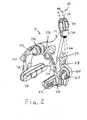
- is a rear perspective view of the bicycle brake;
- FIG. 3
- is a rear exploded view of the bicycle brake;
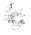
- FIG. 4
- is a front view of the bicycle brake in a non-actuated, non-braking position; and
- FIG. 5
- is a front view of the bicycle brake in an actuated braking position.
- Some embodiments of the invention will now be explained with reference to the drawing figures. Referring to
FIGS. 1-3 , abicycle brake 10 is shown. Thebicycle brake 10 includes a firstmain brake arm 12 and a secondmain brake arm 14. The bicycle brake also includes a firsttransfer brake arm 16 and a secondtransfer brake arm 18. The firstmain brake arm 12 has afirst mounting bore 20 and the secondmain brake arm 14 has asecond mounting bore 22 which permit the brake arms to be mounted to the frame of a bicycle. In this embodiment, a single fastener or mountingbolt 24 passes through thebores bias spring 26 is attached to agrommet 28 which themounting bolt 24 also passes through. Themounting bolt 24 supports thebias spring 26 so that its respective ends contact aspring mounting boss 30 on the firstmain brake arm 12 and aspring mounting boss 32 on the secondmain brake arm 14. Thebias spring 26 therefore biases the first and secondmain brake arms respective brake pads main brake arm 12 has acable guide 34 which receives acontrol cable 35, in this embodiment a Bowden-type cable. Thecontrol cable 35 includes acable housing 38 and abrake cable 66 slidably disposed in thecable housing 38. Thecable guide 34 includes a seat that retains thecable housing 38 and allows thebrake cable 66 to extend through thecable guide 34. Thecable guide 34 includes abarrel adjuster 36 for adjusting the length of thebrake cable 66. - The first
transfer brake arm 16 is pivotally connected to the firstmain brake arm 12 by afirst pivot pin 40 extending through abore 42 in the firstmain brake arm 12 and abore 44 in the firsttransfer brake arm 16. The secondtransfer brake arm 18 is connected to the secondmain brake arm 14 by asecond pivot pin 46 extending through a bore 48 in the secondmain brake arm 14 and a bore 50 in the secondmain brake arm 14. A secondtransfer brake arm 18 is connected to the firsttransfer brake arm 16 by athird pivot pin 54 which extends through abore 56 in the secondtransfer brake arm 18 and abore 58 in the firsttransfer brake arm 16. The firsttransfer brake arm 16 therefore is pivotally connected to both the firstmain brake arm 12 and to the secondtransfer brake arm 18. - The first
transfer brake arm 16 has, at its projecting end, a cable engaging feature that engages thebrake cable 66 so that brake cable force is transferred to the firsttransfer brake arm 16. In this embodiment, the firsttransfer brake arm 16 has anaperture 60 therethrough. Theaperture 60 serves as a female cable bore that receives acable anchor 62. Thecable anchor 62 is a clamp that retains an end portion of thebrake cable 66. Thecable anchor 62 may be of a quick release type that can quickly latch on to or release thecable 66. Alternatively, the firsttransfer brake arm 16 has thecable guide 34 and the firstmain brake arm 12 has thecable anchor 62. - The first
main brake arm 12 terminates in alower extension 70 which supports abrake pad 72. The secondmain brake arm 14 terminates in alower extension 74 which supports abrake pad 76. - Referring now particularly to
FIGS. 4 and5 , movement of thebicycle brake 10 between a non-actuated rest position, shown inFIG. 4 , and an actuated, braking position shown inFIG. 5 , will be described.FIGS. 4 and5 also schematically depict awheel rim 99. - The brake actuation sequence is initiated by pulling on or tensioning the
brake cable 66 by means of a purposed cable pulling mechanism, such as a brake lever. During actuation, thebrake cable housing 38 is retained relative to thecable guide 34. Thecable 66 is thus drawn upward applying the upward tensile force at the female cable bore 60. As thecable 66 is tensioned upward at the female cable bore 60, the firsttransfer brake arm 16 rotates clockwise aboutfirst pivot pin 40, as well as clockwise about an instant center that can be approximated by the location of thethird pivot pin 54. Thefirst pivot pin 40 allows the transfer force to the firstmain brake arm 12, displacing the firstmain brake arm 12 counterclockwise about themounting bolt 24. This causes thebrake pad 72 to move towards thewheel rim 99 supplying thewheel rim 99 with a mechanically advantageous braking force. Simultaneously, the firsttransfer brake arm 16 transfers a compressive force to the secondtransfer brake arm 18 driving it upwards, by means of the pivotal connection at thethird pivot pin 54. This transfers force to the secondmain brake arm 14, by means of thesecond pivot pin 46, allowing the secondmain brake arm 14 to rotate clockwise about the mountingbolt 24, causing thebrake pad 76 to move towards thewheel rim 99, supplying thewheel rim 99 with a mechanically advantageous braking force. When the brake lever is released, the brake tension in thecable 66 is relaxed, and thebias spring 26 biases themain brake arms respective brake pads - Each of the first and second
main brake arms transfer brake arms
Claims (15)
- A bicycle brake (10) actuated by a control cable (35), the bicycle brake comprising:a first main brake arm (12) having a cable guide (34) for receiving the control cable (35);a second main brake arm (14) mounted for pivotable movement with respect to the first main brake arm (12);a first transfer brake arm (16) pivotally connected to the first main brake arm (12), the first transfer brake arm (16) having a cable anchor (62) for receiving the control cable (35), the control cable (35) extending between the cable guide (34) and the cable anchor (62); anda second transfer brake arm (18) pivotally connected to the first transfer brake arm (16), and pivotally connected to the second main brake arm (14).
- The bicycle brake (10) according to claim 1, wherein the cable anchor (62) releasably retains the control cable (35).
- The bicycle brake (10) according to claim 1 or 2, wherein the pivotal connection between the second transfer brake arm (18) and the first transfer brake arm (16) is disposed on the first transfer brake arm (16) between (i) the pivotal connection of the first transfer brake arm (16) to the first main brake arm (12) and (ii) the cable anchor (62).
- The bicycle brake (10) according to one of the preceding claims, wherein the second transfer brake arm (16) includes an elongated link.
- The bicycle brake (10) according to one of the preceding claims, wherein the control cable (35) includes a cable housing (38) and a brake cable (66) slidably disposed within the cable housing (38), the cable guide (34) retaining the cable housing (38) and allowing the brake cable (66) to extend through the cable guide (34) to the cable anchor (62), the cable anchor (62) retaining an end portion of the brake cable (66).
- The bicycle brake (10) according to one of the preceding claims, wherein the pivotal connection between the second transfer brake arm (18) and the first transfer brake arm (16) is disposed on the first transfer brake arm (16) between (i) the pivotal connection of the first transfer brake arm (16) to the first main brake arm (12) and (ii) the cable anchor (62).
- The bicycle brake (10) according to one of the preceding claims, wherein the first main brake arm (12) has a first end that supports a first brake shoe, and wherein the second main brake arm (14) has a second end that supports a second brake shoe.
- The bicycle brake according to claim 7, wherein the first and second main brake arms (12, 14) including first and second mounting bores (20, 22), respectively, for mounting the bicycle brake to a bicycle frame, and wherein the second mounting bore (22) is disposed between (i) the second end of the second main brake arm (14) and (ii) the pivotal connection of the second transfer brake arm (18) to the second main brake arm (14).
- The bicycle brake (10) according to claim 8, further comprising a fastener (24) passing through the first mounting bore (20) and the second mounting bore (12) to fasten the bicycle brake (10) to the bicycle frame.
main brake arm has a second end that supports a second brake shoe. - The bicycle brake (10) according to one of claims 7 to 9, further comprising a spring (26) that biases the first end of the first main brake arm (12) away from the second end of the second main brake arm (14).
- The bicycle brake (10) according to one of the preceding claims, further comprising:a first pin (40) that pivotally connects the first transfer brake arm (16) to the first main brake arm (12);a second pin (46) that pivotally connects the second transfer brake arm (18) to the first transfer brake arm (16); anda third pin (54) that pivotally connects the second transfer brake arm (18) to the second main brake arm (14).
- The bicycle brake (10) according to claim 13, wherein
the first pin (40) passes through a first bore in the first transfer brake arm (16) and a second bore in the first main brake arm (12);
the second pin (46) passes through a third bore in the second transfer brake arm (18) and a fourth bore in the first transfer brake arm (16); and
the third pin (54) passes through a fifth bore in the second transfer brake arm (18) and a sixth bore in the second main brake arm (14). - The bicycle brake (10) according to claim 13, wherein the first pin (40), the second pin (46), and the third pin (54) are substantially parallel to each other.
- The bicycle brake (10) according to one of the preceding claims,
wherein the cable anchor (62) releasably retains the brake cable (35). - The bicycle brake (10) according to one of the preceding claims,
wherein the pivotal connection between the second transfer brake arm (18) and the first transfer brake arm (16) is disposed on the first transfer brake arm (16) between (i) the pivotal connection of the first transfer brake arm to the first main brake arm and (ii) the cable anchor.
Applications Claiming Priority (1)
| Application Number | Priority Date | Filing Date | Title |
|---|---|---|---|
| US13/006,183 US8485320B2 (en) | 2011-01-13 | 2011-01-13 | Bicycle brake |
Publications (2)
| Publication Number | Publication Date |
|---|---|
| EP2476609A2 true EP2476609A2 (en) | 2012-07-18 |
| EP2476609A3 EP2476609A3 (en) | 2013-11-13 |
Family
ID=45464199
Family Applications (1)
| Application Number | Title | Priority Date | Filing Date |
|---|---|---|---|
| EP11010047.6A Withdrawn EP2476609A3 (en) | 2011-01-13 | 2011-12-21 | Bicycle brake |
Country Status (5)
| Country | Link |
|---|---|
| US (1) | US8485320B2 (en) |
| EP (1) | EP2476609A3 (en) |
| CN (1) | CN102582442A (en) |
| DE (1) | DE102012000244A1 (en) |
| TW (1) | TWI482720B (en) |
Families Citing this family (9)
| Publication number | Priority date | Publication date | Assignee | Title |
|---|---|---|---|---|
| US20140190775A1 (en) * | 2013-01-10 | 2014-07-10 | Felt Racing, Llc | Brake having custom kinematics and wide range adjustability for wide and narrow rims |
| US9145186B2 (en) * | 2014-04-29 | 2015-09-29 | Tektro Technology Corporation | Quick-release device of bicycle brake cable |
| TWI537172B (en) * | 2015-03-24 | 2016-06-11 | 溫芫鋐 | Brake for a bicycle |
| US10189537B2 (en) | 2015-03-24 | 2019-01-29 | Yuan-Hung WEN | Brake for bicycle |
| JP6826826B2 (en) * | 2015-06-30 | 2021-02-10 | カンパニョーロ・ソシエタ・ア・レスポンサビリタ・リミタータCampagnolo Societa A Responsabilita Limitata | Bicycle brake |
| US9821880B2 (en) * | 2015-08-07 | 2017-11-21 | Shimano Inc. | Bicycle rim brake |
| NL2017387B1 (en) * | 2016-08-30 | 2018-03-08 | Just Ride B V | Bicycle brake with lever system, comprising an adjustment member |
| US11377168B2 (en) | 2018-08-01 | 2022-07-05 | Pacific Cycle, Llc | Brake caliper |
| USD908564S1 (en) | 2019-07-29 | 2021-01-26 | Pacific Cycle, Llc | Brake caliper lever assembly |
Family Cites Families (13)
| Publication number | Priority date | Publication date | Assignee | Title |
|---|---|---|---|---|
| GB433377A (en) * | 1934-02-14 | 1935-08-14 | J A Phillips & Co Ltd | Improvements in and relating to brakes for cycles, motor cycles and the like |
| FR1013460A (en) * | 1950-03-03 | 1952-07-29 | Brake shoe control method for cycles and others | |
| US3628635A (en) | 1969-05-10 | 1971-12-21 | Kiyokazu Yoshigai | Bicycle brake |
| US4290507A (en) * | 1978-02-15 | 1981-09-22 | Brown Lawrence G | Actuating system and apparatus for brakes and clutches and the like |
| JPH0314462Y2 (en) * | 1985-12-19 | 1991-03-29 | ||
| DE4025708A1 (en) * | 1990-08-14 | 1992-02-20 | Fichtel & Sachs Ag | ARRANGEMENT OF LOCKING CLIPS IN BICYCLE HUBS |
| CN1081567C (en) * | 1993-07-11 | 2002-03-27 | 李雄飞 | Strong wire-controlled brake |
| JP3279169B2 (en) * | 1996-04-02 | 2002-04-30 | 株式会社シマノ | Shoe holder |
| US7000739B2 (en) | 2002-10-07 | 2006-02-21 | Ciamillo Theodore J | Cam assisted wheel brake |
| US7422090B1 (en) | 2007-07-24 | 2008-09-09 | Adam Preuss | Caliper brake assembly |
| US7975810B2 (en) | 2007-08-10 | 2011-07-12 | Liu Robert Z | Cam activated bicycle wheel brake |
| TW201034902A (en) * | 2009-03-16 | 2010-10-01 | R Ginster Nicholas | Structure of link lever for bicycle brake |
| TWM384824U (en) * | 2010-02-11 | 2010-07-21 | Sheng-Yao Yang | Cellular type brake clip device |
-
2011
- 2011-01-13 US US13/006,183 patent/US8485320B2/en not_active Expired - Fee Related
- 2011-12-20 TW TW100147465A patent/TWI482720B/en active
- 2011-12-21 EP EP11010047.6A patent/EP2476609A3/en not_active Withdrawn
-
2012
- 2012-01-09 DE DE102012000244A patent/DE102012000244A1/en active Pending
- 2012-01-12 CN CN2012100091001A patent/CN102582442A/en active Pending
Non-Patent Citations (1)
| Title |
|---|
| None |
Also Published As
| Publication number | Publication date |
|---|---|
| CN102582442A (en) | 2012-07-18 |
| EP2476609A3 (en) | 2013-11-13 |
| DE102012000244A1 (en) | 2012-07-19 |
| US20120181120A1 (en) | 2012-07-19 |
| US8485320B2 (en) | 2013-07-16 |
| TW201233581A (en) | 2012-08-16 |
| TWI482720B (en) | 2015-05-01 |
Similar Documents
| Publication | Publication Date | Title |
|---|---|---|
| US8485320B2 (en) | Bicycle brake | |
| US8505694B2 (en) | Link unit of brake assembly for bicycles | |
| US9567032B2 (en) | Brake caliper arrangement structure for motorcycle | |
| US8413769B2 (en) | Bicycle brake system using cam mechanism | |
| US10183724B2 (en) | Bicycle hydraulic operating system | |
| US9233731B1 (en) | Bicycle rim brake | |
| CN110023184B (en) | Synchronous braking system | |
| EP3069981B1 (en) | Motorcycle | |
| US20080202866A1 (en) | Bicycle brake | |
| US7464798B2 (en) | Hydraulic bicycle brake mechanism | |
| CN102398663A (en) | Brake structure for controlling front and rear wheel brakes | |
| US8056682B2 (en) | Bicycle brake device | |
| US7422090B1 (en) | Caliper brake assembly | |
| US20190315286A1 (en) | Bike retaining device | |
| WO2016108247A1 (en) | Synchronized braking system | |
| EP2444310A1 (en) | Bicycle brake system using cam mechanism | |
| US6607056B2 (en) | Brake apparatus for a bicycle and bicycle comprising this apparatus | |
| JP2006111030A (en) | Brake device for handlebar vehicle | |
| KR101217587B1 (en) | Parking brake tension controller | |
| WO2011037669A1 (en) | Brake system and method and two-wheeled vehicle using the same | |
| JP2004042908A (en) | Brake device for bar handle vehicle | |
| US20130199877A1 (en) | Cantilever brake with quick release mechanism | |
| JPH0516863A (en) | Brake control for bicycle | |
| JPH0322355B2 (en) | ||
| US20070137948A1 (en) | Bicycle brake mechanism |
Legal Events
| Date | Code | Title | Description |
|---|---|---|---|
| PUAI | Public reference made under article 153(3) epc to a published international application that has entered the european phase |
Free format text: ORIGINAL CODE: 0009012 |
|
| AK | Designated contracting states |
Kind code of ref document: A2 Designated state(s): AL AT BE BG CH CY CZ DE DK EE ES FI FR GB GR HR HU IE IS IT LI LT LU LV MC MK MT NL NO PL PT RO RS SE SI SK SM TR |
|
| AX | Request for extension of the european patent |
Extension state: BA ME |
|
| PUAL | Search report despatched |
Free format text: ORIGINAL CODE: 0009013 |
|
| AK | Designated contracting states |
Kind code of ref document: A3 Designated state(s): AL AT BE BG CH CY CZ DE DK EE ES FI FR GB GR HR HU IE IS IT LI LT LU LV MC MK MT NL NO PL PT RO RS SE SI SK SM TR |
|
| AX | Request for extension of the european patent |
Extension state: BA ME |
|
| RIC1 | Information provided on ipc code assigned before grant |
Ipc: B62L 1/12 20060101AFI20131004BHEP |
|
| 17P | Request for examination filed |
Effective date: 20140506 |
|
| RBV | Designated contracting states (corrected) |
Designated state(s): AL AT BE BG CH CY CZ DE DK EE ES FI FR GB GR HR HU IE IS IT LI LT LU LV MC MK MT NL NO PL PT RO RS SE SI SK SM TR |
|
| 17Q | First examination report despatched |
Effective date: 20141126 |
|
| STAA | Information on the status of an ep patent application or granted ep patent |
Free format text: STATUS: THE APPLICATION IS DEEMED TO BE WITHDRAWN |
|
| 18D | Application deemed to be withdrawn |
Effective date: 20150408 |