EP2476507B1 - Lotlegierung und Verfahren zur Reparatur eines Bauteils - Google Patents
Lotlegierung und Verfahren zur Reparatur eines Bauteils Download PDFInfo
- Publication number
- EP2476507B1 EP2476507B1 EP12002269.4A EP12002269A EP2476507B1 EP 2476507 B1 EP2476507 B1 EP 2476507B1 EP 12002269 A EP12002269 A EP 12002269A EP 2476507 B1 EP2476507 B1 EP 2476507B1
- Authority
- EP
- European Patent Office
- Prior art keywords
- solder alloy
- solder
- melting point
- alloy according
- scandium
- Prior art date
- Legal status (The legal status is an assumption and is not a legal conclusion. Google has not performed a legal analysis and makes no representation as to the accuracy of the status listed.)
- Not-in-force
Links
Images

Classifications
-
- C—CHEMISTRY; METALLURGY
- C22—METALLURGY; FERROUS OR NON-FERROUS ALLOYS; TREATMENT OF ALLOYS OR NON-FERROUS METALS
- C22C—ALLOYS
- C22C19/00—Alloys based on nickel or cobalt
- C22C19/03—Alloys based on nickel or cobalt based on nickel
- C22C19/05—Alloys based on nickel or cobalt based on nickel with chromium
- C22C19/051—Alloys based on nickel or cobalt based on nickel with chromium and Mo or W
- C22C19/057—Alloys based on nickel or cobalt based on nickel with chromium and Mo or W with the maximum Cr content being less 10%
-
- B—PERFORMING OPERATIONS; TRANSPORTING
- B23—MACHINE TOOLS; METAL-WORKING NOT OTHERWISE PROVIDED FOR
- B23K—SOLDERING OR UNSOLDERING; WELDING; CLADDING OR PLATING BY SOLDERING OR WELDING; CUTTING BY APPLYING HEAT LOCALLY, e.g. FLAME CUTTING; WORKING BY LASER BEAM
- B23K1/00—Soldering, e.g. brazing, or unsoldering
- B23K1/0008—Soldering, e.g. brazing, or unsoldering specially adapted for particular articles or work
- B23K1/0018—Brazing of turbine parts
-
- B—PERFORMING OPERATIONS; TRANSPORTING
- B23—MACHINE TOOLS; METAL-WORKING NOT OTHERWISE PROVIDED FOR
- B23K—SOLDERING OR UNSOLDERING; WELDING; CLADDING OR PLATING BY SOLDERING OR WELDING; CUTTING BY APPLYING HEAT LOCALLY, e.g. FLAME CUTTING; WORKING BY LASER BEAM
- B23K35/00—Rods, electrodes, materials, or media, for use in soldering, welding, or cutting
- B23K35/22—Rods, electrodes, materials, or media, for use in soldering, welding, or cutting characterised by the composition or nature of the material
- B23K35/24—Selection of soldering or welding materials proper
- B23K35/30—Selection of soldering or welding materials proper with the principal constituent melting at less than 1550 degrees C
- B23K35/3033—Ni as the principal constituent
- B23K35/304—Ni as the principal constituent with Cr as the next major constituent
-
- C—CHEMISTRY; METALLURGY
- C22—METALLURGY; FERROUS OR NON-FERROUS ALLOYS; TREATMENT OF ALLOYS OR NON-FERROUS METALS
- C22F—CHANGING THE PHYSICAL STRUCTURE OF NON-FERROUS METALS AND NON-FERROUS ALLOYS
- C22F1/00—Changing the physical structure of non-ferrous metals or alloys by heat treatment or by hot or cold working
- C22F1/10—Changing the physical structure of non-ferrous metals or alloys by heat treatment or by hot or cold working of nickel or cobalt or alloys based thereon
-
- F—MECHANICAL ENGINEERING; LIGHTING; HEATING; WEAPONS; BLASTING
- F05—INDEXING SCHEMES RELATING TO ENGINES OR PUMPS IN VARIOUS SUBCLASSES OF CLASSES F01-F04
- F05B—INDEXING SCHEME RELATING TO WIND, SPRING, WEIGHT, INERTIA OR LIKE MOTORS, TO MACHINES OR ENGINES FOR LIQUIDS COVERED BY SUBCLASSES F03B, F03D AND F03G
- F05B2230/00—Manufacture
- F05B2230/20—Manufacture essentially without removing material
- F05B2230/23—Manufacture essentially without removing material by permanently joining parts together
- F05B2230/232—Manufacture essentially without removing material by permanently joining parts together by welding
- F05B2230/238—Soldering
-
- F—MECHANICAL ENGINEERING; LIGHTING; HEATING; WEAPONS; BLASTING
- F05—INDEXING SCHEMES RELATING TO ENGINES OR PUMPS IN VARIOUS SUBCLASSES OF CLASSES F01-F04
- F05B—INDEXING SCHEME RELATING TO WIND, SPRING, WEIGHT, INERTIA OR LIKE MOTORS, TO MACHINES OR ENGINES FOR LIQUIDS COVERED BY SUBCLASSES F03B, F03D AND F03G
- F05B2230/00—Manufacture
- F05B2230/80—Repairing, retrofitting or upgrading methods
-
- F—MECHANICAL ENGINEERING; LIGHTING; HEATING; WEAPONS; BLASTING
- F05—INDEXING SCHEMES RELATING TO ENGINES OR PUMPS IN VARIOUS SUBCLASSES OF CLASSES F01-F04
- F05C—INDEXING SCHEME RELATING TO MATERIALS, MATERIAL PROPERTIES OR MATERIAL CHARACTERISTICS FOR MACHINES, ENGINES OR PUMPS OTHER THAN NON-POSITIVE-DISPLACEMENT MACHINES OR ENGINES
- F05C2201/00—Metals
- F05C2201/04—Heavy metals
- F05C2201/0403—Refractory metals, e.g. V, W
- F05C2201/0406—Chromium
-
- F—MECHANICAL ENGINEERING; LIGHTING; HEATING; WEAPONS; BLASTING
- F05—INDEXING SCHEMES RELATING TO ENGINES OR PUMPS IN VARIOUS SUBCLASSES OF CLASSES F01-F04
- F05C—INDEXING SCHEME RELATING TO MATERIALS, MATERIAL PROPERTIES OR MATERIAL CHARACTERISTICS FOR MACHINES, ENGINES OR PUMPS OTHER THAN NON-POSITIVE-DISPLACEMENT MACHINES OR ENGINES
- F05C2201/00—Metals
- F05C2201/04—Heavy metals
- F05C2201/0433—Iron group; Ferrous alloys, e.g. steel
- F05C2201/0463—Cobalt
-
- F—MECHANICAL ENGINEERING; LIGHTING; HEATING; WEAPONS; BLASTING
- F05—INDEXING SCHEMES RELATING TO ENGINES OR PUMPS IN VARIOUS SUBCLASSES OF CLASSES F01-F04
- F05C—INDEXING SCHEME RELATING TO MATERIALS, MATERIAL PROPERTIES OR MATERIAL CHARACTERISTICS FOR MACHINES, ENGINES OR PUMPS OTHER THAN NON-POSITIVE-DISPLACEMENT MACHINES OR ENGINES
- F05C2201/00—Metals
- F05C2201/04—Heavy metals
- F05C2201/0433—Iron group; Ferrous alloys, e.g. steel
- F05C2201/0466—Nickel
Definitions
- the invention relates to a solder alloy according to claim 1 and a method for repairing a component according to claim 14.
- Components sometimes need to be repaired after manufacture, for example after casting or after they have been used and cracked.
- soldering process works with respect to the temperature during the welding process and thus with respect to the melting temperature of the substrate material at lower temperatures. Nevertheless, the solder should have a high strength so that the solder-filled crack or the depression at high operating temperatures does not lead to a weakening of the entire component at the high operating temperatures.
- the EP 1 293 286 A2 discloses various solder alloys containing zirconium but also boron.
- the US 6,190,467 B1 discloses solder nickel-based solder alloys containing boron and silicon.
- the object is achieved by a solder made of a solder alloy according to claim 1 and a method according to claim 14.
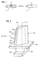
- FIG. 1 shows a component 1, which is treated with a solder 10 of a solder alloy according to the invention.
- the component 1 comprises a substrate 4 which, in particular for components for high-temperature applications, in particular for turbine blades 120, 130 (FIG. Fig. 2 ) or combustion chamber elements 155 (FIG. Fig. 3 ) for steam or gas turbines 100 ( Fig. 4 ) consists of an iron-, nickel- or cobalt-based superalloy. These may preferably be the known materials PWA 1483, PWA 1484 or Rene N5.
- Lot 10 is also used for blades for aircraft.
- the substrate 4 has a crack 7 or a recess 7, which is to be filled by soldering.
- the cracks 7 or recesses 7 are preferably about 200 microns wide and can be up to 5mm deep.
- the solder 10 is applied from the solder alloy in or in the vicinity of the recess 7 and by a heat treatment (+ T), the solder 10 melts below a Melting temperature of the substrate 4 and fills the recess 7 completely.
- the solder alloy is nickel-based and has the further components chromium, cobalt and tungsten and 2wt% to 22.4wt% of a melting point depressant containing at least one element from the group scandium (Sc), aluminum (A1), titanium (Ti), zirconium ( Zr) or tantalum (Ta).
- a melting point depressant containing at least one element from the group scandium (Sc), aluminum (A1), titanium (Ti), zirconium ( Zr) or tantalum (Ta).
- the proportions of chromium are preferably 7.5% to 11% by weight and more preferably 10% by weight.
- the proportions of cobalt are preferably between 8% and 11.4wt% and more preferably 10.4wt%.
- the proportions of tungsten are preferably from 2.8wt% to 6.9wt%, and more preferably 3.8wt% or 5.9wt%.
- molybdenum Mo
- Other elements may be present, preferably the above listing is final of nickel, chromium, cobalt, tungsten, the melting point depressant and optionally molybdenum.
- the solder preferably contains no boron, no silicon or no hafnium.
- rhenium can preferably be dispensed with.
- the solder 10 can be connected to the substrate 4 of the component 1, 120, 130, 155 in an isothermal or a temperature gradient method.
- a gradient method is suitable if the substrate 4 has a directional structure, for example an SX or DS structure, so that the solder 10 subsequently has a directed structure.
- the component 1 does not need to have a directionally solidified structure (but a CC structure), whereby a high strength of the component 1 is achieved at high temperatures by the directionally solidified structure in the repaired site 3, because the directionally solidified structure of the solder 7 in FIG repaired spot the negative effect of low melting point on the mechanical strength at high temperatures.
- an inert gas particularly argon, which reduces the chromium evaporation from the substrate 4 at the high temperatures, or uses a reducing gas (argon / hydrogen).
- the solder 10 can also be applied over a large area to a surface of a component 1, 120, 130, 155 in order to achieve a thickening of the substrate 4, in particular in the case of hollow components.
- the solder 10 is used to fill in cracks 7 or depressions 7.
- the table shows exemplary compositions HT according to the invention of the solder alloy of the solder 10 (in wt%), the remainder being nickel.
- alloy Cr Co Not a word W Ta al Ti Zr sc HT6 10 9 0 3.8 0 0 0 0 8th HT7 10 9 0 3.8 3 0 0 0 10 HT8 10 9 0 3.8 0 0 0 6 HT12 8.5 10.4 0 4.4 0 0 0 13.4 0.5 HT13 10 9 0 3.8 0 0 0 10 HT18 10 9 1.9 3.8 0 3 3 0 0.5 HT22 10 9 0 3.8 0 3 0 0 6 HT23 10 9 1.9 5.9 0 0 0 0 2 HT24 10 9 1.9 3.8 0 0 0 13.4 2 HT25 10 9 1.9 3.8 0 0 0 13.4 4
- the solder alloys can preferably be divided into at least four segments with respect to the composition of the melting point depressant consisting of Zr, Al, Ti, Ta and Sc: the first segment contains at least zirconium, the second has at least scandium and a third segment comprises zirconium, aluminum, titanium , Tantalum with small amounts of scandium (up to 2 wt%).
- the first segment consists either only of zirconium (claims 1 + 2) or only of zirconium, aluminum, titanium and tantalum (Claims 1 + 4) or only zirconium and two other elements from the group aluminum, titanium, tantalum (claims 1 + 5) or only zirconium with an element selected from aluminum, titanium, tantalum (claims 1 + 6).
- titanium, aluminum and / or zirconium are particularly advantageous as these elements promote the formation of the y 'phase in a nickel-based material which improves the high temperature mechanical properties.
- One, two or three of these three elements can advantageously be used in the solder 10 (see HT5, HT9, HT10, HT14, HT19).
- the second segment consists either only of scandium (claims 1 + 7) or only of scandium, aluminum, titanium and tantalum (claims 1 + 8 + 12 + 13) or only of scandium and two elements of the group aluminum, titanium or tantalum (claims 1 + 8 + 12 + 14) or only from scandium and an element of the group aluminum, titanium, tantalum (claims 1 + 8 + 12 + 15).
- the third segment consists of zirconium, small proportions (up to 2wt%) of scandium and up to three elements from the group aluminum, titanium and tantalum: Zr + Sc + 3 from (Al, Ti, Ta): Claims 1 + 3 + 13 + 25; Zr + Sc + 2 from (Al, Ti, Ta): Claims 1 + 3 + 14 + 25; Zr + Sc + 1 of (Al, Ti, Ta): Claims 1 + 3 + 15 + 25.
- a preferred solder alloy may not have chromium.
- preferred values for chromium may range from 4.0wt% to less than 7.5wt%.
- Another preferred range is a proportion of greater than 11wt% to greater than 12wt% chromium.
- no cobalt is used for the solder alloy.
- Another advantageous value range for cobalt is in the range of 4wt% to less than 8wt%.
- solder alloy may preferably contain no tungsten.
- Preferred values for tungsten are also values between 1.8wt% and less than 2.8wt%.
- rhenium (Re) is also added to the brazing alloy, particularly in a range of from 2.5wt% to 3wt%.
- At least one, in particular a rare earth element, in particular yttrium (Y) is also added, and preferably in a value range of 0.5% by weight to 2% by weight.
- Y yttrium
- hafnium is added, especially in a range of 0.5wt% to 2.5wt%.
- FIG. 2 3 shows a perspective view of a moving blade 120 or guide blade 130 of a turbomachine 100 (FIG. Fig. 4 ) extending along a longitudinal axis 121.
- the turbomachine may be a gas turbine of an aircraft or a power plant for power generation, a steam turbine or a compressor.
- the blade 120, 130 has along the longitudinal axis 121 consecutively a fastening region 400, a blade platform 403 adjoining thereto and an airfoil 406.
- the blade 130 may have at its blade tip 415 another platform (not shown).
- a blade root 183 is formed, which serves for attachment of the blades 120, 130 to a shaft or a disc (not shown).
- the blade root 183 is designed, for example, as a hammer head. Other designs as Christmas tree or Schwalbenschwanzfuß are possible.
- the blade 120, 130 has a leading edge 409 and a trailing edge 412 for a medium flowing past the airfoil 406.
- Such superalloys are for example from EP 1 204 776 B1 .
- EP 1 306 454 .
- the blade 120, 130 can be made by a casting process, also by directional solidification, by a forging process, by a milling process or combinations thereof.
- Workpieces with a monocrystalline structure or structures are used as components for machines which are exposed to high mechanical, thermal and / or chemical stresses during operation.
- dendritic crystals are aligned along the heat flow and form either a columnar grain structure (columnar, i.e., grains that run the full length of the workpiece and here, in common usage, are referred to as directionally solidified) or a monocrystalline structure, i. the whole workpiece consists of a single crystal.
- a columnar grain structure columnar, i.e., grains that run the full length of the workpiece and here, in common usage, are referred to as directionally solidified
- a monocrystalline structure i. the whole workpiece consists of a single crystal.
- directionally solidified microstructures which means both single crystals that have no grain boundaries or at most small angle grain boundaries, and stem crystal structures that have probably longitudinal grain boundaries but no transverse grain boundaries. These second-mentioned crystalline structures are also known as directionally solidified structures.
- the blades 120, 130 may have coatings against corrosion or oxidation, e.g. M is at least one element of the group iron (Fe), cobalt (Co), nickel (Ni), X is an active element and stands for yttrium (Y) and / or silicon and / or at least one element of the rare ones Earth, or hafnium (Hf)).
- M is at least one element of the group iron (Fe), cobalt (Co), nickel (Ni)
- X is an active element and stands for yttrium (Y) and / or silicon and / or at least one element of the rare ones Earth, or hafnium (Hf)).
- Such alloys are known from the EP 0 486 489 B1 .
- EP 0 412 397 B1 or EP 1 306 454 A1 are known from the EP 0 486 489 B1 .
- thermal barrier coating may be present and consists for example of ZrO 2 , Y 2 O 4 -ZrO 3 , ie it is not, partially or completely stabilized by yttrium oxide and / or calcium oxide and / or magnesium oxide.
- Electron beam evaporation produces stalk-shaped grains in the thermal barrier coating.
- Refurbishment means that components 120, 130 may need to be deprotected after use (e.g., by sandblasting). This is followed by removal of the corrosion and / or oxidation layers or products. Optionally, cracks in the component 120, 130 are repaired with the solder 10 according to the invention. This is followed by a re-coating of the component 120, 130 and a renewed use of the component 120, 130.
- the blade 120, 130 may be hollow or solid. If the blade 120, 130 is to be cooled, it is hollow and may still film cooling holes 418 (indicated by dashed lines) on.
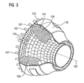
- the combustor 110 is configured as a so-called annular combustor wherein a plurality of burners 107 circumferentially disposed about an axis of rotation 102 open into a common combustor space 154 that creates flames 156.
- the combustion chamber 110 is configured in its entirety as an annular structure, which is positioned around the axis of rotation 102 around.
- the combustion chamber 110 is designed for a comparatively high temperature of the working medium M of about 1000 ° C to 1600 ° C.
- the combustion chamber wall 153 is on their the working medium M facing side provided with an inner lining formed of heat shield elements 155.
- Each heat shield element 155 made of an alloy is equipped on the working medium side with a particularly heat-resistant protective layer (MCrAlX layer and / or ceramic coating) or is made of high-temperature-resistant material (solid ceramic blocks).
- M is at least one element of the group iron (Fe), cobalt (Co), nickel (Ni), X is an active element and stands for yttrium (Y) and / or silicon and / or at least one element of the rare earths, or hafnium (Hf).
- MCrAlX means: M is at least one element of the group iron (Fe), cobalt (Co), nickel (Ni), X is an active element and stands for yttrium (Y) and / or silicon and / or at least one element of the rare earths, or hafnium (Hf).
- Such alloys are known from the EP 0 486 489 B1 .
- EP 0 412 397 B1 or EP 1 306 454 A1 are known from the EP 0 486 489 B1 .
- EP 0 412 397 B1 or EP 1 306 454 A1 is known from the EP 0 486 489 B1 .
- MCrAlX may still be present, for example, a ceramic thermal barrier coating and consists for example of ZrO 2 , Y 2 O 4 -ZrO 2 , ie it is not, partially or completely stabilized by yttria and / or calcium oxide and / or magnesium oxide.
- Electron beam evaporation produces stalk-shaped grains in the thermal barrier coating.
- Refurbishment means that heat shield elements 155 may need to be deprotected (e.g., by sandblasting) after use. This is followed by removal of the corrosion and / or oxidation layers or products. Optionally, cracks are also repaired with the solder 10 according to the invention in the heat shield element 155. This is followed by a recoating of the heat shield elements 155 and a renewed use of the heat shield elements 155.
- the heat shield elements 155 are then, for example, hollow and possibly still have film cooling holes (not shown) which open into the combustion chamber space 154.
- FIG. 4 shows by way of example a gas turbine 100 in a longitudinal partial section.
- the gas turbine 100 has inside a rotatably mounted about a rotation axis 102 rotor 103 with a shaft 101, which is also referred to as a turbine runner.
- an intake housing 104 a compressor 105, for example, a toroidal combustion chamber 110, in particular annular combustion chamber, with a plurality of coaxially arranged burners 107, a turbine 108 and the exhaust housing 109th
- a compressor 105 for example, a toroidal combustion chamber 110, in particular annular combustion chamber, with a plurality of coaxially arranged burners 107, a turbine 108 and the exhaust housing 109th
- the annular combustion chamber 110 communicates with an annular annular hot gas channel 111, for example.
- annular annular hot gas channel 111 for example.
- turbine stages 112 connected in series form the turbine 108.
- Each turbine stage 112 is formed, for example, from two blade rings. As seen in the direction of flow of a working medium 113, in the hot gas channel 111 of a row of guide vanes 115, a series 125 formed of rotor blades 120 follows.
- the guide vanes 130 are fastened to an inner housing 138 of a stator 143, whereas the moving blades 120 of a row 125 are attached to the rotor 103 by means of a turbine disk 133, for example.
- air 105 is sucked in and compressed by the compressor 105 through the intake housing 104.
- the compressed air provided at the turbine-side end of the compressor 105 is supplied to the burners 107 where it is mixed with a fuel.
- the mixture is then formed to form the working medium 113 in the combustion chamber 110 burned. From there, the working medium 113 flows along the hot gas channel 111 past the guide vanes 130 and the rotor blades 120. On the rotor blades 120, the working medium 113 expands in a pulse-transmitting manner, so that the rotor blades 120 drive the rotor 103 and drive the machine coupled to it.
- the components exposed to the hot working medium 113 are subject to thermal loads during operation of the gas turbine 100.
- the guide vanes 130 and rotor blades 120 of the first turbine stage 112, viewed in the flow direction of the working medium 113, are subjected to the greatest thermal stress in addition to the heat shield elements lining the annular combustion chamber 110.
- substrates of the components may have a directional structure, i. they are monocrystalline (SX structure) or have only longitudinal grains (DS structure).
- iron-, nickel- or cobalt-based superalloys are used as the material for the components.
- Such superalloys are for example from EP 1 204 776 B1 .
- the vane 130 has a guide vane foot (not shown here) facing the inner housing 138 of the turbine 108 and a vane head opposite the vane foot.
- the vane head faces the rotor 103 and fixed to a mounting ring 140 of the stator 143.
Landscapes
- Engineering & Computer Science (AREA)
- Mechanical Engineering (AREA)
- Chemical & Material Sciences (AREA)
- Materials Engineering (AREA)
- Metallurgy (AREA)
- Organic Chemistry (AREA)
- Physics & Mathematics (AREA)
- Thermal Sciences (AREA)
- Crystallography & Structural Chemistry (AREA)
- Turbine Rotor Nozzle Sealing (AREA)
- Electric Connection Of Electric Components To Printed Circuits (AREA)
- Ceramic Products (AREA)
Description
- Die Erfindung betrifft eine Lotlegierung gemäß Anspruch 1 und ein Verfahren zur Reparatur eines Bauteils gemäß Anspruch 14.
- Bauteile müssen manchmal nach der Herstellung, beispielsweise nach dem Gießen oder nachdem sie im Einsatz waren und Risse gebildet haben, repariert werden.
- Hierzu gibt es verschiedene Reparaturverfahren wie z. B. das Schweißverfahren, bei dem jedoch ein Substratmaterial des Bauteils mit aufgeschmolzen werden muss, was zu einer Schädigung insbesondere von gegossenen und gerichtet erstarrten Bauteilen sowie zur Verdampfung von Bestandteilen des Substratmaterials führen kann.
- Ein Lotverfahren arbeitet gegenüber der Temperatur beim Schweißverfahren und damit gegenüber der Schmelztemperatur des Substratmaterials bei niedrigeren Temperaturen. Das Lot soll aber trotzdem eine hohe Festigkeit aufweisen, damit der mit Lot aufgefüllte Riss oder die Vertiefung bei hohen Einsatztemperaturen nicht zu einer Schwächung des gesamten Bauteils bei den hohen Einsatztemperaturen führt.
- Die US-Patentschriften
US 4,908,185 ,US 5,993,980 ,US 4,913,752 ,US 4,915,903 sowie dieUS 4,789,412 offenbaren die Zugabe von Additiven, bei dem Scandium eines der möglichen Additive darstellt. - Die
EP 1 293 286 A2 offenbart verschiedene Lotlegierungen, die Zirkon, aber auch Bor enthalten. - Dieses Dokument erörtert zwar die potentielle Verwendung von u.a. Scandium als Schmelzpunkterniedriger. Allerdings sei nicht klar, ob hiermit Legierungen gebildet werden können, welche ausreichende mechanische Eigenschaften aufweisen.
- Die
US 6,190,467 B1 offenbart Lot-Nickel-basierte Lotlegierungen, die Bor und Silizium enthalten. - Es ist daher Aufgabe der Erfindung eine Lotlegierung und ein Verfahren zur Reparatur eines Bauteils aufzuzeigen, die bzw. das das oben genannte Problem überwindet.
- Die Aufgabe wird gelöst durch ein Lot aus einer Lotlegierung gemäß Anspruch 1 und ein Verfahren gemäß Anspruch 14.
- In den Unteransprüchen sind weitere vorteilhafte Maßnahmen aufgelistet, die beliebig in vorteilhafter Art und Weise miteinander kombiniert werden können.
- Figur 1
- zeigt zwei Querschnittsansichten eines Bauteils während und nach einer Behandlung mit dem erfindungsgemäßen Lot,
- Figur 2
- zeigt eine perspektivische Ansicht einer Turbinenschaufel,
- Figur 3
- zeigt eine perspektivische Ansicht einer Brennkammer,
- Figur 4
- zeigt eine perspektivische Ansicht einer Gasturbine.
-
Figur 1 zeigt ein Bauteil 1, das mit einem Lot 10 aus einer erfindungsgemäßen Lotlegierung behandelt wird. - Das Bauteil 1 umfasst ein Substrat 4, das insbesondere bei Bauteilen für Hochtemperaturanwendungen, insbesondere bei Turbinenschaufeln 120, 130 (
Fig. 2 ) oder Brennkammerelementen 155 (Fig. 3 ) für Dampf- oder Gasturbinen 100 (Fig. 4 ) aus einer eisen-, nickel- oder kobaltbasierten Superlegierung besteht. Dies können vorzugsweise die bekannten Werkstoffe PWA 1483, PWA 1484 oder Rene N5 sein. - Anwendung findet das Lot 10 auch bei Schaufeln für Luftfahrzeuge.
- Das Substrat 4 weist einen Riss 7 oder eine Vertiefung 7 auf, der bzw. die durch Löten aufgefüllt werden soll. Die Risse 7 bzw. Vertiefungen 7 sind vorzugsweise etwa 200µm breit und können bis zu 5mm tief sein.
- Dabei wird das Lot 10 aus der Lotlegierung in oder in die Nähe der Vertiefung 7 aufgebracht und durch eine Wärmebehandlung (+T) schmilzt das Lot 10 unterhalb einer Schmelztemperatur des Substrats 4 auf und füllt die Vertiefung 7 vollständig auf.
- Die Lotlegierung ist nickelbasiert und weist die weiteren Bestandteile Chrom, Kobalt und Wolfram sowie 2wt% bis 22,4wt% eines Schmelzpunkterniedrigers auf, der zumindest ein Element aus der Gruppe Scandium (Sc), Aluminium (A1), Titan (Ti), Zirkon (Zr) oder Tantal (Ta) aufweist.
- Die Anteile von Chrom liegen vorzugsweise bei 7,5% bis 11wt% und insbesondere bei 10wt%.
- Die Anteile von Kobalt liegen vorzugsweise zwischen 8% und 11,4wt% und insbesondere bei 10,4wt%.
- Die Anteile von Wolfram liegen vorzugsweise bei 2,8wt% bis 6,9wt% und insbesondere bei 3,8wt% oder 5,9wt%.
- Vorzugsweise kann auch bis zu 1,9wt%, insbesondere 1,9wt% Molybdän (Mo) zu der Lotlegierung hinzu gegeben werden. Weitere Elemente können vorhanden sein, vorzugsweise ist die obige Auflistung von Nickel, Chrom, Kobalt, Wolfram, des Schmelzpunkterniedrigers und optional Molybdän abschließend. Das Lot enthält vorzugsweise kein Bor, kein Silizium oder auch kein Hafnium.
- Auch auf die Zugabe von Rhenium kann vorzugsweise verzichtet werden.
- Ebenso wird vorzugsweise kein Kohlenstoff verwendet.
- Das Lot 10 kann in einem isothermalen oder einem Temperaturgradienten-Verfahren mit dem Substrat 4 des Bauteils 1, 120, 130, 155 verbunden werden. Ein Gradientenverfahren bietet sich dann an, wenn das Substrat 4 eine gerichtete Struktur, beispielsweise eine SX- oder DS-Struktur aufweist, sodass auch das Lot 10 anschließend eine gerichtete Struktur aufweist.
- Ebenso braucht das Bauteil 1 keine gerichtet erstarrte Struktur (sondern eine CC Struktur) aufzuweisen, wobei durch die gerichtet erstarrte Struktur in der reparierten Stelle 3 bei hohen Temperaturen eine hohe Festigkeit des Bauteils 1 erreicht wird, weil die gerichtet erstarrte Struktur des Lots 7 in der reparierten Stelle den negativen Effekt des niedrigen Schmelzpunkts auf die mechanische Festigkeit bei hohen Temperaturen ausgleicht.
- Bei dem Aufschmelzen (Isothermales Verfahren oder mit Gradientenverfahren) wird vorzugsweise ein inertes Gas, insbesondere Argon verwendet, das die Chromabdampfung von dem Substrat 4 bei den hohen Temperaturen verringert oder es wird ein reduzierendes Gas (Argon/Wasserstoff) verwendet.
- Das Lot 10 kann auch großflächig auf eine Oberfläche eines Bauteils 1, 120, 130, 155 aufgebracht werden, um eine Verdickung des Substrats 4, insbesondere bei hohlen Bauteilen zu erreichen. Vorzugsweise wird das Lot 10 dazu verwendet um Risse 7 oder Vertiefungen 7 aufzufüllen.
- Die Tabelle zeigt beispielhafte erfindungsgemäße Zusammensetzungen HT der Lotlegierung des Lots 10 (in wt%), wobei der Rest Nickel ist.
Legierung Cr Co Mo W Ta Al Ti Zr Sc HT6 10 9 0 3,8 0 0 0 0 8 HT7 10 9 0 3,8 3 0 0 0 10 HT8 10 9 0 3,8 0 0 0 0 6 HT12 8,5 10,4 0 4,4 0 0 0 13,4 0,5 HT13 10 9 0 3,8 0 0 0 0 10 HT18 10 9 1,9 3,8 0 3 3 0 0,5 HT22 10 9 0 3,8 0 3 0 0 6 HT23 10 9 1,9 5,9 0 0 0 0 2 HT24 10 9 1,9 3,8 0 0 0 13,4 2 HT25 10 9 1,9 3,8 0 0 0 13,4 4 - Die Lotlegierungen lassen sich vorzugsweise zumindest in vier Segmente bezüglich der Zusammensetzung des Schmelzpunkterniedrigers bestehend aus Zr, Al, Ti, Ta und Sc aufteilen: das erste Segment enthält zumindest Zirkon, das zweite weist zumindest Scandium auf sowie ein drittes Segment weist Zirkon, Aluminium, Titan, Tantal mit kleinen Anteilen von Scandium (bis 2 wt%) auf.
- Das erste Segment besteht entweder nur aus Zirkon (Ansprüche 1 + 2) oder nur aus Zirkon, Aluminium, Titan und Tantal (Ansprüche 1 + 4) oder nur aus Zirkon und zwei weiteren Elementen aus der Gruppe Aluminium, Titan, Tantal (Ansprüche 1 + 5) oder nur aus Zirkon mit einem Element aus der Gruppe Aluminium, Titan, Tantal (Ansprüche 1 + 6).
- Besonders vorteilhaft ist die Verwendung von Titan, Aluminium und/oder Zirkon, da diese Elemente die Bildung der y'-Phase in einem nickelbasierten Werkstoff fördern, die die mechanischen Hochtemperatureigenschaften verbessert. Dabei kann eins, zwei oder drei dieser drei Elemente vorteilhafterweise in dem Lot 10 (siehe HT5, HT9, HT10, HT14, HT19) verwendet werden.
- Das zweite Segment besteht entweder nur aus Scandium (Ansprüche 1 + 7) oder nur aus Scandium, Aluminium, Titan und Tantal (Ansprüche 1 + 8 + 12 + 13) oder nur aus Scandium und zwei Elementen der Gruppe Aluminium, Titan oder Tantal (Ansprüche 1 + 8 + 12 + 14) oder nur aus Scandium und einem Element der Gruppe Aluminium, Titan, Tantal (Ansprüche 1 + 8 + 12 + 15).
- Das dritte Segment besteht aus Zirkon, kleinen Anteilen (bis 2wt%) von Scandium und bis zu drei Elementen aus der Gruppe Aluminium, Titan und Tantal:
Zr + Sc + 3 aus (Al, Ti, Ta): Ansprüche 1 + 3 + 13 + 25; Zr + Sc + 2 aus (Al, Ti, Ta): Ansprüche 1 + 3 + 14 + 25; Zr + Sc + 1 aus (Al, Ti, Ta): Ansprüche 1 + 3 + 15 + 25. - Als beste Lotlegierungen haben sich die
HT6
HT7
HT8
HT12
HT13
erwiesen. - Ebenso kann eine bevorzugte Lotlegierung kein Chrom aufweisen.
- Ebenso können bevorzugte Werte für Chrom im Bereich von 4,0wt% bis kleiner 7,5wt% liegen.
- Einen weiteren bevorzugten Bereich stellt ein Anteil von größer 11wt% bis größer 12wt% Chrom dar.
- Bevorzugterweise wird auch kein Kobalt für die Lotlegierung verwendet.
- Ein weiterer vorteilhafter Wertebereich für Kobalt liegt im Bereich von 4wt% bis kleiner 8wt%.
- Ebenso kann bevorzugtermaßen die Lotlegierung kein Wolfram enthalten.
- Bevorzugte Werte für Wolfram stellen auch Werte zwischen 1,8wt% und kleiner 2,8wt% dar.
- Bevorzugtermaßen wird zu der Lotlegierung auch Rhenium (Re) zugegeben, insbesondere in einem Bereich von 2,5wt% bis 3wt%.
- Bevorzugtermaßen wird auch zumindest ein, insbesondere ein Selten Erdelement, insbesondere Yttrium (Y) hinzugefügt, und das bevorzugtermaßen in einem Wertebereich von 0,5wt% bis 2wt%.
- Auch wird Hafnium hinzugefügt, insbesondere in einem Wertebereich von 0,5wt% bis 2,5wt%.
-
Figur 2 zeigt in perspektivischer Ansicht eine Laufschaufel 120 oder Leitschaufel 130 einer Strömungsmaschine 100 (Fig. 4 ), die sich entlang einer Längsachse 121 erstreckt. - Die Strömungsmaschine kann eine Gasturbine eines Flugzeugs oder eines Kraftwerks zur Elektrizitätserzeugung, eine Dampfturbine oder ein Kompressor sein.
- Die Schaufel 120, 130 weist entlang der Längsachse 121 aufeinander folgend einen Befestigungsbereich 400, eine daran angrenzende Schaufelplattform 403 sowie ein Schaufelblatt 406 auf.
- Als Leitschaufel 130 kann die Schaufel 130 an ihrer Schaufelspitze 415 eine weitere Plattform aufweisen (nicht dargestellt).
- Im Befestigungsbereich 400 ist ein Schaufelfuß 183 gebildet, der zur Befestigung der Laufschaufeln 120, 130 an einer Welle oder einer Scheibe dient (nicht dargestellt).
- Der Schaufelfuß 183 ist beispielsweise als Hammerkopf ausgestaltet. Andere Ausgestaltungen als Tannenbaum- oder Schwalbenschwanzfuß sind möglich.
- Die Schaufel 120, 130 weist für ein Medium, das an dem Schaufelblatt 406 vorbeiströmt, eine Anströmkante 409 und eine Abströmkante 412 auf.
- Bei herkömmlichen Schaufeln 120, 130 werden in allen Bereichen 400, 403, 406 der Schaufel 120, 130 beispielsweise massive metallische Werkstoffe, insbesondere Superlegierungen verwendet.
- Solche Superlegierungen sind beispielsweise aus der
EP 1 204 776 B1 ,EP 1 306 454 ,EP 1 319 729 A1 ,WO 99/67435 WO 00/44949 - Die Schaufel 120, 130 kann hierbei durch ein Gussverfahren, auch mittels gerichteter Erstarrung, durch ein Schmiedeverfahren, durch ein Fräsverfahren oder Kombinationen daraus gefertigt sein.
- Werkstücke mit einkristalliner Struktur oder Strukturen werden als Bauteile für Maschinen eingesetzt, die im Betrieb hohen mechanischen, thermischen und/oder chemischen Belastungen ausgesetzt sind.
- Die Fertigung von derartigen einkristallinen Werkstücken erfolgt z.B. durch gerichtetes Erstarren aus der Schmelze. Es handelt sich dabei um Gießverfahren, bei denen die flüssige metallische Legierung zur einkristallinen Struktur, d.h. zum einkristallinen Werkstück, oder gerichtet erstarrt.
- Dabei werden dendritische Kristalle entlang dem Wärmefluss ausgerichtet und bilden entweder eine stängelkristalline Kornstruktur (kolumnar, d.h. Körner, die über die ganze Länge des Werkstückes verlaufen und hier, dem allgemeinen Sprachgebrauch nach, als gerichtet erstarrt bezeichnet werden) oder eine einkristalline Struktur, d.h. das ganze Werkstück besteht aus einem einzigen Kristall. In diesen Verfahren muss man den Übergang zur globulitischen (polykristallinen) Erstarrung meiden, da sich durch ungerichtetes Wachstum notwendigerweise transversale und longitudinale Korngrenzen ausbilden, welche die guten Eigenschaften des gerichtet erstarrten oder einkristallinen Bauteiles zunichte machen.
- Ist allgemein von gerichtet erstarrten Gefügen die Rede, so sind damit sowohl Einkristalle gemeint, die keine Korngrenzen oder höchstens Kleinwinkelkorngrenzen aufweisen, als auch Stängelkristallstrukturen, die wohl in longitudinaler Richtung verlaufende Korngrenzen, aber keine transversalen Korngrenzen aufweisen. Bei diesen zweitgenannten kristallinen Strukturen spricht man auch von gerichtet erstarrten Gefügen (directionally solidified structures).
- Solche Verfahren sind aus der
US-PS 6,024,792 und derEP 0 892 090 A1 bekannt. - Ebenso können die Schaufeln 120, 130 Beschichtungen gegen Korrosion oder Oxidation aufweisen, z. B. (MCrAlX; M ist zumindest ein Element der Gruppe Eisen (Fe), Kobalt (Co), Nickel (Ni), X ist ein Aktivelement und steht für Yttrium (Y) und/oder Silizium und/oder zumindest ein Element der Seltenen Erden, bzw. Hafnium (Hf)). Solche Legierungen sind bekannt aus der
EP 0 486 489 B1 ,EP 0 786 017 B1 ,EP 0 412 397 B1 oderEP 1 306 454 A1 . - Auf der MCrAlX kann noch eine Wärmedämmschicht vorhanden sein und besteht beispielsweise aus ZrO2, Y2O4-ZrO3, d.h. sie ist nicht, teilweise oder vollständig stabilisiert durch Yttriumoxid und/oder Kalziumoxid und/oder Magnesiumoxid.
- Durch geeignete Beschichtungsverfahren wie z.B. Elektronenstrahlverdampfen (EB-PVD) werden stängelförmige Körner in der Wärmedämmschicht erzeugt.
- Wiederaufarbeitung (Refurbishment) bedeutet, dass Bauteile 120, 130 nach ihrem Einsatz gegebenenfalls von Schutzschichten befreit werden müssen (z.B. durch Sandstrahlen). Danach erfolgt eine Entfernung der Korrosions- und/oder Oxidationsschichten bzw. -produkte. Gegebenenfalls werden auch noch Risse im Bauteil 120, 130 mit dem erfindungsgemäßen Lot 10 repariert. Danach erfolgt eine Wiederbeschichtung des Bauteils 120, 130 und ein erneuter Einsatz des Bauteils 120, 130.
- Die Schaufel 120, 130 kann hohl oder massiv ausgeführt sein. Wenn die Schaufel 120, 130 gekühlt werden soll, ist sie hohl und weist ggf. noch Filmkühllöcher 418 (gestrichelt angedeutet) auf.
- Die
Figur 3 zeigt eine Brennkammer 110 einer Gasturbine 100. Die Brennkammer 110 ist beispielsweise als so genannte Ringbrennkammer ausgestaltet, bei der eine Vielzahl von in Umfangsrichtung um eine Rotationsachse 102 herum angeordneten Brennern 107 in einen gemeinsamen Brennkammerraum 154 münden, die Flammen 156 erzeugen. Dazu ist die Brennkammer 110 in ihrer Gesamtheit als ringförmige Struktur ausgestaltet, die um die Rotationsachse 102 herum positioniert ist. - Zur Erzielung eines vergleichsweise hohen Wirkungsgrades ist die Brennkammer 110 für eine vergleichsweise hohe Temperatur des Arbeitsmediums M von etwa 1000°C bis 1600°C ausgelegt. Um auch bei diesen, für die Materialien ungünstigen Betriebsparametern eine vergleichsweise lange Betriebsdauer zu ermöglichen, ist die Brennkammerwand 153 auf ihrer dem Arbeitsmedium M zugewandten Seite mit einer aus Hitzeschildelementen 155 gebildeten Innenauskleidung versehen.
- Jedes Hitzeschildelement 155 aus einer Legierung ist arbeitsmediumsseitig mit einer besonders hitzebeständigen Schutzschicht (MCrAlX-Schicht und/oder keramische Beschichtung) ausgestattet oder ist aus hochtemperaturbeständigem Material (massive keramische Steine) gefertigt.
- Diese Schutzschichten können ähnlich der Turbinenschaufeln sein, also bedeutet beispielsweise MCrAlX: M ist zumindest ein Element der Gruppe Eisen (Fe), Kobalt (Co), Nickel (Ni), X ist ein Aktivelement und steht für Yttrium (Y) und/oder Silizium und/oder zumindest ein Element der Seltenen Erden, bzw. Hafnium (Hf). Solche Legierungen sind bekannt aus der
EP 0 486 489 B1 ,EP 0 786 017 B1 ,EP 0 412 397 B1 oderEP 1 306 454 A1 . - Auf der MCrAlX kann noch eine beispielsweise keramische Wärmedämmschicht vorhanden sein und besteht beispielsweise aus ZrO2, Y2O4-ZrO2, d.h. sie ist nicht, teilweise oder vollständig stabilisiert durch Yttriumoxid und/oder Kalziumoxid und/oder Magnesiumoxid.
- Durch geeignete Beschichtungsverfahren wie z.B. Elektronenstrahlverdampfen (EB-PVD) werden stängelförmige Körner in der Wärmedämmschicht erzeugt.
- Wiederaufarbeitung (Refurbishment) bedeutet, dass Hitzeschildelemente 155 nach ihrem Einsatz gegebenenfalls von Schutzschichten befreit werden müssen (z.B. durch Sandstrahlen). Danach erfolgt eine Entfernung der Korrosions- und/oder Oxidationsschichten bzw. -produkte. Gegebenenfalls werden auch noch Risse mit dem erfindungsgemäßen Lot 10 in dem Hitzeschildelement 155 repariert. Danach erfolgt eine Wiederbeschichtung der Hitzeschildelemente 155 und ein erneuter Einsatz der Hitzeschildelemente 155.
- Aufgrund der hohen Temperaturen im Inneren der Brennkammer 110 kann zudem für die Hitzeschildelemente 155 bzw. für deren Halteelemente ein Kühlsystem vorgesehen sein. Die Hitzeschildelemente 155 sind dann beispielsweise hohl und weisen ggf. noch in den Brennkammerraum 154 mündende Filmkühllöcher (nicht dargestellt) auf.
- Die
Figur 4 zeigt beispielhaft eine Gasturbine 100 in einem Längsteilschnitt. - Die Gasturbine 100 weist im Inneren einen um eine Rotationsachse 102 drehgelagerten Rotor 103 mit einer Welle 101 auf, der auch als Turbinenläufer bezeichnet wird.
- Entlang des Rotors 103 folgen aufeinander ein Ansauggehäuse 104, ein Verdichter 105, eine beispielsweise torusartige Brennkammer 110, insbesondere Ringbrennkammer, mit mehreren koaxial angeordneten Brennern 107, eine Turbine 108 und das Abgasgehäuse 109.
- Die Ringbrennkammer 110 kommuniziert mit einem beispielsweise ringförmigen Heißgaskanal 111. Dort bilden beispielsweise vier hintereinander geschaltete Turbinenstufen 112 die Turbine 108.
- Jede Turbinenstufe 112 ist beispielsweise aus zwei Schaufelringen gebildet. In Strömungsrichtung eines Arbeitsmediums 113 gesehen folgt im Heißgaskanal 111 einer Leitschaufelreihe 115 eine aus Laufschaufeln 120 gebildete Reihe 125.
- Die Leitschaufeln 130 sind dabei an einem Innengehäuse 138 eines Stators 143 befestigt, wohingegen die Laufschaufeln 120 einer Reihe 125 beispielsweise mittels einer Turbinenscheibe 133 am Rotor 103 angebracht sind.
- An dem Rotor 103 angekoppelt ist ein Generator oder eine Arbeitsmaschine (nicht dargestellt).
- Während des Betriebes der Gasturbine 100 wird vom Verdichter 105 durch das Ansauggehäuse 104 Luft 135 angesaugt und verdichtet. Die am turbinenseitigen Ende des Verdichters 105 bereitgestellte verdichtete Luft wird zu den Brennern 107 geführt und dort mit einem Brennmittel vermischt. Das Gemisch wird dann unter Bildung des Arbeitsmediums 113 in der Brennkammer 110 verbrannt. Von dort aus strömt das Arbeitsmedium 113 entlang des Heißgaskanals 111 vorbei an den Leitschaufeln 130 und den Laufschaufeln 120. An den Laufschaufeln 120 entspannt sich das Arbeitsmedium 113 impulsübertragend, so dass die Laufschaufeln 120 den Rotor 103 antreiben und dieser die an ihn angekoppelte Arbeitsmaschine.
- Die dem heißen Arbeitsmedium 113 ausgesetzten Bauteile unterliegen während des Betriebes der Gasturbine 100 thermischen Belastungen. Die Leitschaufeln 130 und Laufschaufeln 120 der in Strömungsrichtung des Arbeitsmediums 113 gesehen ersten Turbinenstufe 112 werden neben den die Ringbrennkammer 110 auskleidenden Hitzeschildelementen am meisten thermisch belastet.
- Um den dort herrschenden Temperaturen standzuhalten, können diese mittels eines Kühlmittels gekühlt werden.
- Ebenso können Substrate der Bauteile eine gerichtete Struktur aufweisen, d.h. sie sind einkristallin (SX-Struktur) oder weisen nur längsgerichtete Körner auf (DS-Struktur).
- Als Material für die Bauteile werden beispielsweise eisen-, nickel- oder kobaltbasierte Superlegierungen verwendet. Solche Superlegierungen sind beispielsweise aus der
EP 1 204 776 B1 ,EP 1 306 454 ,EP 1 319 729 A1 ,WO 99/67435 WO 00/44949 - Die Leitschaufel 130 weist einen dem Innengehäuse 138 der Turbine 108 zugewandten Leitschaufelfuß (hier nicht dargestellt) und einen dem Leitschaufelfuß gegenüberliegenden Leitschaufelkopf auf. Der Leitschaufelkopf ist dem Rotor 103 zugewandt und an einem Befestigungsring 140 des Stators 143 festgelegt.
Claims (15)
- Lotlegierung auf Nickelbasis (in wt%),
bestehend aus (in wt%)
2% bis 22,4%
eines Schmelzpunkterniedrigers,
der zumindest ein Element aus der Gruppe enthält,
die Scandium (Sc), Zirkon (Zr), Aluminium (A1), Titan (Ti) und Tantal (Ta) umfasst,
optional
Chrom (Cr),
Kobalt (Co),
Wolfram (W),
bis 1.9% Molybdän (Mo) und
wobei der Schmelzpunkterniedriger zumindest von Scandium (Sc) mit bis 2wt% oder mit mindestens 4wt% Scandium gebildet wird,
Rest Nickel (Ni). - Lotlegierung nach Anspruch 1,
dadurch gekennzeichnet, dass
der Schmelzpunkterniedriger mindestens 4wt% Scandium (Sc) enthält. - Lotlegierung nach Anspruch 1,
dadurch gekennzeichnet, dass
der Schmelzpunkterniedriger kein Zirkon (Zr) enthält. - Lotlegierung nach Anspruch 1,
dadurch gekennzeichnet, dass
der Schmelzpunkterniedriger Aluminium (Al) enthält. - Lotlegierung nach Anspruch 1,
dadurch gekennzeichnet, dass
der Schmelzpunkterniedriger Titan (Ti) enthält. - Lotlegierung nach Anspruch 1,
dadurch gekennzeichnet, dass
der Schmelzpunkterniedriger Tantal (Ta) enthält. - Lotlegierung nach Anspruch 1,
dadurch gekennzeichnet, dass
der Schmelzpunkterniedriger Zirkon (Zr) enthält. - Lotlegierung nach Anspruch 1,
dadurch gekennzeichnet, dass
die Legierung Molybdän enthält. - Lotlegierung nach einem oder mehreren der vorherigen Ansprüche,
dadurch gekennzeichnet, dass
die Legierung kein Chrom enthält. - Lotlegierung nach einem oder mehreren der vorherigen Ansprüche 1 bis 9,
dadurch gekennzeichnet, dass
die Lotlegierung kein Kobalt enthält. - Lotlegierung nach einem oder mehreren der vorherigen Ansprüche,
dadurch gekennzeichnet, dass
die Lotlegierung kein Wolfram enthält. - Lotlegierung nach einem oder mehreren der vorherigen Ansprüche,
dadurch gekennzeichnet, dass
die Lotlegierung zumindest ein Selten Erdelemententhält. - Lotlegierung nach einem oder mehreren der vorherigen Ansprüche,
dadurch gekennzeichnet, dass
die Lotlegierung Hafnium enthält. - Verfahren zur Reparatur eines Bauteils (1),
bei dem ein Lot (10) gemäß einem oder mehreren der vorherigen Ansprüche 1 bis 13 verwendet wird und ein Lotverfahren isothermal oder mittels eines Temperaturgradienten des Lotes durchgeführt wird. - Verfahren nach Anspruch 14,
bei dem das Lot für die Legierungen PWA 1483, PWA 1484 oder Rene N5 verwendet wird.
Priority Applications (1)
| Application Number | Priority Date | Filing Date | Title |
|---|---|---|---|
| EP12002269.4A EP2476507B1 (de) | 2005-09-14 | 2006-08-29 | Lotlegierung und Verfahren zur Reparatur eines Bauteils |
Applications Claiming Priority (3)
| Application Number | Priority Date | Filing Date | Title |
|---|---|---|---|
| EP05019966A EP1764182A1 (de) | 2005-09-14 | 2005-09-14 | Nickelbasis-Lotlegierung und Verfahren zur Reperatur eines Bauteils |
| EP12002269.4A EP2476507B1 (de) | 2005-09-14 | 2006-08-29 | Lotlegierung und Verfahren zur Reparatur eines Bauteils |
| EP06793041A EP1924395B1 (de) | 2005-09-14 | 2006-08-29 | Nickelbasis-lotlegierung und verfahren zur reparatur eines bauteils |
Related Parent Applications (1)
| Application Number | Title | Priority Date | Filing Date |
|---|---|---|---|
| EP06793041.2 Division | 2006-08-29 |
Publications (3)
| Publication Number | Publication Date |
|---|---|
| EP2476507A2 EP2476507A2 (de) | 2012-07-18 |
| EP2476507A3 EP2476507A3 (de) | 2013-03-13 |
| EP2476507B1 true EP2476507B1 (de) | 2013-12-18 |
Family
ID=35445828
Family Applications (5)
| Application Number | Title | Priority Date | Filing Date |
|---|---|---|---|
| EP05019966A Withdrawn EP1764182A1 (de) | 2005-09-14 | 2005-09-14 | Nickelbasis-Lotlegierung und Verfahren zur Reperatur eines Bauteils |
| EP12002269.4A Not-in-force EP2476507B1 (de) | 2005-09-14 | 2006-08-29 | Lotlegierung und Verfahren zur Reparatur eines Bauteils |
| EP20120002872 Withdrawn EP2481518A3 (de) | 2005-09-14 | 2006-08-29 | Lotlegierung und Verfahren zur Reparatur eines Bauteils |
| EP06793041A Not-in-force EP1924395B1 (de) | 2005-09-14 | 2006-08-29 | Nickelbasis-lotlegierung und verfahren zur reparatur eines bauteils |
| EP20120002270 Withdrawn EP2478993A3 (de) | 2005-09-14 | 2006-08-29 | Lotlegierung und Verfahren zur Reparatur eines Bauteils |
Family Applications Before (1)
| Application Number | Title | Priority Date | Filing Date |
|---|---|---|---|
| EP05019966A Withdrawn EP1764182A1 (de) | 2005-09-14 | 2005-09-14 | Nickelbasis-Lotlegierung und Verfahren zur Reperatur eines Bauteils |
Family Applications After (3)
| Application Number | Title | Priority Date | Filing Date |
|---|---|---|---|
| EP20120002872 Withdrawn EP2481518A3 (de) | 2005-09-14 | 2006-08-29 | Lotlegierung und Verfahren zur Reparatur eines Bauteils |
| EP06793041A Not-in-force EP1924395B1 (de) | 2005-09-14 | 2006-08-29 | Nickelbasis-lotlegierung und verfahren zur reparatur eines bauteils |
| EP20120002270 Withdrawn EP2478993A3 (de) | 2005-09-14 | 2006-08-29 | Lotlegierung und Verfahren zur Reparatur eines Bauteils |
Country Status (2)
| Country | Link |
|---|---|
| EP (5) | EP1764182A1 (de) |
| WO (1) | WO2007031400A1 (de) |
Families Citing this family (8)
| Publication number | Priority date | Publication date | Assignee | Title |
|---|---|---|---|---|
| EP1967312A1 (de) * | 2007-03-06 | 2008-09-10 | Siemens Aktiengesellschaft | Verfahren zur Lötreparatur eines Bauteils unter Vakuum und einem eingestellten Sauerstoffpartialdruck |
| US8613885B2 (en) | 2007-03-14 | 2013-12-24 | Siemens Aktiengesellschaft | Solder alloys for repairing a component |
| EP1970156A1 (de) * | 2007-03-14 | 2008-09-17 | Siemens Aktiengesellschaft | Lotlegierung und Verfahren zur Reparatur eines Bauteils |
| WO2009018839A1 (de) * | 2007-08-06 | 2009-02-12 | Siemens Aktiengesellschaft | Lotlegierung und verfahren zur reparatur eines bauteils |
| DE102009036405A1 (de) | 2009-08-06 | 2011-02-10 | Mtu Aero Engines Gmbh | Reparatur von Turbinenbauteilen und Lotlegierung hierfür |
| EP2374572A1 (de) * | 2010-04-12 | 2011-10-12 | Siemens Aktiengesellschaft | Germaniumhaltiges Lot, ein Bauteil mit einem Lot und ein Verfahren zum Löten |
| US11344977B2 (en) * | 2014-04-14 | 2022-05-31 | Siemens Energy, Inc. | Structural braze for superalloy material |
| US11471984B2 (en) | 2018-06-28 | 2022-10-18 | Scandium International Mining Corporation | Control of recrystallization in cold-rolled AlMn(Mg)ScZr sheets for brazing applications |
Family Cites Families (29)
| Publication number | Priority date | Publication date | Assignee | Title |
|---|---|---|---|---|
| US3748107A (en) * | 1970-12-14 | 1973-07-24 | Gen Electric | Superalloy eutectic braze |
| US3696500A (en) * | 1970-12-14 | 1972-10-10 | Gen Electric | Superalloy segregate braze |
| BE789481A (fr) * | 1971-10-04 | 1973-01-15 | Gen Electric | Poudre a braser pour soudure par diffusion |
| US4075009A (en) * | 1976-04-30 | 1978-02-21 | Alloy Metals, Inc. | Nickel base brazing alloy |
| US4507264A (en) * | 1982-12-01 | 1985-03-26 | Alloy Metals, Inc. | Nickel base brazing alloy and method |
| US4836982A (en) | 1984-10-19 | 1989-06-06 | Martin Marietta Corporation | Rapid solidification of metal-second phase composites |
| JPS6311638A (ja) | 1986-03-20 | 1988-01-19 | Hitachi Ltd | 高強度高靭性コバルト基合金及びその製造法 |
| US4908185A (en) | 1987-05-08 | 1990-03-13 | Dale Electronics, Inc. | Nichrome resistive element and method of making same |
| DE3875444D1 (de) * | 1987-09-29 | 1992-11-26 | Vacuumschmelze Gmbh | Nickel-basis-lot fuer hochtemperatur-loetverbindungen. |
| SU1544541A1 (ru) * | 1988-05-03 | 1990-02-23 | Николаевский Кораблестроительный Институт Им.Адм.С.О.Макарова | Припой дл пайки жаропрочных сплавов |
| GB8816738D0 (en) * | 1988-07-14 | 1988-08-17 | Rolls Royce Plc | Alloy mix & method of repair of article therewith |
| DE58908611D1 (de) | 1989-08-10 | 1994-12-08 | Siemens Ag | Hochtemperaturfeste korrosionsschutzbeschichtung, insbesondere für gasturbinenbauteile. |
| DE3926479A1 (de) | 1989-08-10 | 1991-02-14 | Siemens Ag | Rheniumhaltige schutzbeschichtung, mit grosser korrosions- und/oder oxidationsbestaendigkeit |
| RU2147624C1 (ru) | 1994-10-14 | 2000-04-20 | Сименс АГ | Защитный слой для защиты детали от коррозии, окисления и термической перегрузки, а также способ его изготовления |
| US5523170A (en) * | 1994-12-28 | 1996-06-04 | General Electric Company | Repaired article and material and method for making |
| EP0892090B1 (de) | 1997-02-24 | 2008-04-23 | Sulzer Innotec Ag | Verfahren zum Herstellen von einkristallinen Strukturen |
| EP0861927A1 (de) | 1997-02-24 | 1998-09-02 | Sulzer Innotec Ag | Verfahren zum Herstellen von einkristallinen Strukturen |
| US6027584A (en) * | 1997-09-02 | 2000-02-22 | General Electric Company | Repair alloy compositions |
| EP1306454B1 (de) | 2001-10-24 | 2004-10-06 | Siemens Aktiengesellschaft | Rhenium enthaltende Schutzschicht zum Schutz eines Bauteils gegen Korrosion und Oxidation bei hohen Temperaturen |
| WO1999067435A1 (en) | 1998-06-23 | 1999-12-29 | Siemens Aktiengesellschaft | Directionally solidified casting with improved transverse stress rupture strength |
| US6231692B1 (en) | 1999-01-28 | 2001-05-15 | Howmet Research Corporation | Nickel base superalloy with improved machinability and method of making thereof |
| EP1204776B1 (de) | 1999-07-29 | 2004-06-02 | Siemens Aktiengesellschaft | Hochtemperaturbeständiges bauteil und verfahren zur herstellung des hochtemperaturbeständigen bauteils |
| US6454885B1 (en) * | 2000-12-15 | 2002-09-24 | Rolls-Royce Corporation | Nickel diffusion braze alloy and method for repair of superalloys |
| US6530971B1 (en) * | 2001-01-29 | 2003-03-11 | General Electric Company | Nickel-base braze material and braze repair method |
| US6520401B1 (en) * | 2001-09-06 | 2003-02-18 | Sermatech International, Inc. | Diffusion bonding of gaps |
| IES20010834A2 (en) * | 2001-09-17 | 2003-03-19 | Sifco Res & Dev Ltd | Component repair materials |
| EP1319729B1 (de) | 2001-12-13 | 2007-04-11 | Siemens Aktiengesellschaft | Hochtemperaturbeständiges Bauteil aus einkristalliner oder polykristalliner Nickel-Basis-Superlegierung |
| US6696176B2 (en) * | 2002-03-06 | 2004-02-24 | Siemens Westinghouse Power Corporation | Superalloy material with improved weldability |
| DE10356562A1 (de) * | 2003-12-04 | 2005-06-30 | Mtu Aero Engines Gmbh | Lotlegierung, Verwendung der Lotlegierung und Verfahren zur Bearbeitung, insbesondere Reparatur, von Werkstücken, insbesondere Gasturbinenbauteilen |
-
2005
- 2005-09-14 EP EP05019966A patent/EP1764182A1/de not_active Withdrawn
-
2006
- 2006-08-29 EP EP12002269.4A patent/EP2476507B1/de not_active Not-in-force
- 2006-08-29 EP EP20120002872 patent/EP2481518A3/de not_active Withdrawn
- 2006-08-29 WO PCT/EP2006/065753 patent/WO2007031400A1/de active Application Filing
- 2006-08-29 EP EP06793041A patent/EP1924395B1/de not_active Not-in-force
- 2006-08-29 EP EP20120002270 patent/EP2478993A3/de not_active Withdrawn
Also Published As
| Publication number | Publication date |
|---|---|
| EP1924395B1 (de) | 2013-01-30 |
| EP2481518A3 (de) | 2013-04-03 |
| EP2478993A2 (de) | 2012-07-25 |
| EP2476507A3 (de) | 2013-03-13 |
| EP1924395A1 (de) | 2008-05-28 |
| EP2476507A2 (de) | 2012-07-18 |
| EP1764182A1 (de) | 2007-03-21 |
| EP2481518A2 (de) | 2012-08-01 |
| EP2478993A3 (de) | 2013-04-24 |
| WO2007031400A1 (de) | 2007-03-22 |
Similar Documents
| Publication | Publication Date | Title |
|---|---|---|
| EP1957685B1 (de) | Verfahren zum reparieren von rissen in bauteilen | |
| EP1954844B1 (de) | Verfahren zum reparieren von rissen in bauteilen und lotmaterial zum löten von bauteilen | |
| EP2476507B1 (de) | Lotlegierung und Verfahren zur Reparatur eines Bauteils | |
| EP1967312A1 (de) | Verfahren zur Lötreparatur eines Bauteils unter Vakuum und einem eingestellten Sauerstoffpartialdruck | |
| EP1835040A1 (de) | Schweisszusatzwekstoff, Verwendung des Schweisszusatzwekstoffes, Verfahren zum Schweissen und Bauteil | |
| EP1716965A1 (de) | Lot mit metallischem elementarem Zusatzpulver | |
| EP1777312A1 (de) | Schweißzusatzwerkstoff, Verwendung des Schweißzusatzwerkstoffes und Verfahren zum Schweißen | |
| WO2010052049A1 (de) | Schweisszusatzwerkstoff, verwendung des schweisszusatzwerkstoffes und bauteil | |
| EP1816222A1 (de) | Schichtsystem mit zweilagiger metallischer Anbindungsschicht | |
| EP1967313A1 (de) | Bauteil und ein Lot | |
| EP2117766A1 (de) | Lotlegierungen und verfahren zur reparatur eines bauteils | |
| EP1949988A1 (de) | Pulvermischung mit blockigem Pulver, Verfahren zur Verwendung der Pulvermischung und Bauteile | |
| EP1595633B2 (de) | Verwendung eines Schutzgasgemisches beim Schweissen | |
| EP1970156A1 (de) | Lotlegierung und Verfahren zur Reparatur eines Bauteils | |
| WO2011127956A2 (de) | Lotlegierung, lotverfahren und bauteil | |
| EP1790746B1 (de) | Legierung, Schutzschicht und Bauteil | |
| EP1808572A1 (de) | Schweissverfahren mit anschliessender Diffusionbehandlung | |
| EP1930115A1 (de) | Draht, Verwendung eines Drahts und ein Verfahren zum Schweissen | |
| WO2008087083A2 (de) | Zusatzwerkstoff zum schweissen von superlegierungen und reparaturschweissverfahren mit zusatzwerkstoff | |
| EP1918063A1 (de) | Komposit-Lötpulver aus Kern und metallischer Hülle, zum Löten von Turbinenbauteilen | |
| WO2006069816A2 (de) | Elektrolyt für die abscheidung einer legierung und verfahren zur elektrolytischen abscheidung | |
| WO2009018839A1 (de) | Lotlegierung und verfahren zur reparatur eines bauteils | |
| DE202005021294U1 (de) | Geschweißtes Bauteil mit Schweißzusatzwerkstoff | |
| EP1731628A1 (de) | Verfahren zum Erhöhen der Wandstärke eines aus einer hochwarmfesten Legierung hergestellten Bauteils | |
| WO2010149189A1 (de) | Lötgutstäbchen, belotung von löchern, verfahren zum beschichten |
Legal Events
| Date | Code | Title | Description |
|---|---|---|---|
| PUAI | Public reference made under article 153(3) epc to a published international application that has entered the european phase |
Free format text: ORIGINAL CODE: 0009012 |
|
| AC | Divisional application: reference to earlier application |
Ref document number: 1924395 Country of ref document: EP Kind code of ref document: P |
|
| AK | Designated contracting states |
Kind code of ref document: A2 Designated state(s): AT BE BG CH CY CZ DE DK EE ES FI FR GB GR HU IE IS IT LI LT LU LV MC NL PL PT RO SE SI SK TR |
|
| RIN1 | Information on inventor provided before grant (corrected) |
Inventor name: HEINZ, PAUL Inventor name: OTT, MICHAEL, DR. |
|
| PUAL | Search report despatched |
Free format text: ORIGINAL CODE: 0009013 |
|
| AK | Designated contracting states |
Kind code of ref document: A3 Designated state(s): AT BE BG CH CY CZ DE DK EE ES FI FR GB GR HU IE IS IT LI LT LU LV MC NL PL PT RO SE SI SK TR |
|
| RAP1 | Party data changed (applicant data changed or rights of an application transferred) |
Owner name: SIEMENS AKTIENGESELLSCHAFT |
|
| RIC1 | Information provided on ipc code assigned before grant |
Ipc: B23P 6/00 20060101ALI20130204BHEP Ipc: C22C 19/05 20060101ALI20130204BHEP Ipc: B23K 35/30 20060101AFI20130204BHEP |
|
| 17P | Request for examination filed |
Effective date: 20130219 |
|
| 17Q | First examination report despatched |
Effective date: 20130419 |
|
| GRAP | Despatch of communication of intention to grant a patent |
Free format text: ORIGINAL CODE: EPIDOSNIGR1 |
|
| RIC1 | Information provided on ipc code assigned before grant |
Ipc: C22C 19/05 20060101ALI20130621BHEP Ipc: B23K 1/00 20060101ALI20130621BHEP Ipc: B23P 6/00 20060101ALI20130621BHEP Ipc: B23K 35/30 20060101AFI20130621BHEP |
|
| INTG | Intention to grant announced |
Effective date: 20130717 |
|
| GRAS | Grant fee paid |
Free format text: ORIGINAL CODE: EPIDOSNIGR3 |
|
| GRAA | (expected) grant |
Free format text: ORIGINAL CODE: 0009210 |
|
| AC | Divisional application: reference to earlier application |
Ref document number: 1924395 Country of ref document: EP Kind code of ref document: P |
|
| AK | Designated contracting states |
Kind code of ref document: B1 Designated state(s): AT BE BG CH CY CZ DE DK EE ES FI FR GB GR HU IE IS IT LI LT LU LV MC NL PL PT RO SE SI SK TR |
|
| REG | Reference to a national code |
Ref country code: GB Ref legal event code: FG4D Free format text: NOT ENGLISH |
|
| REG | Reference to a national code |
Ref country code: CH Ref legal event code: EP |
|
| REG | Reference to a national code |
Ref country code: AT Ref legal event code: REF Ref document number: 645396 Country of ref document: AT Kind code of ref document: T Effective date: 20140115 |
|
| REG | Reference to a national code |
Ref country code: IE Ref legal event code: FG4D Free format text: LANGUAGE OF EP DOCUMENT: GERMAN |
|
| REG | Reference to a national code |
Ref country code: CH Ref legal event code: NV Representative=s name: SIEMENS SCHWEIZ AG, CH |
|
| REG | Reference to a national code |
Ref country code: DE Ref legal event code: R096 Ref document number: 502006013448 Country of ref document: DE Effective date: 20140206 |
|
| REG | Reference to a national code |
Ref country code: NL Ref legal event code: VDEP Effective date: 20131218 |
|
| PG25 | Lapsed in a contracting state [announced via postgrant information from national office to epo] |
Ref country code: SE Free format text: LAPSE BECAUSE OF FAILURE TO SUBMIT A TRANSLATION OF THE DESCRIPTION OR TO PAY THE FEE WITHIN THE PRESCRIBED TIME-LIMIT Effective date: 20131218 Ref country code: FI Free format text: LAPSE BECAUSE OF FAILURE TO SUBMIT A TRANSLATION OF THE DESCRIPTION OR TO PAY THE FEE WITHIN THE PRESCRIBED TIME-LIMIT Effective date: 20131218 Ref country code: LT Free format text: LAPSE BECAUSE OF FAILURE TO SUBMIT A TRANSLATION OF THE DESCRIPTION OR TO PAY THE FEE WITHIN THE PRESCRIBED TIME-LIMIT Effective date: 20131218 |
|
| REG | Reference to a national code |
Ref country code: LT Ref legal event code: MG4D |
|
| PG25 | Lapsed in a contracting state [announced via postgrant information from national office to epo] |
Ref country code: LV Free format text: LAPSE BECAUSE OF FAILURE TO SUBMIT A TRANSLATION OF THE DESCRIPTION OR TO PAY THE FEE WITHIN THE PRESCRIBED TIME-LIMIT Effective date: 20131218 |
|
| PG25 | Lapsed in a contracting state [announced via postgrant information from national office to epo] |
Ref country code: EE Free format text: LAPSE BECAUSE OF FAILURE TO SUBMIT A TRANSLATION OF THE DESCRIPTION OR TO PAY THE FEE WITHIN THE PRESCRIBED TIME-LIMIT Effective date: 20131218 Ref country code: IS Free format text: LAPSE BECAUSE OF FAILURE TO SUBMIT A TRANSLATION OF THE DESCRIPTION OR TO PAY THE FEE WITHIN THE PRESCRIBED TIME-LIMIT Effective date: 20140418 |
|
| PG25 | Lapsed in a contracting state [announced via postgrant information from national office to epo] |
Ref country code: RO Free format text: LAPSE BECAUSE OF FAILURE TO SUBMIT A TRANSLATION OF THE DESCRIPTION OR TO PAY THE FEE WITHIN THE PRESCRIBED TIME-LIMIT Effective date: 20131218 Ref country code: CY Free format text: LAPSE BECAUSE OF FAILURE TO SUBMIT A TRANSLATION OF THE DESCRIPTION OR TO PAY THE FEE WITHIN THE PRESCRIBED TIME-LIMIT Effective date: 20131218 Ref country code: SK Free format text: LAPSE BECAUSE OF FAILURE TO SUBMIT A TRANSLATION OF THE DESCRIPTION OR TO PAY THE FEE WITHIN THE PRESCRIBED TIME-LIMIT Effective date: 20131218 Ref country code: CZ Free format text: LAPSE BECAUSE OF FAILURE TO SUBMIT A TRANSLATION OF THE DESCRIPTION OR TO PAY THE FEE WITHIN THE PRESCRIBED TIME-LIMIT Effective date: 20131218 Ref country code: PL Free format text: LAPSE BECAUSE OF FAILURE TO SUBMIT A TRANSLATION OF THE DESCRIPTION OR TO PAY THE FEE WITHIN THE PRESCRIBED TIME-LIMIT Effective date: 20131218 Ref country code: ES Free format text: LAPSE BECAUSE OF FAILURE TO SUBMIT A TRANSLATION OF THE DESCRIPTION OR TO PAY THE FEE WITHIN THE PRESCRIBED TIME-LIMIT Effective date: 20131218 Ref country code: PT Free format text: LAPSE BECAUSE OF FAILURE TO SUBMIT A TRANSLATION OF THE DESCRIPTION OR TO PAY THE FEE WITHIN THE PRESCRIBED TIME-LIMIT Effective date: 20140418 Ref country code: NL Free format text: LAPSE BECAUSE OF FAILURE TO SUBMIT A TRANSLATION OF THE DESCRIPTION OR TO PAY THE FEE WITHIN THE PRESCRIBED TIME-LIMIT Effective date: 20131218 |
|
| REG | Reference to a national code |
Ref country code: DE Ref legal event code: R097 Ref document number: 502006013448 Country of ref document: DE |
|
| PLBE | No opposition filed within time limit |
Free format text: ORIGINAL CODE: 0009261 |
|
| STAA | Information on the status of an ep patent application or granted ep patent |
Free format text: STATUS: NO OPPOSITION FILED WITHIN TIME LIMIT |
|
| PG25 | Lapsed in a contracting state [announced via postgrant information from national office to epo] |
Ref country code: DK Free format text: LAPSE BECAUSE OF FAILURE TO SUBMIT A TRANSLATION OF THE DESCRIPTION OR TO PAY THE FEE WITHIN THE PRESCRIBED TIME-LIMIT Effective date: 20131218 |
|
| 26N | No opposition filed |
Effective date: 20140919 |
|
| PGFP | Annual fee paid to national office [announced via postgrant information from national office to epo] |
Ref country code: FR Payment date: 20140812 Year of fee payment: 9 Ref country code: GB Payment date: 20140815 Year of fee payment: 9 |
|
| PGFP | Annual fee paid to national office [announced via postgrant information from national office to epo] |
Ref country code: IT Payment date: 20140827 Year of fee payment: 9 |
|
| REG | Reference to a national code |
Ref country code: DE Ref legal event code: R097 Ref document number: 502006013448 Country of ref document: DE Effective date: 20140919 |
|
| PGFP | Annual fee paid to national office [announced via postgrant information from national office to epo] |
Ref country code: DE Payment date: 20141020 Year of fee payment: 9 Ref country code: CH Payment date: 20141106 Year of fee payment: 9 |
|
| PG25 | Lapsed in a contracting state [announced via postgrant information from national office to epo] |
Ref country code: MC Free format text: LAPSE BECAUSE OF FAILURE TO SUBMIT A TRANSLATION OF THE DESCRIPTION OR TO PAY THE FEE WITHIN THE PRESCRIBED TIME-LIMIT Effective date: 20131218 Ref country code: LU Free format text: LAPSE BECAUSE OF FAILURE TO SUBMIT A TRANSLATION OF THE DESCRIPTION OR TO PAY THE FEE WITHIN THE PRESCRIBED TIME-LIMIT Effective date: 20140829 |
|
| PG25 | Lapsed in a contracting state [announced via postgrant information from national office to epo] |
Ref country code: BE Free format text: LAPSE BECAUSE OF NON-PAYMENT OF DUE FEES Effective date: 20140831 |
|
| REG | Reference to a national code |
Ref country code: IE Ref legal event code: MM4A |
|
| PG25 | Lapsed in a contracting state [announced via postgrant information from national office to epo] |
Ref country code: SI Free format text: LAPSE BECAUSE OF FAILURE TO SUBMIT A TRANSLATION OF THE DESCRIPTION OR TO PAY THE FEE WITHIN THE PRESCRIBED TIME-LIMIT Effective date: 20131218 |
|
| PG25 | Lapsed in a contracting state [announced via postgrant information from national office to epo] |
Ref country code: IE Free format text: LAPSE BECAUSE OF NON-PAYMENT OF DUE FEES Effective date: 20140829 |
|
| REG | Reference to a national code |
Ref country code: AT Ref legal event code: MM01 Ref document number: 645396 Country of ref document: AT Kind code of ref document: T Effective date: 20140829 |
|
| PG25 | Lapsed in a contracting state [announced via postgrant information from national office to epo] |
Ref country code: AT Free format text: LAPSE BECAUSE OF NON-PAYMENT OF DUE FEES Effective date: 20140829 |
|
| REG | Reference to a national code |
Ref country code: DE Ref legal event code: R119 Ref document number: 502006013448 Country of ref document: DE |
|
| REG | Reference to a national code |
Ref country code: CH Ref legal event code: PL |
|
| GBPC | Gb: european patent ceased through non-payment of renewal fee |
Effective date: 20150829 |
|
| PG25 | Lapsed in a contracting state [announced via postgrant information from national office to epo] |
Ref country code: CH Free format text: LAPSE BECAUSE OF NON-PAYMENT OF DUE FEES Effective date: 20150831 Ref country code: IT Free format text: LAPSE BECAUSE OF NON-PAYMENT OF DUE FEES Effective date: 20150829 Ref country code: LI Free format text: LAPSE BECAUSE OF NON-PAYMENT OF DUE FEES Effective date: 20150831 |
|
| PG25 | Lapsed in a contracting state [announced via postgrant information from national office to epo] |
Ref country code: BG Free format text: LAPSE BECAUSE OF FAILURE TO SUBMIT A TRANSLATION OF THE DESCRIPTION OR TO PAY THE FEE WITHIN THE PRESCRIBED TIME-LIMIT Effective date: 20131218 |
|
| REG | Reference to a national code |
Ref country code: FR Ref legal event code: ST Effective date: 20160429 |
|
| PG25 | Lapsed in a contracting state [announced via postgrant information from national office to epo] |
Ref country code: GR Free format text: LAPSE BECAUSE OF FAILURE TO SUBMIT A TRANSLATION OF THE DESCRIPTION OR TO PAY THE FEE WITHIN THE PRESCRIBED TIME-LIMIT Effective date: 20140319 |
|
| PG25 | Lapsed in a contracting state [announced via postgrant information from national office to epo] |
Ref country code: HU Free format text: LAPSE BECAUSE OF FAILURE TO SUBMIT A TRANSLATION OF THE DESCRIPTION OR TO PAY THE FEE WITHIN THE PRESCRIBED TIME-LIMIT; INVALID AB INITIO Effective date: 20060829 Ref country code: TR Free format text: LAPSE BECAUSE OF FAILURE TO SUBMIT A TRANSLATION OF THE DESCRIPTION OR TO PAY THE FEE WITHIN THE PRESCRIBED TIME-LIMIT Effective date: 20131218 Ref country code: DE Free format text: LAPSE BECAUSE OF NON-PAYMENT OF DUE FEES Effective date: 20160301 Ref country code: GB Free format text: LAPSE BECAUSE OF NON-PAYMENT OF DUE FEES Effective date: 20150829 |
|
| PG25 | Lapsed in a contracting state [announced via postgrant information from national office to epo] |
Ref country code: FR Free format text: LAPSE BECAUSE OF NON-PAYMENT OF DUE FEES Effective date: 20150831 |