EP2476500B1 - Dispositif d'approvisionnement en fil de soudage - Google Patents
Dispositif d'approvisionnement en fil de soudage Download PDFInfo
- Publication number
- EP2476500B1 EP2476500B1 EP11150922.0A EP11150922A EP2476500B1 EP 2476500 B1 EP2476500 B1 EP 2476500B1 EP 11150922 A EP11150922 A EP 11150922A EP 2476500 B1 EP2476500 B1 EP 2476500B1
- Authority
- EP
- European Patent Office
- Prior art keywords
- actuating element
- engagement means
- component
- shaft
- axial
- Prior art date
- Legal status (The legal status is an assumption and is not a legal conclusion. Google has not performed a legal analysis and makes no representation as to the accuracy of the status listed.)
- Not-in-force
Links
Images


Classifications
-
- B—PERFORMING OPERATIONS; TRANSPORTING
- B23—MACHINE TOOLS; METAL-WORKING NOT OTHERWISE PROVIDED FOR
- B23K—SOLDERING OR UNSOLDERING; WELDING; CLADDING OR PLATING BY SOLDERING OR WELDING; CUTTING BY APPLYING HEAT LOCALLY, e.g. FLAME CUTTING; WORKING BY LASER BEAM
- B23K9/00—Arc welding or cutting
- B23K9/12—Automatic feeding or moving of electrodes or work for spot or seam welding or cutting
- B23K9/133—Means for feeding electrodes, e.g. drums, rolls, motors
- B23K9/1336—Driving means
Definitions
- the axial movement of the actuator is translated into a radial movement of the engagement means.
- the engagement means is operatively connected to the axial portion of the actuator of radially tapered dimension by resting on a surface of that portion. Upon actuation of the actuating element, this moves axially and assumes a different position relative to the engagement means.
- the engagement means slides over the surface of the actuator, i. the section of radially tapered dimension, and comes to lie on another part of this section.
- the radially tapering dimension of the portion results in a variable radial position of the engagement means. There is a first such position in which there is a positive connection between the component and the engagement means and a second position in which there is no positive engagement.
- An embodiment of the device according to the invention provides that the fastening element is integrally connected to the shaft. In this case, no connection means are required, which connect the fastener to the shaft. In addition to the pronounced mechanical strength of this solution, it is characterized by low production costs.
- An embodiment of the invention provides that the engagement means rests positively against an inner surface of the component.
- a surface may be, for example, a radially extending side surface of a groove.
- this groove results in an axial play of the component, since it is so far on the axis displaced until the engagement means comes to one of the two side surfaces of the groove for positive engagement.
- the component can be connected to the fastening element without axial play.
- An advantageous embodiment of the invention provides that two parallel grooves are provided for different wire profiles. It is thus possible to promote with a roller wires of different profile.
- the grooves are arranged symmetrically to the axial center of the roller. Switching from one wire profile to the other wire profile is achieved so easily by loosening and turning the conveyor roller and subsequent re-attachment.
- the arrangement of the groove symmetrical to the axial center of the roller causes regardless of the set groove, the wire is held in the same position relative to other conveying or guiding means.
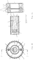
- the compression spring 4 Due to the Preload the compression spring 4 is a surface of the pin 6 frictionally against the leading edge 7, so that a further axial movement of the actuating element 3 from the opening of the cavity 2 out, ie in the drawing to the right, is prevented and enters in this direction a blocking effect ,
- One of the surface of the pin 6, the non-positively applied to the leading edge 7, opposite surface of the pin 6 is frictionally against a surface of the fastener. This is a side surface of the passage through the outer wall of the shaft 1, through which the pin 6 protrudes radially beyond the shaft surface. The interaction of the leading edge 7, the pin 6 and the implementation prevents the pin 6 changes its radial position without external force.
- FIG. 1b is a front view too FIG. 1a , Again, shaft 1, cavity 2 and the actuator 3 can be seen. According to the axial position of the actuating element 3, the engagement means 6 protrudes radially beyond the shaft 1.
- Conveyor roller 9 and gear 10 are connected to each other via pins 13, which engage him recordings 14 of the roller 9.
- guide grooves 11 and 12 are provided, which are assembled for the guidance of wires with different profiles. They are arranged symmetrically to the axial center of the roller 9.
- the compression spring 4 is shown compressed by an external force.
- the resulting axial position of the actuating element 3 causes the pin 6 with the lateral surface of the cylindrical shaft 1 closes.
- the wire feed roller 9 and the gear 10 can be pushed onto the shaft.
- the hub-shaped member 15 of the shaft first deduct if it's postponed to this.
- the connection of shaft 1 and hub-shaped component 15 is thus released.
- FIG. 3a shows a side view of the embodiment of the invention FIG. 2a , wherein the actuating element 3 is in a Malawib, the connection securing axial position (see. FIGS. 1a and 1b ).
- the component 15 is pushed. After pushing on roller 9 and gear 10, the necessary force on the actuating element 3 was turned off.
- the engagement means 6 has therefore assumed its second, the connection securing radial position due to the bias of the compression spring 4.
- the result is a positive connection between the pin 6 as an engagement means and a radially extending side surface of the roller 9.
- the position of the component 15 is on the shaft 1 in an axial direction (in the drawing to the right) secured.
- the bias of the compression spring 4 fixes the actuator 3 in the first axial position shown here, since no external movement of the actuating means 3 between the compression spring 5 and the non-positively applied to the leading edge 7 pin 6 is possible.
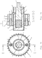
- FIG. 4a shows a further embodiment of the invention, wherein the actuator 23 is in the first, the compound securing axial position.
- Actuating element 23 and counter-pressure element are accommodated in this example in a cavity of a shaft 1.
- a jacket surface 25 of a section 24 of the actuating element 23 facing the opening of the cavity 2 ends with a cylindrical inner surface 29 of the fastening element 1 delimiting the cavity 2. Consequently, the mechanics of the fastener is partially obscured. Thus, no foreign matter can penetrate into the fastening mechanism and at the same time the risk of injury to the operator is reduced.
- the engagement means is configured in this embodiment as a ball 26.
- a different geometry was selected than in the first embodiment.
- a starting element 27 is mounted so that it follows rotational movements of the shaft with the least possible slip.
- the gear 10 is applied to the starting element 27.
- the roller 9 is pushed and connected via pins 13 which engage in the holes 14 with him.
- the ball 26 secures the connection between the shaft 1 and the component 15 on the side of the shaft 1 opposite the starting element 27.
- the component 15 is thus arranged between the starting element 27 and the ball 26 as engaging means.
Claims (14)
- Dispositif d'acheminement de fil de soudure comportant un arbre (1) et un élément de fixation associé à l'arbre (1) pour le raccordement de l'arbre (1) à un composant (15) en forme de moyeu configuré en tant que rouleau (9), où l'élément de fixation présente une cavité (2), en particulier cylindrique, dont au moins un côté est ouvert, dans laquelle est agencé un élément d'actionnement (3, 23), caractérisé en ce que l'élément d'actionnement (3, 23) présente une section axiale (8, 28) d'une dimension se rétrécissant radialement, le long de laquelle glisse un moyen d'engagement (6, 26) s'étendant radialement par rapport à l'élément d'actionnement (3, 23), et qui est agencé de manière à pouvoir être déplacé axialement de telle sorte que, dans une première position axiale de l'élément d'actionnement (3, 23) assurant le raccordement, le moyen d'engagement (6, 26) est en contact par complémentarité de forme avec le composant (15) en forme de moyeu et que, dans une deuxième position axiale de l'élément d'actionnement (3, 23) libérant le raccordement, le moyen d'engagement (6, 26) n'est pas dans une complémentarité de forme, étant entendu qu'un élément de blocage est prévu sur l'élément d'actionnement (3, 23) et est réalisé sous la forme d'un bord de contact (7) destiné à restreindre le mouvement axial de l'élément d'actionnement (3, 23), et étant entendu que l'effet de blocage se produit lorsqu'une surface du moyen d'engagement (6, 26) repose sur le bord de contact (7).
- Dispositif selon la revendication 1, caractérisé en ce que l'élément d'actionnement (3, 23) peut être fixé dans la première position axiale assurant le raccordement.
- Dispositif selon la revendication 2, caractérisé en ce que l'élément d'actionnement (3, 23) est agencé axialement de façon à pouvoir être déplacé dans la cavité (2) contre une force de précontrainte d'un élément de contre-pression (4), où l'élément d'actionnement (3, 23) est sous tension dans la première position axiale assurant le raccordement et peut être transféré, sous l'effet d'une force externe dirigée à l'opposé de la tension, dans la deuxième position axiale libérant le raccordement.
- Dispositif selon la revendication 3, caractérisé en ce que l'élément de contre-pression est réalisé sous la forme d'un ressort de pression (4), agencé entre l'élément d'actionnement (3, 23) et une paroi intérieure (5) de la cavité (2) s'étendant en direction radiale.
- Dispositif selon l'une quelconque des revendications précédentes, caractérisé en ce que la section axiale (8) de l'élément d'actionnement (3) d'une dimension se rétrécissant radialement est la surface enveloppante d'un tronc de cône.
- Dispositif selon l'une quelconque des revendications précédentes, caractérisé en ce qu'une surface enveloppante (25) d'une section (24) de l'élément d'actionnement (23) dirigée vers l'ouverture de la cavité (2) se termine par une surface intérieure (29) de l'élément de fixation (1), en particulier cylindrique, délimitant la cavité (2).
- Dispositif selon l'une quelconque des revendications 1 à 6, caractérisé en ce que la surface du moyen d'engagement (6, 26) s'appuie par liaison de force, dans la première position axiale de l'élément d'actionnement (3, 23) assurant le raccordement, sur le bord de contact (7), et en ce qu'une surface du moyen d'engagement (6, 26) opposée à cette surface s'appuie par liaison de force sur une surface de l'élément de fixation.
- Dispositif selon l'une quelconque des revendications précédentes, caractérisé en ce que l'élément de fixation et l'arbre (1) sont conçus d'une seule pièce.
- Dispositif selon l'une quelconque des revendications précédentes, caractérisé en ce que le composant (15) présente une protubérance qui correspond au moyen d'engagement (6, 26).
- Dispositif selon l'une quelconque des revendications 1 à 8, caractérisé en ce que le moyen d'engagement (6, 26) s'appuie par complémentarité de forme sur une face interne du composant (9).
- Dispositif selon l'une quelconque des revendications 1 à 8, caractérisé en ce que le moyen d'engagement (6, 26) peut être positionné en direction axiale devant ou derrière le composant (15) et s'appuie par complémentarité de forme sur une face latérale externe du composant (9), en particulier une face latérale externe s'étendant radialement.
- Dispositif selon l'une quelconque des revendications précédentes, caractérisé en ce que l'on prévoit un élément de contact (27) sur l'élément de fixation ou sur l'arbre (1).
- Dispositif selon la revendication 12, caractérisé en ce que le composant (15) est agencé axialement entre l'élément de contact (27) et le moyen d'engagement (26) et en ce que la distance axiale entre le moyen d'engagement (26) et l'élément de contact (27) est choisie de telle sorte que lors d'une complémentarité de forme du composant (15) et du moyen d'engagement (26), le composant (15) est relié par liaison de force à l'élément de contact (27).
- Dispositif selon l'une quelconque des revendications précédentes, caractérisé en ce que le rouleau (15) est conçu en tant que rouleau d'acheminement de fil (9) qui présente deux rainures de guidage (11,12) agencées parallèlement et symétriquement par rapport au milieu axial du rouleau (9) pour des profils de fil différents.
Priority Applications (1)
| Application Number | Priority Date | Filing Date | Title |
|---|---|---|---|
| EP11150922.0A EP2476500B1 (fr) | 2011-01-14 | 2011-01-14 | Dispositif d'approvisionnement en fil de soudage |
Applications Claiming Priority (1)
| Application Number | Priority Date | Filing Date | Title |
|---|---|---|---|
| EP11150922.0A EP2476500B1 (fr) | 2011-01-14 | 2011-01-14 | Dispositif d'approvisionnement en fil de soudage |
Publications (2)
| Publication Number | Publication Date |
|---|---|
| EP2476500A1 EP2476500A1 (fr) | 2012-07-18 |
| EP2476500B1 true EP2476500B1 (fr) | 2018-03-14 |
Family
ID=44123293
Family Applications (1)
| Application Number | Title | Priority Date | Filing Date |
|---|---|---|---|
| EP11150922.0A Not-in-force EP2476500B1 (fr) | 2011-01-14 | 2011-01-14 | Dispositif d'approvisionnement en fil de soudage |
Country Status (1)
| Country | Link |
|---|---|
| EP (1) | EP2476500B1 (fr) |
Cited By (1)
| Publication number | Priority date | Publication date | Assignee | Title |
|---|---|---|---|---|
| US11969836B2 (en) | 2020-08-04 | 2024-04-30 | Illinois Tool Works Inc. | Reciprocating wire feed welding system and method |
Families Citing this family (8)
| Publication number | Priority date | Publication date | Assignee | Title |
|---|---|---|---|---|
| US10081072B2 (en) | 2011-03-29 | 2018-09-25 | Illinois Tool Works Inc. | Welding torch with wire feed speed control |
| US10239148B2 (en) | 2012-06-14 | 2019-03-26 | Illinois Tool Works Inc. | Motor assembly for a push-pull welding torch |
| US9463524B2 (en) | 2012-06-14 | 2016-10-11 | Illinois Tool Works Inc. | System and method for adjusting feed roll position in a welding torch |
| US9931706B2 (en) | 2013-03-12 | 2018-04-03 | Illinois Tool Works Inc. | Adjustable drive shaft assembly |
| US9616516B2 (en) * | 2013-07-11 | 2017-04-11 | Illinois Tool Works Inc. | Indexing drive roll carrier system and method |
| DE102015111443B8 (de) * | 2015-07-15 | 2019-05-29 | Powerslide Gmbh | Achssystem für ein Rollsportgerät |
| US10730132B2 (en) | 2015-12-28 | 2020-08-04 | Illinois Tool Works Inc. | Reciprocating wire feed welding system and method |
| US10675698B2 (en) | 2015-12-31 | 2020-06-09 | Illinois Tool Works Inc. | Wire delivery apparatus with a non-rotational actuator |
Citations (4)
| Publication number | Priority date | Publication date | Assignee | Title |
|---|---|---|---|---|
| US5988656A (en) * | 1998-03-16 | 1999-11-23 | K-2 Corporation | Quick release skate axle |
| DE202005000128U1 (de) * | 2005-01-05 | 2005-03-17 | Lee Yi Min | Ratschenschlüssel, der eine Schraubhülse schnell freigeben kann |
| US20050218129A1 (en) * | 2004-04-05 | 2005-10-06 | Kensrue Milo M | Spindle and spool for welding gun |
| US20080079231A1 (en) * | 2006-09-28 | 2008-04-03 | Felty Paul G | Skateboard wheel and axle assembly |
Family Cites Families (3)
| Publication number | Priority date | Publication date | Assignee | Title |
|---|---|---|---|---|
| ES2067389B1 (es) * | 1993-02-23 | 1998-03-01 | Navas Antonio Guerra | Buje para ruedas de bicicletas. |
| US7389900B2 (en) * | 2004-04-08 | 2008-06-24 | Illinois Tool Works Inc. | Floating wire guides |
| US7574768B2 (en) * | 2006-07-18 | 2009-08-18 | Kimberly-Clark Worldwide, Inc. | Quick-release handle and interchangeable cleaning system |
-
2011
- 2011-01-14 EP EP11150922.0A patent/EP2476500B1/fr not_active Not-in-force
Patent Citations (4)
| Publication number | Priority date | Publication date | Assignee | Title |
|---|---|---|---|---|
| US5988656A (en) * | 1998-03-16 | 1999-11-23 | K-2 Corporation | Quick release skate axle |
| US20050218129A1 (en) * | 2004-04-05 | 2005-10-06 | Kensrue Milo M | Spindle and spool for welding gun |
| DE202005000128U1 (de) * | 2005-01-05 | 2005-03-17 | Lee Yi Min | Ratschenschlüssel, der eine Schraubhülse schnell freigeben kann |
| US20080079231A1 (en) * | 2006-09-28 | 2008-04-03 | Felty Paul G | Skateboard wheel and axle assembly |
Cited By (1)
| Publication number | Priority date | Publication date | Assignee | Title |
|---|---|---|---|---|
| US11969836B2 (en) | 2020-08-04 | 2024-04-30 | Illinois Tool Works Inc. | Reciprocating wire feed welding system and method |
Also Published As
| Publication number | Publication date |
|---|---|
| EP2476500A1 (fr) | 2012-07-18 |
Similar Documents
| Publication | Publication Date | Title |
|---|---|---|
| EP2476500B1 (fr) | Dispositif d'approvisionnement en fil de soudage | |
| EP2823203B1 (fr) | Unité de verrouillage, en particulier pour un frein de stationnement d'une boîte de vitesses automatique | |
| EP1659298B1 (fr) | Entraînement linéaire | |
| EP1799396B1 (fr) | Dispositif de remplacement pour tetes de serrage comportant plusieurs machoires de serrage | |
| EP3717786B1 (fr) | Dispositif de compensation de tolérance avec sécurité par serrage | |
| EP0362566B1 (fr) | Support élastique | |
| DE202006013666U1 (de) | Schnellverschluss zum Verbinden zweier Bauteile | |
| EP2320100B1 (fr) | Barre de traction-compression | |
| EP2041852B1 (fr) | Interrupteur avec un accouplement pour l'organe de commande | |
| DE102012112610A1 (de) | Rastbolzen | |
| EP2878844A2 (fr) | Frein à disque | |
| EP1905545A2 (fr) | Tendeur à ressort pour ressort cylindrique | |
| EP2031156B1 (fr) | Mécanisme de rappel pour une poignée de porte | |
| DE102018114289A1 (de) | Zentrifuge | |
| EP3224510B1 (fr) | Système de soupape | |
| DE2707124C2 (de) | Manuelle Nachstellvorrichtung für den Bremsbelagverschleiß einer mechanisch betätigbaren Schwimmsattel-Scheibenbremse | |
| DE202010008858U1 (de) | Zug-Druck-Stange | |
| EP2578891B1 (fr) | Adapteur | |
| EP0215295A1 (fr) | Accouplement pour l'assemblage détachable d'un manche de pièce à main dentaire avec une tête | |
| DE102021100753B3 (de) | Joystick mit verschleißausgleichendem Gleitelement | |
| DE3802154C2 (fr) | ||
| DE10032668A1 (de) | Reibscheiben-Kupplung mit einer Nachstelleinrichtung zum Ausgleich von Reibflächen-Verschleiß | |
| DE102019103916A1 (de) | Greif- oder Spannvorrichtung mit einer Brems- und/oder Festsetzeinheit | |
| DE102018114309A1 (de) | Bremsvorrichtung | |
| EP3636863B1 (fr) | Fixation de joint |
Legal Events
| Date | Code | Title | Description |
|---|---|---|---|
| PUAI | Public reference made under article 153(3) epc to a published international application that has entered the european phase |
Free format text: ORIGINAL CODE: 0009012 |
|
| 17P | Request for examination filed |
Effective date: 20110901 |
|
| AK | Designated contracting states |
Kind code of ref document: A1 Designated state(s): AL AT BE BG CH CY CZ DE DK EE ES FI FR GB GR HR HU IE IS IT LI LT LU LV MC MK MT NL NO PL PT RO RS SE SI SK SM TR |
|
| AX | Request for extension of the european patent |
Extension state: BA ME |
|
| 17Q | First examination report despatched |
Effective date: 20130711 |
|
| RAP1 | Party data changed (applicant data changed or rights of an application transferred) |
Owner name: EWM AG |
|
| GRAP | Despatch of communication of intention to grant a patent |
Free format text: ORIGINAL CODE: EPIDOSNIGR1 |
|
| STAA | Information on the status of an ep patent application or granted ep patent |
Free format text: STATUS: GRANT OF PATENT IS INTENDED |
|
| INTG | Intention to grant announced |
Effective date: 20170406 |
|
| GRAJ | Information related to disapproval of communication of intention to grant by the applicant or resumption of examination proceedings by the epo deleted |
Free format text: ORIGINAL CODE: EPIDOSDIGR1 |
|
| STAA | Information on the status of an ep patent application or granted ep patent |
Free format text: STATUS: EXAMINATION IS IN PROGRESS |
|
| GRAP | Despatch of communication of intention to grant a patent |
Free format text: ORIGINAL CODE: EPIDOSNIGR1 |
|
| STAA | Information on the status of an ep patent application or granted ep patent |
Free format text: STATUS: GRANT OF PATENT IS INTENDED |
|
| INTC | Intention to grant announced (deleted) | ||
| INTG | Intention to grant announced |
Effective date: 20170921 |
|
| GRAS | Grant fee paid |
Free format text: ORIGINAL CODE: EPIDOSNIGR3 |
|
| GRAA | (expected) grant |
Free format text: ORIGINAL CODE: 0009210 |
|
| STAA | Information on the status of an ep patent application or granted ep patent |
Free format text: STATUS: THE PATENT HAS BEEN GRANTED |
|
| AK | Designated contracting states |
Kind code of ref document: B1 Designated state(s): AL AT BE BG CH CY CZ DE DK EE ES FI FR GB GR HR HU IE IS IT LI LT LU LV MC MK MT NL NO PL PT RO RS SE SI SK SM TR |
|
| REG | Reference to a national code |
Ref country code: GB Ref legal event code: FG4D Free format text: NOT ENGLISH |
|
| REG | Reference to a national code |
Ref country code: AT Ref legal event code: REF Ref document number: 978374 Country of ref document: AT Kind code of ref document: T Effective date: 20180315 Ref country code: CH Ref legal event code: EP |
|
| REG | Reference to a national code |
Ref country code: IE Ref legal event code: FG4D Free format text: LANGUAGE OF EP DOCUMENT: GERMAN |
|
| REG | Reference to a national code |
Ref country code: DE Ref legal event code: R096 Ref document number: 502011013884 Country of ref document: DE |
|
| REG | Reference to a national code |
Ref country code: NL Ref legal event code: MP Effective date: 20180314 |
|
| REG | Reference to a national code |
Ref country code: LT Ref legal event code: MG4D |
|
| PG25 | Lapsed in a contracting state [announced via postgrant information from national office to epo] |
Ref country code: FI Free format text: LAPSE BECAUSE OF FAILURE TO SUBMIT A TRANSLATION OF THE DESCRIPTION OR TO PAY THE FEE WITHIN THE PRESCRIBED TIME-LIMIT Effective date: 20180314 Ref country code: CY Free format text: LAPSE BECAUSE OF FAILURE TO SUBMIT A TRANSLATION OF THE DESCRIPTION OR TO PAY THE FEE WITHIN THE PRESCRIBED TIME-LIMIT Effective date: 20180314 Ref country code: HR Free format text: LAPSE BECAUSE OF FAILURE TO SUBMIT A TRANSLATION OF THE DESCRIPTION OR TO PAY THE FEE WITHIN THE PRESCRIBED TIME-LIMIT Effective date: 20180314 Ref country code: NO Free format text: LAPSE BECAUSE OF FAILURE TO SUBMIT A TRANSLATION OF THE DESCRIPTION OR TO PAY THE FEE WITHIN THE PRESCRIBED TIME-LIMIT Effective date: 20180614 Ref country code: LT Free format text: LAPSE BECAUSE OF FAILURE TO SUBMIT A TRANSLATION OF THE DESCRIPTION OR TO PAY THE FEE WITHIN THE PRESCRIBED TIME-LIMIT Effective date: 20180314 Ref country code: ES Free format text: LAPSE BECAUSE OF FAILURE TO SUBMIT A TRANSLATION OF THE DESCRIPTION OR TO PAY THE FEE WITHIN THE PRESCRIBED TIME-LIMIT Effective date: 20180314 |
|
| PG25 | Lapsed in a contracting state [announced via postgrant information from national office to epo] |
Ref country code: BG Free format text: LAPSE BECAUSE OF FAILURE TO SUBMIT A TRANSLATION OF THE DESCRIPTION OR TO PAY THE FEE WITHIN THE PRESCRIBED TIME-LIMIT Effective date: 20180614 Ref country code: GR Free format text: LAPSE BECAUSE OF FAILURE TO SUBMIT A TRANSLATION OF THE DESCRIPTION OR TO PAY THE FEE WITHIN THE PRESCRIBED TIME-LIMIT Effective date: 20180615 Ref country code: LV Free format text: LAPSE BECAUSE OF FAILURE TO SUBMIT A TRANSLATION OF THE DESCRIPTION OR TO PAY THE FEE WITHIN THE PRESCRIBED TIME-LIMIT Effective date: 20180314 Ref country code: SE Free format text: LAPSE BECAUSE OF FAILURE TO SUBMIT A TRANSLATION OF THE DESCRIPTION OR TO PAY THE FEE WITHIN THE PRESCRIBED TIME-LIMIT Effective date: 20180314 Ref country code: RS Free format text: LAPSE BECAUSE OF FAILURE TO SUBMIT A TRANSLATION OF THE DESCRIPTION OR TO PAY THE FEE WITHIN THE PRESCRIBED TIME-LIMIT Effective date: 20180314 |
|
| PG25 | Lapsed in a contracting state [announced via postgrant information from national office to epo] |
Ref country code: MT Free format text: LAPSE BECAUSE OF FAILURE TO SUBMIT A TRANSLATION OF THE DESCRIPTION OR TO PAY THE FEE WITHIN THE PRESCRIBED TIME-LIMIT Effective date: 20180314 |
|
| PG25 | Lapsed in a contracting state [announced via postgrant information from national office to epo] |
Ref country code: EE Free format text: LAPSE BECAUSE OF FAILURE TO SUBMIT A TRANSLATION OF THE DESCRIPTION OR TO PAY THE FEE WITHIN THE PRESCRIBED TIME-LIMIT Effective date: 20180314 Ref country code: NL Free format text: LAPSE BECAUSE OF FAILURE TO SUBMIT A TRANSLATION OF THE DESCRIPTION OR TO PAY THE FEE WITHIN THE PRESCRIBED TIME-LIMIT Effective date: 20180314 Ref country code: AL Free format text: LAPSE BECAUSE OF FAILURE TO SUBMIT A TRANSLATION OF THE DESCRIPTION OR TO PAY THE FEE WITHIN THE PRESCRIBED TIME-LIMIT Effective date: 20180314 Ref country code: PL Free format text: LAPSE BECAUSE OF FAILURE TO SUBMIT A TRANSLATION OF THE DESCRIPTION OR TO PAY THE FEE WITHIN THE PRESCRIBED TIME-LIMIT Effective date: 20180314 Ref country code: RO Free format text: LAPSE BECAUSE OF FAILURE TO SUBMIT A TRANSLATION OF THE DESCRIPTION OR TO PAY THE FEE WITHIN THE PRESCRIBED TIME-LIMIT Effective date: 20180314 |
|
| PG25 | Lapsed in a contracting state [announced via postgrant information from national office to epo] |
Ref country code: SK Free format text: LAPSE BECAUSE OF FAILURE TO SUBMIT A TRANSLATION OF THE DESCRIPTION OR TO PAY THE FEE WITHIN THE PRESCRIBED TIME-LIMIT Effective date: 20180314 Ref country code: CZ Free format text: LAPSE BECAUSE OF FAILURE TO SUBMIT A TRANSLATION OF THE DESCRIPTION OR TO PAY THE FEE WITHIN THE PRESCRIBED TIME-LIMIT Effective date: 20180314 Ref country code: SM Free format text: LAPSE BECAUSE OF FAILURE TO SUBMIT A TRANSLATION OF THE DESCRIPTION OR TO PAY THE FEE WITHIN THE PRESCRIBED TIME-LIMIT Effective date: 20180314 |
|
| REG | Reference to a national code |
Ref country code: DE Ref legal event code: R097 Ref document number: 502011013884 Country of ref document: DE |
|
| PG25 | Lapsed in a contracting state [announced via postgrant information from national office to epo] |
Ref country code: PT Free format text: LAPSE BECAUSE OF FAILURE TO SUBMIT A TRANSLATION OF THE DESCRIPTION OR TO PAY THE FEE WITHIN THE PRESCRIBED TIME-LIMIT Effective date: 20180716 |
|
| PLBE | No opposition filed within time limit |
Free format text: ORIGINAL CODE: 0009261 |
|
| STAA | Information on the status of an ep patent application or granted ep patent |
Free format text: STATUS: NO OPPOSITION FILED WITHIN TIME LIMIT |
|
| PG25 | Lapsed in a contracting state [announced via postgrant information from national office to epo] |
Ref country code: DK Free format text: LAPSE BECAUSE OF FAILURE TO SUBMIT A TRANSLATION OF THE DESCRIPTION OR TO PAY THE FEE WITHIN THE PRESCRIBED TIME-LIMIT Effective date: 20180314 |
|
| 26N | No opposition filed |
Effective date: 20181217 |
|
| PG25 | Lapsed in a contracting state [announced via postgrant information from national office to epo] |
Ref country code: SI Free format text: LAPSE BECAUSE OF FAILURE TO SUBMIT A TRANSLATION OF THE DESCRIPTION OR TO PAY THE FEE WITHIN THE PRESCRIBED TIME-LIMIT Effective date: 20180314 |
|
| PG25 | Lapsed in a contracting state [announced via postgrant information from national office to epo] |
Ref country code: MC Free format text: LAPSE BECAUSE OF FAILURE TO SUBMIT A TRANSLATION OF THE DESCRIPTION OR TO PAY THE FEE WITHIN THE PRESCRIBED TIME-LIMIT Effective date: 20180314 |
|
| REG | Reference to a national code |
Ref country code: CH Ref legal event code: PL |
|
| PG25 | Lapsed in a contracting state [announced via postgrant information from national office to epo] |
Ref country code: LU Free format text: LAPSE BECAUSE OF NON-PAYMENT OF DUE FEES Effective date: 20190114 |
|
| REG | Reference to a national code |
Ref country code: BE Ref legal event code: MM Effective date: 20190131 |
|
| REG | Reference to a national code |
Ref country code: IE Ref legal event code: MM4A |
|
| PG25 | Lapsed in a contracting state [announced via postgrant information from national office to epo] |
Ref country code: BE Free format text: LAPSE BECAUSE OF NON-PAYMENT OF DUE FEES Effective date: 20190131 |
|
| PG25 | Lapsed in a contracting state [announced via postgrant information from national office to epo] |
Ref country code: LI Free format text: LAPSE BECAUSE OF NON-PAYMENT OF DUE FEES Effective date: 20190131 Ref country code: CH Free format text: LAPSE BECAUSE OF NON-PAYMENT OF DUE FEES Effective date: 20190131 |
|
| PG25 | Lapsed in a contracting state [announced via postgrant information from national office to epo] |
Ref country code: IE Free format text: LAPSE BECAUSE OF NON-PAYMENT OF DUE FEES Effective date: 20190114 |
|
| PGFP | Annual fee paid to national office [announced via postgrant information from national office to epo] |
Ref country code: FR Payment date: 20191218 Year of fee payment: 10 |
|
| REG | Reference to a national code |
Ref country code: AT Ref legal event code: MM01 Ref document number: 978374 Country of ref document: AT Kind code of ref document: T Effective date: 20190114 |
|
| PG25 | Lapsed in a contracting state [announced via postgrant information from national office to epo] |
Ref country code: TR Free format text: LAPSE BECAUSE OF FAILURE TO SUBMIT A TRANSLATION OF THE DESCRIPTION OR TO PAY THE FEE WITHIN THE PRESCRIBED TIME-LIMIT Effective date: 20180314 |
|
| PG25 | Lapsed in a contracting state [announced via postgrant information from national office to epo] |
Ref country code: AT Free format text: LAPSE BECAUSE OF NON-PAYMENT OF DUE FEES Effective date: 20190114 |
|
| PGFP | Annual fee paid to national office [announced via postgrant information from national office to epo] |
Ref country code: DE Payment date: 20191218 Year of fee payment: 10 Ref country code: GB Payment date: 20191219 Year of fee payment: 10 Ref country code: IT Payment date: 20200114 Year of fee payment: 10 |
|
| PG25 | Lapsed in a contracting state [announced via postgrant information from national office to epo] |
Ref country code: IS Free format text: LAPSE BECAUSE OF FAILURE TO SUBMIT A TRANSLATION OF THE DESCRIPTION OR TO PAY THE FEE WITHIN THE PRESCRIBED TIME-LIMIT Effective date: 20180714 |
|
| PG25 | Lapsed in a contracting state [announced via postgrant information from national office to epo] |
Ref country code: HU Free format text: LAPSE BECAUSE OF FAILURE TO SUBMIT A TRANSLATION OF THE DESCRIPTION OR TO PAY THE FEE WITHIN THE PRESCRIBED TIME-LIMIT; INVALID AB INITIO Effective date: 20110114 |
|
| REG | Reference to a national code |
Ref country code: DE Ref legal event code: R119 Ref document number: 502011013884 Country of ref document: DE |
|
| GBPC | Gb: european patent ceased through non-payment of renewal fee |
Effective date: 20210114 |
|
| PG25 | Lapsed in a contracting state [announced via postgrant information from national office to epo] |
Ref country code: FR Free format text: LAPSE BECAUSE OF NON-PAYMENT OF DUE FEES Effective date: 20210131 |
|
| PG25 | Lapsed in a contracting state [announced via postgrant information from national office to epo] |
Ref country code: GB Free format text: LAPSE BECAUSE OF NON-PAYMENT OF DUE FEES Effective date: 20210114 Ref country code: DE Free format text: LAPSE BECAUSE OF NON-PAYMENT OF DUE FEES Effective date: 20210803 |
|
| PG25 | Lapsed in a contracting state [announced via postgrant information from national office to epo] |
Ref country code: IT Free format text: LAPSE BECAUSE OF NON-PAYMENT OF DUE FEES Effective date: 20210114 |
|
| PG25 | Lapsed in a contracting state [announced via postgrant information from national office to epo] |
Ref country code: MK Free format text: LAPSE BECAUSE OF FAILURE TO SUBMIT A TRANSLATION OF THE DESCRIPTION OR TO PAY THE FEE WITHIN THE PRESCRIBED TIME-LIMIT Effective date: 20180314 |