EP2476498B1 - Automatic clipping line - Google Patents
Automatic clipping line Download PDFInfo
- Publication number
- EP2476498B1 EP2476498B1 EP12163938.9A EP12163938A EP2476498B1 EP 2476498 B1 EP2476498 B1 EP 2476498B1 EP 12163938 A EP12163938 A EP 12163938A EP 2476498 B1 EP2476498 B1 EP 2476498B1
- Authority
- EP
- European Patent Office
- Prior art keywords
- sheets
- veneer
- sheet
- conveyor
- trimming
- Prior art date
- Legal status (The legal status is an assumption and is not a legal conclusion. Google has not performed a legal analysis and makes no representation as to the accuracy of the status listed.)
- Not-in-force
Links
- 238000009966 trimming Methods 0.000 claims description 21
- 238000000034 method Methods 0.000 claims description 20
- 239000002023 wood Substances 0.000 claims description 8
- 230000001678 irradiating effect Effects 0.000 claims 2
- 230000005855 radiation Effects 0.000 claims 2
- 230000005540 biological transmission Effects 0.000 description 11
- 239000002699 waste material Substances 0.000 description 10
- 238000011144 upstream manufacturing Methods 0.000 description 6
- 239000012530 fluid Substances 0.000 description 3
- 238000003384 imaging method Methods 0.000 description 3
- 230000000712 assembly Effects 0.000 description 2
- 238000000429 assembly Methods 0.000 description 2
- 230000002452 interceptive effect Effects 0.000 description 2
- 208000019300 CLIPPERS Diseases 0.000 description 1
- 208000021930 chronic lymphocytic inflammation with pontine perivascular enhancement responsive to steroids Diseases 0.000 description 1
- 239000004020 conductor Substances 0.000 description 1
- 230000008878 coupling Effects 0.000 description 1
- 238000010168 coupling process Methods 0.000 description 1
- 238000005859 coupling reaction Methods 0.000 description 1
- 230000001419 dependent effect Effects 0.000 description 1
- 238000011161 development Methods 0.000 description 1
- 230000018109 developmental process Effects 0.000 description 1
- 230000000694 effects Effects 0.000 description 1
- 238000005457 optimization Methods 0.000 description 1
- 230000002093 peripheral effect Effects 0.000 description 1
- 229910001220 stainless steel Inorganic materials 0.000 description 1
- 239000010935 stainless steel Substances 0.000 description 1
- 230000001360 synchronised effect Effects 0.000 description 1
Images



Classifications
-
- B—PERFORMING OPERATIONS; TRANSPORTING
- B27—WORKING OR PRESERVING WOOD OR SIMILAR MATERIAL; NAILING OR STAPLING MACHINES IN GENERAL
- B27L—REMOVING BARK OR VESTIGES OF BRANCHES; SPLITTING WOOD; MANUFACTURE OF VENEER, WOODEN STICKS, WOOD SHAVINGS, WOOD FIBRES OR WOOD POWDER
- B27L5/00—Manufacture of veneer ; Preparatory processing therefor
- B27L5/08—Severing sheets or segments from veneer strips; Shearing devices therefor; Making veneer blanks, e.g. trimming to size
-
- B—PERFORMING OPERATIONS; TRANSPORTING
- B23—MACHINE TOOLS; METAL-WORKING NOT OTHERWISE PROVIDED FOR
- B23D—PLANING; SLOTTING; SHEARING; BROACHING; SAWING; FILING; SCRAPING; LIKE OPERATIONS FOR WORKING METAL BY REMOVING MATERIAL, NOT OTHERWISE PROVIDED FOR
- B23D45/00—Sawing machines or sawing devices with circular saw blades or with friction saw discs
- B23D45/04—Sawing machines or sawing devices with circular saw blades or with friction saw discs with a circular saw blade or the stock carried by a pivoted lever
- B23D45/042—Sawing machines or sawing devices with circular saw blades or with friction saw discs with a circular saw blade or the stock carried by a pivoted lever with the saw blade carried by a pivoted lever
-
- B—PERFORMING OPERATIONS; TRANSPORTING
- B27—WORKING OR PRESERVING WOOD OR SIMILAR MATERIAL; NAILING OR STAPLING MACHINES IN GENERAL
- B27B—SAWS FOR WOOD OR SIMILAR MATERIAL; COMPONENTS OR ACCESSORIES THEREFOR
- B27B31/00—Arrangements for conveying, loading, turning, adjusting, or discharging the log or timber, specially designed for saw mills or sawing machines
- B27B31/06—Adjusting equipment, e.g. using optical projection
-
- B—PERFORMING OPERATIONS; TRANSPORTING
- B27—WORKING OR PRESERVING WOOD OR SIMILAR MATERIAL; NAILING OR STAPLING MACHINES IN GENERAL
- B27B—SAWS FOR WOOD OR SIMILAR MATERIAL; COMPONENTS OR ACCESSORIES THEREFOR
- B27B5/00—Sawing machines working with circular or cylindrical saw blades; Components or equipment therefor
- B27B5/02—Sawing machines working with circular or cylindrical saw blades; Components or equipment therefor characterised by a special purpose only
- B27B5/04—Sawing machines working with circular or cylindrical saw blades; Components or equipment therefor characterised by a special purpose only for edge trimming
-
- B—PERFORMING OPERATIONS; TRANSPORTING
- B27—WORKING OR PRESERVING WOOD OR SIMILAR MATERIAL; NAILING OR STAPLING MACHINES IN GENERAL
- B27B—SAWS FOR WOOD OR SIMILAR MATERIAL; COMPONENTS OR ACCESSORIES THEREFOR
- B27B5/00—Sawing machines working with circular or cylindrical saw blades; Components or equipment therefor
- B27B5/02—Sawing machines working with circular or cylindrical saw blades; Components or equipment therefor characterised by a special purpose only
- B27B5/06—Sawing machines working with circular or cylindrical saw blades; Components or equipment therefor characterised by a special purpose only for dividing plates in parts of determined size, e.g. panels
-
- B—PERFORMING OPERATIONS; TRANSPORTING
- B27—WORKING OR PRESERVING WOOD OR SIMILAR MATERIAL; NAILING OR STAPLING MACHINES IN GENERAL
- B27G—ACCESSORY MACHINES OR APPARATUS FOR WORKING WOOD OR SIMILAR MATERIALS; TOOLS FOR WORKING WOOD OR SIMILAR MATERIALS; SAFETY DEVICES FOR WOOD WORKING MACHINES OR TOOLS
- B27G1/00—Machines or devices for removing knots or other irregularities or for filling-up holes
Definitions
- This invention relates to a method for scanning at least one sheet of wood veneer according to the preamble of claim 1.
- the invention also relates to an apparatus according to the preamble of claim 12 for carrying-out such a method.
- sheets of wood veneer have been trimmed using guillotine-type clippers.
- stacked sheets of wood veneer hereinafter sometimes referred to as books of veneer
- the books may be split, for example, by parallel connected circular saws positioned in a row transverse to the direction of the cuts.
- EP 0 500 161 A2 describes a method for cutting sheets from a strip of wood veneer comprising the phases of detecting the presence of a plurality of specific zones of the strip and cutting the strip transversely on command or, in combination, longitudinally and transversely, to circumscribe specific zones of said plurality in strips as wide as the entire strip or a fraction thereof.
- a book of veneer 108 is conveyed along a conveyor 110 through a scanner housing 112, where the book of veneer 108 is illuminated by lamps 114, which may include fluorescent and ultraviolet (blacklight) lamps, and scanned by imaging devices 116, such as cameras 116-1 and the like, for detecting the wane edge of a book 108, and areas of contrast, such as heartwood, flaws, knots and the like, which it is desired to trim from the book 108.
- Imaging devices 116 may include one or more laser detectors 116-2 for detecting, for example, the leading and trailing edges of a book 108, and thus the width of the book 108, as the book 108 is conveyed through housing 112 on conveyor 110.
- the computer 118 calculates a trimming solution for the book 108 in an effort to optimize the value of veneer yielded by the book 108.
- the inside of housing 112 may be finished matte black to reduce internal reflections.
- Two cameras 116-1 are mounted at each end of housing 112. Lasers 116-2 are placed along the centerline of housing 112 above conveyor 110. Belts of conveyor 110 convey the book of veneer 108 across housing 112.
- the book of veneer 108 may optionally be manually marked, for example, with fluorescent chalk, by an operator before the book of veneer 108 enters housing 112. According to the invention if such marking is detected on the book of veneer 108, computer 118 is programmed so that that marking overrides the optimization solution provided by computer 118.
- a series of fetchers 120 are projected by motor(s) 121, such as (a) pneumatic or hydraulic piston-and-cylinder motor(s) or motor-driven ballscrew(s) or the like, mounted to a framework supporting the fetchers 120, toward the book 108, between the belts of conveyor 110, and into engagement with book 108.
- the fetchers 120 are then retracted, transferring the book 108 from conveyor 110 onto a conveyor 122 which conveys the book 108 transversely to its direction of motion through the scanner housing 112. Actuation of conveyor 122 moves book 108 to an inlet end 124 of a trimmer 126.
- Trimmer 126 includes an upper conveyor portion 130 and a lower conveyor portion 132.
- Upper conveyor portion 130 and lower conveyor portion 132 are vertically movable relative to one another for reasons which will be explained.
- the book 108 is transferred from conveyor 122 between inlet rollers 134, 136 of upper and lower conveyor portions 130, 132, respectively.
- Upper conveyor portion 130, including infeed roller 134 is adjusted vertically upward or downward as necessary to exert sufficient pressure on book 108 so that book 108 is driven by the rotation of the rollers of upper and lower conveyor portions 130, 132, respectively, through trimmer 126.
- First, second, third and fourth circular saws 140, 142, 144, 146 are oriented between respective adjacent pairs of rollers of lower conveyor portion 132.
- First saw 140 is the most upstream
- second saw 142 next is the most downstream in the motion of book 108 through trimmer 126.
- Saws 140, 142, 144 and 146 are independently mounted for traversal transversely of the direction of motion of book 108 through trimmer 126. Additionally, saws 140, 142, 144 and 146 are independently mounted to pivot about vertical axes so that they make angles with the longitudinal extent of the trimmer 126.
- scanner housing 112 houses multiple banks 114-1, 114-2, 114-3, 114-4 of lamps.
- the banks of lamps 114 extend lengthwise of housing 112 and transversely of the direction of motion of books of veneer 108 along conveyor 110.
- the images are transmitted electrically to the computer 118.
- the electrical image signals may be digitized at the scanners 116 or by the computer 118 and/or its associated peripheral equipment.
- Fetchers 120 and their associated drive motor(s) 121 are "smart.” That is, their motor(s) 121 is (are) controlled in response to the scanned image.
- the fetchers 120 are projected into close proximity to the longitudinal centerline of the book 108, as determined by the preceding scan, by motor(s) 121.
- Motors 154 such as pneumatic or hydraulic piston-and-cylinder motors or motor-driven ballscrews or the like, mounted on the remote ends of fetchers 120 project gripper pads 156 between adjacent belts of conveyor 110 and into gripping contact with the top and bottom surfaces 158, 160 of book 108.
- Motor(s) 121 is (are) then actuated in the opposite direction to transfer the thus-gripped book 108 from conveyor 110 to conveyor 122 with the centerline of the book 108 lying on the centerline of conveyor 122.
- Motor(s) 121 may include linear positioners of any of several known types, or the like.
- Motors 154 are then actuated to release the top and bottom surfaces 158, 160, and book 108 is conveyed along conveyor 122 to the inlet end 124 of trimmer 126.
- infeed rollers 134, 136 next engage the top and bottom surfaces 158, 160 of book 108 to transfer book 108 from conveyor 122 between the upper and lower conveyor portions 130, 132 of trimmer 126.
- Rollers 134, 136 are synchronously driven via a motor and transmission 162 and timing belt 164 so that the top and bottom surfaces 158, 160 are driven forward into trimmer 126 at the same speed. This helps to maintain the integrity of the book 108.
- the upper roller 134 is in a vertically movable frame driven downward by (a) motor(s) 161, for example, (a) piston and cylinder fluid motor(s).
- Another motor 163 for example, a piston and cylinder fluid motor, drives an idler 165 about which belt 164 is trained to take up the tension in belt 164 as upper roller 134 is raised and lowered.
- An LVDT 179 measures the spacing between infeed rollers 134, 136 and produces a signal which is used to control a motor and transmission 166.
- the upper and lower conveyor portions 130, 132 are spaced from each other by motor and transmission 166 which turns a cross shaft 168.
- Right angle gearboxes 170 are coupled to the remote ends of cross shaft 168.
- Lower conveyor portion 132, motor and transmission 166, shaft 168 and gearboxes 170 are mounted on a supporting frame 172.
- Ballscrews 174 at the outputs of gearboxes 170 engage followers 176 provided on the supporting frame 178 of upper conveyor portion 130.
- the motor and transmission 166 is assisted by motors 180, for example, pneumatic or hydraulic piston and cylinder motors, working between the four corners of supporting frame 172 and respective corners of supporting frame 178.
- Cross shafts 173 are also provided on upper conveyor portion 132 at the inlet 124 and outlet 206 ends of trimmer 126.
- Each cross shaft 173 has a pinion gear 175 mounted at each of its ends.
- the pinion gears 175 engage respective racks 177 on lower conveyor portion 130 to assist in maintaining upper and lower conveyor sections 130, 132 level.
- the feedback loop including the output of LVDT 179 and the positions of motor and transmission 166 and motors 180 establishes and maintains a suitable spacing between the rollers 181 supported in upper conveyor portion 130 and the rollers 181 supported in lower conveyor portion 132 to maintain the integrity of book 108 as book 108 is being conveyed through trimmer 126 and trimmed.
- the individual rollers 181 of the upper and lower conveyor portions 130, 132 are driven by a motor and transmission 182 which drives a belt 184 trained about drive wheels 186 of the rollers 181 of upper conveyor portion 130 and a motor and transmission 188 which drives a belt 190 trained about drive wheels 192 of the rollers 181 of lower conveyor portion 132.
- the speeds of motor/transmission assemblies 182, 188 are synchronized by feedback loops including tachometers, position encoders or the like (not shown), fitted to the output shafts of the motor/transmission assemblies 182, 188, or the like, and motor controllers for controlling the motor/transmission assembly 182, 188 output rotation rates.
- the most upstream saw 140 is generally oriented toward the left hand side of the trimmer 126 facing in the downstream direction in order to facilitate trimming of the left hand side of the book 108.
- the second most upstream saw 142 is generally oriented toward the right hand side of the trimmer 126 facing in the downstream direction in order to facilitate trimming of the right hand side of the book 108.
- the third most upstream saw 144 is generally oriented somewhat to the right of the center of a book of veneer 108 as the book 108 passes through the trimmer 126.
- the fourth most upstream saw 146 (the most downstream saw 146) is generally oriented somewhat to the left of the center of a book of veneer 108 as the book 108 passes through the trimmer 126.
- waste gates 200, 202 are associated with saws 140 and 142. These gates 200, 202 in the illustrated embodiment are mounted on plates 203 of, for example, polished stainless steel. Plates 203 extend across the conveyor 132 a distance greater that the widest width of book 108 which will be trimmed, and the full lengths, upstream to downstream, of the bays within trimmer 126 in which saws 140 and 142 are located. Any trimmings 201 from the right and left hand edges of the book 108 are directed by the respective gates 200, 202 downward onto (a) waste conveyor(s) 205 which run(s) beneath trimmer 126, for conveyance to, for example, a boiler, incinerator, or the like.
- a selectively movable waste gate 204 at the downstream end 206 of trimmer 126 handles waste removed from between the right and left margins of the book 108 by saws 144, 146 as dictated by the trimming solution.
- the book 108 will be divided longitudinally into three narrower regions 108-1, 108-2 and 108-3, none of which will be diverted by waste gate 204. This occurs, for example, in the preparation of wood veneers where heartwood and sapwood are separated because of a difference in color, because they are more marketable when they are offered separately. In such events, the waste gate 204 will not be lowered into interfering relationship with the flow of the middle cut 108-2 of book 108 from the downstream end 206 of trimmer 126.
- waste gate 204 is actuated downward into interfering relationship with the flow of the thus excised central region 108-2 from the downstream end 206 of trimmer 126 and support plates 207-1, 207-2 are separated by (an) appropriate motor(s) 209, and the central region 108-2 is deflected by the waste gate 204 downward through the opening between support plates 207-1, 207-2 onto a waste conveyor 205.
- each saw 140, 142, 144, 146 support mechanism 208 and plates 203 can be mounted on a lateral traversing mechanism 210, for example, one of the general type available from Nadella GmbH, Trankestrasse 7, 70597 Stuttgart, Germany.
- the saw 140, 142, 144, 146 support mechanism 208 is pivotally mounted from the lateral traversing mechanism 210 to permit the saw 140, 142, 144, 146 to be angled at a slight angle ⁇ , for example, in the range 0° ⁇ ⁇ ⁇ 3° in either direction in accordance with the trimming solution to aid in optimizing the amount of merchantable veneer which book 108 will yield.
- the saw(s) 140, 142, 144, 146 is (are) traversed to the left or to the right, depending upon which saw(s) 140, 142, 144, 146 is (are) cutting and upon which direction the taper runs, as the book 108 of veneer is conveyed past so that the book 108 of veneer remains longitudinally more or less centered widthwise of the trimmer 126.
- Angling of the saws 140, 142, 144, 146 is achieved by providing an arcuate rack 212 on each support mechanism 208 and pivotally 214 coupling each support mechanism 208 to its respective traversing mechanism 210.
- a motor driven pinion 213 engages each rack 212 to drive the respective rack 212 to effect the trimming solution.
- the respective saw's motor 216 is mounted by one or more motors 218, for example, piston and cylinder fluid motors, on the respective support mechanism 208. Motors 218 project their respective saw 140, 142, 144, 146 upward to cut, and downward to clear, the books 108, all according to the trimming solution.
Landscapes
- Life Sciences & Earth Sciences (AREA)
- Engineering & Computer Science (AREA)
- Wood Science & Technology (AREA)
- Forests & Forestry (AREA)
- Mechanical Engineering (AREA)
- Manufacturing & Machinery (AREA)
- Manufacture Of Wood Veneers (AREA)
- Veneer Processing And Manufacture Of Plywood (AREA)
- Attitude Control For Articles On Conveyors (AREA)
Description
- This invention relates to a method for scanning at least one sheet of wood veneer according to the preamble of
claim 1. The invention also relates to an apparatus according to the preamble ofclaim 12 for carrying-out such a method. - Such a method and such an apparatus are known from
EP0500161 A2 . - In the past, sheets of wood veneer have been trimmed using guillotine-type clippers. In such veneer trimmers, stacked sheets of wood veneer (hereinafter sometimes referred to as books of veneer) are trimmed. In addition, the books may be split, for example, by parallel connected circular saws positioned in a row transverse to the direction of the cuts.
-
EP 0 500 161 A2 - Problems of the prior art are solved by the method for scanning at least one sheet of veneer according to
claim 1, and by an apparatus for scanning at least one sheet of wood veneer according toclaim 12. The dependent claims give advantageous developments of the method and apparatus according to the invention. - The invention may best be understood by referring to the following detailed description and accompanying drawings which illustrate the invention. In the drawings:
-
Fig. 1 illustrates a partly fragmentary perspective view of an apparatus for performing a method according to the invention; -
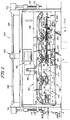
Fig. 2 illustrates a top plan view of the apparatus illustrated inFig. 1 ; -
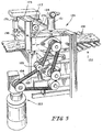
Fig. 3 illustrates an enlarged fragmentary sectional view of a detail of the apparatus illustrated inFigs. 1-2 , taken generally along section lines 3-3 ofFig. 2 ; -
Fig. 4 illustrates an enlarged fragmentary perspective view of a detail of the apparatus illustrated inFigs. 1-2 ; -
Fig. 5 illustrates an enlarged fragmentary perspective view of a detail of the apparatus illustrated inFigs. 1 ,2 and4 ; -
Fig. 6 illustrates a highly simplified diagrammatic top plan view of the detail illustrated inFig. 5 , illustrating certain aspects of its operation; -
Fig. 7 illustrates a fragmentary side elevational view of certain details of the apparatus illustrated inFigs. 1 ,2 ,4 and6 , taken generally along section lines 7-7 ofFigs. 2 and6 ; -
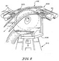
Fig. 8 illustrates a fragmentary, somewhat diagrammatic perspective view of certain details of the apparatus illustrated inFigs. 1 ,2 ,4 and6 , taken generally along section lines 8-8 ofFig. 6 ; -
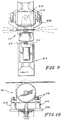
Fig. 9 illustrates a fragmentary, somewhat diagrammatic top plan view of certain details of the apparatus illustrated inFigs. 1 ,2 ,4 and6-8 ; -
Fig. 10 illustrates a fragmentary, somewhat diagrammatic side elevational view of certain details of the apparatus illustrated inFigs. 1 ,2 ,4 and6-9 ; and -
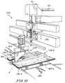
Fig. 11 illustrates an enlarged, somewhat diagrammatic perspective view of certain details of the apparatus illustrated inFigs. 1 ,2 ,4 ,6 and7 . - Referring now to
Figs. 1-3 , a book ofveneer 108 is conveyed along aconveyor 110 through ascanner housing 112, where the book ofveneer 108 is illuminated bylamps 114, which may include fluorescent and ultraviolet (blacklight) lamps, and scanned by imaging devices 116, such as cameras 116-1 and the like, for detecting the wane edge of abook 108, and areas of contrast, such as heartwood, flaws, knots and the like, which it is desired to trim from thebook 108. Imaging devices 116 may include one or more laser detectors 116-2 for detecting, for example, the leading and trailing edges of abook 108, and thus the width of thebook 108, as thebook 108 is conveyed throughhousing 112 onconveyor 110. Once thebook 108 has been scanned by the imaging devices 116, and the width of thebook 108 and locations of the areas of contrast provided via conductors (not shown) to acomputer 118, thecomputer 118 calculates a trimming solution for thebook 108 in an effort to optimize the value of veneer yielded by thebook 108. The inside ofhousing 112 may be finished matte black to reduce internal reflections. Two cameras 116-1 are mounted at each end ofhousing 112. Lasers 116-2 are placed along the centerline ofhousing 112 aboveconveyor 110. Belts ofconveyor 110 convey the book ofveneer 108 acrosshousing 112. According to the invention in the illustrated system, the book ofveneer 108 may optionally be manually marked, for example, with fluorescent chalk, by an operator before the book ofveneer 108 entershousing 112. According to the invention if such marking is detected on the book ofveneer 108,computer 118 is programmed so that that marking overrides the optimization solution provided bycomputer 118. - A series of
fetchers 120 are projected by motor(s) 121, such as (a) pneumatic or hydraulic piston-and-cylinder motor(s) or motor-driven ballscrew(s) or the like, mounted to a framework supporting thefetchers 120, toward thebook 108, between the belts ofconveyor 110, and into engagement withbook 108. Thefetchers 120 are then retracted, transferring thebook 108 fromconveyor 110 onto aconveyor 122 which conveys thebook 108 transversely to its direction of motion through thescanner housing 112. Actuation ofconveyor 122 movesbook 108 to aninlet end 124 of atrimmer 126. Trimmer 126 includes anupper conveyor portion 130 and alower conveyor portion 132.Upper conveyor portion 130 andlower conveyor portion 132 are vertically movable relative to one another for reasons which will be explained. Thebook 108 is transferred fromconveyor 122 betweeninlet rollers lower conveyor portions Upper conveyor portion 130, including infeedroller 134 is adjusted vertically upward or downward as necessary to exert sufficient pressure onbook 108 so thatbook 108 is driven by the rotation of the rollers of upper andlower conveyor portions trimmer 126. - First, second, third and fourth
circular saws lower conveyor portion 132. Firstsaw 140 is the most upstream,second saw 142 next, third saw 144 next, andfourth saw 146 is the most downstream in the motion ofbook 108 throughtrimmer 126.Saws book 108 throughtrimmer 126. Additionally, saws 140, 142, 144 and 146 are independently mounted to pivot about vertical axes so that they make angles with the longitudinal extent of thetrimmer 126. - Turning now to certain details of
scanner housing 112, and with reference toFig. 3 ,scanner housing 112 houses multiple banks 114-1, 114-2, 114-3, 114-4 of lamps. The banks oflamps 114 extend lengthwise ofhousing 112 and transversely of the direction of motion of books ofveneer 108 alongconveyor 110. As the books ofveneer 108 are transported onconveyor 110 throughhousing 112, they are illuminated by the banks oflamps 114, and images of the visible physical attributes of books ofveneer 108 are scanned by scanners 116. The images are transmitted electrically to thecomputer 118. The electrical image signals may be digitized at the scanners 116 or by thecomputer 118 and/or its associated peripheral equipment. - Fetchers 120 and their associated drive motor(s) 121 are "smart." That is, their motor(s) 121 is (are) controlled in response to the scanned image. Once the
book 108 has been scanned, thefetchers 120 are projected into close proximity to the longitudinal centerline of thebook 108, as determined by the preceding scan, by motor(s) 121. Motors 154, such as pneumatic or hydraulic piston-and-cylinder motors or motor-driven ballscrews or the like, mounted on the remote ends offetchers 120project gripper pads 156 between adjacent belts ofconveyor 110 and into gripping contact with the top andbottom surfaces 158, 160 ofbook 108. Motor(s) 121 is (are) then actuated in the opposite direction to transfer the thus-grippedbook 108 fromconveyor 110 toconveyor 122 with the centerline of thebook 108 lying on the centerline ofconveyor 122. Motor(s) 121 may include linear positioners of any of several known types, or the like. Motors 154 are then actuated to release the top andbottom surfaces 158, 160, andbook 108 is conveyed alongconveyor 122 to theinlet end 124 oftrimmer 126. - Referring now particularly to
Figs. 4-6 , infeedrollers bottom surfaces 158, 160 ofbook 108 to transferbook 108 fromconveyor 122 between the upper andlower conveyor portions trimmer 126.Rollers transmission 162 and timing belt 164 so that the top andbottom surfaces 158, 160 are driven forward intotrimmer 126 at the same speed. This helps to maintain the integrity of thebook 108. Theupper roller 134 is in a vertically movable frame driven downward by (a) motor(s) 161, for example, (a) piston and cylinder fluid motor(s). Anothermotor 163, for example, a piston and cylinder fluid motor, drives anidler 165 about which belt 164 is trained to take up the tension in belt 164 asupper roller 134 is raised and lowered. An LVDT 179 measures the spacing betweeninfeed rollers transmission 166. - Referring now particularly to
Figs. 1 ,4 and7 , the upper andlower conveyor portions transmission 166 which turns across shaft 168.Right angle gearboxes 170 are coupled to the remote ends ofcross shaft 168.Lower conveyor portion 132, motor andtransmission 166,shaft 168 andgearboxes 170 are mounted on a supportingframe 172.Ballscrews 174 at the outputs ofgearboxes 170 engagefollowers 176 provided on the supportingframe 178 ofupper conveyor portion 130. The motor andtransmission 166 is assisted bymotors 180, for example, pneumatic or hydraulic piston and cylinder motors, working between the four corners of supportingframe 172 and respective corners of supportingframe 178.Cross shafts 173 are also provided onupper conveyor portion 132 at theinlet 124 andoutlet 206 ends oftrimmer 126. Eachcross shaft 173 has apinion gear 175 mounted at each of its ends. The pinion gears 175 engagerespective racks 177 onlower conveyor portion 130 to assist in maintaining upper andlower conveyor sections LVDT 179 and the positions of motor andtransmission 166 andmotors 180 establishes and maintains a suitable spacing between therollers 181 supported inupper conveyor portion 130 and therollers 181 supported inlower conveyor portion 132 to maintain the integrity ofbook 108 asbook 108 is being conveyed throughtrimmer 126 and trimmed. - Referring particularly to
Fig. 7 , theindividual rollers 181 of the upper andlower conveyor portions transmission 182 which drives abelt 184 trained aboutdrive wheels 186 of therollers 181 ofupper conveyor portion 130 and a motor andtransmission 188 which drives abelt 190 trained aboutdrive wheels 192 of therollers 181 oflower conveyor portion 132. The speeds of motor/transmission assemblies transmission assemblies transmission assembly - Turning now to
Figs. 4 ,6 and8-11 , the mostupstream saw 140 is generally oriented toward the left hand side of thetrimmer 126 facing in the downstream direction in order to facilitate trimming of the left hand side of thebook 108. The second mostupstream saw 142 is generally oriented toward the right hand side of thetrimmer 126 facing in the downstream direction in order to facilitate trimming of the right hand side of thebook 108. The third mostupstream saw 144 is generally oriented somewhat to the right of the center of a book ofveneer 108 as thebook 108 passes through thetrimmer 126. The fourth most upstream saw 146 (the most downstream saw 146) is generally oriented somewhat to the left of the center of a book ofveneer 108 as thebook 108 passes through thetrimmer 126. - Referring now particularly to
Figs. 7 and8 ,waste gates saws gates plates 203 of, for example, polished stainless steel.Plates 203 extend across the conveyor 132 a distance greater that the widest width ofbook 108 which will be trimmed, and the full lengths, upstream to downstream, of the bays withintrimmer 126 in which saws 140 and 142 are located. Anytrimmings 201 from the right and left hand edges of thebook 108 are directed by therespective gates trimmer 126, for conveyance to, for example, a boiler, incinerator, or the like. - Referring now particularly to
Fig. 11 , a selectivelymovable waste gate 204 at thedownstream end 206 oftrimmer 126 handles waste removed from between the right and left margins of thebook 108 bysaws book 108 will be divided longitudinally into three narrower regions 108-1, 108-2 and 108-3, none of which will be diverted bywaste gate 204. This occurs, for example, in the preparation of wood veneers where heartwood and sapwood are separated because of a difference in color, because they are more marketable when they are offered separately. In such events, thewaste gate 204 will not be lowered into interfering relationship with the flow of the middle cut 108-2 ofbook 108 from thedownstream end 206 oftrimmer 126. - However, if
saws book 108, and the removed central section 108-2 is to be diverted to waste,waste gate 204 is actuated downward into interfering relationship with the flow of the thus excised central region 108-2 from thedownstream end 206 oftrimmer 126 and support plates 207-1, 207-2 are separated by (an) appropriate motor(s) 209, and the central region 108-2 is deflected by thewaste gate 204 downward through the opening between support plates 207-1, 207-2 onto awaste conveyor 205. - Referring now particularly to
Figs. 6 and8-10 , thesaws book 108 throughtrimmer 126. In this manner,trimmer 126 can accommodate books of different widths, and can divide these widths as determined by the trimming solution. For example, each saw 140, 142, 144, 146support mechanism 208 andplates 203 can be mounted on alateral traversing mechanism 210, for example, one of the general type available from Nadella GmbH, Trankestrasse 7, 70597 Stuttgart, Germany. - The
saw support mechanism 208 is pivotally mounted from thelateral traversing mechanism 210 to permit thesaw range 0° ≤ α ≤ 3° in either direction in accordance with the trimming solution to aid in optimizing the amount of merchantable veneer which book 108 will yield. If thesaw book 108 of veneer is conveyed past so that thebook 108 of veneer remains longitudinally more or less centered widthwise of thetrimmer 126. Angling of thesaws arcuate rack 212 on eachsupport mechanism 208 and pivotally 214 coupling eachsupport mechanism 208 to itsrespective traversing mechanism 210. A motor drivenpinion 213 engages eachrack 212 to drive therespective rack 212 to effect the trimming solution. The respective saw'smotor 216 is mounted by one ormore motors 218, for example, piston and cylinder fluid motors, on therespective support mechanism 208.Motors 218 project theirrespective saw books 108, all according to the trimming solution.
Claims (16)
- Method for scanning at least one sheet of wood veneer (108), the method being performed in an apparatus including a first conveyor (110), and a scanner housing (112), the method comprising
by a radiation source (114-1,114-2,114-3,114-4) irradiating the at least one sheet of veneer (108),
by a scanning device (116) detecting a feature which it is desired to trim from the at least one sheet of veneer (108), and
by a control system (118) receiving information related to the thus detected feature, the control system (118) further calculating a trimming solution based upon the information,
characterized in that the at least one sheet of veneer (108) may optionally be manually marked by an operator before the at least one sheet of veneer (108) enters the housing, and in that
the control system is programmed so that if the scanning device (116) detects such marking on the at least one sheet of veneer the marking overrides the trimming solution already provided by the control system. - The method of claim 1 wherein the scanning device (116) further includes at least one detector for detecting at least one edge of the at least one sheet of veneer (108).
- The method of claim 2 wherein the at least one detector comprises at least one detector for detecting two edges of the at least one sheet of veneer (108), and the control system (118) receives information related to the thus detected edges and determines the width of the at least one sheet of veneer (108), as the at least one sheet of veneer (108) is conveyed through the housing (112).
- The method of claim 1 to 3, further comprising trimming the edges of sheets (108), the trimming the edges of sheets (108) including conveying the sheets past a first saw (140) for trimming a first side edge of the sheets (108), and then past a second saw (142) for trimming a second side edge of the sheets (108).
- The method of claim 4 wherein at least one of the first (140) and second (142) saws is adjustable to cut at a non-zero angle to a longitudinal extent of the second conveyor (130, 132).
- The method of claim 4 further including conveying the sheets (108) past the third saw (144) for splitting the sheets (108) between the first and second side edges.
- The method of claim 6 conveying the sheets (108) past third (144) and fourth (146) saws for removing a portion (180-2) of the sheets (108) between the first and second side edges.
- The method of claim 4 to 7 wherein the saws (140, 142, 144,146) include motors (210) for adjusting the positions of the saws (140, 142, 144, 146) generally transversely of the second conveyor (130, 132).
- The method of claim 4 to 8 further including automatically positioning the saws (140, 142, 144, 146).
- The method of claim 4 to 9 further including automatically positioning the saws (140, 142, 144, 146) generally transversely of the second conveyor (130, 132).
- The method of claim 4 to 10 comprising conveying stacked sheets (108).
- Apparatus for scanning at least one sheet of wood veneer (103),
the apparatus including a first conveyor (110),
a scanner housing (112),
a radiation source (114-1, 114-2, 114-3, 114-4) for irradiating the at least one sheet of veneer (102),
a scanning device (116) for detecting a feature which it is desired to trim from the at least one sheet of veneer (108),
and a control system (118) for receiving information related to the thus detected feature, the control system (118) is configured to calculate a trimming solution based upon the information, characterized in that
the at least one sheet of veneer (108) may optionally be manually marked by an operator before the at least one sheet of veneer (108) enters the housing, and in that the control system is configured to and is programmed so that if the scanning device (116) detects such marking on the at least one sheet of veneer the marking overrides the trimming solution already provided by the control system. - The apparatus of claim 12, further comprising apparatus (140, 142) for trimming the edges of sheets, the apparatus for trimming the edges of sheets (108) including a second conveyor (130, 132) for conveying the sheets past a first saw (140) for trimming a first side edge of the sheets (108), and then past a second saw (142) for trimming a second side edge of the sheets (108).
- The apparatus of claim 13 further including at least a third saw (144), the second conveyor (130, 132) conveying the sheets (108) past the third saw (144) for splitting the sheets (108) between the first and second side edges.
- The apparatus of claim 14 wherein the at least third saw (144) comprises third (144) and fourth (146) saws, the second conveyor (130, 132) conveying the sheets (108) past the third (144) and fourth (146) saws for removing a portion (108-2) of the sheets (108) between the first and second side edges.
- The apparatus of claims 14 to 15 wherein the saws (140, 142, 144, 146) include motors (210) for adjusting the positions of the saws (140, 142,144, 146) generally transversely of the second conveyor (130, 132).
Priority Applications (1)
| Application Number | Priority Date | Filing Date | Title |
|---|---|---|---|
| PL12163938T PL2476498T3 (en) | 2006-06-20 | 2007-01-22 | Automatic clipping line |
Applications Claiming Priority (2)
| Application Number | Priority Date | Filing Date | Title |
|---|---|---|---|
| US11/471,250 US9050735B2 (en) | 2006-06-20 | 2006-06-20 | Automatic clipping line |
| EP07749112.4A EP2029331B1 (en) | 2006-06-20 | 2007-01-22 | Automatic clipping line |
Related Parent Applications (3)
| Application Number | Title | Priority Date | Filing Date |
|---|---|---|---|
| EP07749112.4 Division | 2007-01-22 | ||
| EP07749112.4A Division EP2029331B1 (en) | 2006-06-20 | 2007-01-22 | Automatic clipping line |
| EP07749112.4A Division-Into EP2029331B1 (en) | 2006-06-20 | 2007-01-22 | Automatic clipping line |
Publications (2)
| Publication Number | Publication Date |
|---|---|
| EP2476498A1 EP2476498A1 (en) | 2012-07-18 |
| EP2476498B1 true EP2476498B1 (en) | 2016-08-10 |
Family
ID=38833895
Family Applications (2)
| Application Number | Title | Priority Date | Filing Date |
|---|---|---|---|
| EP07749112.4A Not-in-force EP2029331B1 (en) | 2006-06-20 | 2007-01-22 | Automatic clipping line |
| EP12163938.9A Not-in-force EP2476498B1 (en) | 2006-06-20 | 2007-01-22 | Automatic clipping line |
Family Applications Before (1)
| Application Number | Title | Priority Date | Filing Date |
|---|---|---|---|
| EP07749112.4A Not-in-force EP2029331B1 (en) | 2006-06-20 | 2007-01-22 | Automatic clipping line |
Country Status (6)
| Country | Link |
|---|---|
| US (2) | US9050735B2 (en) |
| EP (2) | EP2029331B1 (en) |
| JP (1) | JP2009541090A (en) |
| CA (1) | CA2652861A1 (en) |
| PL (1) | PL2476498T3 (en) |
| WO (1) | WO2007149131A2 (en) |
Families Citing this family (20)
| Publication number | Priority date | Publication date | Assignee | Title |
|---|---|---|---|---|
| US9050735B2 (en) * | 2006-06-20 | 2015-06-09 | Danzer Services Schweiz Ag | Automatic clipping line |
| JP2011513098A (en) * | 2008-03-11 | 2011-04-28 | パダナ アーゲー | Apparatus and method for cross cutting and binding of veneer bundles |
| US20100002415A1 (en) * | 2008-07-01 | 2010-01-07 | Munn Jennifer R | Machine with uv illumination |
| DE102008032160B9 (en) * | 2008-07-08 | 2010-09-23 | Holzma Plattenaufteiltechnik Gmbh | Method for splitting plate-shaped workpieces, as well as panel splitter |
| CN103538113B (en) * | 2012-12-07 | 2015-01-07 | 曹守海 | Full-automatic numerical control panel edge trimming saw |
| EE05744B1 (en) * | 2013-06-07 | 2015-04-15 | Bole Oü | Method for producing a laminate floorboards with edges following natural curvature of the wooden material |
| DE102013108485B4 (en) * | 2013-08-06 | 2015-06-25 | Khs Gmbh | Device and method for error tracking in strip materials |
| DE102014204695A1 (en) * | 2014-03-13 | 2015-09-17 | Holzma Plattenaufteiltechnik Gmbh | Method for operating a plate processing plant |
| US20170167986A1 (en) * | 2014-04-25 | 2017-06-15 | Gdt, Inc. | Cosmetic Evaluation Box for Used Electronics |
| CN104999520A (en) * | 2015-06-26 | 2015-10-28 | 淮南市巨惠工贸有限公司 | Intelligent selecting device of three-dimensional view |
| EP4712009A3 (en) | 2016-03-07 | 2026-05-06 | Assurant, Inc. | Screen damage detection for devices |
| PL3254792T3 (en) * | 2016-06-10 | 2019-10-31 | Upm Plywood Oy | A method for sawing edges of a wood laminate panel and an arrangement for the same |
| CA3151157A1 (en) | 2019-09-16 | 2021-03-25 | Stuart Saunders | System, method, apparatus, and computer program product for utilizing machine learning to process an image of a mobile device to determine a mobile device integrity status |
| US11580627B2 (en) | 2020-01-06 | 2023-02-14 | Assurant, Inc. | Systems and methods for automatically grading pre-owned electronic devices |
| CN111452143A (en) * | 2020-05-25 | 2020-07-28 | 龙泉市餐餐乐竹木制品有限公司 | Full-automatic trimming and chamfering all-in-one machine for bamboo and wood board processing |
| CN112140254B (en) * | 2020-09-23 | 2021-05-14 | 湖南宏森新材料科技有限责任公司 | Device for aligning and gluing wood boards |
| CN112405707B (en) * | 2020-11-20 | 2022-06-07 | 吴光云 | Wood system building blocks edge chamfer device |
| CN112677258B (en) * | 2020-12-17 | 2022-04-01 | 南通跃通数控设备股份有限公司 | Continuous lengthening and sizing saw cutting device and method for strip wood |
| CN113043392B (en) * | 2021-04-13 | 2022-05-10 | 山东亿森美居新材料科技有限公司 | Floor processing system and floor processing method |
| CN113182599A (en) * | 2021-04-30 | 2021-07-30 | 天津龙创恒盛实业有限公司 | Equipment for automatically calculating end distance and truncation length of linear guide rail |
Citations (2)
| Publication number | Priority date | Publication date | Assignee | Title |
|---|---|---|---|---|
| US4596172A (en) * | 1983-04-29 | 1986-06-24 | Oliver Machinery Company | Lumber cutting saw |
| US20030192412A1 (en) * | 2002-04-10 | 2003-10-16 | Siempelkamp Handling Systeme Gmbh & Co. | Device for marking and analyzing defects in a system for cutting boards to size made of wood at least in part |
Family Cites Families (87)
| Publication number | Priority date | Publication date | Assignee | Title |
|---|---|---|---|---|
| US176892A (en) * | 1876-05-02 | Improvement in machines for making wood gutters | ||
| US619541A (en) * | 1899-02-14 | S peters co | ||
| US386035A (en) * | 1888-07-10 | riegel | ||
| US1601610A (en) * | 1924-08-20 | 1926-09-28 | Charles K Carter | Motor-driven woodworking tool |
| US1795953A (en) * | 1930-02-14 | 1931-03-10 | Arthur B Johnson | Lap-joint-forming machine |
| US1959667A (en) * | 1932-08-08 | 1934-05-22 | Edwin J Grant | Control device |
| US2332654A (en) * | 1942-06-08 | 1943-10-26 | Pacific Lumber Co | Automatic length-selecting cutoff saw |
| US2501299A (en) * | 1944-10-05 | 1950-03-21 | William G Anderson | Panel trimming machine |
| US3165961A (en) | 1962-11-30 | 1965-01-19 | Weyerhaeuser Co | Apparatus for automatically cutting defective veneer sheets |
| US3318347A (en) * | 1963-06-19 | 1967-05-09 | Turner Machinery Co Inc | Method and apparatus for multiple resawing |
| DE1528152A1 (en) * | 1966-01-11 | 1971-01-14 | Weyerhaeuser Co | Machine for trimming stacks of veneer |
| US3380494A (en) * | 1966-04-15 | 1968-04-30 | George L. Mayo | Wood component member cutting apparatus |
| US3650307A (en) * | 1967-04-12 | 1972-03-21 | Donald L Johnson | Apparatus for primary breakdown of roundwood |
| US3545504A (en) * | 1968-12-13 | 1970-12-08 | Arthur M Ferrari | Multiple band saw |
| US3760667A (en) | 1969-01-15 | 1973-09-25 | Black Clawson Co | Veneer defect detector and clipper control |
| US3710836A (en) * | 1970-12-28 | 1973-01-16 | B Busch | Barrel stave edge sawing machine |
| AR206041A1 (en) * | 1974-07-30 | 1976-06-23 | Acme Timber Ind Ltd | METHOD FOR PRODUCING BOARDS ON BOARDS AND OTHER WOODS CUT TO SAW FROM A WORKPIECE OF THE TYPE OF WOOD AND THE SIMILAR AND AN APPARATUS TO CARRY OUT THE METHOD |
| DE7439738U (en) * | 1974-11-29 | 1975-04-17 | Meyer F & Schwabedissen | Saw, in particular panel dividing saw with scoring and main saw |
| AU514480B2 (en) * | 1976-02-26 | 1981-02-12 | Alcan Research And Development Limited | Sawing apparatus |
| US4098310A (en) * | 1977-03-14 | 1978-07-04 | Arthur Carol Sanford | Apparatus for beveling truss components |
| FI54772C (en) * | 1977-09-27 | 1979-03-12 | Ahlstroem Oy | FOERFARANDE OCH ANORDNING FOER KANTNING AV BRAEDE |
| US4196648A (en) * | 1978-08-07 | 1980-04-08 | Seneca Sawmill Company, Inc. | Automatic sawmill apparatus |
| US4208934A (en) * | 1979-03-20 | 1980-06-24 | Wall Leslie W | Miter saw machine |
| US4239069A (en) * | 1979-08-10 | 1980-12-16 | Zimmerman Edwin H | Automatic cant production machine |
| US4277998A (en) * | 1980-01-16 | 1981-07-14 | Stoddard H. Pyle | Wood member cutting apparatus |
| US4409875A (en) * | 1981-07-20 | 1983-10-18 | Sadahiro Nakajima | Apparatus for manufacturing an integral wooden angle bar |
| JPS5983501U (en) * | 1982-11-29 | 1984-06-06 | 北川精機株式会社 | Plate side edge cutting device |
| SE459239B (en) * | 1983-05-27 | 1989-06-19 | Dutina Hans Ab | PROCEDURE FOR CONTROL OF A CIRCLE SAW SAW SHEET AND DEVICE FOR EXERCISE OF THE PROCEDURE |
| EP0151658A1 (en) * | 1984-02-09 | 1985-08-21 | Carl Rückle Maschinenbau GmbH | Machine for cutting the edges of a stack of veneer sheets, and process carried out by this machine |
| US4815644A (en) * | 1985-01-14 | 1989-03-28 | Armstrong World Industries, Inc. | Apparatus for segmenting building boards |
| JPS6246601A (en) * | 1985-08-26 | 1987-02-28 | 橋本電機工業株式会社 | Cross-peeling device for thin long-sized veneer |
| GB8626649D0 (en) * | 1986-11-07 | 1986-12-10 | Wilson Bros Leeds Ltd | Roof truss component cutter |
| US4712596A (en) * | 1987-02-05 | 1987-12-15 | Mcclaran Tom | Lumber surfacing machine |
| US4823664A (en) * | 1987-07-15 | 1989-04-25 | Cooper Jr Hill M | Tandem sawmill assembly |
| US4954202A (en) * | 1987-11-12 | 1990-09-04 | Industrial Insulations Of Texas, Inc. | Apparatus for making V-groove insulation |
| FI79479C (en) * | 1988-07-15 | 1990-01-10 | Ahlstroem Oy | Circular saw with adjustable blades |
| US4976178A (en) * | 1988-07-28 | 1990-12-11 | Barclay Randel L | Annular scrap segments in tire reduction |
| US4934228A (en) * | 1989-01-13 | 1990-06-19 | U.S. Natural Resources, Inc. | System for diverting veneer sheets having offsize defects |
| US4931113A (en) | 1989-03-09 | 1990-06-05 | Tecton Laminates Corp. | Veneer edge joinder method and apparatus |
| DE3920417A1 (en) * | 1989-06-22 | 1991-01-03 | Bielomatik Leuze & Co | SORTING DEVICE FOR LARGE CUTTINGS |
| US5062340A (en) * | 1990-06-21 | 1991-11-05 | Richard Greven | Cutting and positioning apparatus |
| IT1249595B (en) | 1991-02-12 | 1995-03-09 | Cremona Angelo & Figlio | CUTTING STATION IN SHEETS FOR SHEETS OF WOOD |
| US5134917A (en) * | 1991-04-11 | 1992-08-04 | David Holland | Apparatus and method for making V-groove insulation and tank wrap |
| US5176060A (en) * | 1991-11-18 | 1993-01-05 | Thornton Jack L | Truss miter angle saws |
| US6212983B1 (en) * | 1992-03-04 | 2001-04-10 | Stoddard H. Pyle | Tiltable infeed and outfeed saw table |
| CA2073356A1 (en) * | 1992-07-07 | 1994-01-08 | Hale Randle | Heart centered square timber production mechanism and method |
| US6021701A (en) * | 1994-08-22 | 2000-02-08 | Mckeegan, Jr.; John | System for cutting and finishing muntins |
| JP3010998U (en) * | 1994-11-09 | 1995-05-09 | 廣穎機械工業股▲ふん▼有限公司 | Vertical flipper structure |
| US5943239A (en) * | 1995-03-22 | 1999-08-24 | Alpine Engineered Products, Inc. | Methods and apparatus for orienting power saws in a sawing system |
| IT1285465B1 (en) * | 1996-02-23 | 1998-06-08 | Selco S R L Ora Selco S P A | PANEL SECTIONING MACHINE |
| US6116126A (en) * | 1996-07-10 | 2000-09-12 | Van Den Bulcke; Marc | Method and machine for making profile pieces |
| US5946995A (en) * | 1996-09-09 | 1999-09-07 | Cae Electronics Ltd. Cae Electronique Ltee | Method and apparatus for curve sawing or traverse edging with an active sawbox |
| SE9704212L (en) * | 1996-12-13 | 1998-06-14 | Primwood Ab | Procedure for decomposing logs |
| US5785102A (en) * | 1997-02-20 | 1998-07-28 | Industries P.H.L. Inc. | Board edging infeed apparatus |
| US5816302A (en) * | 1997-04-07 | 1998-10-06 | Newnes Machine Ltd. | Method and apparatus for forming curved cants for curve sawing in an active gangsaw |
| US5950517A (en) * | 1997-05-27 | 1999-09-14 | Yoder; Daniel | Sawmill carriage log turner |
| US6241097B1 (en) * | 1997-08-20 | 2001-06-05 | Walter C. Roman | Bag splitter and separation assembly |
| US6178858B1 (en) * | 1997-09-02 | 2001-01-30 | U.S. Natural Resources, Inc. | Shape sawing system |
| US6202526B1 (en) * | 1997-09-02 | 2001-03-20 | U.S. Natural Resources | Shape sawing machine |
| US6062280A (en) * | 1997-09-24 | 2000-05-16 | Cae Electronics Ltd. Cae Electronique Ltee | Method and apparatus for scanning, optimizing and edging a board with and an active edger |
| CA2251526C (en) * | 1997-11-07 | 2006-12-05 | Terry Raff As Trustee Of The Main Children's Trust | Method for variably controlling work feed rate for cutting wood, metal and other materials |
| US7428858B2 (en) | 1998-04-01 | 2008-09-30 | William M Owens | Feedworks device |
| JP4275773B2 (en) * | 1998-06-16 | 2009-06-10 | 株式会社名南製作所 | Method and apparatus for processing scarf surface of plate-like body |
| ATE305907T1 (en) * | 1998-07-07 | 2005-10-15 | Donnelly Mirrors Ltd | DEVICE FOR BREAKING OFF PRE-SCORED SHAPES OF A GLASS PANEL |
| US6209431B1 (en) * | 1998-10-14 | 2001-04-03 | John L. Wickham | Automated degate and trim machine |
| US6135176A (en) * | 1999-03-10 | 2000-10-24 | Timber Machine Technologies, Inc. | Infeed side chipper drive assembly for pivotable gang saw |
| US6119330A (en) * | 1999-04-21 | 2000-09-19 | Cheng; Chin Chung | Fully automatic cutting metal-working machine |
| US6062281A (en) * | 1999-05-13 | 2000-05-16 | U.S. Natural Resources | Vertical arbor saw for shape sawing a log |
| US6615100B1 (en) * | 1999-07-27 | 2003-09-02 | James Francis Urmson | Automated roof truss component saw |
| US20050120840A1 (en) * | 1999-10-13 | 2005-06-09 | Koskovich Jerome E. | Automated board processing apparatus |
| US6279441B1 (en) * | 2000-02-16 | 2001-08-28 | Nicholson Manufacturing Company | System and apparatus for cutting logs into shorter lengths |
| CA2338242C (en) * | 2000-02-23 | 2004-07-20 | Cae Electronics Ltd. Cae Electronique Ltee | Active sawguide assembly and method |
| CA2309359C (en) * | 2000-04-17 | 2009-07-21 | Cae Mcgehee, Inc. | Log processor and method |
| US6705190B2 (en) * | 2000-07-24 | 2004-03-16 | Coe Newnes Mcgehee Ulc | Lumber trimmer |
| US6526856B2 (en) * | 2000-07-24 | 2003-03-04 | Cae, Inc. | Board trimmer with pre-trimmer near-end saws |
| US6826986B2 (en) * | 2001-05-05 | 2004-12-07 | Ah Beng Lim | Bi-directional singulation system and method |
| US6688197B1 (en) * | 2001-09-24 | 2004-02-10 | Leo L. Niemela | Notch sawing apparatus for dove-tail joints |
| US6826990B2 (en) * | 2002-03-26 | 2004-12-07 | Weyerhaeuser Company | Cutter trimmer sorter |
| US6817392B2 (en) * | 2002-08-28 | 2004-11-16 | Mitek Holdings, Inc. | Apparatus for shaping timbers with improved timber control |
| US7108030B1 (en) * | 2003-05-27 | 2006-09-19 | Timber Machine Technology, Inc. | Lineal optimization gang/edger for cutting cants and flitches |
| CA2434434A1 (en) * | 2003-06-26 | 2004-12-26 | Come Bureau | Curved sawing system following the natural curvature of a tray |
| US7100486B2 (en) * | 2003-07-08 | 2006-09-05 | Leprino Foods Company | Apparatus for dicing a deformable product |
| US20050034786A1 (en) * | 2003-08-12 | 2005-02-17 | Dargan Samuel G. | Radial sawing method |
| US7258050B2 (en) * | 2004-01-09 | 2007-08-21 | Turb-O-Web International Pty. Limited | Method of cutting segmented-end web |
| CA2479428C (en) * | 2004-08-17 | 2009-07-14 | David S. Fenton | Portable sawmill with bi-directional cutting circular saws |
| US7331267B2 (en) * | 2005-03-31 | 2008-02-19 | Urmson James F | Apparatus and method of cutting a work piece |
| US9050735B2 (en) * | 2006-06-20 | 2015-06-09 | Danzer Services Schweiz Ag | Automatic clipping line |
-
2006
- 2006-06-20 US US11/471,250 patent/US9050735B2/en not_active Expired - Fee Related
-
2007
- 2007-01-22 EP EP07749112.4A patent/EP2029331B1/en not_active Not-in-force
- 2007-01-22 EP EP12163938.9A patent/EP2476498B1/en not_active Not-in-force
- 2007-01-22 CA CA002652861A patent/CA2652861A1/en not_active Abandoned
- 2007-01-22 WO PCT/US2007/001791 patent/WO2007149131A2/en not_active Ceased
- 2007-01-22 PL PL12163938T patent/PL2476498T3/en unknown
- 2007-01-22 JP JP2009516477A patent/JP2009541090A/en active Pending
-
2015
- 2015-05-05 US US14/704,411 patent/US20150231794A1/en not_active Abandoned
Patent Citations (2)
| Publication number | Priority date | Publication date | Assignee | Title |
|---|---|---|---|---|
| US4596172A (en) * | 1983-04-29 | 1986-06-24 | Oliver Machinery Company | Lumber cutting saw |
| US20030192412A1 (en) * | 2002-04-10 | 2003-10-16 | Siempelkamp Handling Systeme Gmbh & Co. | Device for marking and analyzing defects in a system for cutting boards to size made of wood at least in part |
Also Published As
| Publication number | Publication date |
|---|---|
| WO2007149131A2 (en) | 2007-12-27 |
| WO2007149131A3 (en) | 2008-12-04 |
| US20150231794A1 (en) | 2015-08-20 |
| US9050735B2 (en) | 2015-06-09 |
| US20070289673A1 (en) | 2007-12-20 |
| EP2029331B1 (en) | 2014-04-16 |
| PL2476498T3 (en) | 2017-08-31 |
| JP2009541090A (en) | 2009-11-26 |
| EP2029331A2 (en) | 2009-03-04 |
| CA2652861A1 (en) | 2007-12-27 |
| EP2029331A4 (en) | 2009-07-22 |
| EP2476498A1 (en) | 2012-07-18 |
Similar Documents
| Publication | Publication Date | Title |
|---|---|---|
| EP2029331B1 (en) | Automatic clipping line | |
| US11772905B2 (en) | Board turner | |
| US5142955A (en) | Lumber cutter for removing end defects and sawing to desired lengths | |
| US7017632B2 (en) | Position-based integrated motion controlled curve sawing | |
| CA1298760C (en) | Circular saw system for cutting boards to length | |
| US4945797A (en) | Automated multiple rip saw feeding apparatus | |
| US4462443A (en) | Positioning and feeding apparatus for lumber edger including improved clamp means | |
| US3903771A (en) | Apparatus for edging and resawing lumber | |
| US7681610B2 (en) | Optimized planermill system and method | |
| US6173829B1 (en) | Circulating paddle positioning fence with flexible track | |
| US6240821B1 (en) | Dual positioning and orienting saw infeed apparatus | |
| US7419047B2 (en) | Board lumber position fence | |
| US3687269A (en) | Apparatus for edging and resawing lumber | |
| EP0785052A1 (en) | Procedure and apparatus for working a tree trunk by chipping | |
| US5390716A (en) | Device for the slicing production of boards | |
| US4430915A (en) | Lumber sorter and method | |
| US4291601A (en) | Shake resaw feed system | |
| CA1166126A (en) | Positioning and feed system for cants and boards | |
| US4485705A (en) | Apparatus for cutting lumber | |
| BRPI0713747A2 (en) | apparatus and methods for trimming edge edges and for scanning at least one plywood blade | |
| CZ290715B6 (en) | Method of sawing a tree trunk and apparatus for making the same | |
| CA1241593A (en) | Lumber end trimmer | |
| FI65727C (en) | SAETTING OF ORDERING BODKAPNING AV EN AENDDEL PAO ETT BRAEDAEMNE | |
| WO1992018300A1 (en) | Method and plant for processing logs | |
| CA1156912A (en) | Shake resaw feed system |
Legal Events
| Date | Code | Title | Description |
|---|---|---|---|
| PUAI | Public reference made under article 153(3) epc to a published international application that has entered the european phase |
Free format text: ORIGINAL CODE: 0009012 |
|
| 17P | Request for examination filed |
Effective date: 20120412 |
|
| AC | Divisional application: reference to earlier application |
Ref document number: 2029331 Country of ref document: EP Kind code of ref document: P |
|
| AK | Designated contracting states |
Kind code of ref document: A1 Designated state(s): AT BE BG CH CY CZ DE DK EE ES FI FR GB GR HU IE IS IT LI LT LU LV MC NL PL PT RO SE SI SK TR |
|
| RIN1 | Information on inventor provided before grant (corrected) |
Inventor name: RASTATTER, DANIEL, J. Inventor name: TROST, JUERGEN, F. Inventor name: LACROIX, WOLFGANG |
|
| RIN1 | Information on inventor provided before grant (corrected) |
Inventor name: TROST, JUERGEN, F. Inventor name: LACROIX, WOLFGANG Inventor name: RASTATTER, DANIEL, J. |
|
| 17Q | First examination report despatched |
Effective date: 20131016 |
|
| GRAP | Despatch of communication of intention to grant a patent |
Free format text: ORIGINAL CODE: EPIDOSNIGR1 |
|
| INTG | Intention to grant announced |
Effective date: 20160216 |
|
| GRAS | Grant fee paid |
Free format text: ORIGINAL CODE: EPIDOSNIGR3 |
|
| GRAA | (expected) grant |
Free format text: ORIGINAL CODE: 0009210 |
|
| AC | Divisional application: reference to earlier application |
Ref document number: 2029331 Country of ref document: EP Kind code of ref document: P |
|
| AK | Designated contracting states |
Kind code of ref document: B1 Designated state(s): AT BE BG CH CY CZ DE DK EE ES FI FR GB GR HU IE IS IT LI LT LU LV MC NL PL PT RO SE SI SK TR |
|
| REG | Reference to a national code |
Ref country code: GB Ref legal event code: FG4D |
|
| REG | Reference to a national code |
Ref country code: CH Ref legal event code: EP Ref country code: AT Ref legal event code: REF Ref document number: 818530 Country of ref document: AT Kind code of ref document: T Effective date: 20160815 |
|
| REG | Reference to a national code |
Ref country code: IE Ref legal event code: FG4D |
|
| REG | Reference to a national code |
Ref country code: DE Ref legal event code: R096 Ref document number: 602007047447 Country of ref document: DE |
|
| REG | Reference to a national code |
Ref country code: DE Ref legal event code: R081 Ref document number: 602007047447 Country of ref document: DE Owner name: DANZER GMBH, CH Free format text: FORMER OWNER: PADANA AG, BAAR, CH Ref country code: DE Ref legal event code: R082 Ref document number: 602007047447 Country of ref document: DE Representative=s name: PFENNING, MEINIG & PARTNER MBB PATENTANWAELTE, DE |
|
| REG | Reference to a national code |
Ref country code: LT Ref legal event code: MG4D |
|
| REG | Reference to a national code |
Ref country code: NL Ref legal event code: MP Effective date: 20160810 |
|
| REG | Reference to a national code |
Ref country code: AT Ref legal event code: MK05 Ref document number: 818530 Country of ref document: AT Kind code of ref document: T Effective date: 20160810 |
|
| PG25 | Lapsed in a contracting state [announced via postgrant information from national office to epo] |
Ref country code: FI Free format text: LAPSE BECAUSE OF FAILURE TO SUBMIT A TRANSLATION OF THE DESCRIPTION OR TO PAY THE FEE WITHIN THE PRESCRIBED TIME-LIMIT Effective date: 20160810 Ref country code: LT Free format text: LAPSE BECAUSE OF FAILURE TO SUBMIT A TRANSLATION OF THE DESCRIPTION OR TO PAY THE FEE WITHIN THE PRESCRIBED TIME-LIMIT Effective date: 20160810 Ref country code: NL Free format text: LAPSE BECAUSE OF FAILURE TO SUBMIT A TRANSLATION OF THE DESCRIPTION OR TO PAY THE FEE WITHIN THE PRESCRIBED TIME-LIMIT Effective date: 20160810 Ref country code: IS Free format text: LAPSE BECAUSE OF FAILURE TO SUBMIT A TRANSLATION OF THE DESCRIPTION OR TO PAY THE FEE WITHIN THE PRESCRIBED TIME-LIMIT Effective date: 20161210 |
|
| PG25 | Lapsed in a contracting state [announced via postgrant information from national office to epo] |
Ref country code: AT Free format text: LAPSE BECAUSE OF FAILURE TO SUBMIT A TRANSLATION OF THE DESCRIPTION OR TO PAY THE FEE WITHIN THE PRESCRIBED TIME-LIMIT Effective date: 20160810 Ref country code: ES Free format text: LAPSE BECAUSE OF FAILURE TO SUBMIT A TRANSLATION OF THE DESCRIPTION OR TO PAY THE FEE WITHIN THE PRESCRIBED TIME-LIMIT Effective date: 20160810 Ref country code: LV Free format text: LAPSE BECAUSE OF FAILURE TO SUBMIT A TRANSLATION OF THE DESCRIPTION OR TO PAY THE FEE WITHIN THE PRESCRIBED TIME-LIMIT Effective date: 20160810 Ref country code: SE Free format text: LAPSE BECAUSE OF FAILURE TO SUBMIT A TRANSLATION OF THE DESCRIPTION OR TO PAY THE FEE WITHIN THE PRESCRIBED TIME-LIMIT Effective date: 20160810 Ref country code: PT Free format text: LAPSE BECAUSE OF FAILURE TO SUBMIT A TRANSLATION OF THE DESCRIPTION OR TO PAY THE FEE WITHIN THE PRESCRIBED TIME-LIMIT Effective date: 20161212 Ref country code: GR Free format text: LAPSE BECAUSE OF FAILURE TO SUBMIT A TRANSLATION OF THE DESCRIPTION OR TO PAY THE FEE WITHIN THE PRESCRIBED TIME-LIMIT Effective date: 20161111 |
|
| PG25 | Lapsed in a contracting state [announced via postgrant information from national office to epo] |
Ref country code: EE Free format text: LAPSE BECAUSE OF FAILURE TO SUBMIT A TRANSLATION OF THE DESCRIPTION OR TO PAY THE FEE WITHIN THE PRESCRIBED TIME-LIMIT Effective date: 20160810 Ref country code: RO Free format text: LAPSE BECAUSE OF FAILURE TO SUBMIT A TRANSLATION OF THE DESCRIPTION OR TO PAY THE FEE WITHIN THE PRESCRIBED TIME-LIMIT Effective date: 20160810 |
|
| REG | Reference to a national code |
Ref country code: DE Ref legal event code: R097 Ref document number: 602007047447 Country of ref document: DE |
|
| PG25 | Lapsed in a contracting state [announced via postgrant information from national office to epo] |
Ref country code: DK Free format text: LAPSE BECAUSE OF FAILURE TO SUBMIT A TRANSLATION OF THE DESCRIPTION OR TO PAY THE FEE WITHIN THE PRESCRIBED TIME-LIMIT Effective date: 20160810 Ref country code: BE Free format text: LAPSE BECAUSE OF FAILURE TO SUBMIT A TRANSLATION OF THE DESCRIPTION OR TO PAY THE FEE WITHIN THE PRESCRIBED TIME-LIMIT Effective date: 20160810 Ref country code: SK Free format text: LAPSE BECAUSE OF FAILURE TO SUBMIT A TRANSLATION OF THE DESCRIPTION OR TO PAY THE FEE WITHIN THE PRESCRIBED TIME-LIMIT Effective date: 20160810 Ref country code: CZ Free format text: LAPSE BECAUSE OF FAILURE TO SUBMIT A TRANSLATION OF THE DESCRIPTION OR TO PAY THE FEE WITHIN THE PRESCRIBED TIME-LIMIT Effective date: 20160810 Ref country code: BG Free format text: LAPSE BECAUSE OF FAILURE TO SUBMIT A TRANSLATION OF THE DESCRIPTION OR TO PAY THE FEE WITHIN THE PRESCRIBED TIME-LIMIT Effective date: 20161110 |
|
| PLBE | No opposition filed within time limit |
Free format text: ORIGINAL CODE: 0009261 |
|
| STAA | Information on the status of an ep patent application or granted ep patent |
Free format text: STATUS: NO OPPOSITION FILED WITHIN TIME LIMIT |
|
| 26N | No opposition filed |
Effective date: 20170511 |
|
| PG25 | Lapsed in a contracting state [announced via postgrant information from national office to epo] |
Ref country code: SI Free format text: LAPSE BECAUSE OF FAILURE TO SUBMIT A TRANSLATION OF THE DESCRIPTION OR TO PAY THE FEE WITHIN THE PRESCRIBED TIME-LIMIT Effective date: 20160810 |
|
| REG | Reference to a national code |
Ref country code: CH Ref legal event code: PL |
|
| GBPC | Gb: european patent ceased through non-payment of renewal fee |
Effective date: 20170122 |
|
| PG25 | Lapsed in a contracting state [announced via postgrant information from national office to epo] |
Ref country code: MC Free format text: LAPSE BECAUSE OF FAILURE TO SUBMIT A TRANSLATION OF THE DESCRIPTION OR TO PAY THE FEE WITHIN THE PRESCRIBED TIME-LIMIT Effective date: 20160810 |
|
| REG | Reference to a national code |
Ref country code: FR Ref legal event code: ST Effective date: 20170929 |
|
| PG25 | Lapsed in a contracting state [announced via postgrant information from national office to epo] |
Ref country code: LI Free format text: LAPSE BECAUSE OF NON-PAYMENT OF DUE FEES Effective date: 20170131 Ref country code: FR Free format text: LAPSE BECAUSE OF NON-PAYMENT OF DUE FEES Effective date: 20170131 Ref country code: CH Free format text: LAPSE BECAUSE OF NON-PAYMENT OF DUE FEES Effective date: 20170131 |
|
| REG | Reference to a national code |
Ref country code: IE Ref legal event code: MM4A |
|
| PG25 | Lapsed in a contracting state [announced via postgrant information from national office to epo] |
Ref country code: LU Free format text: LAPSE BECAUSE OF NON-PAYMENT OF DUE FEES Effective date: 20170122 Ref country code: GB Free format text: LAPSE BECAUSE OF NON-PAYMENT OF DUE FEES Effective date: 20170122 |
|
| PG25 | Lapsed in a contracting state [announced via postgrant information from national office to epo] |
Ref country code: IE Free format text: LAPSE BECAUSE OF NON-PAYMENT OF DUE FEES Effective date: 20170122 |
|
| PGFP | Annual fee paid to national office [announced via postgrant information from national office to epo] |
Ref country code: IT Payment date: 20190123 Year of fee payment: 13 Ref country code: PL Payment date: 20190103 Year of fee payment: 13 Ref country code: DE Payment date: 20190129 Year of fee payment: 13 |
|
| PG25 | Lapsed in a contracting state [announced via postgrant information from national office to epo] |
Ref country code: HU Free format text: LAPSE BECAUSE OF FAILURE TO SUBMIT A TRANSLATION OF THE DESCRIPTION OR TO PAY THE FEE WITHIN THE PRESCRIBED TIME-LIMIT; INVALID AB INITIO Effective date: 20070122 |
|
| PG25 | Lapsed in a contracting state [announced via postgrant information from national office to epo] |
Ref country code: CY Free format text: LAPSE BECAUSE OF NON-PAYMENT OF DUE FEES Effective date: 20160810 |
|
| PG25 | Lapsed in a contracting state [announced via postgrant information from national office to epo] |
Ref country code: TR Free format text: LAPSE BECAUSE OF FAILURE TO SUBMIT A TRANSLATION OF THE DESCRIPTION OR TO PAY THE FEE WITHIN THE PRESCRIBED TIME-LIMIT Effective date: 20160810 |
|
| REG | Reference to a national code |
Ref country code: DE Ref legal event code: R119 Ref document number: 602007047447 Country of ref document: DE |
|
| PG25 | Lapsed in a contracting state [announced via postgrant information from national office to epo] |
Ref country code: DE Free format text: LAPSE BECAUSE OF NON-PAYMENT OF DUE FEES Effective date: 20200801 |
|
| PG25 | Lapsed in a contracting state [announced via postgrant information from national office to epo] |
Ref country code: IT Free format text: LAPSE BECAUSE OF NON-PAYMENT OF DUE FEES Effective date: 20200122 |
|
| PG25 | Lapsed in a contracting state [announced via postgrant information from national office to epo] |
Ref country code: PL Free format text: LAPSE BECAUSE OF NON-PAYMENT OF DUE FEES Effective date: 20200122 |