EP2476367A1 - Ophthalmic measurement device - Google Patents
Ophthalmic measurement device Download PDFInfo
- Publication number
- EP2476367A1 EP2476367A1 EP09849206A EP09849206A EP2476367A1 EP 2476367 A1 EP2476367 A1 EP 2476367A1 EP 09849206 A EP09849206 A EP 09849206A EP 09849206 A EP09849206 A EP 09849206A EP 2476367 A1 EP2476367 A1 EP 2476367A1
- Authority
- EP
- European Patent Office
- Prior art keywords
- examinee
- eye
- laser light
- reflection
- light source
- Prior art date
- Legal status (The legal status is an assumption and is not a legal conclusion. Google has not performed a legal analysis and makes no representation as to the accuracy of the status listed.)
- Granted
Links
Images




Classifications
-
- A—HUMAN NECESSITIES
- A61—MEDICAL OR VETERINARY SCIENCE; HYGIENE
- A61B—DIAGNOSIS; SURGERY; IDENTIFICATION
- A61B3/00—Apparatus for testing the eyes; Instruments for examining the eyes
- A61B3/0075—Apparatus for testing the eyes; Instruments for examining the eyes provided with adjusting devices, e.g. operated by control lever
-
- A—HUMAN NECESSITIES
- A61—MEDICAL OR VETERINARY SCIENCE; HYGIENE
- A61B—DIAGNOSIS; SURGERY; IDENTIFICATION
- A61B3/00—Apparatus for testing the eyes; Instruments for examining the eyes
- A61B3/10—Objective types, i.e. instruments for examining the eyes independent of the patients' perceptions or reactions
- A61B3/14—Arrangements specially adapted for eye photography
- A61B3/15—Arrangements specially adapted for eye photography with means for aligning, spacing or blocking spurious reflection ; with means for relaxing
- A61B3/152—Arrangements specially adapted for eye photography with means for aligning, spacing or blocking spurious reflection ; with means for relaxing for aligning
Definitions
- the present invention relates to an ophthalmic measurement device that measures optical characteristics of an anterior segment of an eye of an examinee, e.g., to enable to quantify a protein concentration or the like in aqueous humor of the examinee's eye. More specifically, the present invention relates to an ophthalmic measurement device that is improved in a positional adjustment (alignment) between the examinee' s eye and the measurement device.
- a protein concentration (flare) and a cell number density in an anterior chamber of an eye reflect conditions of various disorders including a postoperative inflammation. Quantitative measurement of these is of clinical importance.
- a method for measuring them quantitatively a method of irradiating an anterior ocular segment of an examinee with a laser light beam from a laser light source, receiving at a light receiving unit scattered light of the laser light beam from the anterior ocular segment, converting it into an electric signal, and deriving optical characteristics of the anterior ocular segment from this electric signal.
- an ophthalmic measurement device provided with a monitor photographing unit, receiving at the monitor photographing unit a virtual image of scattered light of a laser light beam emitted to an examinee's eye by a surface of a cornea, and the scattered light of the laser light beam, and carrying out a positional adjustment (alignment) between a laser light source and the photographing unit in accordance with positions of the virtual image and the scattered light at the monitor photographing unit (for example, refer to Patent Literature 1).
- an ophthalmic measurement device carrying out alignment with reference to a corneal apex which is different from optical compositions of a light projecting system and a light receiving system.
- an intersecting point of optical axes of the light projecting system and the light receiving system in an examinee' s eye is set as a biologic characteristic measuring point in the examinee's eye displaced as much as a predetermined distance from the corneal apex (for example, refer to Patent Literature 2).
- an ophthalmic measurement device integrally provided at a measuring unit with a semiconductor laser irradiating an anterior ocular segment of an examinee's eye with a laser light beam at an angle of 30°, a high-sensitivity light receiving device receiving scattered light of a laser light beam having an angle of 60° and converting it into an electric signal, a calculating unit calculating optical characteristics of the anterior ocular segment from the electric signal, an infrared LED irradiating the examinee's eye with light from a front, a CCD photographing the examinee's eye from the front, an infrared LED irradiating the examinee's eye with light approximately at an angle of 30°, and a CCD photographing the examinee's eye at an angle of 60°.
- a base is moved to adjust positional relationship between the examinee' s eye and the measuring unit (for example, refer to Patent Literature 2).
- a positional adjustment (alignment) between the laser light source and the light receiving unit and the examinee's eye is important for accurate measurement of the anterior ocular segment.
- the aforementioned respective measurement devices have problems in the aforementioned accurate alignment.
- some of the aforementioned ophthalmic measurement devices have difficulty in increasing the accuracy of the alignment since only the reflection light at the corneal apex is referred to, and others possibly give the examinee a sense of anxiety since a position irradiated with the laser light cannot be checked.
- positional relationship between an examiner and the examinee differs from how the observed examinee's eye looks, which makes it difficult to operate the alignment in some cases.
- alignment operations are complicated, which makes it difficult to shorten alignment time.
- the present invention is accomplished by taking such problems of the conventional techniques as mentioned above into consideration thereof, and an object thereof is to provide a technique that makes it possible to carry out a positional adjustment (alignment) between an examinee' s eye and a measurement device, more accurately or more simply, in an ophthalmic measurement device measuring optical characteristics of an anterior ocular segment of an eye of an examinee.
- an adjustment of positional relationship between the examinee's eye and a measurement device is carried out by utilizing reflection lights, i.e., light generated by reflection of light from a reference light source irradiating the examinee's eye with light from a front at a cornea of the examinee' s eye, light generated by reflection of laser light from a laser light source irradiating the examinee's eye with light obliquely at the cornea of the examinee's eye, and light generated by reflection of the laser light at a crystalline lens of the examinee's eye.
- an ophthalmic measurement device measuring optical characteristics of an anterior ocular segment of an examinee's eye comprising a laser light source irradiating the anterior ocular segment of the examinee's eye with a laser light beam from an oblique direction to the examinee's eye, a light receiving unit receiving scattered light of the laser light beam scattered at the anterior ocular segment and converting the scattered light into an electric signal, and a calculating unit calculating the optical characteristics of the anterior ocular segment from the electric signal further comprises a reference light source irradiating the examinee's eye with light from a front of the examinee's eye, a photographing means photographing the examinee's eye, and a positional adjusting means adjusting relative positions of an optical system including the laser light source, the light receiving unit, the reference light source, and the photographing means and the examinee's eye, and in adjustment of relative positions of the examinee's eye and the optical system by the positional adjusting means, the relative positions are adjusted by utilizing first reflection light generated
- a positional adjustment between the examinee's eye and the measurement device can be carried out with reference to three kinds of reflection light, i.e., reflection light generated by reflection of irradiated light from the reference light source at the cornea of the examinee' s eye, reflection light generated by reflection of irradiated light from the laser light source at the cornea of the examinee's eye, and reflection light generated by reflection of the irradiated light at the crystalline lens
- alignment of the ophthalmic measurement device can be carried out more accurately without complicating operations.
- the ophthalmic measurement device further comprises a displaying unit for displaying an image photographed by the photographing means, and in adjustment of relative positions of the optical system and the examinee' s eye by the positional adjusting means, the relative positions may be adjusted by approximating to respectively set target positions, on the image photographed by the photographing means and displayed on the displaying unit, a position of a first bright point corresponding to a virtual image of the reference light source based on the first reflection light generated by reflection of light emitted from the reference light source at the cornea of the examinee' s eye, a position of a second bright point corresponding to the second reflection light generated by reflection of laser light emitted from the laser light source at the cornea of the examinee's eye, and a position of a third bright point corresponding to the third reflection light generated by reflection of laser light emitted from the laser light source at the crystalline lens of the examinee's eye.
- alignment of the ophthalmic measurement device can be carried out by simple operations of approximating to the target positions three bright point positions appearing on the displaying unit by the reflection light generated by reflection of irradiated light from the reference light source at the cornea of the examinee' s eye and the reflection light generated by reflection of irradiated light from the laser light source at the cornea and the crystalline lens of the examinee's eye.
- alignment can be carried out more simply and more accurately.
- a troublesome operation such as display switching is not needed.
- At least a target representing a target position of the first bright point may be displayed on the displaying unit.
- light emitted from the reference light source may have a wavelength in an infrared region.
- intensity of laser light emitted from the laser light source at the time of adjustment of the relative positions of the examinee's eye and the measurement device (the measurement optical system) may be lower than intensity of laser light emitted from the laser light source at the time of measurement of the optical characteristics of the examinee's eye.
- intensity of light from the reference light source and intensity of light from the laser light source can be close to each other, the bright points can look alike at the time of adjusting positions of the bright points on one displaying unit, and alignment operations can be carried out more readily.
- burden on the examinee's eye can be reduced.
- the photographing means may photograph the examinee's eye from a front. Since the examinee and the examiner normally face each other to perform ophthalmic measurement, a direction of positional relationship between the examinee and the examiner and a direction of display of the examinee's eye on the displaying unit can be equal, which enables the examiner to carry out the alignment operations more smoothly.
- the photographing means in the ophthalmic measurement device of the present invention is not particularly limited as long as it is a means that can photograph reflection light (virtual image) of the reference light source at the examinee's eye and can photograph reflection light (real image) of light from the laser light source at the examinee's eye.
- an image sensor such as a CCD image sensor is preferable from the viewpoint of simplicity of the processing of a photographed image and the configuration.
- providing the laser light source, the light receiving unit, the reference light source, and the photographing means so that the mutual relative positions can be fixed is a prerequisite.
- positional displacement of the aforementioned first, second, and third bright points caused by displacement in positional relationship between the photographing means and each light source can be prevented, and reproducibility of alignment can be secured.
- the ophthalmic measurement device of the present invention includes the positional adjusting means relatively adjusting positions of the examinee's eye and the optical system including the laser light source, the light receiving unit, the reference light source, and the photographing means.
- This positional adjusting means may be a means for adjusting a position of the optical system with respect to the examinee's eye or a means for adjusting a position of the examinee or a face of the examinee while fixing a position of the optical system.
- the positional adjusting means is preferably a base that can relatively move the optical system including the laser light source, the light receiving unit, the reference light source, and the photographing means with respect to the examinee's eye from the viewpoint of carrying out accurate alignment with simple operations.
- the ophthalmic measurement device of the present invention includes the displaying unit for displaying an image photographed by the photographing means.
- the displaying unit a normal displaying device for use in displaying images and information can be used.
- the displaying unit preferably displays optimal positions of the first, second, and third bright points as well from the viewpoint of carrying out accurate and highly reproducible alignment.
- the optimal positions of the first, second, and third bright points may be ones derived as theoretical values or ones obtained from an experience or an experiment although they depend on the measurement target and the measurement part. Displays of the aforementioned optimal positions may be marks put on the screen or images displayed in the screen.
- the ophthalmic measurement device of the present invention may further include a recording unit in which light amounts of the reference light source and the laser light source and images of the examinee's eye by the photographing means are recorded.
- a recording unit With such a recording unit, previous alignment information can be utilized for following alignment, which enables accurate and highly reproducible alignment.
- a normal storage device for use in recording information can be used as the recording unit.
- the calculating unit may extract the first, second, and third bright points from an image of the examinee' s eye and record information on positions of the extracted bright points on the image in the recording unit. Extraction of the respective bright points and specification of the positions on the image can be performed by known image processing techniques.
- the ophthalmic measurement device of the present invention may have an inputting means for inputting data in the calculating unit from outside. In this case, the calculating unit can correlate the light amount of the reference light source, the image of the examinee' s eye or the positional information of the first, second, and third bright points, and various data input by the inputting means with one another and can record them in the recording unit.
- the various data input by the inputting means is not particularly limited as long as it identifies the examinee or the examinee's eye. Examples of such data are an identification number of the examinee and right-left display data representing whether the examinee's eye is a right eye or a left eye.
- a commercially available personal computer can be used as part or all of the recording unit, part or all of the calculating unit, and the inputting means.
- the positional adjusting means in a case where the positional adjusting means is a base, information on measurement can be determined by a position of this base.
- the information determined by a position of the base are the right-left display data and information on whether or not the examinee has reached a position to enable alignment. Determination of such information by a position of the base can further facilitate operations of alignment and operations relating to alignment such as input of data.
- the ophthalmic measurement device of the present invention can be used for various kinds of measurement based on optical characteristics of the anterior ocular segment, such as a protein concentration and a cell number density in an anterior chamber of the eye, obtained from scattered light when the examinee's eye is irradiated with a laser light beam.
- An ophthalmic measurement device includes a fixed base 1, a base 2 provided to be movable on the fixed base 1, a measuring unit 3 fixed on the base 2, and a monitor 4 as a displaying unit fixed at the measuring unit 3 , as illustrated in FIG. 1 .
- a communication cable 5 connected to a personal computer and are provided a base position detector (not illustrated in FIG. 1 ) detecting a position of the base 2 and a supporting base (not illustrated) supporting a face of an examinee.
- the base 2 is provided with a joystick 6 to move the base 2 and perform various operations at the time of alignment and a screen switching button 7 used to instruct switching of images displayed on the monitor 4. Operating this joystick 6 enables the base 2 to be moved with respect to the fixed base 1 by actuation of a motor (not illustrated).
- a component that moves the base 2 with respect to the fixed base 1 corresponds to a positional adjusting means in the present embodiment.
- a measuring button 8 At the top of the joystick 6 is provided a measuring button 8.
- a horizontal direction which is a direction perpendicular to a direction of the examinee opposed to the ophthalmic measurement device is referred to as an X direction
- a vertical upper direction is referred to as a Y direction
- a direction of the examinee to a side of the ophthalmic measurement device is referred to as a Z direction, as illustrated in FIG. 1 .
- the measuring unit 3 is provided not only with the monitor 4 but also with four function buttons 9, a not illustrated printer, a discharging port 10 to discharge a printed matter of a measurement result printed by this printer, an alignment and measurement optical system, and an alignment and measurement control system.
- the monitor 4 is fixed on a back surface of the measuring unit 3 facing the examinee, in a reverse direction from the examinee (to be opposed to a side of an examiner) so that the examiner can look at an image in a state of facing the examinee.
- the alignment and measurement optical system includes an infrared LED 11 as a reference light source irradiating an examinee's eye A with light from a front and a CCD 13 as a photographing means photographing the examinee's eye A via a camera lens 12 from the front.
- the optical system also includes an infrared LED 14 irradiating the examinee's eye A with light from an oblique direction (first oblique direction) at 30° to the examinee's eye A and a CCD 18 photographing the examinee's eye A via an objective lens 15, a half mirror 16, and a camera lens 17 from an oblique direction at 60° to the examinee' s eye A on an opposite side to the infrared LED 14.
- the optical system also includes a semiconductor laser 22 as a laser light source irradiating the examinee's eye A with a laser light beam via a collimating lens 19, a turnable galvano mirror 20, and a light projecting lens 21 narrowing down the light beam toward the examinee's eye A from an oblique direction at 30° to the examinee's eye A.
- the optical system also includes a high-sensitivity light receiving device 26 as a light receiving unit receiving scattered light of the laser light beam from the examinee's eye A via the objective lens 15, the half mirror 16, a light receiving lens 23, a shutter 24, and a light receiving mask 25 (hereinafter, the aforementioned alignment and measurement optical system is also referred to as "an optical system of the measuring unit 3").
- the half mirror 16 is a mirror that allows part of light reflected or scattered in an oblique direction at 60° to the examinee's eye A to pass therethrough and part of the light to be reflected toward the light receiving lens 23.
- a perforated mirror may be used instead of the half mirror 16.
- the light receiving lens 23 is a lens that narrows down light reflected at the half mirror 16 toward the light receiving mask 25.
- the high-sensitivity light receiving device 26 as a light receiving unit is a photoelectric converter transmitting an electric signal in accordance with received light.
- the alignment and measurement control system includes a calculating unit 27 connected to the high-sensitivity light receiving device 26 and calculating optical characteristics of an anterior ocular segment from the electric signal from the high-sensitivity light receiving device 26, a switcher 28 as a switching unit connected to the CCDs 13 and 18 and the calculating unit 27 and switching image signals from the CCD 13 to the monitor 4 and those from the CCD 18 to the monitor 4 , in accordance with on/off states of the infrared LEDs 11 and 14, and a main body memory 29 as a recording unit connected to the calculating unit 27.
- To the calculating unit 27 are respectively connected the infrared LEDs 11 and 14, a base position detector 30, and the like in addition to them.
- the switcher 28 is connected to the monitor 4.
- the optical system of the measuring unit 3 is provided with a fixation lamp 31 to fixate a line of sight of the examinee' s eye A.
- the measuring unit 3 is also provided with a printer 32 to print a printed matter to be discharged from the discharging port 10.
- the communication cable 5 is connected to an external personal computer 33.
- an external printer 34 To the personal computer 33 are respectively connected an external printer 34, an external monitor 35, and a keyboard 36 as an inputting means.
- FIG. 4 An overall operating flow in this method is illustrated in FIG. 4 .
- the examiner powers on the measurement device. Also, the examinee puts his/her face on the supporting base. When the base 2 moves beyond a predetermined range (e.g., the base 2 is pulled to a side of the examinee), the movement of the base 2 is detected by the base position detector 30.
- a predetermined range e.g., the base 2 is pulled to a side of the examinee
- the examinee's eye A is irradiated with light from the front by the infrared LED 11 and is photographed from the front by the CCD 13 in this state, and the image is displayed on the monitor 4.
- a virtual image of the light emitted from the infrared LED 11 as a reference light source by a cornea of the examinee's eye A is displayed on the monitor 4 as a first bright point.
- relative positions of the optical system of the measuring unit 3 and the examinee's eye A in the X and Y directions are adjusted. Specifically, the adjustment is carried out so that the position of this first bright point may approach a target displayed on the monitor 4 as a target position.
- the calculating unit 27 determines that the first step of the alignment is started and turns on the infrared LED 11 and the fixation lamp 31. By doing so, the line of sight of the examinee's eye A is fixated, and the anterior ocular segment of the examinee's eye A is irradiated with infrared light. By irradiation of this infrared light, an image photographed by the CCD 13 is displayed on the monitor 4. Also, by turning on the infrared LED 11, the virtual image of the infrared LED 11 as a light source is displayed at the anterior ocular segment of the examinee' s eye A displayed on the monitor 4.
- FIG. 5 An alignment optical system in the present embodiment is illustrated in FIG. 5 .
- reflection light (first reflection light) generated by reflection of the light emitted from the infrared LED 11 at the anterior ocular segment passes through the camera lens 12, and at this time, a lens barrel of the camera lens acts as an aperture stop.
- the infrared LED 11 is used as a light source for displaying the virtual image by the anterior ocular segment on the monitor 4 and referring to it at the time of alignment and is also an illumination for an iris.
- the infrared LED 11 When the infrared LED 11 is turned on, the image of the anterior ocular segment of the examinee's eye A and the virtual image of the infrared LED 11 as the first bright point are displayed on the monitor 4, as described above. Based on the position of this first bright point, positional relationship between the examinee' s eye A and the optical system of the measuring unit 3 is coarsely adjusted. This adjustment is carried out by operating the joystick 6 to cause the base 2 to be moved. Whether or not the coarse adjustment of the positional relationship between the optical system of the measuring unit 3 and the examinee's eye A is successful is determined by whether or not a position of a first bright point B is in the proximity of a target 37 provided on the monitor 4 as illustrated in FIG. 6 .
- a second step relative positions of the optical system of the measuring unit 3 and the examinee's eye A in the Z direction are adjusted.
- the examiner then operates the joystick 6 so that the first bright point may be the smallest in size while maintaining the position of the measuring unit 3 in the X and Y directions to coarsely adjust the relative positions of the optical system of the measuring unit 3 and the examinee's eye A in the Z direction.
- positional relationship between the infrared LED 11 and the semiconductor laser 22 is set in advance so that laser light emitted from the semiconductor laser 22 may be condensed at a measuring point when the first bright point is displayed smallest.
- a third step accurate alignment is carried out with use of laser light emitted from the semiconductor laser 22.
- the examiner presses the measuring button 8.
- the calculating unit 27 turns on the semiconductor laser 22 and the infrared LED 14.
- the semiconductor laser 22 is set to emit light with a smaller amount of light than that at the time of measurement.
- the calculating unit 27 causes the galvano mirror 20 to be turned. This causes the laser irradiation light from the semiconductor laser 22 to scan a predetermined range of the examinee's eye A.
- a background value is measured by the high-sensitivity light receiving device 26. This background value is signal intensity in a state in which laser light is emitted, but in which scanning at a measurement region has not been performed.
- the examiner finely adjusts positional relationship between the examinee' s eye A and the optical system of the measuring unit 3 with use of the joystick 6 so that the first bright point B may be located in the ring-like target 37 and so that the target 37 may be located between the second bright point C and the third bright point D in the horizontal direction (X direction).
- targets 38 and 39 which are optimal positions of the second bright point C and the third bright point D, are displayed on the monitor 4, it is preferable to finely adjust the positional relationship between the examinee's eye A and the optical system of the measuring unit 3 with use of the joystick 6 so that the second bright point C and the third bright point D may be placed on the respective targets 38 and 39.
- pressing a predetermined function button 9 may cause the amounts of light of the respective light sources and the positions of the targets 37, 38, and 39 on the monitor 4 for observation to be determined based on the corresponding data.
- the calculating unit 27 determines whether or not the alignment is favorable from the difference and the height level of the background value depending on the irradiation position of the laser light E, and in a case where the calculating unit 27 determines that the alignment is favorable, the blinking speeds or the display colors of the targets 37, 38, and 39 are changed, for example. This enables the examiner to confirm that the device is in a measurable state.
- the calculating unit 27 stores in the main body memory 29 alignment information such as the light amounts of the infrared LED 11 and the semiconductor laser 22 and the positions of the first bright point B, the second bright point C, and the third bright point D displayed on the monitor 4 at the time of the end of the third step.
- Measurement may be started automatically or manually. Meanwhile, as examples of a mode allowing measurement to be started either automatically or manually, an auto mode, a semi-auto mode, and a manual mode are raised.
- the calculating unit 27 determines that the alignment is sufficiently favorable, measurement is started automatically. In this case, no manual operations such as the measuring button 8 are required. Also, in this case, the measuring button 8 will not function even if the measuring button 8 is pressed by the examiner.
- the examiner In the semi-auto mode, when the calculating unit 27 determines that the alignment is sufficiently favorable, and the examiner presses the measuring button 8, measurement is started. In this case, the examiner can start measurement with reference to signals representing favorability of the alignment such as the blinking speeds or the display colors of the targets on the monitor 4.
- the examiner In the manual mode, regardless of the determination at the calculating unit 27, the examiner refers to the blinking speeds or the display colors of the targets on the monitor 4 representing favorability of the alignment and presses the measuring button 8 at right timing to start measurement. A first round of measurement is performed in either mode.
- the calculating unit 27 displays a measurement window 40 illustrated in FIG. 7 on the monitor 4 via the switcher 28.
- the measurement window 40 represents a light receiving range of the high-sensitivity light receiving device 26 determined by an aperture width of the light receiving mask 25.
- a measurement result is recorded in the main body memory 29, and a measurement result as illustrated in FIG. 8 is displayed on the monitor 4.
- a predetermined function button 9 is pressed in a state in which the measurement result is displayed on the monitor 4
- the measurement result in FIG. 8 is printed by the printer 32, and a printed matter is discharged from the discharging port 10.
- the measuring button 8 is pressed at this time, the procedure returns to the state of the aforementioned fourth step to enable repeated measurement.
- the optical characteristics of the anterior ocular segment of the examinee's eye A are measured several times as needed.
- a screen confirming whether the alignment information at the aforementioned fourth step as well as the measurement result data is to be recorded is displayed on the monitor 4. Whether or not it is recorded is specified by operating a function button 9. In a case where nothing is specified, the aforementioned alignment information is not recorded, and only the measurement result data is recorded in the main body memory 29.
- the measurement result data, data relating to the alignment, and data relating to the examinee and the examinee's eye A are correlated with one another and are recorded in the main body memory 29.
- the aforementioned data relating to the alignment includes light amounts of the infrared LED 11 and the infrared LED 14 recorded at the time of measurement, positions of respective images extracted and obtained by image processing of the first bright point B, the second bright point C, and the third bright point D in an image displayed on the monitor 4 and luminance of the images, and the like.
- the aforementioned data relating to the examinee and the examinee's eye A includes an examinee's ID identifying the individual examinee, data of right or left eye, and the like (refer to FIG. 10 ).
- Data recorded in the main body memory 29 can be transmitted to the personal computer 33 by an operation of a function button 9 and can be recorded in the personal computer 33.
- the present embodiment is configured to adjust relative positions of the optical system of the measuring unit 3 and the examinee's eye A by utilizing the bright point (the first bright point B) corresponding to the virtual image by irradiation of the examinee's eye A with light from the front and the two bright points (the second bright point C and the third bright point D), which are real images by irradiation of the examinee's eye A with laser light from the oblique direction, by light generated by reflection of the light at the cornea of the examinee' s eye A and light generated by reflection of the light at the crystalline lens of the examinee' s eye A.
- positional adjustment is carried out based on the three kinds of information from the two directions, which enables more highly accurate alignment than in a conventional measurement device. Accordingly, at the time of measurement of optical characteristics of the anterior ocular segment of the examinee' s eye A, highly reproducible measurement can be performed.
- the virtual image by irradiation with the light from the front and the real images by the light generated by reflection of the laser light E from the oblique direction at the cornea and the crystalline lens of the examinee's eye A are photographed at the CCD 13 provided at the front of the examinee's eye A and are displayed on the monitor 4.
- the examiner does not need to switch the display screens in the middle of alignment.
- the examiner since the examiner can carry out the alignment with use of the display screen photographed from the front in a state of facing the examinee, the examiner is less likely to lose the sense of direction in the alignment operation. This eliminates inconvenience in the alignment operation caused by a difference between a direction in which the examiner looks and a direction in which the examiner desires to operate, which further facilitates the alignment operation.
- the measurement result, the data relating to the alignment, and the data relating to the examinee's eye A and the examinee are correlated with one another and are recorded in the main body memory 29, alignment conditions and previous measurement results can be read out collectively from the examinee's state, which is further effective in understanding the course of the examinee' s eye A and organizing and utilizing the data.
- the ophthalmic measurement device and the personal computer 33 are connected, the measurement result, the data relating to the alignment, and the like can be taken out of the ophthalmic measurement device.
- the measurement result of the examinee's eye A, the alignment conditions, and the information on the course of the examinee's eye A can be shared among plural examiners.
- accurate measurement of optical characteristics of the anterior ocular segment can be performed by any of the examiners.
- the examinee can undergo the aforementioned accurate measurement by the nearest ophthalmologist, which can enhance the examinee's convenience regarding measurement.
Landscapes
- Life Sciences & Earth Sciences (AREA)
- Health & Medical Sciences (AREA)
- Medical Informatics (AREA)
- Biophysics (AREA)
- Ophthalmology & Optometry (AREA)
- Engineering & Computer Science (AREA)
- Biomedical Technology (AREA)
- Heart & Thoracic Surgery (AREA)
- Physics & Mathematics (AREA)
- Molecular Biology (AREA)
- Surgery (AREA)
- Animal Behavior & Ethology (AREA)
- General Health & Medical Sciences (AREA)
- Public Health (AREA)
- Veterinary Medicine (AREA)
- Eye Examination Apparatus (AREA)
Abstract
Description
- The present invention relates to an ophthalmic measurement device that measures optical characteristics of an anterior segment of an eye of an examinee, e.g., to enable to quantify a protein concentration or the like in aqueous humor of the examinee's eye. More specifically, the present invention relates to an ophthalmic measurement device that is improved in a positional adjustment (alignment) between the examinee' s eye and the measurement device.
- A protein concentration (flare) and a cell number density in an anterior chamber of an eye reflect conditions of various disorders including a postoperative inflammation. Quantitative measurement of these is of clinical importance. As a method for measuring them quantitatively is known a method of irradiating an anterior ocular segment of an examinee with a laser light beam from a laser light source, receiving at a light receiving unit scattered light of the laser light beam from the anterior ocular segment, converting it into an electric signal, and deriving optical characteristics of the anterior ocular segment from this electric signal.
- As a measurement device for use in such a measurement method is known an ophthalmic measurement device provided with a monitor photographing unit, receiving at the monitor photographing unit a virtual image of scattered light of a laser light beam emitted to an examinee's eye by a surface of a cornea, and the scattered light of the laser light beam, and carrying out a positional adjustment (alignment) between a laser light source and the photographing unit in accordance with positions of the virtual image and the scattered light at the monitor photographing unit (for example, refer to Patent Literature 1).
- Also known is an ophthalmic measurement device carrying out alignment with reference to a corneal apex which is different from optical compositions of a light projecting system and a light receiving system. In the alignment, an intersecting point of optical axes of the light projecting system and the light receiving system in an examinee' s eye is set as a biologic characteristic measuring point in the examinee's eye displaced as much as a predetermined distance from the corneal apex (for example, refer to Patent Literature 2).
- Further known is an ophthalmic measurement device integrally provided at a measuring unit with a semiconductor laser irradiating an anterior ocular segment of an examinee's eye with a laser light beam at an angle of 30°, a high-sensitivity light receiving device receiving scattered light of a laser light beam having an angle of 60° and converting it into an electric signal, a calculating unit calculating optical characteristics of the anterior ocular segment from the electric signal, an infrared LED irradiating the examinee's eye with light from a front, a CCD photographing the examinee's eye from the front, an infrared LED irradiating the examinee's eye with light approximately at an angle of 30°, and a CCD photographing the examinee's eye at an angle of 60°. In this device, based on first and second virtual images by the two CCDs, a base is moved to adjust positional relationship between the examinee' s eye and the measuring unit (for example, refer to Patent Literature 2).
- In the aforementioned measurement methods, a positional adjustment (alignment) between the laser light source and the light receiving unit and the examinee's eye is important for accurate measurement of the anterior ocular segment. However, the aforementioned respective measurement devices have problems in the aforementioned accurate alignment.
- For example, some of the aforementioned ophthalmic measurement devices have difficulty in increasing the accuracy of the alignment since only the reflection light at the corneal apex is referred to, and others possibly give the examinee a sense of anxiety since a position irradiated with the laser light cannot be checked. Also, in the device in which the anterior ocular segment of the examinee's eye is observed obliquely to carry out alignment, positional relationship between an examiner and the examinee differs from how the observed examinee's eye looks, which makes it difficult to operate the alignment in some cases. Further, in the device that requires alignment in two steps, there is a case in which alignment operations are complicated, which makes it difficult to shorten alignment time.
-
- Patent Literature 1:
Japanese Patent Application Laid-Open No. S64-17623 - Patent Literature 2:
Japanese Patent Application Laid-Open No. 2004-275503 - Patent Literature 3:
Japanese Patent Application Laid-Open No. 2005-224430 - The present invention is accomplished by taking such problems of the conventional techniques as mentioned above into consideration thereof, and an object thereof is to provide a technique that makes it possible to carry out a positional adjustment (alignment) between an examinee' s eye and a measurement device, more accurately or more simply, in an ophthalmic measurement device measuring optical characteristics of an anterior ocular segment of an eye of an examinee.
- In the present invention, in measuring optical characteristics of an anterior ocular segment of an examinee's eye, an adjustment of positional relationship between the examinee's eye and a measurement device (a measurement optical system) is carried out by utilizing reflection lights, i.e., light generated by reflection of light from a reference light source irradiating the examinee's eye with light from a front at a cornea of the examinee' s eye, light generated by reflection of laser light from a laser light source irradiating the examinee's eye with light obliquely at the cornea of the examinee's eye, and light generated by reflection of the laser light at a crystalline lens of the examinee's eye.
- More specifically, an ophthalmic measurement device measuring optical characteristics of an anterior ocular segment of an examinee's eye comprising a laser light source irradiating the anterior ocular segment of the examinee's eye with a laser light beam from an oblique direction to the examinee's eye, a light receiving unit receiving scattered light of the laser light beam scattered at the anterior ocular segment and converting the scattered light into an electric signal, and a calculating unit calculating the optical characteristics of the anterior ocular segment from the electric signal further comprises a reference light source irradiating the examinee's eye with light from a front of the examinee's eye, a photographing means photographing the examinee's eye, and a positional adjusting means adjusting relative positions of an optical system including the laser light source, the light receiving unit, the reference light source, and the photographing means and the examinee's eye, and in adjustment of relative positions of the examinee's eye and the optical system by the positional adjusting means, the relative positions are adjusted by utilizing first reflection light generated by reflection of light emitted from the reference light source at a cornea of the examinee's eye, second reflection light generated by reflection of laser light emitted from the laser light source at the cornea of the examinee's eye, and third reflection light generated by reflection of laser light emitted from the laser light source at a crystalline lens of the examinee's eye.
- With the present invention, since a positional adjustment between the examinee's eye and the measurement device (the measurement optical system) can be carried out with reference to three kinds of reflection light, i.e., reflection light generated by reflection of irradiated light from the reference light source at the cornea of the examinee' s eye, reflection light generated by reflection of irradiated light from the laser light source at the cornea of the examinee's eye, and reflection light generated by reflection of the irradiated light at the crystalline lens, alignment of the ophthalmic measurement device can be carried out more accurately without complicating operations.
- Also, in the present invention, the ophthalmic measurement device further comprises a displaying unit for displaying an image photographed by the photographing means, and in adjustment of relative positions of the optical system and the examinee' s eye by the positional adjusting means, the relative positions may be adjusted by approximating to respectively set target positions, on the image photographed by the photographing means and displayed on the displaying unit, a position of a first bright point corresponding to a virtual image of the reference light source based on the first reflection light generated by reflection of light emitted from the reference light source at the cornea of the examinee' s eye, a position of a second bright point corresponding to the second reflection light generated by reflection of laser light emitted from the laser light source at the cornea of the examinee's eye, and a position of a third bright point corresponding to the third reflection light generated by reflection of laser light emitted from the laser light source at the crystalline lens of the examinee's eye.
- By doing so, alignment of the ophthalmic measurement device can be carried out by simple operations of approximating to the target positions three bright point positions appearing on the displaying unit by the reflection light generated by reflection of irradiated light from the reference light source at the cornea of the examinee' s eye and the reflection light generated by reflection of irradiated light from the laser light source at the cornea and the crystalline lens of the examinee's eye. Thus, alignment can be carried out more simply and more accurately. Also, at this time, a troublesome operation such as display switching is not needed.
- Also, in the present invention, at least a target representing a target position of the first bright point may be displayed on the displaying unit. By doing so, at least the target position of the first bright point becomes clearer for an examiner, and alignment operations can be carried out more readily and more accurately.
- Also, in the present invention, light emitted from the reference light source may have a wavelength in an infrared region. By doing so, inconvenience in which the examinee feels light from the reference light source too bright can be restricted, and burden on the examinee's eye can be reduced. Also, a clear virtual image can be obtained on the displaying unit as well.
- Also, in the present invention, intensity of laser light emitted from the laser light source at the time of adjustment of the relative positions of the examinee's eye and the measurement device (the measurement optical system) may be lower than intensity of laser light emitted from the laser light source at the time of measurement of the optical characteristics of the examinee's eye. By doing so, intensity of light from the reference light source and intensity of light from the laser light source can be close to each other, the bright points can look alike at the time of adjusting positions of the bright points on one displaying unit, and alignment operations can be carried out more readily. At the same time, burden on the examinee's eye can be reduced.
- Also, in the present invention, the photographing means may photograph the examinee's eye from a front. Since the examinee and the examiner normally face each other to perform ophthalmic measurement, a direction of positional relationship between the examinee and the examiner and a direction of display of the examinee's eye on the displaying unit can be equal, which enables the examiner to carry out the alignment operations more smoothly.
- It is to be noted that the photographing means in the ophthalmic measurement device of the present invention is not particularly limited as long as it is a means that can photograph reflection light (virtual image) of the reference light source at the examinee's eye and can photograph reflection light (real image) of light from the laser light source at the examinee's eye. As the photographing means, an image sensor such as a CCD image sensor is preferable from the viewpoint of simplicity of the processing of a photographed image and the configuration.
- Also, in the present invention, providing the laser light source, the light receiving unit, the reference light source, and the photographing means so that the mutual relative positions can be fixed is a prerequisite. By fixing the relative positions, positional displacement of the aforementioned first, second, and third bright points caused by displacement in positional relationship between the photographing means and each light source can be prevented, and reproducibility of alignment can be secured.
- Also, the ophthalmic measurement device of the present invention includes the positional adjusting means relatively adjusting positions of the examinee's eye and the optical system including the laser light source, the light receiving unit, the reference light source, and the photographing means. This positional adjusting means may be a means for adjusting a position of the optical system with respect to the examinee's eye or a means for adjusting a position of the examinee or a face of the examinee while fixing a position of the optical system. The positional adjusting means is preferably a base that can relatively move the optical system including the laser light source, the light receiving unit, the reference light source, and the photographing means with respect to the examinee's eye from the viewpoint of carrying out accurate alignment with simple operations.
- The ophthalmic measurement device of the present invention includes the displaying unit for displaying an image photographed by the photographing means. As the displaying unit, a normal displaying device for use in displaying images and information can be used. The displaying unit preferably displays optimal positions of the first, second, and third bright points as well from the viewpoint of carrying out accurate and highly reproducible alignment. The optimal positions of the first, second, and third bright points may be ones derived as theoretical values or ones obtained from an experience or an experiment although they depend on the measurement target and the measurement part. Displays of the aforementioned optimal positions may be marks put on the screen or images displayed in the screen.
- The ophthalmic measurement device of the present invention may further include a recording unit in which light amounts of the reference light source and the laser light source and images of the examinee's eye by the photographing means are recorded. With such a recording unit, previous alignment information can be utilized for following alignment, which enables accurate and highly reproducible alignment. As the recording unit, a normal storage device for use in recording information can be used.
- In a case where the ophthalmic measurement device of the present invention has a recording unit, the calculating unit may extract the first, second, and third bright points from an image of the examinee' s eye and record information on positions of the extracted bright points on the image in the recording unit. Extraction of the respective bright points and specification of the positions on the image can be performed by known image processing techniques. Also, in this case, the ophthalmic measurement device of the present invention may have an inputting means for inputting data in the calculating unit from outside. In this case, the calculating unit can correlate the light amount of the reference light source, the image of the examinee' s eye or the positional information of the first, second, and third bright points, and various data input by the inputting means with one another and can record them in the recording unit. Thus, measured data can be organized and utilized for the future easily. The various data input by the inputting means is not particularly limited as long as it identifies the examinee or the examinee's eye. Examples of such data are an identification number of the examinee and right-left display data representing whether the examinee's eye is a right eye or a left eye. As part or all of the recording unit, part or all of the calculating unit, and the inputting means, a commercially available personal computer can be used.
- Also, in the ophthalmic measurement device of the present invention, in a case where the positional adjusting means is a base, information on measurement can be determined by a position of this base. Examples of the information determined by a position of the base are the right-left display data and information on whether or not the examinee has reached a position to enable alignment. Determination of such information by a position of the base can further facilitate operations of alignment and operations relating to alignment such as input of data.
- Also, the ophthalmic measurement device of the present invention can be used for various kinds of measurement based on optical characteristics of the anterior ocular segment, such as a protein concentration and a cell number density in an anterior chamber of the eye, obtained from scattered light when the examinee's eye is irradiated with a laser light beam.
- It is to be noted that the aforementioned solutions to the problems of the present invention can be used in combination with one another as much as possible.
- With the present invention, it is possible to carry out, more accurately or more simply, a positional adjustment (alignment) between an examinee's eye and a measurement device in an ophthalmic measurement device measuring optical characteristics of an anterior ocular segment of an eye of an examinee.
-
-
FIG. 1 illustrates an outline view of a measurement device according to an embodiment of the present invention. -
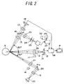
FIG. 2 illustrates a configuration of an optical system in the measurement device according to the present invention. -
FIG. 3 illustrates a configuration of a control system in the measurement device according to the present invention. -
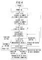
FIG. 4 illustrates an overall flow of measurement by the measurement device according to the present invention. -
FIG. 5 illustrates an optical system to be used at first to third steps in the measurement according to the present invention. -
FIG. 6 illustrates an example of a screen image displayed on a monitor at the first to third steps in the measurement according to the present invention. -
FIG. 7 illustrates an example of a screen image displayed on the monitor at a fourth step in the measurement according to the present invention. -
FIG. 8 illustrates an example of a measurement result displayed at a fifth step in the measurement according to the present invention. -
FIG. 9 illustrates an example of a list of measurement results displayed at a sixth step in the measurement according to the present invention. -
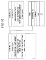
FIG. 10 illustrates an example of data relating to alignment, data relating to an examinee and an examinee's eye, and correlation of these recorded at the sixth step in the measurement according to the present invention. - Hereinafter, embodiments of the present invention will be described with reference to the drawings.
- An ophthalmic measurement device according to the present embodiment includes a fixed
base 1, abase 2 provided to be movable on the fixedbase 1, a measuringunit 3 fixed on thebase 2, and amonitor 4 as a displaying unit fixed at the measuringunit 3 , as illustrated inFIG. 1 . - To the fixed
base 1 is connected acommunication cable 5 connected to a personal computer and are provided a base position detector (not illustrated inFIG. 1 ) detecting a position of thebase 2 and a supporting base (not illustrated) supporting a face of an examinee. Thebase 2 is provided with ajoystick 6 to move thebase 2 and perform various operations at the time of alignment and ascreen switching button 7 used to instruct switching of images displayed on themonitor 4. Operating thisjoystick 6 enables thebase 2 to be moved with respect to the fixedbase 1 by actuation of a motor (not illustrated). A component that moves thebase 2 with respect to the fixedbase 1 corresponds to a positional adjusting means in the present embodiment. At the top of thejoystick 6 is provided ameasuring button 8. It is to be noted that, in the following description, a horizontal direction which is a direction perpendicular to a direction of the examinee opposed to the ophthalmic measurement device is referred to as an X direction, a vertical upper direction is referred to as a Y direction, and a direction of the examinee to a side of the ophthalmic measurement device is referred to as a Z direction, as illustrated inFIG. 1 . - The measuring
unit 3 is provided not only with themonitor 4 but also with fourfunction buttons 9, a not illustrated printer, a dischargingport 10 to discharge a printed matter of a measurement result printed by this printer, an alignment and measurement optical system, and an alignment and measurement control system. Themonitor 4 is fixed on a back surface of the measuringunit 3 facing the examinee, in a reverse direction from the examinee (to be opposed to a side of an examiner) so that the examiner can look at an image in a state of facing the examinee. - As illustrated in
FIG. 2 , the alignment and measurement optical system includes aninfrared LED 11 as a reference light source irradiating an examinee's eye A with light from a front and aCCD 13 as a photographing means photographing the examinee's eye A via acamera lens 12 from the front. The optical system also includes aninfrared LED 14 irradiating the examinee's eye A with light from an oblique direction (first oblique direction) at 30° to the examinee's eye A and aCCD 18 photographing the examinee's eye A via anobjective lens 15, ahalf mirror 16, and acamera lens 17 from an oblique direction at 60° to the examinee' s eye A on an opposite side to theinfrared LED 14. The optical system also includes asemiconductor laser 22 as a laser light source irradiating the examinee's eye A with a laser light beam via acollimating lens 19, aturnable galvano mirror 20, and alight projecting lens 21 narrowing down the light beam toward the examinee's eye A from an oblique direction at 30° to the examinee's eye A. The optical system also includes a high-sensitivitylight receiving device 26 as a light receiving unit receiving scattered light of the laser light beam from the examinee's eye A via theobjective lens 15, thehalf mirror 16, alight receiving lens 23, ashutter 24, anda light receiving mask 25 (hereinafter, the aforementioned alignment and measurement optical system is also referred to as "an optical system of the measuringunit 3"). - The
half mirror 16 is a mirror that allows part of light reflected or scattered in an oblique direction at 60° to the examinee's eye A to pass therethrough and part of the light to be reflected toward thelight receiving lens 23. In the present embodiment, a perforated mirror may be used instead of thehalf mirror 16. Thelight receiving lens 23 is a lens that narrows down light reflected at thehalf mirror 16 toward thelight receiving mask 25. The high-sensitivitylight receiving device 26 as a light receiving unit is a photoelectric converter transmitting an electric signal in accordance with received light. - As illustrated in
FIGS. 2 and3 , the alignment and measurement control system includes a calculatingunit 27 connected to the high-sensitivitylight receiving device 26 and calculating optical characteristics of an anterior ocular segment from the electric signal from the high-sensitivitylight receiving device 26, aswitcher 28 as a switching unit connected to theCCDs unit 27 and switching image signals from theCCD 13 to themonitor 4 and those from theCCD 18 to themonitor 4 , in accordance with on/off states of theinfrared LEDs main body memory 29 as a recording unit connected to the calculatingunit 27. To the calculatingunit 27 are respectively connected theinfrared LEDs base position detector 30, and the like in addition to them. Theswitcher 28 is connected to themonitor 4. - Additionally, the optical system of the measuring
unit 3 is provided with afixation lamp 31 to fixate a line of sight of the examinee' s eye A. The measuringunit 3 is also provided with aprinter 32 to print a printed matter to be discharged from the dischargingport 10. - The
communication cable 5 is connected to an externalpersonal computer 33. To thepersonal computer 33 are respectively connected anexternal printer 34, anexternal monitor 35, and akeyboard 36 as an inputting means. - A method for measuring optical characteristics of the anterior ocular segment by the aforementioned ophthalmic measurement device will be described below. An overall operating flow in this method is illustrated in
FIG. 4 . - First, the examiner powers on the measurement device. Also, the examinee puts his/her face on the supporting base. When the
base 2 moves beyond a predetermined range (e.g., thebase 2 is pulled to a side of the examinee), the movement of thebase 2 is detected by thebase position detector 30. - At a first step, the examinee's eye A is irradiated with light from the front by the
infrared LED 11 and is photographed from the front by theCCD 13 in this state, and the image is displayed on themonitor 4. In the present embodiment, a virtual image of the light emitted from theinfrared LED 11 as a reference light source by a cornea of the examinee's eye A is displayed on themonitor 4 as a first bright point. Subsequently, based on a position of this first bright point, relative positions of the optical system of the measuringunit 3 and the examinee's eye A in the X and Y directions are adjusted. Specifically, the adjustment is carried out so that the position of this first bright point may approach a target displayed on themonitor 4 as a target position. - When it is detected by the
base position detector 30 that thebase 2 moves beyond a predetermined range, the calculatingunit 27 determines that the first step of the alignment is started and turns on theinfrared LED 11 and thefixation lamp 31. By doing so, the line of sight of the examinee's eye A is fixated, and the anterior ocular segment of the examinee's eye A is irradiated with infrared light. By irradiation of this infrared light, an image photographed by theCCD 13 is displayed on themonitor 4. Also, by turning on theinfrared LED 11, the virtual image of theinfrared LED 11 as a light source is displayed at the anterior ocular segment of the examinee' s eye A displayed on themonitor 4. An alignment optical system in the present embodiment is illustrated inFIG. 5 . InFIG. 5 , reflection light (first reflection light) generated by reflection of the light emitted from theinfrared LED 11 at the anterior ocular segment passes through thecamera lens 12, and at this time, a lens barrel of the camera lens acts as an aperture stop. Meanwhile, theinfrared LED 11 is used as a light source for displaying the virtual image by the anterior ocular segment on themonitor 4 and referring to it at the time of alignment and is also an illumination for an iris. - When the
infrared LED 11 is turned on, the image of the anterior ocular segment of the examinee's eye A and the virtual image of theinfrared LED 11 as the first bright point are displayed on themonitor 4, as described above. Based on the position of this first bright point, positional relationship between the examinee' s eye A and the optical system of the measuringunit 3 is coarsely adjusted. This adjustment is carried out by operating thejoystick 6 to cause thebase 2 to be moved. Whether or not the coarse adjustment of the positional relationship between the optical system of the measuringunit 3 and the examinee's eye A is successful is determined by whether or not a position of a first bright point B is in the proximity of atarget 37 provided on themonitor 4 as illustrated inFIG. 6 . When the examiner determines that the positional relationship between the examinee's eye A and the optical system of the measuringunit 3 in the X and Y directions is coarsely adjusted successfully based on the first bright point, a coarse adjustment of positional relationship in the Z direction is then carried out as a second step. - At a second step, relative positions of the optical system of the measuring
unit 3 and the examinee's eye A in the Z direction are adjusted. In a case where it is determined at the first step that the relative positions of the examinee' s eye A and the optical system of the measuringunit 3 in the X and Y directions are coarsely adjusted successfully, the examiner then operates thejoystick 6 so that the first bright point may be the smallest in size while maintaining the position of the measuringunit 3 in the X and Y directions to coarsely adjust the relative positions of the optical system of the measuringunit 3 and the examinee's eye A in the Z direction. The reason for this is that, in the optical system of the measuringunit 3, positional relationship between theinfrared LED 11 and thesemiconductor laser 22 is set in advance so that laser light emitted from thesemiconductor laser 22 may be condensed at a measuring point when the first bright point is displayed smallest. - At a third step, accurate alignment is carried out with use of laser light emitted from the
semiconductor laser 22. When the examiner determines at the second step that the coarse alignment in the Z direction is completed, the examiner presses themeasuring button 8. In response to it, the calculatingunit 27 turns on thesemiconductor laser 22 and theinfrared LED 14. At this time, thesemiconductor laser 22 is set to emit light with a smaller amount of light than that at the time of measurement. Also, the calculatingunit 27 causes thegalvano mirror 20 to be turned. This causes the laser irradiation light from thesemiconductor laser 22 to scan a predetermined range of the examinee's eye A. At this stage, a background value is measured by the high-sensitivitylight receiving device 26. This background value is signal intensity in a state in which laser light is emitted, but in which scanning at a measurement region has not been performed. - At this time, as illustrated in
FIG. 5 , reflection light (second reflection light) at the cornea of the examinee' s eye A and reflection light (third reflection light) at a crystalline lens, both of which are generated by reflection of laser light E emitted from thesemiconductor laser 22, respectively pass through thecamera lens 12 and are formed into images on theCCD 13. These are observed as a second bright point C and a third bright point D on themonitor 4 as illustrated inFIG. 6 . Meanwhile, at this time, since the laser light E is scanning by turning of thegalvano mirror 20, the second bright point C and the third bright point D are displayed on themonitor 4 as linear bright points extending in the horizontal direction corresponding to the scanning direction. Subsequently, the examiner finely adjusts positional relationship between the examinee' s eye A and the optical system of the measuringunit 3 with use of thejoystick 6 so that the first bright point B may be located in the ring-like target 37 and so that thetarget 37 may be located between the second bright point C and the third bright point D in the horizontal direction (X direction). - At this time, since
targets monitor 4, it is preferable to finely adjust the positional relationship between the examinee's eye A and the optical system of the measuringunit 3 with use of thejoystick 6 so that the second bright point C and the third bright point D may be placed on therespective targets predetermined function button 9 may cause the amounts of light of the respective light sources and the positions of thetargets monitor 4 for observation to be determined based on the corresponding data. - The calculating
unit 27 determines whether or not the alignment is favorable from the difference and the height level of the background value depending on the irradiation position of the laser light E, and in a case where the calculatingunit 27 determines that the alignment is favorable, the blinking speeds or the display colors of thetargets - After the fine alignment is ended, optical characteristics of the anterior ocular segment of the examinee's eye A are measured. Immediately before performing measurement actually, the calculating
unit 27 stores in themain body memory 29 alignment information such as the light amounts of theinfrared LED 11 and thesemiconductor laser 22 and the positions of the first bright point B, the second bright point C, and the third bright point D displayed on themonitor 4 at the time of the end of the third step. - Measurement may be started automatically or manually. Meanwhile, as examples of a mode allowing measurement to be started either automatically or manually, an auto mode, a semi-auto mode, and a manual mode are raised.
- In the auto mode, when the calculating
unit 27 determines that the alignment is sufficiently favorable, measurement is started automatically. In this case, no manual operations such as themeasuring button 8 are required. Also, in this case, themeasuring button 8 will not function even if themeasuring button 8 is pressed by the examiner. - In the semi-auto mode, when the calculating
unit 27 determines that the alignment is sufficiently favorable, and the examiner presses themeasuring button 8, measurement is started. In this case, the examiner can start measurement with reference to signals representing favorability of the alignment such as the blinking speeds or the display colors of the targets on themonitor 4. - In the manual mode, regardless of the determination at the calculating
unit 27, the examiner refers to the blinking speeds or the display colors of the targets on themonitor 4 representing favorability of the alignment and presses themeasuring button 8 at right timing to start measurement. A first round of measurement is performed in either mode. - When measurement is started, intensity of the laser light E emitted from the
semiconductor laser 22 is heightened to intensity for measurement. Also, the calculatingunit 27 displays ameasurement window 40 illustrated inFIG. 7 on themonitor 4 via theswitcher 28. Themeasurement window 40 represents a light receiving range of the high-sensitivitylight receiving device 26 determined by an aperture width of thelight receiving mask 25. By turning of thegalvano mirror 20, the laser light E scans in aframe 41 inFIG. 7 containing themeasurement window 40, and scattered light F by the anterior ocular segment is measured by the high-sensitivitylight receiving device 26. - In any of the above measurement modes, when the measurement is ended, a measurement result is recorded in the
main body memory 29, and a measurement result as illustrated inFIG. 8 is displayed on themonitor 4. When apredetermined function button 9 is pressed in a state in which the measurement result is displayed on themonitor 4, the measurement result inFIG. 8 is printed by theprinter 32, and a printed matter is discharged from the dischargingport 10. When themeasuring button 8 is pressed at this time, the procedure returns to the state of the aforementioned fourth step to enable repeated measurement. The optical characteristics of the anterior ocular segment of the examinee's eye A are measured several times as needed. - When the
screen switching button 7 is pressed after the measurement is performed once or several times, a table representing a list of values of measurement results as illustrated inFIG. 9 is displayed on themonitor 4. Also, thefixation lamp 31 is turned off. When apredetermined function button 9 is pressed in a state in which the measurement results are displayed on themonitor 4, the measurement results inFIG. 9 are printed by theprinter 32, and a printed matter is discharged from the dischargingport 10. Also, when apredetermined function button 9 is pressed in a state in which the list of the measurement results is displayed on themonitor 4, data of the measurement results is transmitted to thepersonal computer 33. - Subsequently, a screen confirming whether the alignment information at the aforementioned fourth step as well as the measurement result data is to be recorded is displayed on the
monitor 4. Whether or not it is recorded is specified by operating afunction button 9. In a case where nothing is specified, the aforementioned alignment information is not recorded, and only the measurement result data is recorded in themain body memory 29. - When recording the alignment information as well as the measurement result data is specified, the measurement result data, data relating to the alignment, and data relating to the examinee and the examinee's eye A are correlated with one another and are recorded in the
main body memory 29. The aforementioned data relating to the alignment includes light amounts of theinfrared LED 11 and theinfrared LED 14 recorded at the time of measurement, positions of respective images extracted and obtained by image processing of the first bright point B, the second bright point C, and the third bright point D in an image displayed on themonitor 4 and luminance of the images, and the like. Also, the aforementioned data relating to the examinee and the examinee's eye A includes an examinee's ID identifying the individual examinee, data of right or left eye, and the like (refer toFIG. 10 ). Data recorded in themain body memory 29 can be transmitted to thepersonal computer 33 by an operation of afunction button 9 and can be recorded in thepersonal computer 33. - Subsequently, when the
base 2 is moved largely, or when themeasuring button 8 is pressed, display of themonitor 4 is returned to one at the first step. At this time, the content recorded in themain body memory 29 is deleted, but a message confirming whether the deletion is allowed is displayed on themonitor 4 for the prevention of erroneous deletion. At this time, when apredetermined function button 9 is pressed, the data in themain body memory 29 is deleted. When thescreen switching button 7 is pressed, display of themonitor 4 is returned to one at the third step, and measurement of the identical examinee's eye A is performed. In this case, the data in themain body memory 29 is not deleted. - The present embodiment is configured to adjust relative positions of the optical system of the measuring
unit 3 and the examinee's eye A by utilizing the bright point (the first bright point B) corresponding to the virtual image by irradiation of the examinee's eye A with light from the front and the two bright points (the second bright point C and the third bright point D), which are real images by irradiation of the examinee's eye A with laser light from the oblique direction, by light generated by reflection of the light at the cornea of the examinee' s eye A and light generated by reflection of the light at the crystalline lens of the examinee' s eye A. Thus, positional adjustment is carried out based on the three kinds of information from the two directions, which enables more highly accurate alignment than in a conventional measurement device. Accordingly, at the time of measurement of optical characteristics of the anterior ocular segment of the examinee' s eye A, highly reproducible measurement can be performed. - Also, in the present embodiment, the virtual image by irradiation with the light from the front and the real images by the light generated by reflection of the laser light E from the oblique direction at the cornea and the crystalline lens of the examinee's eye A are photographed at the
CCD 13 provided at the front of the examinee's eye A and are displayed on themonitor 4. Thus, the examiner does not need to switch the display screens in the middle of alignment. Also, since the examiner can carry out the alignment with use of the display screen photographed from the front in a state of facing the examinee, the examiner is less likely to lose the sense of direction in the alignment operation. This eliminates inconvenience in the alignment operation caused by a difference between a direction in which the examiner looks and a direction in which the examiner desires to operate, which further facilitates the alignment operation. - Also, in the present embodiment, since the measurement result, the data relating to the alignment, and the data relating to the examinee's eye A and the examinee are correlated with one another and are recorded in the
main body memory 29, alignment conditions and previous measurement results can be read out collectively from the examinee's state, which is further effective in understanding the course of the examinee' s eye A and organizing and utilizing the data. - Also, in the present embodiment, since the ophthalmic measurement device and the
personal computer 33 are connected, the measurement result, the data relating to the alignment, and the like can be taken out of the ophthalmic measurement device. Thus, the measurement result of the examinee's eye A, the alignment conditions, and the information on the course of the examinee's eye A can be shared among plural examiners. Thus, accurate measurement of optical characteristics of the anterior ocular segment can be performed by any of the examiners. Also, from the standpoint of the examinee, the examinee can undergo the aforementioned accurate measurement by the nearest ophthalmologist, which can enhance the examinee's convenience regarding measurement. -
- 1
- fixed base
- 2
- base
- 3
- measuring unit
- 4
- monitor
- 5
- communication cable
- 6
- joystick
- 7
- screen switching button
- 8
- measuring button
- 9
- function button
- 10
- discharging port
- 11, 14
- infrared LED
- 12, 17
- camera lens
- 13, 18
- CCD
- 15
- objective lens
- 16
- half mirror
- 19
- collimating lens
- 20
- galvano mirror
- 21
- light projecting lens
- 22
- semiconductor laser
- 23
- light receiving lens
- 24
- shutter
- 25
- light receiving mask
- 26
- high-sensitivity light receiving device
- 27
- calculating unit
- 28
- switcher
- 29
- main body memory
- 30
- base position detector
- 31
- fixation lamp
- 32
- printer
- 33
- personal computer
- 34
- external printer
- 35
- external monitor
- 36
- keyboard
- 37
- target representing an optimal position of a first bright point
- 38
- target representing an optimal position of a second bright point
- 39
- target representing an optimal position of a third bright point
- 40
- measurement window
- 41
- frame
- A
- examinee's eye
- B
- first bright point
- C
- second bright point
- D
- third bright point
- E
- laser light
- F
- measured (scattered) light
Claims (6)
- An ophthalmic measurement device measuring optical characteristics of an anterior ocular segment of an examinee's eye comprising:a laser light source irradiating the anterior ocular segment of the examinee's eye with a laser light beam from an oblique direction to the examinee's eye;a light receiving unit receiving scattered light of the laser light beam scattered at the anterior ocular segment and converting the scattered light into an electric signal; anda calculating unit calculating the optical characteristics of the anterior ocular segment from the electric signal, the ophthalmic measurement device is characterized in that:a reference light source irradiating the examinee' s eye with light from a front of the examinee' s eye;a photographing means photographing the examinee's eye; anda positional adjusting means adjusting relative positions of an optical system including the laser light source, the light receiving unit, the reference light source, and the photographing means and the examinee's eye,wherein, in adjustment of relative positions of the examinee's eye and the optical system by the positional adjusting means, the relative positions are adjusted by utilizing:first reflection light generated by reflection of light emitted from the reference light source at a cornea of the examinee's eye;second reflection light generated by reflection of laser light emitted from the laser light source at the cornea of the examinee's eye; andthird reflection light generated by reflection of laser light emitted from the laser light source at a crystalline lens of the examinee's eye.
- The ophthalmic measurement device according to claim 1, further comprising a displaying unit for displaying an image photographed by the photographing means,
wherein, in adjustment of relative positions of the optical system and the examinee's eye by the positional adjusting means, the relative positions are adjusted by approximating to respectively set target positions, on the image photographed by the photographing means and displayed on the displaying unit,
a position of a first bright point corresponding to a virtual image of the reference light source based on the first reflection light generated by reflection of light emitted from the reference light source at the cornea of the examinee's eye,
a position of a second bright point corresponding to the second reflection light generated by reflection of laser light emitted from the laser light source at the cornea of the examinee's eye, and
a position of a third bright point corresponding to the third reflection light generated by reflection of laser light emitted from the laser light source at the crystalline lens of the examinee's eye. - The ophthalmic measurement device according to claim 2, wherein at least a target representing a target position of the first bright point is displayed on the displaying unit.
- The ophthalmic measurement device according to any one of claims 1 to 3, wherein light emitted from the reference light source has a wavelength in an infrared region.
- The ophthalmic measurement device according to any one of claims 1 to 4, wherein intensity of laser light emitted from the laser light source at the time of adjustment of the relative positions is lower than intensity of laser light emitted from the laser light source at the time of measurement of the optical characteristics of the examinee's eye.
- The ophthalmic measurement device according to any one of claims 1 to 5, wherein the photographing means photographs the examinee's eye from a front.
Applications Claiming Priority (1)
| Application Number | Priority Date | Filing Date | Title |
|---|---|---|---|
| PCT/JP2009/065842 WO2011030426A1 (en) | 2009-09-10 | 2009-09-10 | Ophthalmic measurement device |
Publications (3)
| Publication Number | Publication Date |
|---|---|
| EP2476367A1 true EP2476367A1 (en) | 2012-07-18 |
| EP2476367A4 EP2476367A4 (en) | 2015-09-09 |
| EP2476367B1 EP2476367B1 (en) | 2017-03-29 |
Family
ID=43732113
Family Applications (1)
| Application Number | Title | Priority Date | Filing Date |
|---|---|---|---|
| EP09849206.9A Active EP2476367B1 (en) | 2009-09-10 | 2009-09-10 | Ophthalmic measurement device |
Country Status (4)
| Country | Link |
|---|---|
| US (1) | US8870378B2 (en) |
| EP (1) | EP2476367B1 (en) |
| JP (1) | JP5438119B2 (en) |
| WO (1) | WO2011030426A1 (en) |
Families Citing this family (3)
| Publication number | Priority date | Publication date | Assignee | Title |
|---|---|---|---|---|
| JP5864550B2 (en) * | 2011-04-22 | 2016-02-17 | 興和株式会社 | Ophthalmic measuring device |
| JP6077777B2 (en) * | 2012-07-30 | 2017-02-08 | キヤノン株式会社 | Ophthalmic apparatus and alignment method of ophthalmic apparatus |
| FI20246077A1 (en) * | 2024-08-30 | 2026-03-01 | Icare Finland Oy | Two intensity modes for confocal chromatic sensor pachymeter lightsource |
Family Cites Families (8)
| Publication number | Priority date | Publication date | Assignee | Title |
|---|---|---|---|---|
| JPS6417623A (en) | 1987-07-14 | 1989-01-20 | Kowa Co | Alignment apparatus in opthalmic apparatus |
| JP3735132B2 (en) | 1993-08-31 | 2006-01-18 | 株式会社ニデック | Ophthalmic equipment |
| US5596377A (en) | 1993-08-31 | 1997-01-21 | Nidek Co., Ltd. | Ophthalmic apparatus having three dimensional calculating means |
| JP3483922B2 (en) | 1993-12-24 | 2004-01-06 | 興和株式会社 | Ophthalmic measurement device |
| DE69609363T2 (en) * | 1995-02-02 | 2001-01-04 | Nidek Co., Ltd. | Ophthalmic measuring device |
| JP2004275504A (en) * | 2003-03-17 | 2004-10-07 | Kowa Co | Auto alignment device for ophthalmic examination device and ophthalmic examination device |
| JP4408640B2 (en) | 2003-03-17 | 2010-02-03 | 興和株式会社 | Ophthalmic measuring device |
| JP4542350B2 (en) * | 2004-02-13 | 2010-09-15 | 興和株式会社 | Anterior eye measurement device |
-
2009
- 2009-09-10 EP EP09849206.9A patent/EP2476367B1/en active Active
- 2009-09-10 WO PCT/JP2009/065842 patent/WO2011030426A1/en not_active Ceased
- 2009-09-10 JP JP2011530681A patent/JP5438119B2/en active Active
- 2009-09-10 US US13/395,400 patent/US8870378B2/en active Active
Also Published As
| Publication number | Publication date |
|---|---|
| US20120200826A1 (en) | 2012-08-09 |
| WO2011030426A1 (en) | 2011-03-17 |
| EP2476367A4 (en) | 2015-09-09 |
| JPWO2011030426A1 (en) | 2013-02-04 |
| EP2476367B1 (en) | 2017-03-29 |
| US8870378B2 (en) | 2014-10-28 |
| JP5438119B2 (en) | 2014-03-12 |
Similar Documents
| Publication | Publication Date | Title |
|---|---|---|
| US4715703A (en) | Ocular-fundus analyzer | |
| EP2926720B1 (en) | Fundus photography device | |
| US7572009B2 (en) | Method and apparatus for processing an eye fundus image | |
| US9089290B2 (en) | Ophthalmologic apparatus, ophthalmologic control method, and program | |
| JPH06142044A (en) | Ophthalmic measuring apparatus | |
| JP2009201981A (en) | Ophthalmic apparatus | |
| US7524063B2 (en) | Ophthalmic apparatus | |
| JP2008295971A (en) | Fundus camera | |
| JP4408640B2 (en) | Ophthalmic measuring device | |
| JP3589567B2 (en) | Ophthalmic imaging equipment | |
| JP3950876B2 (en) | Fundus examination device | |
| JP4469205B2 (en) | Ophthalmic equipment | |
| EP2476367B1 (en) | Ophthalmic measurement device | |
| US7293874B2 (en) | Apparatus for measuring anterior ocular segment | |
| JPH0654804A (en) | Perimeter | |
| EP0122961A2 (en) | Ocular fundus analyzer | |
| JP5864550B2 (en) | Ophthalmic measuring device | |
| JP2013244363A (en) | Fundus photographing apparatus | |
| JP6003234B2 (en) | Fundus photographing device | |
| JP2005312501A (en) | Eye refractive power measuring device | |
| JP2004201982A (en) | Ophthalmological instrument | |
| JP2003024280A (en) | Anterior segment cross-sectional analyzer and anterior segment cross-sectional analyzing program | |
| JP2001025459A (en) | Ophthalmic measurement device | |
| JPH0751230A (en) | Fundus camera | |
| JPH08206072A (en) | Ophthalmological measuring device |
Legal Events
| Date | Code | Title | Description |
|---|---|---|---|
| PUAI | Public reference made under article 153(3) epc to a published international application that has entered the european phase |
Free format text: ORIGINAL CODE: 0009012 |
|
| 17P | Request for examination filed |
Effective date: 20120329 |
|
| AK | Designated contracting states |
Kind code of ref document: A1 Designated state(s): AT BE BG CH CY CZ DE DK EE ES FI FR GB GR HR HU IE IS IT LI LT LU LV MC MK MT NL NO PL PT RO SE SI SK SM TR |
|
| DAX | Request for extension of the european patent (deleted) | ||
| RA4 | Supplementary search report drawn up and despatched (corrected) |
Effective date: 20150806 |
|
| RIC1 | Information provided on ipc code assigned before grant |
Ipc: A61B 3/10 20060101AFI20150731BHEP |
|
| GRAP | Despatch of communication of intention to grant a patent |
Free format text: ORIGINAL CODE: EPIDOSNIGR1 |
|
| INTG | Intention to grant announced |
Effective date: 20161007 |
|
| GRAS | Grant fee paid |
Free format text: ORIGINAL CODE: EPIDOSNIGR3 |
|
| GRAA | (expected) grant |
Free format text: ORIGINAL CODE: 0009210 |
|
| AK | Designated contracting states |
Kind code of ref document: B1 Designated state(s): AT BE BG CH CY CZ DE DK EE ES FI FR GB GR HR HU IE IS IT LI LT LU LV MC MK MT NL NO PL PT RO SE SI SK SM TR |
|
| REG | Reference to a national code |
Ref country code: GB Ref legal event code: FG4D |
|
| REG | Reference to a national code |
Ref country code: CH Ref legal event code: EP |
|
| REG | Reference to a national code |
Ref country code: AT Ref legal event code: REF Ref document number: 878977 Country of ref document: AT Kind code of ref document: T Effective date: 20170415 |
|
| REG | Reference to a national code |
Ref country code: IE Ref legal event code: FG4D |
|
| REG | Reference to a national code |
Ref country code: DE Ref legal event code: R096 Ref document number: 602009045154 Country of ref document: DE |
|
| PG25 | Lapsed in a contracting state [announced via postgrant information from national office to epo] |
Ref country code: GR Free format text: LAPSE BECAUSE OF FAILURE TO SUBMIT A TRANSLATION OF THE DESCRIPTION OR TO PAY THE FEE WITHIN THE PRESCRIBED TIME-LIMIT Effective date: 20170630 Ref country code: HR Free format text: LAPSE BECAUSE OF FAILURE TO SUBMIT A TRANSLATION OF THE DESCRIPTION OR TO PAY THE FEE WITHIN THE PRESCRIBED TIME-LIMIT Effective date: 20170329 Ref country code: LT Free format text: LAPSE BECAUSE OF FAILURE TO SUBMIT A TRANSLATION OF THE DESCRIPTION OR TO PAY THE FEE WITHIN THE PRESCRIBED TIME-LIMIT Effective date: 20170329 Ref country code: FI Free format text: LAPSE BECAUSE OF FAILURE TO SUBMIT A TRANSLATION OF THE DESCRIPTION OR TO PAY THE FEE WITHIN THE PRESCRIBED TIME-LIMIT Effective date: 20170329 Ref country code: NO Free format text: LAPSE BECAUSE OF FAILURE TO SUBMIT A TRANSLATION OF THE DESCRIPTION OR TO PAY THE FEE WITHIN THE PRESCRIBED TIME-LIMIT Effective date: 20170629 |
|
| REG | Reference to a national code |
Ref country code: NL Ref legal event code: MP Effective date: 20170329 |
|
| REG | Reference to a national code |
Ref country code: AT Ref legal event code: MK05 Ref document number: 878977 Country of ref document: AT Kind code of ref document: T Effective date: 20170329 |
|
| PG25 | Lapsed in a contracting state [announced via postgrant information from national office to epo] |
Ref country code: LV Free format text: LAPSE BECAUSE OF FAILURE TO SUBMIT A TRANSLATION OF THE DESCRIPTION OR TO PAY THE FEE WITHIN THE PRESCRIBED TIME-LIMIT Effective date: 20170329 Ref country code: BG Free format text: LAPSE BECAUSE OF FAILURE TO SUBMIT A TRANSLATION OF THE DESCRIPTION OR TO PAY THE FEE WITHIN THE PRESCRIBED TIME-LIMIT Effective date: 20170629 Ref country code: SE Free format text: LAPSE BECAUSE OF FAILURE TO SUBMIT A TRANSLATION OF THE DESCRIPTION OR TO PAY THE FEE WITHIN THE PRESCRIBED TIME-LIMIT Effective date: 20170329 |
|
| REG | Reference to a national code |
Ref country code: FR Ref legal event code: PLFP Year of fee payment: 9 |
|
| PG25 | Lapsed in a contracting state [announced via postgrant information from national office to epo] |
Ref country code: NL Free format text: LAPSE BECAUSE OF FAILURE TO SUBMIT A TRANSLATION OF THE DESCRIPTION OR TO PAY THE FEE WITHIN THE PRESCRIBED TIME-LIMIT Effective date: 20170329 |
|
| PG25 | Lapsed in a contracting state [announced via postgrant information from national office to epo] |
Ref country code: RO Free format text: LAPSE BECAUSE OF FAILURE TO SUBMIT A TRANSLATION OF THE DESCRIPTION OR TO PAY THE FEE WITHIN THE PRESCRIBED TIME-LIMIT Effective date: 20170329 Ref country code: EE Free format text: LAPSE BECAUSE OF FAILURE TO SUBMIT A TRANSLATION OF THE DESCRIPTION OR TO PAY THE FEE WITHIN THE PRESCRIBED TIME-LIMIT Effective date: 20170329 Ref country code: ES Free format text: LAPSE BECAUSE OF FAILURE TO SUBMIT A TRANSLATION OF THE DESCRIPTION OR TO PAY THE FEE WITHIN THE PRESCRIBED TIME-LIMIT Effective date: 20170329 Ref country code: AT Free format text: LAPSE BECAUSE OF FAILURE TO SUBMIT A TRANSLATION OF THE DESCRIPTION OR TO PAY THE FEE WITHIN THE PRESCRIBED TIME-LIMIT Effective date: 20170329 Ref country code: CZ Free format text: LAPSE BECAUSE OF FAILURE TO SUBMIT A TRANSLATION OF THE DESCRIPTION OR TO PAY THE FEE WITHIN THE PRESCRIBED TIME-LIMIT Effective date: 20170329 Ref country code: SK Free format text: LAPSE BECAUSE OF FAILURE TO SUBMIT A TRANSLATION OF THE DESCRIPTION OR TO PAY THE FEE WITHIN THE PRESCRIBED TIME-LIMIT Effective date: 20170329 |
|
| PG25 | Lapsed in a contracting state [announced via postgrant information from national office to epo] |
Ref country code: PT Free format text: LAPSE BECAUSE OF FAILURE TO SUBMIT A TRANSLATION OF THE DESCRIPTION OR TO PAY THE FEE WITHIN THE PRESCRIBED TIME-LIMIT Effective date: 20170731 Ref country code: IS Free format text: LAPSE BECAUSE OF FAILURE TO SUBMIT A TRANSLATION OF THE DESCRIPTION OR TO PAY THE FEE WITHIN THE PRESCRIBED TIME-LIMIT Effective date: 20170729 Ref country code: PL Free format text: LAPSE BECAUSE OF FAILURE TO SUBMIT A TRANSLATION OF THE DESCRIPTION OR TO PAY THE FEE WITHIN THE PRESCRIBED TIME-LIMIT Effective date: 20170329 Ref country code: SM Free format text: LAPSE BECAUSE OF FAILURE TO SUBMIT A TRANSLATION OF THE DESCRIPTION OR TO PAY THE FEE WITHIN THE PRESCRIBED TIME-LIMIT Effective date: 20170329 |
|
| REG | Reference to a national code |
Ref country code: DE Ref legal event code: R097 Ref document number: 602009045154 Country of ref document: DE |
|
| PG25 | Lapsed in a contracting state [announced via postgrant information from national office to epo] |
Ref country code: DK Free format text: LAPSE BECAUSE OF FAILURE TO SUBMIT A TRANSLATION OF THE DESCRIPTION OR TO PAY THE FEE WITHIN THE PRESCRIBED TIME-LIMIT Effective date: 20170329 |
|
| PLBE | No opposition filed within time limit |
Free format text: ORIGINAL CODE: 0009261 |
|
| STAA | Information on the status of an ep patent application or granted ep patent |
Free format text: STATUS: NO OPPOSITION FILED WITHIN TIME LIMIT |
|
| 26N | No opposition filed |
Effective date: 20180103 |
|
| PG25 | Lapsed in a contracting state [announced via postgrant information from national office to epo] |
Ref country code: SI Free format text: LAPSE BECAUSE OF FAILURE TO SUBMIT A TRANSLATION OF THE DESCRIPTION OR TO PAY THE FEE WITHIN THE PRESCRIBED TIME-LIMIT Effective date: 20170329 Ref country code: MC Free format text: LAPSE BECAUSE OF FAILURE TO SUBMIT A TRANSLATION OF THE DESCRIPTION OR TO PAY THE FEE WITHIN THE PRESCRIBED TIME-LIMIT Effective date: 20170329 |
|
| REG | Reference to a national code |
Ref country code: IE Ref legal event code: MM4A |
|
| REG | Reference to a national code |
Ref country code: BE Ref legal event code: MM Effective date: 20170930 |
|
| PG25 | Lapsed in a contracting state [announced via postgrant information from national office to epo] |
Ref country code: LU Free format text: LAPSE BECAUSE OF NON-PAYMENT OF DUE FEES Effective date: 20170910 |
|
| PG25 | Lapsed in a contracting state [announced via postgrant information from national office to epo] |
Ref country code: IE Free format text: LAPSE BECAUSE OF NON-PAYMENT OF DUE FEES Effective date: 20170910 |
|
| REG | Reference to a national code |
Ref country code: FR Ref legal event code: PLFP Year of fee payment: 10 |
|
| PG25 | Lapsed in a contracting state [announced via postgrant information from national office to epo] |
Ref country code: BE Free format text: LAPSE BECAUSE OF NON-PAYMENT OF DUE FEES Effective date: 20170930 |
|
| PG25 | Lapsed in a contracting state [announced via postgrant information from national office to epo] |
Ref country code: MT Free format text: LAPSE BECAUSE OF NON-PAYMENT OF DUE FEES Effective date: 20170910 |
|
| PGFP | Annual fee paid to national office [announced via postgrant information from national office to epo] |
Ref country code: FR Payment date: 20180723 Year of fee payment: 15 |
|
| PG25 | Lapsed in a contracting state [announced via postgrant information from national office to epo] |
Ref country code: HU Free format text: LAPSE BECAUSE OF FAILURE TO SUBMIT A TRANSLATION OF THE DESCRIPTION OR TO PAY THE FEE WITHIN THE PRESCRIBED TIME-LIMIT; INVALID AB INITIO Effective date: 20090910 |
|
| PG25 | Lapsed in a contracting state [announced via postgrant information from national office to epo] |
Ref country code: CY Free format text: LAPSE BECAUSE OF NON-PAYMENT OF DUE FEES Effective date: 20170329 |
|
| PG25 | Lapsed in a contracting state [announced via postgrant information from national office to epo] |
Ref country code: MK Free format text: LAPSE BECAUSE OF FAILURE TO SUBMIT A TRANSLATION OF THE DESCRIPTION OR TO PAY THE FEE WITHIN THE PRESCRIBED TIME-LIMIT Effective date: 20170329 |
|
| PG25 | Lapsed in a contracting state [announced via postgrant information from national office to epo] |
Ref country code: TR Free format text: LAPSE BECAUSE OF FAILURE TO SUBMIT A TRANSLATION OF THE DESCRIPTION OR TO PAY THE FEE WITHIN THE PRESCRIBED TIME-LIMIT Effective date: 20170329 |
|
| REG | Reference to a national code |
Ref country code: CH Ref legal event code: PL |
|
| PG25 | Lapsed in a contracting state [announced via postgrant information from national office to epo] |
Ref country code: CH Free format text: LAPSE BECAUSE OF NON-PAYMENT OF DUE FEES Effective date: 20190930 Ref country code: LI Free format text: LAPSE BECAUSE OF NON-PAYMENT OF DUE FEES Effective date: 20190930 |
|
| PG25 | Lapsed in a contracting state [announced via postgrant information from national office to epo] |
Ref country code: IT Free format text: LAPSE BECAUSE OF NON-PAYMENT OF DUE FEES Effective date: 20190910 |
|
| PG25 | Lapsed in a contracting state [announced via postgrant information from national office to epo] |
Ref country code: FR Free format text: LAPSE BECAUSE OF NON-PAYMENT OF DUE FEES Effective date: 20190930 |
|
| PGFP | Annual fee paid to national office [announced via postgrant information from national office to epo] |
Ref country code: DE Payment date: 20250730 Year of fee payment: 17 |
|
| PGFP | Annual fee paid to national office [announced via postgrant information from national office to epo] |
Ref country code: GB Payment date: 20250731 Year of fee payment: 17 |