EP2475080A2 - Fixing structure for electrical component - Google Patents
Fixing structure for electrical component Download PDFInfo
- Publication number
- EP2475080A2 EP2475080A2 EP12150050A EP12150050A EP2475080A2 EP 2475080 A2 EP2475080 A2 EP 2475080A2 EP 12150050 A EP12150050 A EP 12150050A EP 12150050 A EP12150050 A EP 12150050A EP 2475080 A2 EP2475080 A2 EP 2475080A2
- Authority
- EP
- European Patent Office
- Prior art keywords
- heat removing
- electrical component
- filter coil
- removing member
- separation member
- Prior art date
- Legal status (The legal status is an assumption and is not a legal conclusion. Google has not performed a legal analysis and makes no representation as to the accuracy of the status listed.)
- Granted
Links
Images
Classifications
-
- H—ELECTRICITY
- H02—GENERATION; CONVERSION OR DISTRIBUTION OF ELECTRIC POWER
- H02K—DYNAMO-ELECTRIC MACHINES
- H02K11/00—Structural association of dynamo-electric machines with electric components or with devices for shielding, monitoring or protection
- H02K11/30—Structural association with control circuits or drive circuits
- H02K11/33—Drive circuits, e.g. power electronics
-
- H—ELECTRICITY
- H05—ELECTRIC TECHNIQUES NOT OTHERWISE PROVIDED FOR
- H05K—PRINTED CIRCUITS; CASINGS OR CONSTRUCTIONAL DETAILS OF ELECTRIC APPARATUS; MANUFACTURE OF ASSEMBLAGES OF ELECTRICAL COMPONENTS
- H05K7/00—Constructional details common to different types of electric apparatus
- H05K7/20—Modifications to facilitate cooling, ventilating, or heating
- H05K7/2039—Modifications to facilitate cooling, ventilating, or heating characterised by the heat transfer by conduction from the heat generating element to a dissipating body
- H05K7/20436—Inner thermal coupling elements in heat dissipating housings, e.g. protrusions or depressions integrally formed in the housing
- H05K7/20445—Inner thermal coupling elements in heat dissipating housings, e.g. protrusions or depressions integrally formed in the housing the coupling element being an additional piece, e.g. thermal standoff
- H05K7/20454—Inner thermal coupling elements in heat dissipating housings, e.g. protrusions or depressions integrally formed in the housing the coupling element being an additional piece, e.g. thermal standoff with a conformable or flexible structure compensating for irregularities, e.g. cushion bags, thermal paste
-
- H—ELECTRICITY
- H05—ELECTRIC TECHNIQUES NOT OTHERWISE PROVIDED FOR
- H05K—PRINTED CIRCUITS; CASINGS OR CONSTRUCTIONAL DETAILS OF ELECTRIC APPARATUS; MANUFACTURE OF ASSEMBLAGES OF ELECTRICAL COMPONENTS
- H05K7/00—Constructional details common to different types of electric apparatus
- H05K7/20—Modifications to facilitate cooling, ventilating, or heating
- H05K7/2039—Modifications to facilitate cooling, ventilating, or heating characterised by the heat transfer by conduction from the heat generating element to a dissipating body
- H05K7/20436—Inner thermal coupling elements in heat dissipating housings, e.g. protrusions or depressions integrally formed in the housing
- H05K7/20445—Inner thermal coupling elements in heat dissipating housings, e.g. protrusions or depressions integrally formed in the housing the coupling element being an additional piece, e.g. thermal standoff
- H05K7/20463—Filling compound, e.g. potted resin
-
- H—ELECTRICITY
- H05—ELECTRIC TECHNIQUES NOT OTHERWISE PROVIDED FOR
- H05K—PRINTED CIRCUITS; CASINGS OR CONSTRUCTIONAL DETAILS OF ELECTRIC APPARATUS; MANUFACTURE OF ASSEMBLAGES OF ELECTRICAL COMPONENTS
- H05K7/00—Constructional details common to different types of electric apparatus
- H05K7/20—Modifications to facilitate cooling, ventilating, or heating
- H05K7/2089—Modifications to facilitate cooling, ventilating, or heating for power electronics, e.g. for inverters for controlling motor
- H05K7/209—Heat transfer by conduction from internal heat source to heat radiating structure
-
- H—ELECTRICITY
- H02—GENERATION; CONVERSION OR DISTRIBUTION OF ELECTRIC POWER
- H02K—DYNAMO-ELECTRIC MACHINES
- H02K9/00—Arrangements for cooling or ventilating
- H02K9/22—Arrangements for cooling or ventilating by solid heat conducting material embedded in, or arranged in contact with, the stator or rotor, e.g. heat bridges
- H02K9/223—Heat bridges
Definitions
- the present invention relates to a fixing structure for an electrical component.
- Japanese Laid-Open Patent Publication No. 2007-295639 discloses that a coil (electrical component) for driving a motor in an electric compressor is arranged to face a housing with a fluid member in between. If the housing is made of a material having high thermal conductivity such as aluminum and the fluid member is formed to be thin, the heat radiation performance of an electrical component is improved. Also, if a material having excellent insulation performance is used as the fluid member, the insulation performance for the electrical component is improved.
- an electrical component is attached to a substrate before being installed in a housing.
- an electrical component is positively brought into contact with a member of some sort. Therefore, stress acting on soldering portions between an electrical component and a substrate can damage the soldering portions. In some cases, the coating of an electrical component can be damaged so that the insulation performance of the electrical component is degraded.
- a fixing structure for an electrical component includes a heat removing member, a separation member, and a soft material member.
- the heat removing member removes heat from an electrical component, and has a receiving portion for receiving the electrical component.
- the separation member is coupled to the electrical component to separate the electrical component from the heat removing member.
- the separation member is coupled to the heat removing member.
- the soft material member is accommodated in the receiving portion to contact the receiving portion and the electrical component. Heat of the electrical component is transmitted to the heat removing member via the soft material member.
- a fixing structure for a coil in an electric compressor according to a first embodiment of the present invention will be described with reference to Figs. 1 and 2 .
- a housing H of an electric compressor 10 includes a cylindrical aluminum first housing member 11 (on the left in Fig. 1 ) with a closed end and a cylindrical aluminum second housing member 12 (on the right in Fig. 1 ) with a closed end.
- the first and second housing members 11, 12 each have an open end.
- the open end of the first housing member 11 is held in contact with the open end of the second housing member 12.
- an electric motor 16 is accommodated at a position closer to a bottom wall 12a of the second housing member 12 (the right end in Fig. 1 ).
- a compressing portion 15 is accommodated in the first housing member 11 (the left end in Fig. 1 ).
- a stator 18 of the electric motor 16 is fixed to the inner circumferential surface of the second housing member 12.
- the stator 18 has a stator core 18a, about which a motor coil 18b is wound.
- a rotary shaft 17 is rotationally supported in the housing H via bearings (not shown).
- a rotor 19 of the electric motor 16 is fixed to the rotary shaft 17 to rotate integrally with the rotary shaft 17.
- the rotary shaft 17 is rotated as the electric motor 16 operates, which drives the compressing portion 15.
- An annular circumferential wall 12c extends in a direction opposite to the first housing member 11, from the periphery of the outer surface of the bottom wall 12a of the second housing member 12.
- An accommodating space 21 is defined by the bottom wall 12a, the circumferential wall 12c, and the inverter cover 20 to accommodate an inverter 22, which is a circuit for controlling operation of the electric motor 16.
- the inverter 22 is attached to the outer surface of the bottom wall 12a with a heat removing member 23 in between.
- the heat removing member 23 is a plate made of aluminum, which has high thermal conductivity, is thermally coupled to the bottom wall 12a.
- a substrate support member 24 is fixed to the heat removing member 23.
- the distal end of the substrate support member 24 supports a substrate 25 of the inverter 22.
- the inverter 22 is assembled to the electric compressor 10 such that the mounting surface of the substrate 25 is perpendicular to the direction of the center axis L (axial direction) of the rotary shaft 17. Therefore, in the present embodiment, the compressing portion 15, the electric motor 16, and the inverter 22 are arranged in order along the axial direction of the rotary shaft 17.
- Electrical components include switching elements (not shown), and a filter coil 27 and capacitors 28, which function as a noise filter. These components are mounted on the substrate 25 via soldering portions (not shown).
- a sealed terminal 30 is fixed to a part of the bottom wall 12a that is close to the outer periphery (in the upper portion as viewed in Fig. 1 ).
- the sealed terminal 30 electrically connects the motor coil 18b of the electric motor 16 to the inverter 22.
- the sealed terminal 30 is formed by integrating a conducting pin 33 and an insulating member 34.
- the conducting pin 33 connects a motor-side connector 31, which is connected to the motor coil 18b, to a substrate-side connector 32, which is connected to the substrate 25.
- the insulating member 34 fixes the conducting pin 33 to the bottom wall 12a while insulating the conducting pin 33 from the bottom wall 12a.
- the filter coil 27 is formed by winding a wire 27a about an annular core 26.
- the starting point and end point of the wire 27a are connected to the substrate 25 via soldering portions (not shown).
- the filter coil 27 is thus mounted on the substrate 25.
- the filter coil 27 is received in an accommodating portion 23b, which serves as a receiving portion and an annular wall.
- the annular accommodating portion 23b extends from the heat removing member 23 along the axial direction of the rotary shaft 17.
- the accommodating portion 23b is filled with a soft material member, which is a cooling gel 29.
- the cooling gel 29 has sufficient adhesion property and shape retention property such that the gel 29 does not leak from the accommodating portion 23b regardless of the installed orientation of the electric compressor 10.
- the filter coil 27 is incorporated in the accommodating portion 23b while being integrated with (coupled to) a resin separation member 40, and fixed to (coupled to) the heat removing member 23 via the separation member 40.
- the entire outer circumference of the filter coil 27 is covered and retained by a retaining portion 41 of the separation member 40.
- the separation member 40 is formed by placing the filter coil 27 in a frame (not shown) and filling the frame with molten resin, so that the filter coil 27 is immovably integrated with the retaining portion 41.
- Legs 42 protrude from an end face of the retaining portion 41 that faces the heat removing member 23.
- the distal ends of the legs 42 contact the heat removing member 23.
- the protruding length of the legs 42 from the retaining portion 41 is sufficient to allow such contact between the legs 42 and the heat removing member 23 to insulate the filter coil 27 from the heat removing member 23.
- a part of the filter coil 27 that is radially inside of the legs 42 is not covered with resin.
- Fixing legs 43 are formed on the outer circumferential surface of the retaining portion 41.
- the fixing legs 43 first extend outward from the outer circumferential surface of the retaining portion 41 over the accommodating portion 23b, and then turn and extend toward the heat removing member 23.
- a fixing piece 43a is formed at the distal end of each fixing leg 43.
- a screw 50 is passed through each fixing piece 43a and threaded to the heat removing member 23, so that the separation member 40 is fixed to (coupled to) the heat removing member 23.
- the half of the filter coil 27 that corresponds to the heat removing member 23 is located in the accommodating portion 23b, and a part of the filter coil 27 that is exposed from the retaining portion 41 contact the cooling gel 29.
- the filter coil 27 is positioned to be isolated from the heat removing member 23 by the distance corresponding to the length of the legs 42.
- the filter coil 27 retained by the separation member 40 is prepared. Then, the accommodating portion 23b is filled with the cooling gel 29, and the retaining portion 41 of the separation member 40 is inserted into the accommodating portion 23b. After the legs 42 contact the heat removing member 23, the screws 50 passed through the fixing pieces 43a of the fixing legs 43 are threaded to the heat removing member 23. Lastly, the substrate 25, on which electrical components such as the capacitors 28 are mounted, is placed on the filter coil 27, and the filter coil 27 is soldered to the substrate 25. As a result, the filter coil 27 is fixed to the heat removing member 23 via the separation member 40 by screws 50, and the inverter 22 is fixed to the heat removing member 23. The substrate 25 contacts and is supported by the substrate support member 24, and the capacitors 28 contact the heat removing member 23.
- the filter coil 27 is immovably retained by the retaining portion 41 of the separation member 40, and the separation member 40 is fixed to the heat removing member 23 by the fixing legs 43. Accordingly, even if the electric compressor 10 vibrates, the vibration is absorbed by the separation member 40, so that the filter coil 27 is prevented from vibrating. Further, the filter coil 27 is fixed to the heat removing member 23 by means of the separation member 40. Therefore, the filter coil 27 alone can be assembled with the heat removing member 23, separately from the assembly of the substrate 25.
- the filter coil 27 is inserted into the accommodating portion 23b of the heat removing member 23.
- a part of the filter coil 27 that is radially inside of the legs 42 is not covered with resin and contacts the cooling gel 29 in the accommodating portion 23b. This contact causes some of the heat generated by energizing the filter coil 27 to be removed by the heat removing member 23 via the cooling gel 29. The heat removing effect cools the filter coil 27.
- the contact of the legs 42 with the heat removing member 23 insulates the filter coil 27 from the heat removing member 23.
- the first embodiment has the following advantages.
- an separation member 52 of the second embodiment includes a disk-shaped bottom plate 52a and an annular side wall 52b that protrudes from the periphery of the bottom plate 52a, so that the separation member 52 has a cylindrical shape with a bottom and an opening toward the heat removing member 23.
- the filter coil 27 is fitted in the separation member 52 to contact the inner surface of the bottom plate 52a of the separation member 52, and the inner surface of the side wall 52b is pressed against the filter coil 27. Accordingly, the filter coil 27 is coupled to and retained in the separation member 52.
- the protruding length of the side wall 52b from the bottom plate 52a is longer than the axial length of the filter coil 27.
- the protruding length of the side wall 52b from the bottom plate 52a is sufficient to ensure insulation between the filter coil 27 and the heat removing member 23 with the distal end of the side wall 52b contacting the heat removing member 23.
- the separation member 52 is filled with the cooling gel 29.
- the opening end of the side wall 52b is bonded to the heat removing member 23 so that the separation member 52 is coupled to the heat removing member 23.
- the second embodiment has the following advantages in addition to the advantages (1), (2), (5), (6), and (8) of the first embodiment.
- a separation member 53 of the third embodiment is formed to be cylindrical and has arms 53a extending from a part of its inner circumferential surface that is close to the heat removing member 23.
- a support portion 53b projects from each arm 53a in a direction away from the heat removing member 23.
- the outer diameter of the separation member 53 is slightly less than the inner diameter of the accommodating portion 23b of the heat removing member 23.
- the inner diameter of the separation member 53 is slightly less than the outer diameter of the filter coil 27.
- the separation member 53 is fitted in the accommodating portion 23b to be coupled to the heat removing member 23.
- the filter coil 27 is fitted in the separation member 53, so that the separation member 53 is coupled to and retained by the filter coil 27.
- the filter coil 27 is supported by the support portion 53b.
- the length of the support portion 53b along the axial direction of the filter coil 27 is sufficient to ensure insulation between the filter coil 27 and the heat removing member 23.
- the separation member 53 is filled with the cooling gel 29.
- the third embodiment has the following advantages in addition to the advantages (1), (2), (5), (6), and (8) of the first embodiment.
- an separation member 55 of the fourth embodiment includes an annular side wall 55b, contact pieces 55c extending toward the center of the separation member 55 from the inner surface of the open end of the side wall 55b close to the heat removing member 23, and a rim 55d that extends from the outer circumference surface of the side wall 55b to reach the end face of the accommodating portion 23b.
- the filter coil 27 is fitted in the separation member 55 to contact the contact pieces 55c. Accordingly, the filter coil 27 is coupled to and retained in the separation member 55.
- the separation member 55 which accommodates the filter coil 27, has an open end close to the substrate 25.
- the open end close to the substrate 25 is sealed by a lid member 55f.
- the lid member 55f is inserted into the separation member 55, and the inner surface of the lid member 55f is bonded to the outer surface of the separation member 55 with adhesive.
- the end face of the lid member 55f that faces the inverter 22 is flush with the end face of the rim 55d that faces the inverter 22.
- a screw 50 is passed through the rim 55d and threaded to the end face of the accommodating portion 23b, in which cooling gel is contained in advance. Accordingly, with the lid member 55f bonded thereto, the separation member 55, which accommodates the filter coil 27, is fixed to (coupled to) the heat removing member 23.
- the length of the accommodating portion 23b along the axial direction of the filter coil 27 is longer than the length from the rim 55d to each contact piece 55c. Further, the length from the end face of the filter coil 27 that faces the heat removing member 23 to the heat removing member 23 is long enough to ensure insulation between the filter coil 27 and the heat removing member 23 when the rim 55d is threaded to the end face of the accommodating portion 23b.
- the cooling gel 29 enters the separation member 55 through clearances between the contact pieces 55c and contacts the filter coil 27.
- the fourth embodiment has the following advantages in addition to the advantages (1), (2), (4), (5), (6), and (8) of the first embodiment.
- the separation member 52 of the second embodiment may be modified as shown in Fig. 6 . That is, the side wall 52b of the separation member 52 may be fitted in the accommodating portion 23b. In this case, the separation member 52 can be easily coupled to the accommodating portion 23b. Even if the electric compressor 10 vibrates, the outer surface of the side wall 52b instantly contacts the inner surface of the accommodating portion 23b. Therefore, vibration of the filter coil 27 is reliably suppressed by the separation member 52.
- the separation member 52 of the second embodiment may be modified as shown in Fig. 7 . That is, an outwardly extending rim 57 may be formed on the outer circumference surface of the side wall 52b of the separation member 52, and an annular portion, or an outer wall 58, may be formed on the periphery of the rim 57.
- the inner diameter of the outer wall 58 is slightly greater than the outer diameter of the accommodating portion 23b.
- the outer wall 58 may be fitted from outside about the accommodating portion 23b to couple the separation member 52 to the heat removing member 23. In this case, the separation member 52 can be easily coupled to the heat removing member 23. If the electric compressor 10 vibrates, the inner surface of the outer wall 58 instantly contacts the outer surface of the accommodating portion 23b. Therefore, vibration of the filter coil 27 is reliably suppressed by the separation member 52.
- the separation member 52 of the second embodiment may be modified as shown in Fig. 8 . That is, extensions 59 are formed on the outer circumferential surface of the side wall 52b of the separation member 52. The extensions 59 extend beyond the accommodating portion 23b.
- a fixing arm 60 extends from each extension 59 toward the opening of the separation member 52 (in a direction toward the heat removing member 23).
- a fixing piece 61 is formed at the distal end of each fixing arm 60.
- a screw 62 is passed through each fixing piece 61 and threaded to the heat removing member 23, so that the separation member 52 is coupled to (fixed to) the heat removing member 23.
- the separation member 52 Since the separation member 52 is fixed to the heat removing member 23 by the screws 62, the separation member 52 is prevented from being displaced even if the electric compressor 10 vibrates, and the filter coil 27 is reliably positioned.
- the separation member 52 is fixed to the heat removing member 23 by the fixing arms 60, which extend to the outside of the accommodating portion 23b, to the heat removing member 23 by the screws 62. If parts for fixing the separation member 52 to the heat removing member 23, or the fixing arms 60, are located in the accommodating portion 23b, the cooling gel 29 would leak.
- the present embodiment eliminates such a drawback.
- the cooling gel 29 is thus retained in the accommodating portion 23b, so that the heat removing effect of the heat removing member 23 via the cooling gel 29 is prevented from being lowered.
- the separation member 52 of the second embodiment may be modified as shown in Fig. 9 . That is, extensions 59 are formed on the outer circumferential surface of the side wall 52b of the separation member 52. The extensions 59 extend outward.
- a fixing arm 60 extends from each extension 59 toward the opening of the separation member 52 (in a direction toward the heat removing member 23).
- An outwardly extending fixing piece 63 is formed at the distal end of each fixing arm 60.
- An engaging portion 63a protrudes from an end face of each fixing piece 63 facing the heat removing member 23, and a corresponding engaging recess 23d is formed in the heat removing member 23.
- the engaging recesses 23d and the engaging portions 63a form a recess-projection engaging structure.
- the separation member 52 may be coupled to the heat removing member 23 by engaging the engaging portions 63a with the engaging recesses 23d. Accordingly, the separation member 52 can be coupled to the heat removing member 23 by simply engaging the engaging portions 63a with the engaging recesses 23d.
- the separation member 52 of the second embodiment may be modified as shown in Fig. 10 . That is, extensions 59 are formed on the outer circumferential surface of the side wall 52b of the separation member 52. The extensions 59 extend outward. An engaging portion 65 extends from each extension 59 toward the opening of the separation member 52 (in a direction toward the heat removing member 23). Engaging recesses 23f, which are engageable with the engaging portions 65, are formed at the open end of the accommodating portion 23b. The engaging recesses 23f and the engaging portions 65 form a recess-projection engaging structure.
- the separation member 52 may be coupled to the heat removing member 23 by engaging the engaging portions 65 of the separation member 52 with the engaging recesses 23f of the heat removing member 23. Accordingly, the separation member 52 can be coupled to the heat removing member 23 by simply engaging the engaging portions 65 with the engaging recesses 23f.
- the separation member 52 of the second embodiment may be modified as shown in Fig. 11 . That is, engaging portions 66 are formed on the outer circumferential surface of the side wall 52b of the separation member 52. The engaging portions 66 project outward. Engaging recesses 23g, which are engageable with the engaging portions 66, are formed on the inner circumferential surface of the accommodating portion 23b. The engaging recesses 23g and the engaging portions 66 form a recess-projection engaging structure.
- the separation member 52 may be coupled to the heat removing member 23 by fitting the side wall 52b of the separation member 52 into the accommodating portion 23b and engaging the engaging portions 66 with the engaging recesses 23g. This allows the separation member 52 to be easily and firmly coupled to the heat removing member 23 by two simple methods, or fitting and engagement.
- the filter coil 27 is used as an electrical component. That is, an separation member is coupled to the filter coil 27 to form a fixing structure.
- the capacitors 28 or the switching elements may be used as electrical components coupled to an separation member to form a fixing structure.
- a coil that is fixed by the fixing structure according to each embodiment does not need to be a filter coil, but may be a coil for other uses.
- the fixing structure according to each embodiment is applied to the filter coil 27, which is mounted on an inverter 22 (operation control circuit) for the electric motor 16 in the electric compressor 10.
- the fixing structure may be applied to a filter coil 27 mounted on an inverter for a motor in a device other than the electric compressor 10.
- the fixing structure may be applied to a coil mounted on an operation control circuit for a device other than a motor.
- a fixing structure for an electrical component includes a heat removing member for removing heat from the electrical component.
- the heat removing member has a receiving portion for receiving the electrical component.
- the fixing structure for an electrical component further includes a separation member that is coupled to the electrical component to separate the electrical component from the heat removing member.
- the separation member is coupled to the heat removing member.
- the fixing structure for an electrical component includes a soft material member that is accommodated in the receiving portion to contact the receiving portion and the electrical component. Heat of the electrical component is transmitted to the heat removing member via the soft material member.
Landscapes
- Engineering & Computer Science (AREA)
- Microelectronics & Electronic Packaging (AREA)
- Physics & Mathematics (AREA)
- Thermal Sciences (AREA)
- Power Engineering (AREA)
- Compressor (AREA)
- Mounting Components In General For Electric Apparatus (AREA)
- Coils Of Transformers For General Uses (AREA)
- Cooling Or The Like Of Electrical Apparatus (AREA)
- Connection Of Plates (AREA)
Abstract
Description
- The present invention relates to a fixing structure for an electrical component.
- To improve the insulation performance and heat radiation performance (cooling performance) of an electrical component, Japanese Laid-Open Patent Publication No.
2007-295639 - Typically, an electrical component is attached to a substrate before being installed in a housing. To improve the heat radiation performance, an electrical component is positively brought into contact with a member of some sort. Therefore, stress acting on soldering portions between an electrical component and a substrate can damage the soldering portions. In some cases, the coating of an electrical component can be damaged so that the insulation performance of the electrical component is degraded. These drawbacks are particularly prominent in coils, which have relatively great weights among electrical components.
- Accordingly, it is an objective of the present invention to provide a fixing structure for an electrical component that is capable of cooling the electrical component and eliminates the drawbacks during the assembly.
- To achieve the foregoing objective and in accordance with one aspect of the present invention, a fixing structure for an electrical component is provided that includes a heat removing member, a separation member, and a soft material member. The heat removing member removes heat from an electrical component, and has a receiving portion for receiving the electrical component. The separation member is coupled to the electrical component to separate the electrical component from the heat removing member. The separation member is coupled to the heat removing member. The soft material member is accommodated in the receiving portion to contact the receiving portion and the electrical component. Heat of the electrical component is transmitted to the heat removing member via the soft material member.
- Other aspects and advantages of the invention will become apparent from the following description, taken in conjunction with the accompanying drawings, illustrating by way of example the principles of the invention.
- The invention, together with objects and advantages thereof, may best be understood by reference to the following description of the presently preferred embodiments together with the accompanying drawings in which:
-
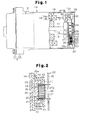
Fig. 1 is a partial cross-sectional view, with a portion cut away, illustrating an electric compressor according to one embodiment; -
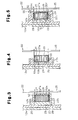
Fig. 2 is a diagram illustrating a fixing structure for a filter coil according to a first embodiment; -
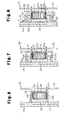
Fig. 3 is a diagram illustrating a fixing structure for a filter coil according to a second embodiment; -
Fig. 4 is a diagram illustrating a fixing structure for a filter coil according to a third embodiment; -
Fig. 5 is a diagram illustrating a fixing structure for a filter coil according to a fourth embodiment; and -
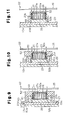
Figs. 6 to 11 are diagrams of modified embodiments, each illustrating a fixing structure for a filter coil that uses a separation member. - A fixing structure for a coil in an electric compressor according to a first embodiment of the present invention will be described with reference to
Figs. 1 and 2 . - As shown in
Fig. 1 , a housing H of anelectric compressor 10 includes a cylindrical aluminum first housing member 11 (on the left inFig. 1 ) with a closed end and a cylindrical aluminum second housing member 12 (on the right inFig. 1 ) with a closed end. The first andsecond housing members first housing member 11 is held in contact with the open end of thesecond housing member 12. In the housing H, anelectric motor 16 is accommodated at a position closer to abottom wall 12a of the second housing member 12 (the right end inFig. 1 ). Also, a compressingportion 15 is accommodated in the first housing member 11 (the left end inFig. 1 ). - A
stator 18 of theelectric motor 16 is fixed to the inner circumferential surface of thesecond housing member 12. Thestator 18 has astator core 18a, about which amotor coil 18b is wound. Arotary shaft 17 is rotationally supported in the housing H via bearings (not shown). Arotor 19 of theelectric motor 16 is fixed to therotary shaft 17 to rotate integrally with therotary shaft 17. Therotary shaft 17 is rotated as theelectric motor 16 operates, which drives thecompressing portion 15. - An annular
circumferential wall 12c extends in a direction opposite to thefirst housing member 11, from the periphery of the outer surface of thebottom wall 12a of thesecond housing member 12. An open end of aninverter cover 20, which is shaped as a box with a closed end, is held in contact with the open end of thecircumferential wall 12c. Anaccommodating space 21 is defined by thebottom wall 12a, thecircumferential wall 12c, and theinverter cover 20 to accommodate aninverter 22, which is a circuit for controlling operation of theelectric motor 16. - The
inverter 22 is attached to the outer surface of thebottom wall 12a with aheat removing member 23 in between. Theheat removing member 23 is a plate made of aluminum, which has high thermal conductivity, is thermally coupled to thebottom wall 12a. Asubstrate support member 24 is fixed to theheat removing member 23. The distal end of thesubstrate support member 24 supports asubstrate 25 of theinverter 22. Theinverter 22 is assembled to theelectric compressor 10 such that the mounting surface of thesubstrate 25 is perpendicular to the direction of the center axis L (axial direction) of therotary shaft 17. Therefore, in the present embodiment, thecompressing portion 15, theelectric motor 16, and theinverter 22 are arranged in order along the axial direction of therotary shaft 17. Electrical components include switching elements (not shown), and afilter coil 27 andcapacitors 28, which function as a noise filter. These components are mounted on thesubstrate 25 via soldering portions (not shown). - A sealed
terminal 30 is fixed to a part of thebottom wall 12a that is close to the outer periphery (in the upper portion as viewed inFig. 1 ). The sealedterminal 30 electrically connects themotor coil 18b of theelectric motor 16 to theinverter 22. The sealedterminal 30 is formed by integrating a conductingpin 33 and an insulatingmember 34. The conductingpin 33 connects a motor-side connector 31, which is connected to themotor coil 18b, to a substrate-side connector 32, which is connected to thesubstrate 25. The insulatingmember 34 fixes the conductingpin 33 to thebottom wall 12a while insulating the conductingpin 33 from thebottom wall 12a. - The structure for fixing the
filter coil 27 to theheat removing member 23 will now be described. - As shown in
Fig. 2 , thefilter coil 27 is formed by winding awire 27a about anannular core 26. The starting point and end point of thewire 27a are connected to thesubstrate 25 via soldering portions (not shown). Thefilter coil 27 is thus mounted on thesubstrate 25. Thefilter coil 27 is received in anaccommodating portion 23b, which serves as a receiving portion and an annular wall. The annularaccommodating portion 23b extends from theheat removing member 23 along the axial direction of therotary shaft 17. Theaccommodating portion 23b is filled with a soft material member, which is acooling gel 29. In addition to heat conductivity, thecooling gel 29 has sufficient adhesion property and shape retention property such that thegel 29 does not leak from theaccommodating portion 23b regardless of the installed orientation of theelectric compressor 10. - The
filter coil 27 is incorporated in theaccommodating portion 23b while being integrated with (coupled to) aresin separation member 40, and fixed to (coupled to) theheat removing member 23 via theseparation member 40. The entire outer circumference of thefilter coil 27 is covered and retained by aretaining portion 41 of theseparation member 40. Theseparation member 40 is formed by placing thefilter coil 27 in a frame (not shown) and filling the frame with molten resin, so that thefilter coil 27 is immovably integrated with the retainingportion 41. -
Legs 42 protrude from an end face of the retainingportion 41 that faces theheat removing member 23. The distal ends of thelegs 42 contact theheat removing member 23. The protruding length of thelegs 42 from the retainingportion 41 is sufficient to allow such contact between thelegs 42 and theheat removing member 23 to insulate thefilter coil 27 from theheat removing member 23. A part of thefilter coil 27 that is radially inside of thelegs 42 is not covered with resin. - Fixing
legs 43 are formed on the outer circumferential surface of the retainingportion 41. The fixinglegs 43 first extend outward from the outer circumferential surface of the retainingportion 41 over theaccommodating portion 23b, and then turn and extend toward theheat removing member 23. A fixingpiece 43a is formed at the distal end of each fixingleg 43. Ascrew 50 is passed through each fixingpiece 43a and threaded to theheat removing member 23, so that theseparation member 40 is fixed to (coupled to) theheat removing member 23. - With the
separation member 40 fixed to theheat removing member 23, the half of thefilter coil 27 that corresponds to theheat removing member 23 is located in theaccommodating portion 23b, and a part of thefilter coil 27 that is exposed from the retainingportion 41 contact the coolinggel 29. By the contact between thelegs 42 and theheat removing member 23, thefilter coil 27 is positioned to be isolated from theheat removing member 23 by the distance corresponding to the length of thelegs 42. - When securing the
inverter 22, which has thefilter coil 27, to theheat removing member 23, thefilter coil 27 retained by theseparation member 40 is prepared. Then, theaccommodating portion 23b is filled with the coolinggel 29, and the retainingportion 41 of theseparation member 40 is inserted into theaccommodating portion 23b. After thelegs 42 contact theheat removing member 23, thescrews 50 passed through the fixingpieces 43a of the fixinglegs 43 are threaded to theheat removing member 23. Lastly, thesubstrate 25, on which electrical components such as thecapacitors 28 are mounted, is placed on thefilter coil 27, and thefilter coil 27 is soldered to thesubstrate 25. As a result, thefilter coil 27 is fixed to theheat removing member 23 via theseparation member 40 byscrews 50, and theinverter 22 is fixed to theheat removing member 23. Thesubstrate 25 contacts and is supported by thesubstrate support member 24, and thecapacitors 28 contact theheat removing member 23. - Operation of the structure for fixing the
filter coil 27 will now be described. - The
filter coil 27 is immovably retained by the retainingportion 41 of theseparation member 40, and theseparation member 40 is fixed to theheat removing member 23 by the fixinglegs 43. Accordingly, even if theelectric compressor 10 vibrates, the vibration is absorbed by theseparation member 40, so that thefilter coil 27 is prevented from vibrating. Further, thefilter coil 27 is fixed to theheat removing member 23 by means of theseparation member 40. Therefore, thefilter coil 27 alone can be assembled with theheat removing member 23, separately from the assembly of thesubstrate 25. - Further, the
filter coil 27 is inserted into theaccommodating portion 23b of theheat removing member 23. A part of thefilter coil 27 that is radially inside of thelegs 42 is not covered with resin and contacts the coolinggel 29 in theaccommodating portion 23b. This contact causes some of the heat generated by energizing thefilter coil 27 to be removed by theheat removing member 23 via the coolinggel 29. The heat removing effect cools thefilter coil 27. In addition, the contact of thelegs 42 with theheat removing member 23 insulates thefilter coil 27 from theheat removing member 23. - The first embodiment has the following advantages.
- (1) The annular
accommodating portion 23b extends from theheat removing member 23. Thefilter coil 27 is incorporated in theaccommodating portion 23b filled with the coolinggel 29 and contacts the coolinggel 29. Thefilter coil 27 is therefore cooled by the heat removing effect of the coolinggel 29 and theheat removing member 23. - (2) The
filter coil 27 is fixed to theheat removing member 23 by means of theseparation member 40. Therefore, thefilter coil 27 alone can be assembled with theheat removing member 23, separately from the assembly of thesubstrate 25. Thus, unlike a case where thefilter coil 27 is fixed only to thesubstrate 25, theseparation member 40 prevents thefilter coil 27 from contacting thesecond housing member 12 and theheat removing member 23 when thefilter coil 27 is placed in theaccommodating space 21. Therefore, the coating of thefilter coil 27 is prevented from being damaged. Further, thefilter coil 27 is not only suspended from thesubstrate 25, but also retained by theseparation member 40. Therefore, stress does not act only on the soldering portions between thefilter coil 27 and thesubstrate 25, and the soldering portions are not damaged. - (3) In the
separation member 40, thelegs 42 extend from the retainingportion 41, which retains thefilter coil 27. Therefore, with theseparation member 40 fixed to theheat removing member 23, thelegs 42 contact theheat removing member 23, so that thefilter coil 27 is isolated from theheat removing member 23. Thefilter coil 27 is thus reliably insulated from theheat removing member 23 by thelegs 42. - (4) The
separation member 40 is fixed to theheat removing member 23 by thescrews 50. Therefore, even if theelectric compressor 10 vibrates, theseparation member 40 is prevented from being displaced, and thefilter coil 27 can be positioned in theaccommodating portion 23b. Theseparation member 40 is fixed to theheat removing member 23 by the fixinglegs 43, which extend to the outside of theaccommodating portion 23b, to theheat removing member 23 by thescrews 50. If parts for fixing theseparation member 40 to theheat removing member 23, or the fixinglegs 43, are located in theaccommodating portion 23b, the coolinggel 29 would leak. The present embodiment eliminates such a drawback. The coolinggel 29 is thus retained in theaccommodating portion 23b, so that the heat removing effect of theheat removing member 23 via the coolinggel 29 is prevented from being lowered. - (5) The
filter coil 27 is a relatively heavy component. Therefore, if thefilter coil 27 is fixed to thesubstrate 25 at the ends of its wire, thefilter coil 27 would be easily vibrated, significantly unstable, and easily influenced by vibration of theelectric compressor 10. However, since thefilter coil 27 is integrated with theseparation member 40, and theseparation member 40 is fixed to theheat removing member 23, vibration of thefilter coil 27 is effectively suppressed. - (6) The
inverter 22 is arranged such that the mounting surface of thesubstrate 25 is perpendicular to the axial direction of theelectric compressor 10. Thefilter coil 27 of theinverter 22 is inserted into the annularaccommodating portion 23b. Theaccommodating portion 23b extends from theheat removing member 23 along the axial direction of theelectric compressor 10. Theaccommodating portion 23b is filled with the coolinggel 29 for cooling thefilter coil 27. Therefore, theaccommodating portion 23b prevents the coolinggel 29 from flowing to a position where the coolinggel 29 cannot contact thefilter coil 27. The heat removing effect from thefilter coil 27 using the coolinggel 29 is thus maintained. - (7) In the
separation member 40, thelegs 42 extend from the retainingportion 41, which retains thefilter coil 27. Therefore, when inserting thefilter coil 27 into theaccommodating portion 23b, and thelegs 42 contact theheat removing member 23, it is possible to check whether thefilter coil 27 is at a sufficient insulating distance from theheat removing member 23. This facilitates the fixation of theinverter 22. - (8) When the
inverter 22 is fixed to theheat removing member 23, theaccommodating portion 23b is inserted into thefilter coil 27 after filling theaccommodating portion 23b with the coolinggel 29. This pushes thefilter coil 27 into the coolinggel 29, ensuring contact between thefilter coil 27 and the coolinggel 29. Compared to a case where theaccommodating portion 23b is filled with the coolinggel 29 after thefilter coil 27 is inserted into theaccommodating portion 23b, theaccommodating portion 23b, theseparation member 40 does not hamper the filling process, so that theaccommodating portion 23b is easily filled with the coolinggel 29. - (9) The
filter coil 27 of theinverter 22 is immovably integrated with theseparation member 40 by resin molding. Theseparation member 40 is fixed to theheat removing member 23 at a position outside of theaccommodating portion 23b. This allows thefilter coil 27 to be positioned and retained in the retainingportion 41. Also, since vibration of theelectric compressor 10 is absorbed by theseparation member 40, vibration of thefilter coil 27 is suppressed. - A second embodiment of the present invention will now be described with reference to
Fig. 3 . In the following description, like or the same reference numerals are given to those components that are like or the same as the corresponding components of the first embodiment and detailed explanations are omitted or simplified. - As shown in
Fig. 3 , anseparation member 52 of the second embodiment includes a disk-shapedbottom plate 52a and anannular side wall 52b that protrudes from the periphery of thebottom plate 52a, so that theseparation member 52 has a cylindrical shape with a bottom and an opening toward theheat removing member 23. Thefilter coil 27 is fitted in theseparation member 52 to contact the inner surface of thebottom plate 52a of theseparation member 52, and the inner surface of theside wall 52b is pressed against thefilter coil 27. Accordingly, thefilter coil 27 is coupled to and retained in theseparation member 52. The protruding length of theside wall 52b from thebottom plate 52a is longer than the axial length of thefilter coil 27. Further, the protruding length of theside wall 52b from thebottom plate 52a is sufficient to ensure insulation between thefilter coil 27 and theheat removing member 23 with the distal end of theside wall 52b contacting theheat removing member 23. Theseparation member 52 is filled with the coolinggel 29. The opening end of theside wall 52b is bonded to theheat removing member 23 so that theseparation member 52 is coupled to theheat removing member 23. - Accordingly, the second embodiment has the following advantages in addition to the advantages (1), (2), (5), (6), and (8) of the first embodiment.
- (10) The
filter coil 27 is retained in theseparation member 52, which has a cylindrical shape with a bottom, and theside wall 52b of theseparation member 52 is pressed against the outer circumferential surface of thefilter coil 27. This suppresses vibration of thefilter coil 27. - (11) The protruding length of the
side wall 52b from thebottom plate 52a is longer than the axial length of thefilter coil 27 and sufficient to ensure insulation between thefilter coil 27 and theheat removing member 23 with theside wall 52b contacting theheat removing member 23. Therefore, thefilter coil 27 and theheat removing member 23 can be insulated from each other simply by brining theseparation member 52 and theheat removing member 23 into contact with each other. - A third embodiment of the present invention will now be described with reference to
Fig. 4 . In the following description, like or the same reference numerals are given to those components that are like or the same as the corresponding components of the first embodiment and detailed explanations are omitted or simplified. - As shown in
Fig. 4 , aseparation member 53 of the third embodiment is formed to be cylindrical and hasarms 53a extending from a part of its inner circumferential surface that is close to theheat removing member 23. Asupport portion 53b projects from eacharm 53a in a direction away from theheat removing member 23. The outer diameter of theseparation member 53 is slightly less than the inner diameter of theaccommodating portion 23b of theheat removing member 23. The inner diameter of theseparation member 53 is slightly less than the outer diameter of thefilter coil 27. - The
separation member 53 is fitted in theaccommodating portion 23b to be coupled to theheat removing member 23. Thefilter coil 27 is fitted in theseparation member 53, so that theseparation member 53 is coupled to and retained by thefilter coil 27. Thefilter coil 27 is supported by thesupport portion 53b. The length of thesupport portion 53b along the axial direction of thefilter coil 27 is sufficient to ensure insulation between thefilter coil 27 and theheat removing member 23. Theseparation member 53 is filled with the coolinggel 29. - Accordingly, the third embodiment has the following advantages in addition to the advantages (1), (2), (5), (6), and (8) of the first embodiment.
- (12) The outer diameter of the
cylindrical separation member 53 is slightly less than the inner diameter of theaccommodating portion 23b. Theaccommodating portion 23b can be easily coupled to theseparation member 53 by fitting theseparation member 53 in theaccommodating portion 23b. - (13) The inner diameter of the
cylindrical separation member 53 is slightly less than the outer diameter of thefilter coil 27. Thearm 53a extends from a part of the inner circumferential surface of theseparation member 53 that is close to theheat removing member 23. Thesupport portion 53b projects from thearm 53a. Therefore, by simply fitting thefilter coil 27 into theseparation member 53, thefilter coil 27 can be coupled to and retained by theseparation member 53. Also, thefilter coil 27 can be supported while ensuring insulation between thefilter coil 27 and theheat removing member 23. - A fourth embodiment of the present invention will now be described with reference to
Fig. 5 . In the following description, like or the same reference numerals are given to those components that are like or the same as the corresponding components of the first embodiment and detailed explanations are omitted or simplified. - As shown in
Fig. 5 , anseparation member 55 of the fourth embodiment includes anannular side wall 55b,contact pieces 55c extending toward the center of theseparation member 55 from the inner surface of the open end of theside wall 55b close to theheat removing member 23, and arim 55d that extends from the outer circumference surface of theside wall 55b to reach the end face of theaccommodating portion 23b. Thefilter coil 27 is fitted in theseparation member 55 to contact thecontact pieces 55c. Accordingly, thefilter coil 27 is coupled to and retained in theseparation member 55. - The
separation member 55, which accommodates thefilter coil 27, has an open end close to thesubstrate 25. The open end close to thesubstrate 25 is sealed by alid member 55f. Thelid member 55f is inserted into theseparation member 55, and the inner surface of thelid member 55f is bonded to the outer surface of theseparation member 55 with adhesive. The end face of thelid member 55f that faces theinverter 22 is flush with the end face of therim 55d that faces theinverter 22. Ascrew 50 is passed through therim 55d and threaded to the end face of theaccommodating portion 23b, in which cooling gel is contained in advance. Accordingly, with thelid member 55f bonded thereto, theseparation member 55, which accommodates thefilter coil 27, is fixed to (coupled to) theheat removing member 23. - The length of the
accommodating portion 23b along the axial direction of thefilter coil 27 is longer than the length from therim 55d to eachcontact piece 55c. Further, the length from the end face of thefilter coil 27 that faces theheat removing member 23 to theheat removing member 23 is long enough to ensure insulation between thefilter coil 27 and theheat removing member 23 when therim 55d is threaded to the end face of theaccommodating portion 23b. The coolinggel 29 enters theseparation member 55 through clearances between thecontact pieces 55c and contacts thefilter coil 27. - Accordingly, the fourth embodiment has the following advantages in addition to the advantages (1), (2), (4), (5), (6), and (8) of the first embodiment.
- (14) The
separation member 55 is shaped to be annular and has thecontact pieces 55c at the open end. Theseparation member 55 has therim 55d, which is threaded to the end face of theaccommodating portion 23b. Thecontact pieces 55c and therim 55d separate thefilter coil 27 from theheat removing member 23. Thefilter coil 27 is thus insulated from theheat removing member 23. - (15) The
separation member 55, which accommodates thefilter coil 27, has an open end close to thesubstrate 25, and the open end is sealed by thelid member 55f. Accordingly, thefilter coil 27 is reliably retained in theseparation member 55. - Each of the embodiments may be modified as follows.
- The
separation member 52 of the second embodiment may be modified as shown inFig. 6 . That is, theside wall 52b of theseparation member 52 may be fitted in theaccommodating portion 23b. In this case, theseparation member 52 can be easily coupled to theaccommodating portion 23b. Even if theelectric compressor 10 vibrates, the outer surface of theside wall 52b instantly contacts the inner surface of theaccommodating portion 23b. Therefore, vibration of thefilter coil 27 is reliably suppressed by theseparation member 52. - The
separation member 52 of the second embodiment may be modified as shown inFig. 7 . That is, an outwardly extendingrim 57 may be formed on the outer circumference surface of theside wall 52b of theseparation member 52, and an annular portion, or anouter wall 58, may be formed on the periphery of therim 57. The inner diameter of theouter wall 58 is slightly greater than the outer diameter of theaccommodating portion 23b. Theouter wall 58 may be fitted from outside about theaccommodating portion 23b to couple theseparation member 52 to theheat removing member 23. In this case, theseparation member 52 can be easily coupled to theheat removing member 23. If theelectric compressor 10 vibrates, the inner surface of theouter wall 58 instantly contacts the outer surface of theaccommodating portion 23b. Therefore, vibration of thefilter coil 27 is reliably suppressed by theseparation member 52. - The
separation member 52 of the second embodiment may be modified as shown inFig. 8 . That is,extensions 59 are formed on the outer circumferential surface of theside wall 52b of theseparation member 52. Theextensions 59 extend beyond theaccommodating portion 23b. A fixingarm 60 extends from eachextension 59 toward the opening of the separation member 52 (in a direction toward the heat removing member 23). A fixingpiece 61 is formed at the distal end of each fixingarm 60. Ascrew 62 is passed through each fixingpiece 61 and threaded to theheat removing member 23, so that theseparation member 52 is coupled to (fixed to) theheat removing member 23. - Since the
separation member 52 is fixed to theheat removing member 23 by thescrews 62, theseparation member 52 is prevented from being displaced even if theelectric compressor 10 vibrates, and thefilter coil 27 is reliably positioned. Theseparation member 52 is fixed to theheat removing member 23 by the fixingarms 60, which extend to the outside of theaccommodating portion 23b, to theheat removing member 23 by thescrews 62. If parts for fixing theseparation member 52 to theheat removing member 23, or the fixingarms 60, are located in theaccommodating portion 23b, the coolinggel 29 would leak. The present embodiment eliminates such a drawback. The coolinggel 29 is thus retained in theaccommodating portion 23b, so that the heat removing effect of theheat removing member 23 via the coolinggel 29 is prevented from being lowered. - The
separation member 52 of the second embodiment may be modified as shown inFig. 9 . That is,extensions 59 are formed on the outer circumferential surface of theside wall 52b of theseparation member 52. Theextensions 59 extend outward. A fixingarm 60 extends from eachextension 59 toward the opening of the separation member 52 (in a direction toward the heat removing member 23). An outwardly extending fixingpiece 63 is formed at the distal end of each fixingarm 60. Anengaging portion 63a protrudes from an end face of each fixingpiece 63 facing theheat removing member 23, and a correspondingengaging recess 23d is formed in theheat removing member 23. The engaging recesses 23d and the engagingportions 63a form a recess-projection engaging structure. Theseparation member 52 may be coupled to theheat removing member 23 by engaging the engagingportions 63a with the engagingrecesses 23d. Accordingly, theseparation member 52 can be coupled to theheat removing member 23 by simply engaging the engagingportions 63a with the engagingrecesses 23d. - The
separation member 52 of the second embodiment may be modified as shown inFig. 10 . That is,extensions 59 are formed on the outer circumferential surface of theside wall 52b of theseparation member 52. Theextensions 59 extend outward. An engagingportion 65 extends from eachextension 59 toward the opening of the separation member 52 (in a direction toward the heat removing member 23).Engaging recesses 23f, which are engageable with the engagingportions 65, are formed at the open end of theaccommodating portion 23b. The engaging recesses 23f and the engagingportions 65 form a recess-projection engaging structure. Theseparation member 52 may be coupled to theheat removing member 23 by engaging the engagingportions 65 of theseparation member 52 with the engagingrecesses 23f of theheat removing member 23. Accordingly, theseparation member 52 can be coupled to theheat removing member 23 by simply engaging the engagingportions 65 with the engagingrecesses 23f. - The
separation member 52 of the second embodiment may be modified as shown inFig. 11 . That is, engagingportions 66 are formed on the outer circumferential surface of theside wall 52b of theseparation member 52. The engagingportions 66 project outward. Engaging recesses 23g, which are engageable with the engagingportions 66, are formed on the inner circumferential surface of theaccommodating portion 23b. The engaging recesses 23g and the engagingportions 66 form a recess-projection engaging structure. Theseparation member 52 may be coupled to theheat removing member 23 by fitting theside wall 52b of theseparation member 52 into theaccommodating portion 23b and engaging the engagingportions 66 with the engaging recesses 23g. This allows theseparation member 52 to be easily and firmly coupled to theheat removing member 23 by two simple methods, or fitting and engagement. - In each embodiment, the
filter coil 27 is used as an electrical component. That is, an separation member is coupled to thefilter coil 27 to form a fixing structure. However, thecapacitors 28 or the switching elements may be used as electrical components coupled to an separation member to form a fixing structure. - A coil that is fixed by the fixing structure according to each embodiment does not need to be a filter coil, but may be a coil for other uses.
- The fixing structure according to each embodiment is applied to the
filter coil 27, which is mounted on an inverter 22 (operation control circuit) for theelectric motor 16 in theelectric compressor 10. However, the fixing structure may be applied to afilter coil 27 mounted on an inverter for a motor in a device other than theelectric compressor 10. Alternatively, the fixing structure may be applied to a coil mounted on an operation control circuit for a device other than a motor. - A fixing structure for an electrical component includes a heat removing member for removing heat from the electrical component. The heat removing member has a receiving portion for receiving the electrical component. The fixing structure for an electrical component further includes a separation member that is coupled to the electrical component to separate the electrical component from the heat removing member. The separation member is coupled to the heat removing member. The fixing structure for an electrical component includes a soft material member that is accommodated in the receiving portion to contact the receiving portion and the electrical component. Heat of the electrical component is transmitted to the heat removing member via the soft material member.
Claims (8)
- A fixing structure for an electrical component, comprising:a heat removing member (23) for removing heat from an electrical component, the heat removing member (23) having a receiving portion for receiving the electrical component (27);a separation member (40, 52, 53, 55) that is coupled to the electrical component to separate the electrical component from the heat removing member, wherein the separation member (40, 52, 53, 55) is coupled to the heat removing member (23); anda soft material member (29) that is accommodated in the receiving portion (23b) to contact the receiving portion (23b) and the electrical component (27), wherein heat of the electrical component is transmitted to the heat removing member (23) via the soft material member.
- The fixing structure for an electrical component according to claim 1, wherein the receiving portion (23b) is an annular wall that extends from the heat removing member (23).
- The fixing structure for an electrical component according to claim 2, wherein the separation member (40, 55) is coupled either to the annular wall (23b) or the heat removing member (23) at a position outside the annular wall.
- The fixing structure for an electrical component according to claim 3, wherein the separation member (40, 55) is secured to the heat removing member (23) by screws.
- The fixing structure for an electrical component according to any one of claims 2 to 4, wherein the separation member (52) has an annular portion (58), the annular portion being fitted to the annular wall.
- The fixing structure for an electrical component according to any one of claims 1 to 5, wherein the separation member (52) is engaged with the heat removing member (23) by a recess-projection engaging structure (63a, 65, 66).
- The fixing structure for an electrical component according to any one of claims 1 to 6, wherein the electrical component (27) is a coil.
- The fixing structure for an electrical component according to claim 7, wherein the coil is used in an operation control circuit (22) of a motor (16) for an electric compressor (10).
Applications Claiming Priority (2)
| Application Number | Priority Date | Filing Date | Title |
|---|---|---|---|
| JP2011001431 | 2011-01-06 | ||
| JP2011286775A JP5626200B2 (en) | 2011-01-06 | 2011-12-27 | Electrical component fixing structure |
Publications (3)
| Publication Number | Publication Date |
|---|---|
| EP2475080A2 true EP2475080A2 (en) | 2012-07-11 |
| EP2475080A3 EP2475080A3 (en) | 2014-10-29 |
| EP2475080B1 EP2475080B1 (en) | 2017-10-04 |
Family
ID=45440420
Family Applications (1)
| Application Number | Title | Priority Date | Filing Date |
|---|---|---|---|
| EP12150050.8A Active EP2475080B1 (en) | 2011-01-06 | 2012-01-03 | Fixing structure for electrical component |
Country Status (4)
| Country | Link |
|---|---|
| US (1) | US9065317B2 (en) |
| EP (1) | EP2475080B1 (en) |
| JP (1) | JP5626200B2 (en) |
| CN (1) | CN102588248B (en) |
Cited By (1)
| Publication number | Priority date | Publication date | Assignee | Title |
|---|---|---|---|---|
| FR3071696A1 (en) * | 2017-09-27 | 2019-03-29 | Valeo Japan Co., Ltd. | CONTROL UNIT FOR AN ELECTRICAL COMPRESSOR FOR COOLING AT LEAST ONE ELECTRONIC COMPONENT |
Families Citing this family (20)
| Publication number | Priority date | Publication date | Assignee | Title |
|---|---|---|---|---|
| JP5949681B2 (en) * | 2013-06-25 | 2016-07-13 | 株式会社豊田自動織機 | Electric compressor |
| JP5861673B2 (en) | 2013-06-25 | 2016-02-16 | 株式会社豊田自動織機 | Electric compressor |
| JP6225010B2 (en) * | 2013-12-09 | 2017-11-01 | カルソニックカンセイ株式会社 | Electric compressor assembly method and electric compressor |
| JP6245075B2 (en) * | 2014-05-28 | 2017-12-13 | アイシン・エィ・ダブリュ株式会社 | Vehicle drive device |
| US9420724B2 (en) * | 2014-11-04 | 2016-08-16 | Ge Aviation Systems Llc | Power converter assembly |
| JP6210601B2 (en) * | 2014-12-17 | 2017-10-11 | オートリブ日信ブレーキシステムジャパン株式会社 | Electronic control unit |
| JP2016119798A (en) * | 2014-12-22 | 2016-06-30 | 株式会社オートネットワーク技術研究所 | Circuit structure and electric connection box |
| JPWO2017051551A1 (en) * | 2015-09-24 | 2017-09-28 | 日立オートモティブシステムズ株式会社 | In-vehicle device noise filter and in-vehicle device |
| JP6754032B2 (en) * | 2016-03-16 | 2020-09-09 | 北川工業株式会社 | Manufacturing method of inductor carrier |
| JP6627666B2 (en) * | 2016-07-07 | 2020-01-08 | 株式会社オートネットワーク技術研究所 | Circuit board and electrical junction box |
| JP2018022736A (en) * | 2016-08-02 | 2018-02-08 | 株式会社豊田自動織機 | Toroidal coil cooling structure |
| JP6720860B2 (en) * | 2016-12-27 | 2020-07-08 | 株式会社豊田自動織機 | Electric compressor |
| DE102017109321A1 (en) | 2017-05-02 | 2018-11-08 | Hanon Systems | EMC filters |
| DE102018211413A1 (en) * | 2018-07-10 | 2020-01-16 | Brose Fahrzeugteile Gmbh & Co. Kommanditgesellschaft, Bamberg | accessory |
| JP7129658B2 (en) * | 2018-09-14 | 2022-09-02 | パナソニックIpマネジメント株式会社 | Power conversion device, reactor device and heat dissipation structure |
| JP7095611B2 (en) * | 2019-01-31 | 2022-07-05 | 株式会社豊田自動織機 | Electric compressor |
| JP7268508B2 (en) * | 2019-07-09 | 2023-05-08 | 株式会社デンソー | Coil module and power converter |
| JP7488988B2 (en) | 2021-07-27 | 2024-05-23 | 株式会社豊田自動織機 | Electric Compressor |
| CN116437624A (en) * | 2022-01-11 | 2023-07-14 | 开利公司 | mechanical enclosure |
| JP7855987B2 (en) * | 2022-10-31 | 2026-05-11 | 株式会社豊田自動織機 | Electric compressor |
Citations (1)
| Publication number | Priority date | Publication date | Assignee | Title |
|---|---|---|---|---|
| JP2007295639A (en) | 2006-04-20 | 2007-11-08 | Denso Corp | Vehicle motor drive device |
Family Cites Families (35)
| Publication number | Priority date | Publication date | Assignee | Title |
|---|---|---|---|---|
| EP0800940A3 (en) * | 1996-04-10 | 2001-06-06 | Denso Corporation | Vehicular air conditioning system for electric vehicles |
| DE19645636C1 (en) * | 1996-11-06 | 1998-03-12 | Telefunken Microelectron | Power module for operating electric motor with speed and power control |
| JP3927689B2 (en) * | 1998-06-19 | 2007-06-13 | 新日本無線株式会社 | Microwave communication equipment |
| JP3881488B2 (en) | 1999-12-13 | 2007-02-14 | 株式会社東芝 | Circuit module cooling device and electronic apparatus having the cooling device |
| ES2266572T3 (en) * | 2001-09-27 | 2007-03-01 | Siemens Aktiengesellschaft | ELECTRICAL CIRCUIT SYSTEM FORMED BY VARIOUS ELECTRONIC UNITED CIRCUIT COMPONENTS BETWEEN YES. |
| JP4611820B2 (en) * | 2005-07-04 | 2011-01-12 | 本田技研工業株式会社 | Cooling device for electric unit for vehicle |
| JP4315141B2 (en) * | 2005-09-09 | 2009-08-19 | セイコーエプソン株式会社 | Electronic component temperature control device and handler device |
| US7176707B1 (en) * | 2006-02-23 | 2007-02-13 | Lockheed Martin Corporation | Back side component placement and bonding |
| US20070201209A1 (en) * | 2006-02-27 | 2007-08-30 | Francis Sally J | Connection apparatus and method |
| CN100574592C (en) * | 2006-03-17 | 2009-12-23 | 富准精密工业(深圳)有限公司 | Radiator Fixture |
| JP4992287B2 (en) * | 2006-04-28 | 2012-08-08 | 日本電産株式会社 | motor |
| US7710726B2 (en) * | 2006-09-13 | 2010-05-04 | Panasonic Corporation | Electronic circuit apparatus for compressor |
| US8007255B2 (en) * | 2006-11-22 | 2011-08-30 | Mitsubishi Heavy Industries, Ltd. | Inverter-integrated electric compressor with inverter storage box arrangement |
| JP4992395B2 (en) | 2006-11-27 | 2012-08-08 | 株式会社豊田自動織機 | Electric compressor |
| JP4452952B2 (en) * | 2007-06-20 | 2010-04-21 | 日立オートモティブシステムズ株式会社 | Power converter |
| JP4452953B2 (en) * | 2007-08-09 | 2010-04-21 | 日立オートモティブシステムズ株式会社 | Power converter |
| DE102007043886A1 (en) * | 2007-09-14 | 2009-04-09 | Continental Automotive Gmbh | Electrical device for use in high-vibration environments and attenuator |
| JP4934559B2 (en) * | 2007-09-27 | 2012-05-16 | オンセミコンダクター・トレーディング・リミテッド | Circuit device and manufacturing method thereof |
| US9342121B2 (en) * | 2008-05-06 | 2016-05-17 | International Business Machines Corporatoin | Cooling system for electronic components |
| JP5117287B2 (en) | 2008-06-06 | 2013-01-16 | 株式会社日立製作所 | Electronic equipment cooling system |
| JP4657329B2 (en) * | 2008-07-29 | 2011-03-23 | 日立オートモティブシステムズ株式会社 | Power converter and electric vehicle |
| JP4708459B2 (en) * | 2008-07-29 | 2011-06-22 | 日立オートモティブシステムズ株式会社 | Power converter |
| JP2010041735A (en) * | 2008-07-31 | 2010-02-18 | Tateyama Machine Kk | Electromagnetic brake for linear motor |
| JP4988665B2 (en) * | 2008-08-06 | 2012-08-01 | 日立オートモティブシステムズ株式会社 | Semiconductor device and power conversion device using the semiconductor device |
| JP4473923B2 (en) * | 2008-10-22 | 2010-06-02 | 株式会社東芝 | Electronics |
| JP5412098B2 (en) * | 2008-12-05 | 2014-02-12 | 三菱重工業株式会社 | Inverter-integrated electric compressor and its inverter device |
| US8441827B2 (en) * | 2009-03-11 | 2013-05-14 | Caterpillar Inc. | Power converter assembly having a housing |
| JP5129195B2 (en) * | 2009-05-26 | 2013-01-23 | 三菱電機株式会社 | Voltage regulator for vehicle alternator |
| JP5435286B2 (en) * | 2009-06-24 | 2014-03-05 | 株式会社デンソー | Drive device |
| US20100328885A1 (en) * | 2009-06-26 | 2010-12-30 | Scofield William H | Rotatable Cooling Module |
| US8324769B2 (en) * | 2009-09-23 | 2012-12-04 | Rbc Manufacturing Corporation | Motor controller for an electric motor |
| JP5517650B2 (en) * | 2010-02-01 | 2014-06-11 | 三菱重工業株式会社 | Inverter-integrated electric compressor |
| US8553414B2 (en) * | 2010-12-07 | 2013-10-08 | Ut-Battelle, Llc | Gas cooled traction drive inverter |
| JP5249365B2 (en) * | 2011-01-26 | 2013-07-31 | 三菱電機株式会社 | Power converter |
| US8897013B2 (en) * | 2011-02-17 | 2014-11-25 | Lear Corporation | Sealed battery charger housing |
-
2011
- 2011-12-27 JP JP2011286775A patent/JP5626200B2/en active Active
- 2011-12-31 CN CN201110460633.7A patent/CN102588248B/en active Active
-
2012
- 2012-01-03 EP EP12150050.8A patent/EP2475080B1/en active Active
- 2012-01-04 US US13/343,203 patent/US9065317B2/en active Active
Patent Citations (1)
| Publication number | Priority date | Publication date | Assignee | Title |
|---|---|---|---|---|
| JP2007295639A (en) | 2006-04-20 | 2007-11-08 | Denso Corp | Vehicle motor drive device |
Cited By (1)
| Publication number | Priority date | Publication date | Assignee | Title |
|---|---|---|---|---|
| FR3071696A1 (en) * | 2017-09-27 | 2019-03-29 | Valeo Japan Co., Ltd. | CONTROL UNIT FOR AN ELECTRICAL COMPRESSOR FOR COOLING AT LEAST ONE ELECTRONIC COMPONENT |
Also Published As
| Publication number | Publication date |
|---|---|
| EP2475080A3 (en) | 2014-10-29 |
| JP5626200B2 (en) | 2014-11-19 |
| CN102588248B (en) | 2015-11-04 |
| EP2475080B1 (en) | 2017-10-04 |
| JP2012156496A (en) | 2012-08-16 |
| CN102588248A (en) | 2012-07-18 |
| US20120175981A1 (en) | 2012-07-12 |
| US9065317B2 (en) | 2015-06-23 |
Similar Documents
| Publication | Publication Date | Title |
|---|---|---|
| US9065317B2 (en) | Fixing structure for electrical component | |
| US9893586B2 (en) | Driver apparatus provided with a motor and a control unit | |
| US11258330B2 (en) | Rotating electrical device | |
| US10673309B2 (en) | Inverter-integrated motor | |
| JP6432235B2 (en) | Electric pump | |
| CN104871407B (en) | motor | |
| CN103004059B (en) | Brushless motor and manufacturing method thereof | |
| JP6009856B2 (en) | Rotating electric machine | |
| US8704417B2 (en) | Motor control unit and brushless motor | |
| CN102536738B (en) | Electric compressor | |
| KR101895067B1 (en) | Electric motor, in particular radiator fan motor | |
| JP5518255B2 (en) | Drive unit-integrated rotating electrical machine | |
| CN110771017A (en) | Electric drive unit with housing | |
| JP2017221083A (en) | Inverter integrated rotary electric machine | |
| JP2013062899A (en) | Brushless motor | |
| JP2022080963A (en) | Pump device | |
| JP6112080B2 (en) | Electric compressor | |
| JP6177454B2 (en) | Electric motor and exhaust fan | |
| US10855133B2 (en) | Drive device | |
| CN107294253B (en) | Motor and method of manufacturing same | |
| JP5420040B1 (en) | Rotating electric machine | |
| JP2018206958A (en) | Electronic equipment | |
| CN206992848U (en) | Fan motor | |
| JP3055962B2 (en) | Splash-proof motor | |
| JP6345283B1 (en) | Controller-integrated rotating electrical machine |
Legal Events
| Date | Code | Title | Description |
|---|---|---|---|
| PUAI | Public reference made under article 153(3) epc to a published international application that has entered the european phase |
Free format text: ORIGINAL CODE: 0009012 |
|
| 17P | Request for examination filed |
Effective date: 20120103 |
|
| AK | Designated contracting states |
Kind code of ref document: A2 Designated state(s): AL AT BE BG CH CY CZ DE DK EE ES FI FR GB GR HR HU IE IS IT LI LT LU LV MC MK MT NL NO PL PT RO RS SE SI SK SM TR |
|
| AX | Request for extension of the european patent |
Extension state: BA ME |
|
| PUAL | Search report despatched |
Free format text: ORIGINAL CODE: 0009013 |
|
| AK | Designated contracting states |
Kind code of ref document: A3 Designated state(s): AL AT BE BG CH CY CZ DE DK EE ES FI FR GB GR HR HU IE IS IT LI LT LU LV MC MK MT NL NO PL PT RO RS SE SI SK SM TR |
|
| AX | Request for extension of the european patent |
Extension state: BA ME |
|
| RIC1 | Information provided on ipc code assigned before grant |
Ipc: H02K 9/22 20060101ALI20140924BHEP Ipc: H02K 11/00 20060101AFI20140924BHEP Ipc: H05K 7/20 20060101ALI20140924BHEP |
|
| REG | Reference to a national code |
Ref country code: DE Ref legal event code: R079 Ref document number: 602012038031 Country of ref document: DE Free format text: PREVIOUS MAIN CLASS: H02K0011000000 Ipc: H02K0011330000 |
|
| GRAP | Despatch of communication of intention to grant a patent |
Free format text: ORIGINAL CODE: EPIDOSNIGR1 |
|
| RIC1 | Information provided on ipc code assigned before grant |
Ipc: H02K 9/22 20060101ALI20170420BHEP Ipc: H05K 7/20 20060101ALI20170420BHEP Ipc: H02K 11/33 20160101AFI20170420BHEP |
|
| INTG | Intention to grant announced |
Effective date: 20170523 |
|
| GRAA | (expected) grant |
Free format text: ORIGINAL CODE: 0009210 |
|
| GRAS | Grant fee paid |
Free format text: ORIGINAL CODE: EPIDOSNIGR3 |
|
| AK | Designated contracting states |
Kind code of ref document: B1 Designated state(s): AL AT BE BG CH CY CZ DE DK EE ES FI FR GB GR HR HU IE IS IT LI LT LU LV MC MK MT NL NO PL PT RO RS SE SI SK SM TR |
|
| REG | Reference to a national code |
Ref country code: GB Ref legal event code: FG4D |
|
| REG | Reference to a national code |
Ref country code: CH Ref legal event code: EP |
|
| REG | Reference to a national code |
Ref country code: AT Ref legal event code: REF Ref document number: 934883 Country of ref document: AT Kind code of ref document: T Effective date: 20171015 |
|
| REG | Reference to a national code |
Ref country code: IE Ref legal event code: FG4D |
|
| REG | Reference to a national code |
Ref country code: DE Ref legal event code: R096 Ref document number: 602012038031 Country of ref document: DE |
|
| REG | Reference to a national code |
Ref country code: NL Ref legal event code: MP Effective date: 20171004 |
|
| REG | Reference to a national code |
Ref country code: LT Ref legal event code: MG4D |
|
| REG | Reference to a national code |
Ref country code: AT Ref legal event code: MK05 Ref document number: 934883 Country of ref document: AT Kind code of ref document: T Effective date: 20171004 |
|
| PG25 | Lapsed in a contracting state [announced via postgrant information from national office to epo] |
Ref country code: NL Free format text: LAPSE BECAUSE OF FAILURE TO SUBMIT A TRANSLATION OF THE DESCRIPTION OR TO PAY THE FEE WITHIN THE PRESCRIBED TIME-LIMIT Effective date: 20171004 |
|
| PG25 | Lapsed in a contracting state [announced via postgrant information from national office to epo] |
Ref country code: SE Free format text: LAPSE BECAUSE OF FAILURE TO SUBMIT A TRANSLATION OF THE DESCRIPTION OR TO PAY THE FEE WITHIN THE PRESCRIBED TIME-LIMIT Effective date: 20171004 Ref country code: NO Free format text: LAPSE BECAUSE OF FAILURE TO SUBMIT A TRANSLATION OF THE DESCRIPTION OR TO PAY THE FEE WITHIN THE PRESCRIBED TIME-LIMIT Effective date: 20180104 Ref country code: ES Free format text: LAPSE BECAUSE OF FAILURE TO SUBMIT A TRANSLATION OF THE DESCRIPTION OR TO PAY THE FEE WITHIN THE PRESCRIBED TIME-LIMIT Effective date: 20171004 Ref country code: LT Free format text: LAPSE BECAUSE OF FAILURE TO SUBMIT A TRANSLATION OF THE DESCRIPTION OR TO PAY THE FEE WITHIN THE PRESCRIBED TIME-LIMIT Effective date: 20171004 Ref country code: FI Free format text: LAPSE BECAUSE OF FAILURE TO SUBMIT A TRANSLATION OF THE DESCRIPTION OR TO PAY THE FEE WITHIN THE PRESCRIBED TIME-LIMIT Effective date: 20171004 |
|
| PG25 | Lapsed in a contracting state [announced via postgrant information from national office to epo] |
Ref country code: BG Free format text: LAPSE BECAUSE OF FAILURE TO SUBMIT A TRANSLATION OF THE DESCRIPTION OR TO PAY THE FEE WITHIN THE PRESCRIBED TIME-LIMIT Effective date: 20180104 Ref country code: LV Free format text: LAPSE BECAUSE OF FAILURE TO SUBMIT A TRANSLATION OF THE DESCRIPTION OR TO PAY THE FEE WITHIN THE PRESCRIBED TIME-LIMIT Effective date: 20171004 Ref country code: IS Free format text: LAPSE BECAUSE OF FAILURE TO SUBMIT A TRANSLATION OF THE DESCRIPTION OR TO PAY THE FEE WITHIN THE PRESCRIBED TIME-LIMIT Effective date: 20180204 Ref country code: HR Free format text: LAPSE BECAUSE OF FAILURE TO SUBMIT A TRANSLATION OF THE DESCRIPTION OR TO PAY THE FEE WITHIN THE PRESCRIBED TIME-LIMIT Effective date: 20171004 Ref country code: AT Free format text: LAPSE BECAUSE OF FAILURE TO SUBMIT A TRANSLATION OF THE DESCRIPTION OR TO PAY THE FEE WITHIN THE PRESCRIBED TIME-LIMIT Effective date: 20171004 Ref country code: GR Free format text: LAPSE BECAUSE OF FAILURE TO SUBMIT A TRANSLATION OF THE DESCRIPTION OR TO PAY THE FEE WITHIN THE PRESCRIBED TIME-LIMIT Effective date: 20180105 Ref country code: RS Free format text: LAPSE BECAUSE OF FAILURE TO SUBMIT A TRANSLATION OF THE DESCRIPTION OR TO PAY THE FEE WITHIN THE PRESCRIBED TIME-LIMIT Effective date: 20171004 |
|
| REG | Reference to a national code |
Ref country code: DE Ref legal event code: R097 Ref document number: 602012038031 Country of ref document: DE |
|
| PG25 | Lapsed in a contracting state [announced via postgrant information from national office to epo] |
Ref country code: CZ Free format text: LAPSE BECAUSE OF FAILURE TO SUBMIT A TRANSLATION OF THE DESCRIPTION OR TO PAY THE FEE WITHIN THE PRESCRIBED TIME-LIMIT Effective date: 20171004 Ref country code: EE Free format text: LAPSE BECAUSE OF FAILURE TO SUBMIT A TRANSLATION OF THE DESCRIPTION OR TO PAY THE FEE WITHIN THE PRESCRIBED TIME-LIMIT Effective date: 20171004 Ref country code: DK Free format text: LAPSE BECAUSE OF FAILURE TO SUBMIT A TRANSLATION OF THE DESCRIPTION OR TO PAY THE FEE WITHIN THE PRESCRIBED TIME-LIMIT Effective date: 20171004 Ref country code: SK Free format text: LAPSE BECAUSE OF FAILURE TO SUBMIT A TRANSLATION OF THE DESCRIPTION OR TO PAY THE FEE WITHIN THE PRESCRIBED TIME-LIMIT Effective date: 20171004 |
|
| PLBE | No opposition filed within time limit |
Free format text: ORIGINAL CODE: 0009261 |
|
| STAA | Information on the status of an ep patent application or granted ep patent |
Free format text: STATUS: NO OPPOSITION FILED WITHIN TIME LIMIT |
|
| PG25 | Lapsed in a contracting state [announced via postgrant information from national office to epo] |
Ref country code: IT Free format text: LAPSE BECAUSE OF FAILURE TO SUBMIT A TRANSLATION OF THE DESCRIPTION OR TO PAY THE FEE WITHIN THE PRESCRIBED TIME-LIMIT Effective date: 20171004 Ref country code: SM Free format text: LAPSE BECAUSE OF FAILURE TO SUBMIT A TRANSLATION OF THE DESCRIPTION OR TO PAY THE FEE WITHIN THE PRESCRIBED TIME-LIMIT Effective date: 20171004 Ref country code: RO Free format text: LAPSE BECAUSE OF FAILURE TO SUBMIT A TRANSLATION OF THE DESCRIPTION OR TO PAY THE FEE WITHIN THE PRESCRIBED TIME-LIMIT Effective date: 20171004 Ref country code: PL Free format text: LAPSE BECAUSE OF FAILURE TO SUBMIT A TRANSLATION OF THE DESCRIPTION OR TO PAY THE FEE WITHIN THE PRESCRIBED TIME-LIMIT Effective date: 20171004 |
|
| REG | Reference to a national code |
Ref country code: CH Ref legal event code: PL |
|
| 26N | No opposition filed |
Effective date: 20180705 |
|
| GBPC | Gb: european patent ceased through non-payment of renewal fee |
Effective date: 20180104 |
|
| PG25 | Lapsed in a contracting state [announced via postgrant information from national office to epo] |
Ref country code: FR Free format text: LAPSE BECAUSE OF NON-PAYMENT OF DUE FEES Effective date: 20180131 Ref country code: LU Free format text: LAPSE BECAUSE OF NON-PAYMENT OF DUE FEES Effective date: 20180103 |
|
| REG | Reference to a national code |
Ref country code: IE Ref legal event code: MM4A |
|
| REG | Reference to a national code |
Ref country code: FR Ref legal event code: ST Effective date: 20180928 |
|
| REG | Reference to a national code |
Ref country code: BE Ref legal event code: MM Effective date: 20180131 |
|
| PG25 | Lapsed in a contracting state [announced via postgrant information from national office to epo] |
Ref country code: GB Free format text: LAPSE BECAUSE OF NON-PAYMENT OF DUE FEES Effective date: 20180104 Ref country code: BE Free format text: LAPSE BECAUSE OF NON-PAYMENT OF DUE FEES Effective date: 20180131 Ref country code: SI Free format text: LAPSE BECAUSE OF FAILURE TO SUBMIT A TRANSLATION OF THE DESCRIPTION OR TO PAY THE FEE WITHIN THE PRESCRIBED TIME-LIMIT Effective date: 20171004 Ref country code: LI Free format text: LAPSE BECAUSE OF NON-PAYMENT OF DUE FEES Effective date: 20180131 Ref country code: CH Free format text: LAPSE BECAUSE OF NON-PAYMENT OF DUE FEES Effective date: 20180131 |
|
| PG25 | Lapsed in a contracting state [announced via postgrant information from national office to epo] |
Ref country code: IE Free format text: LAPSE BECAUSE OF NON-PAYMENT OF DUE FEES Effective date: 20180103 |
|
| PG25 | Lapsed in a contracting state [announced via postgrant information from national office to epo] |
Ref country code: MC Free format text: LAPSE BECAUSE OF FAILURE TO SUBMIT A TRANSLATION OF THE DESCRIPTION OR TO PAY THE FEE WITHIN THE PRESCRIBED TIME-LIMIT Effective date: 20171004 |
|
| PG25 | Lapsed in a contracting state [announced via postgrant information from national office to epo] |
Ref country code: MT Free format text: LAPSE BECAUSE OF NON-PAYMENT OF DUE FEES Effective date: 20180103 |
|
| PG25 | Lapsed in a contracting state [announced via postgrant information from national office to epo] |
Ref country code: TR Free format text: LAPSE BECAUSE OF FAILURE TO SUBMIT A TRANSLATION OF THE DESCRIPTION OR TO PAY THE FEE WITHIN THE PRESCRIBED TIME-LIMIT Effective date: 20171004 |
|
| PG25 | Lapsed in a contracting state [announced via postgrant information from national office to epo] |
Ref country code: HU Free format text: LAPSE BECAUSE OF FAILURE TO SUBMIT A TRANSLATION OF THE DESCRIPTION OR TO PAY THE FEE WITHIN THE PRESCRIBED TIME-LIMIT; INVALID AB INITIO Effective date: 20120103 Ref country code: PT Free format text: LAPSE BECAUSE OF FAILURE TO SUBMIT A TRANSLATION OF THE DESCRIPTION OR TO PAY THE FEE WITHIN THE PRESCRIBED TIME-LIMIT Effective date: 20171004 |
|
| PG25 | Lapsed in a contracting state [announced via postgrant information from national office to epo] |
Ref country code: MK Free format text: LAPSE BECAUSE OF NON-PAYMENT OF DUE FEES Effective date: 20171004 Ref country code: CY Free format text: LAPSE BECAUSE OF FAILURE TO SUBMIT A TRANSLATION OF THE DESCRIPTION OR TO PAY THE FEE WITHIN THE PRESCRIBED TIME-LIMIT Effective date: 20171004 |
|
| PG25 | Lapsed in a contracting state [announced via postgrant information from national office to epo] |
Ref country code: AL Free format text: LAPSE BECAUSE OF FAILURE TO SUBMIT A TRANSLATION OF THE DESCRIPTION OR TO PAY THE FEE WITHIN THE PRESCRIBED TIME-LIMIT Effective date: 20171004 |
|
| P01 | Opt-out of the competence of the unified patent court (upc) registered |
Effective date: 20230519 |
|
| PGFP | Annual fee paid to national office [announced via postgrant information from national office to epo] |
Ref country code: DE Payment date: 20251203 Year of fee payment: 15 |