EP2474982A2 - Construction method, tubular member, and nuclear power plant - Google Patents
Construction method, tubular member, and nuclear power plant Download PDFInfo
- Publication number
- EP2474982A2 EP2474982A2 EP12150369A EP12150369A EP2474982A2 EP 2474982 A2 EP2474982 A2 EP 2474982A2 EP 12150369 A EP12150369 A EP 12150369A EP 12150369 A EP12150369 A EP 12150369A EP 2474982 A2 EP2474982 A2 EP 2474982A2
- Authority
- EP
- European Patent Office
- Prior art keywords
- pipeline
- welded portion
- tubular member
- inspection
- tubular members
- Prior art date
- Legal status (The legal status is an assumption and is not a legal conclusion. Google has not performed a legal analysis and makes no representation as to the accuracy of the status listed.)
- Withdrawn
Links
- 238000010276 construction Methods 0.000 title claims abstract description 15
- 238000007689 inspection Methods 0.000 claims abstract description 82
- 238000003466 welding Methods 0.000 claims abstract description 17
- 238000002360 preparation method Methods 0.000 claims abstract description 6
- 239000000523 sample Substances 0.000 claims description 28
- 238000000034 method Methods 0.000 description 10
- 238000001514 detection method Methods 0.000 description 4
- 238000010586 diagram Methods 0.000 description 4
- 238000012423 maintenance Methods 0.000 description 4
- 230000004323 axial length Effects 0.000 description 2
- 239000002826 coolant Substances 0.000 description 2
- 239000012530 fluid Substances 0.000 description 2
- 239000000843 powder Substances 0.000 description 2
- NAWXUBYGYWOOIX-SFHVURJKSA-N (2s)-2-[[4-[2-(2,4-diaminoquinazolin-6-yl)ethyl]benzoyl]amino]-4-methylidenepentanedioic acid Chemical compound C1=CC2=NC(N)=NC(N)=C2C=C1CCC1=CC=C(C(=O)N[C@@H](CC(=C)C(O)=O)C(O)=O)C=C1 NAWXUBYGYWOOIX-SFHVURJKSA-N 0.000 description 1
- PDWLSFYSAVVBEF-UHFFFAOYSA-N CCC(C1C(C(C)C)C(C)(CC)CC1)[IH]CS Chemical compound CCC(C1C(C(C)C)C(C)(CC)CC1)[IH]CS PDWLSFYSAVVBEF-UHFFFAOYSA-N 0.000 description 1
- 230000007547 defect Effects 0.000 description 1
- 230000001066 destructive effect Effects 0.000 description 1
- 230000000694 effects Effects 0.000 description 1
- 238000010248 power generation Methods 0.000 description 1
Images




Classifications
-
- G—PHYSICS
- G21—NUCLEAR PHYSICS; NUCLEAR ENGINEERING
- G21C—NUCLEAR REACTORS
- G21C17/00—Monitoring; Testing ; Maintaining
- G21C17/017—Inspection or maintenance of pipe-lines or tubes in nuclear installations
-
- G—PHYSICS
- G01—MEASURING; TESTING
- G01N—INVESTIGATING OR ANALYSING MATERIALS BY DETERMINING THEIR CHEMICAL OR PHYSICAL PROPERTIES
- G01N29/00—Investigating or analysing materials by the use of ultrasonic, sonic or infrasonic waves; Visualisation of the interior of objects by transmitting ultrasonic or sonic waves through the object
- G01N29/04—Analysing solids
-
- G—PHYSICS
- G01—MEASURING; TESTING
- G01N—INVESTIGATING OR ANALYSING MATERIALS BY DETERMINING THEIR CHEMICAL OR PHYSICAL PROPERTIES
- G01N29/00—Investigating or analysing materials by the use of ultrasonic, sonic or infrasonic waves; Visualisation of the interior of objects by transmitting ultrasonic or sonic waves through the object
- G01N29/04—Analysing solids
- G01N29/043—Analysing solids in the interior, e.g. by shear waves
-
- G—PHYSICS
- G21—NUCLEAR PHYSICS; NUCLEAR ENGINEERING
- G21C—NUCLEAR REACTORS
- G21C21/00—Apparatus or processes specially adapted to the manufacture of reactors or parts thereof
-
- G—PHYSICS
- G01—MEASURING; TESTING
- G01N—INVESTIGATING OR ANALYSING MATERIALS BY DETERMINING THEIR CHEMICAL OR PHYSICAL PROPERTIES
- G01N2223/00—Investigating materials by wave or particle radiation
- G01N2223/60—Specific applications or type of materials
- G01N2223/646—Specific applications or type of materials flaws, defects
-
- G—PHYSICS
- G01—MEASURING; TESTING
- G01N—INVESTIGATING OR ANALYSING MATERIALS BY DETERMINING THEIR CHEMICAL OR PHYSICAL PROPERTIES
- G01N2291/00—Indexing codes associated with group G01N29/00
- G01N2291/26—Scanned objects
- G01N2291/267—Welds
-
- G—PHYSICS
- G01—MEASURING; TESTING
- G01N—INVESTIGATING OR ANALYSING MATERIALS BY DETERMINING THEIR CHEMICAL OR PHYSICAL PROPERTIES
- G01N2291/00—Indexing codes associated with group G01N29/00
- G01N2291/26—Scanned objects
- G01N2291/267—Welds
- G01N2291/2675—Seam, butt welding
-
- Y—GENERAL TAGGING OF NEW TECHNOLOGICAL DEVELOPMENTS; GENERAL TAGGING OF CROSS-SECTIONAL TECHNOLOGIES SPANNING OVER SEVERAL SECTIONS OF THE IPC; TECHNICAL SUBJECTS COVERED BY FORMER USPC CROSS-REFERENCE ART COLLECTIONS [XRACs] AND DIGESTS
- Y02—TECHNOLOGIES OR APPLICATIONS FOR MITIGATION OR ADAPTATION AGAINST CLIMATE CHANGE
- Y02E—REDUCTION OF GREENHOUSE GAS [GHG] EMISSIONS, RELATED TO ENERGY GENERATION, TRANSMISSION OR DISTRIBUTION
- Y02E30/00—Energy generation of nuclear origin
- Y02E30/30—Nuclear fission reactors
Definitions
- the present invention relates to a pipeline construction method, a tubular member, and a nuclear power plant that is furnished with the tubular member.
- non-destructive inspection is applied to the inspection of piping, pressure vessel, and the like, of the nuclear power plant, and with regard to welded portions M where tubular members are joined to each other by butt welding, such as with piping to piping, nozzle 2 of a nuclear reactor pressure vessel 1 to piping 3, or a valve to piping, the inspection method and the inspection area are prescribed according to the "Standards for Nuclear Powder Plants: Maintenance Standards" (refer to FIG. 6 ).
- Patent Document 1 Japanese Unexamined Patent Application, First Publication No. 2005-221265 .
- thinning processing is performed on the inner surfaces 4 on the joined end 2a and 3a sides of one or both of the tubular members 2 and 3 such that the inner surfaces 4 are formed mutually flush. Therefore, on the tubular members 2 and 3, a tapered surface 6 is formed on the inner surfaces 4 on the joined end 2a and 3a sides that have been thinning processed.
- the presence of defects in the flaw inspection area S of the welded portion M is detected by delivering ultrasonic waves to the flaw inspection area S directly or by reflection at the inner surfaces 4 (interfaces) of the tubular members 2 and 3, while scanning (moving) a probe 7 on the outer surfaces 5 of the tubular members 2 and 3.
- the tubular members of the nuclear power plant such as the nozzle 2 of the nuclear reactor pressure vessel 1 and the piping 3 that is butt welded to this nozzle 2
- the tubular members of the nuclear power plant are not necessarily formed (manufactured or designed) with consideration to the inspection of the welded portion M by ultrasonic inspection following construction. Therefore there are cases where the length of the smooth section (linear portion) P1 of the outer surfaces 5 that extend in the axis O1 direction from the joined ends 2a and 3a of the tubular members 2 and 3 is short, and the probe 7 cannot be scanned on the outer surfaces 5 of the tubular members 2 and 3 such that the entire flaw inspection area S is covered.
- the tapered surface 6 is present on a section near the joined ends 2a and 3a as a result of thinning processing, so that the length of the smooth section (linear portion) P2 of the inner surfaces 4 that extend in the axis O1 direction from the joined ends 2a and 3a of the tubular members 2 and 3 is short, and hence the path of the ultrasonic waves becomes complicated due to reflections, making it difficult to ensure inspection accuracy, or the ultrasonic waves cannot be delivered to the entire flaw inspection area S.
- the construction method of a pipeline of the present invention is a construction method of a pipeline that forms a pipeline by joining tubular members to each other by butt welding, and includes: a tubular member preparation step for preparing a tubular member having a smooth length of an outer surface along an axial direction from a joined end, which is set based on conditions of ultrasonic inspection of a welded portion, which are determined by usage conditions of the pipeline; a tubular member welding step for welding together prepared tubular members; and a welded portion inspection step for inspecting a welded portion by ultrasonic inspection.
- the tubular members of the present invention are tubular members that are joined by butt welding to form a pipeline, and have a smooth length of an outer surface along an axial direction from a joined end, which is set based on conditions of ultrasonic inspection of a welded portion, which are determined by usage conditions of the pipeline.
- the nuclear powder plant of the present invention is furnished with the tubular member mentioned above as a nozzle.
- tubular members for which the smooth length of the outer surface is set based on conditions for ultrasonic inspection of the welded portion, which are determined by the usage conditions of the class 1 or class 2 pipeline, which is classified according to the importance of safety features of the nuclear power plant are prepared in the tubular member preparation step, and utilized in the construction.
- the tubular members are formed (deigned) with the smooth length of the outer surface set beforehand, so that at the time of performing ultrasonic inspection of the welded portion by scanning a probe transmitting ultrasonic waves on the outer surface of the tubular member, for class 1, a flaw inspection area of the entire plate thickness from the inner surface to the outer surface of the welded portion can be inspected, and for class 2, a flaw inspection area of a plate thickness area of 1/3 of the designed plate thickness from the inner surface of the welded portion can be inspected.
- the tubular members can be welded to each other in the tubular member wielding step, such that the conditions for the ultrasonic inspection of the welded portion, which are determined by the usage conditions of the pipeline, can be satisfied with certainty. Furthermore, at the time of executing the ultrasonic inspection on the welded portion in the welded portion inspection step, since the smooth length of the outer surface (linear portion) of the tubular member is sufficiently ensured, the probe can be scanned on the outer surfaces of the tubular member such that the entire flaw inspection area is covered, and areas in which flaws are not detectable are eliminated, and it becones possible to perform inspection of the wielded portion certainly and favorably. Therefore, it becomes possible to join the tubular members to each other by forming a welded portion with a high reliability.
- tubular members are tubular members are joined by butt welding to form a pipeline R of a nuclear plant 1.
- thinning processing is performed on the inner surfaces 4 on the joined end 10a and 11a sides in order to reduce the fluid resistance within the pipeline R as much as possible, and the inner surfaces 4 of the tubular members 10 and 11 to be joined to each other are formed such that they become flush.
- the tubular members 10 and 11 can be formed such that they have a smooth section of the inner surface 4 which extends along the axis O1 direction from the joined ends 10a and 11a, and a tapered surface 6 which connects between this smooth section and the inside of the inner surface 4 which has not been thinning processed.
- an inner surface thinning angle ⁇ 1 of the tapered surface 6 is formed not exceeding a fixed angle so that mode changes in the sound waves at the time of inner surface reflection are unlikely to occur.
- the tubular members 10 and 11 are formed (designed) such that; the length of the smooth section of the outer surfaces 5 that extend along the axis O1 direction from the joined ends 10a and 11a (outer surface smooth length, length of the linear portion), and the length of the smooth section of the inner surfaces 4 that extend along the axis O1 direction from the joined ends 10a and 11a (inner surface smooth length, length of the linear portion) are respectively set based on the conditions of ultrasonic inspection of the welded portion M, which are determined by the usage conditions of the pipeline R.
- the usage conditions of the pipeline R are set according to class 1 and class 2 (class 1 equipment and class 2 equipment), in which the structures, the systems, and the equipment of the nuclear power plant 1 are classified according to the importance of their safety features.
- Class 1 represents the equipment (vessels, pipes, pumps, and values) and the like that constitute the nuclear reactor coolant pressure boundary.
- the pair of tubular members 10 and 11 of this class 1 that are joined by butt welding are for example the nozzle provide on the nuclear reactor pressure vessel 1 and the pipeline that is joined to this nozzle.
- class 2 represents the equipment (vessel, pipes, pumps, valves) and the like for which the importance of the safety features is lower than class 1.
- the conditions for ultrasonic inspection of the welded portion M which are determined by the usage conditions of such a pipeline R, are the areas of inspection prescribed by the "Standards for Nuclear Power Plants:
- an inspection menu is Selected so that in the ultrasonic inspection, 2 tan 0 at the time of a 1-skip flaw detection, and tan ⁇ at the time of a 0.5-skip flaw detection, become a maximum.
- an inspection menu is selected so that in the ultrasonic inspection, (4/3) tan ⁇ at the time of a 1-skip flaw detection, and tan ⁇ at the time of a 0.5-skip flaw detection, become a maximum.
- ⁇ represents the ultrasonic wave incidence angle.
- 1-skip in ultrasonic inspection means that the ultrasonic waves are delivered to the flaw inspection area S (welded portion M) of the inspected site by entering from the outer surface 5 (end face) of the tubular members 10 and 11 and being reflected once at the inner surface 4, and 0.5-skip means that the ultrasonic waves are delivered directly to the flaw inspection area S (welded portion M) of the inspected site, by entering from the outer surface 5 of the tubular members 10 and 11.
- the skip selection is performed.
- the outer surface smooth length L1 (mm) is calculated by formula (1)
- the outer surface smooth length L2 (mm) is calculated by formula (2)
- the outer surface smooth length L3 (mm) is calculated by formula (3)
- the outer surface smooth length L4 (mm) is calculated by formula (4).
- t (mm) represents the thickness (design plate thickness) of the tubular member.
- the inspection menu in which the ultrasonic wave incidence angle ⁇ becomes a maximum is selected.
- the skip selection is performed, In a case where class 1 is selected and 1-skip is selected, the inner surface smooth length L5 (mm) is calculated by formula (5), and in a case where class 1 is selected and 0.5-skip is selected, the inner surface smooth length L6 (mm) is calculated by formula (6). Furthermore, in a case where class 2 is selected and 1-skip is selected, the inner surface smooth length L7 (mm) is calculated by formula (7), and in a case where class 2 is selected and 0.5-skip is selected, the inner surface smooth length L8 (mm) is calculated by formula (8).
- the tubular members 10 and 11 for which the outer surface smooth lengths L1 to L4 and the inner surface smooth lengths L5 to L8 have been set based on the conditions of the ultrasonic inspection of the welded portion M, which is determined according to the usage conditions of the pipeline R, are prepared in the tubular member preparation step, the prepared tubular members 10 and 11 are welded to each other in the tubular member welding step, and the welded portion M is inspected by executing the ultrasonic inspection in the welded portion inspection step.
- the tubular members 10 and 11 are formed (designed) with the outer surface smooth lengths L1 to L4, the inner surface smooth lengths L5 to L8, and the inner surface thinning angle ⁇ 1 set beforehand, so that when the ultrasonic inspection of the welded portion M is performed by scanning the probe 7 transmitting ultrasonic waves on the outer surfaces 5 of the tubular members 10 and 11, for class 1, as shown in FIG. 1 , a flaw inspection area S of the entire plate thickness t from the inner surface 4 to the outer surface 5 of the welded portion M can be inspected, and for class 2, as shown in FIG. 2 , a flaw inspection area S of a plate thickness area of 1/3 of the designed plate thickness t from the inner surface 4 of the welded portion M can be inspected.
- the tubular members 10 and 11 can be welded to each other in the tubular member welding step, such that the conditions for the ultrasonic inspection of the welded portion M. which are determined by the usage conditions of the pipeline R, can be satisfied with certainty.
- the probe 7 can be scanned on the outer surfaces 5 of the tubular members 10 and 11 such that the entire flaw inspection area S is covered, and areas in which flaws are not detectable are eliminated, and it becomes possible to perform inspection of the welded portion M certainty and favourably.
- the inner surface smooth lengths L5 to L8 are also sufficiency ensured. Furthermore, the inner surface thinning angle ⁇ 1 is formed not exceeding a fixed angle so that mode changes in the sound waves at the time of inner surface reflection are unlikely to occur. As a result, there is no longer the situation where the path of the ultrasonic waves becomes complicated due to reflections, or the ultrasonic waves cannot be delivered to the entire flaw inspection area S.
- the tubular members 10 and 11 and the nuclear power plant of the present embodiment it becomes possible two join the tubular members 10 and 11 to each other by forming a welded portion M with a high reliability.
- an R-shaped probe furnished with a curved surface may be used, and the (probe play) at the time of the calculation of the outer surface smooth lengths L1 to L4 may be made smaller than H/2. In this case, it becomes possible to achieve a reduction in the necessary outer surface smooth lengths L1 to L4.
- formulas (9) to (12) that gives the largest value may be utilized in designing the outer surface smooth lengths L1 to L4.
- formula (9) represents a 1-skip inspection
- formula (10) represents a 0.5-skip inspection
- formula (11) represents a 1-skip inspection
- formula (12) represents a 0.5-skip inspection. In such a manner, even in a case where a plurality of methods is combined, it becomes possible to simply determine the conditions that become the most constraining.
Landscapes
- Physics & Mathematics (AREA)
- Engineering & Computer Science (AREA)
- High Energy & Nuclear Physics (AREA)
- General Engineering & Computer Science (AREA)
- Plasma & Fusion (AREA)
- General Physics & Mathematics (AREA)
- Acoustics & Sound (AREA)
- General Health & Medical Sciences (AREA)
- Analytical Chemistry (AREA)
- Immunology (AREA)
- Pathology (AREA)
- Chemical & Material Sciences (AREA)
- Biochemistry (AREA)
- Life Sciences & Earth Sciences (AREA)
- Health & Medical Sciences (AREA)
- Manufacturing & Machinery (AREA)
- Investigating Or Analyzing Materials By The Use Of Ultrasonic Waves (AREA)
- Monitoring And Testing Of Nuclear Reactors (AREA)
- Butt Welding And Welding Of Specific Article (AREA)
Abstract
Description
- The present invention relates to a pipeline construction method, a tubular member, and a nuclear power plant that is furnished with the tubular member.
- At nuclear power plants for power generation, inspections are periodically performed in order to ensure the safety and the reliability thereof. Further, the structures, the systems, and the equipment of the nuclear power plant are classified according to the importance of their safety features, and the "Standards for Nuclear Power Plants: Maintenance Standards" published by the Japan Society of Mechanical Engineers is applied to maintenance control operations and the like, of these classified structures, systems, and equipment.
- Moreover, non-destructive inspection is applied to the inspection of piping, pressure vessel, and the like, of the nuclear power plant, and with regard to welded portions M where tubular members are joined to each other by butt welding, such as with piping to piping,
nozzle 2 of a nuclearreactor pressure vessel 1 topiping 3, or a valve to piping, the inspection method and the inspection area are prescribed according to the "Standards for Nuclear Powder Plants: Maintenance Standards" (refer toFIG. 6 ). - More specifically, it is prescribed that, with regard to the welded portion M of both of the
tubular members FIG. 7A , it is prescribed that the inspection is performed with the entire plate thickness t from theinner surface 4 to theouter surface 5 of the welded portion M as the flaw inspection area S. Moreover, inclass 2 where the importance of the safety features is lower than inclass 1, as shown inFIG. 7B , it is prescribed that the inspection is performed with a plate thickness area of 1/3 of the designed plate thickness t from theinner surface 4 of the welded portion M as the flaw inspection area S. - [Patent Document 1] Japanese Unexamined Patent Application, First Publication No.
2005-221265 - For example, as shown in
FIG. 6 ,FIG. 7A, and FIG. 7B , with regard to thenozzle 2 provided on the nuclearreactor pressure vessel 1. and thepiping 3 that forms a pipeline R by butt wielding to this nozzle 2 (both thenozzle 2 and thepiping 3 being tubular members), in order to lower the fluid resistance within the pipeline R as much as possible, thinning processing is performed on theinner surfaces 4 on the joinedend tubular members inner surfaces 4 are formed mutually flush. Therefore, on thetubular members tapered surface 6 is formed on theinner surfaces 4 on the joinedend tubular members tubular members probe 7 on theouter surfaces 5 of thetubular members - However, conventionally, the tubular members of the nuclear power plant, such as the
nozzle 2 of the nuclearreactor pressure vessel 1 and thepiping 3 that is butt welded to thisnozzle 2, are not necessarily formed (manufactured or designed) with consideration to the inspection of the welded portion M by ultrasonic inspection following construction. Therefore there are cases where the length of the smooth section (linear portion) P1 of theouter surfaces 5 that extend in the axis O1 direction from the joinedends tubular members probe 7 cannot be scanned on theouter surfaces 5 of thetubular members tapered surface 6 is present on a section near the joinedends inner surfaces 4 that extend in the axis O1 direction from the joinedends tubular members - The construction method of a pipeline of the present invention, is a construction method of a pipeline that forms a pipeline by joining tubular members to each other by butt welding, and includes: a tubular member preparation step for preparing a tubular member having a smooth length of an outer surface along an axial direction from a joined end, which is set based on conditions of ultrasonic inspection of a welded portion, which are determined by usage conditions of the pipeline; a tubular member welding step for welding together prepared tubular members; and a welded portion inspection step for inspecting a welded portion by ultrasonic inspection.
- The tubular members of the present invention are tubular members that are joined by butt welding to form a pipeline, and have a smooth length of an outer surface along an axial direction from a joined end, which is set based on conditions of ultrasonic inspection of a welded portion, which are determined by usage conditions of the pipeline.
- The nuclear powder plant of the present invention is furnished with the tubular member mentioned above as a nozzle.
- In these aspects of the invention, for example, tubular members for which the smooth length of the outer surface is set based on conditions for ultrasonic inspection of the welded portion, which are determined by the usage conditions of the
class 1 orclass 2 pipeline, which is classified according to the importance of safety features of the nuclear power plant, are prepared in the tubular member preparation step, and utilized in the construction.
That is to say, the tubular members are formed (deigned) with the smooth length of the outer surface set beforehand, so that at the time of performing ultrasonic inspection of the welded portion by scanning a probe transmitting ultrasonic waves on the outer surface of the tubular member, forclass 1, a flaw inspection area of the entire plate thickness from the inner surface to the outer surface of the welded portion can be inspected, and forclass 2, a flaw inspection area of a plate thickness area of 1/3 of the designed plate thickness from the inner surface of the welded portion can be inspected. - In the pipeline construction method, the tubular members, and the nuclear power plant of the present invention, the tubular members can be welded to each other in the tubular member wielding step, such that the conditions for the ultrasonic inspection of the welded portion, which are determined by the usage conditions of the pipeline, can be satisfied with certainty. Furthermore, at the time of executing the ultrasonic inspection on the welded portion in the welded portion inspection step, since the smooth length of the outer surface (linear portion) of the tubular member is sufficiently ensured, the probe can be scanned on the outer surfaces of the tubular member such that the entire flaw inspection area is covered, and areas in which flaws are not detectable are eliminated, and it becones possible to perform inspection of the wielded portion certainly and favorably. Therefore, it becomes possible to join the tubular members to each other by forming a welded portion with a high reliability.
-
-
FIG. 1 is a cross-sectional view showing tubular members (welded portion) of a nuclear power plant according to an embodiment of the present invention. -
FIG. 2 is a cross-sectionat view showing tubular members (welded portion) of a nuclear power plant according to an embodiment of the present invention. -
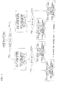
FIG. 3 is a diagram showing a method for designing an outer surface smooth length of a tubular member of a nuclear power plant according to an embodiment of the present invention. -
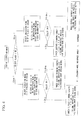
FIG. 4 is a diagram showing a method for designing an inner surface smooth length of a tubular member of a nuclear power plant according to an embodiment of the present invention. -
FIG. 5 is a diagram showing a state in which ultrasonic inspection is being performed with an R-shaped probe. -
FIG. 6 is a diagram showing a nuclear reactor pressure vessel (nuclear power plant). -
FIG. 7A and FIG. 7B are cross-sectional views both showing tubular members (welded portion) of a conventional nuclear power plant. - Hereunder, is a description of a pipeline construction method, tubular members, and a nuclear power plant, according to an embodiment of the present invention, with reference to
FIG. 1 to FIG. 4 , andFIG. 6 . Here, in the present embodiment, the description is given assuming that the tubular members are tubular members are joined by butt welding to form a pipeline R of anuclear plant 1. - With regard to the
tubular members FIG. 1 andFIG. 2 , thinning processing is performed on theinner surfaces 4 on the joinedend inner surfaces 4 of thetubular members inner surfaces 4 on the joinedend tubular members inner surface 4 which extends along the axis O1 direction from thejoined ends tapered surface 6 which connects between this smooth section and the inside of theinner surface 4 which has not been thinning processed. - Furthermore, in these
tubular members tapered surface 6 is formed not exceeding a fixed angle so that mode changes in the sound waves at the time of inner surface reflection are unlikely to occur. - Moreover, in the present embodiment, the
tubular members outer surfaces 5 that extend along the axis O1 direction from the joinedends inner surfaces 4 that extend along the axis O1 direction from the joinedends - More specifically, in the present embodiment, the usage conditions of the pipeline R are set according to
class 1 and class 2 (class 1 equipment andclass 2 equipment), in which the structures, the systems, and the equipment of thenuclear power plant 1 are classified according to the importance of their safety features.Class 1 represents the equipment (vessels, pipes, pumps, and values) and the like that constitute the nuclear reactor coolant pressure boundary. The pair oftubular members class 1 that are joined by butt welding are for example the nozzle provide on the nuclearreactor pressure vessel 1 and the pipeline that is joined to this nozzle. Furthermore,class 2 represents the equipment (vessel, pipes, pumps, valves) and the like for which the importance of the safety features is lower thanclass 1. - Moreover, in the present embodiment, the conditions for ultrasonic inspection of the welded portion M, which are determined by the usage conditions of such a pipeline R, are the areas of inspection prescribed by the "Standards for Nuclear Power Plants:
- Maintenance Standards" mentioned above. That is to say, under the conditions of
class 1, as shown inFIG. 1 , the entire plate thickness t from theinner surface 4 to theouter surface 5 of the welded portion M is made the flaw inspection area S, and under the conditions ofclass 2, as shown inFIG. 2 , a plate thickness area of 1/3 of the designed plate thickness t from theinner surface 4 of the welded portion M is made the flaw inspection area S. - Then, based on such conditions for ultrasonic inspection of the welded portion M, at the time of setting the smooth length of the outer surface 5 (in the design method for the smooth length of the outer surface 5), as shown in
FIG. 3 , selection betweenclass 1 andclass 2 is performed, and in the selected class, selection is made of an inspection menu to be utilized in the design. - At this time, in a case where
class 1 is selected, an inspection menu is Selected so that in the ultrasonic inspection, 2tan 0 at the time of a 1-skip flaw detection, and tan θ at the time of a 0.5-skip flaw detection, become a maximum. On the other hand, in a case whereclass 2 is selected, an inspection menu is selected so that in the ultrasonic inspection, (4/3) tan θ at the time of a 1-skip flaw detection, and tan θ at the time of a 0.5-skip flaw detection, become a maximum. - Here, θ represents the ultrasonic wave incidence angle. Furthermore, 1-skip in ultrasonic inspection means that the ultrasonic waves are delivered to the flaw inspection area S (welded portion M) of the inspected site by entering from the outer surface 5 (end face) of the
tubular members inner surface 4, and 0.5-skip means that the ultrasonic waves are delivered directly to the flaw inspection area S (welded portion M) of the inspected site, by entering from theouter surface 5 of thetubular members - Next, the skip selection is performed. In a case where
class 1 is selected and 1-skip is selected, the outer surface smooth length L1 (mm) is calculated by formula (1), and in a case where class is selected and 0.5-skip is selected, the outer surface smooth length L2 (mm) is calculated by formula (2). Furthermore, in a case whereclass 2 is selected and 1-skip is selected, the outer surface smooth length L3 (mm) is calculated by formula (3), and in a case whereclass 2 is selected and 0.5-skip is selected, the outer surface smooth length L4 (mm) is calculated by formula (4). Here t (mm) represents the thickness (design plate thickness) of the tubular member. -

-

-

-

- By so doing, it is possible to provide a method that prescribes the outer surface smooth lengths L1 to L4 with respect to a variety of combinations of the plate thickness t and the ultrasonic wave incidence angle θ.
- Furthermore, at this time, it is desirable to use the axial length H of the
probe 7 in the calculation of the (probe play), the (probe individual difference), and the (scanning allowance). For example, the probe axial length is made H (mm), and the (probe play) = H/2, the (probe individual difference) = H/2, and the (scanning allowance) = H/2. As a result, it is possible to provide a simple and valid prescription method for the (probe play), the (probe individual difference), and the (scanning allowance). - On the other hand, at the time of setting the inner surface smooth length (length of the inner surface thinning) based on the conditions of the ultrasonic inspection of the welded portion mentioned above (design method for the inner surface smooth length), then as shown in
FIG. 4 ,class 1 orclass 2 is selected, and the inspection menu in the selected class utilized in the design is selected. - At this time, irrespective of whether
class 1 orclass 2 is selected, as long as there is a 1-skip in the inspection menu, the inspection menu in which the ultrasonic wave incidence angle θ becomes a maximum is selected. - Next, the skip selection is performed, In a case where
class 1 is selected and 1-skip is selected, the inner surface smooth length L5 (mm) is calculated by formula (5), and in a case whereclass 1 is selected and 0.5-skip is selected, the inner surface smooth length L6 (mm) is calculated by formula (6). Furthermore, in a case whereclass 2 is selected and 1-skip is selected, the inner surface smooth length L7 (mm) is calculated by formula (7), and in a case whereclass 2 is selected and 0.5-skip is selected, the inner surface smooth length L8 (mm) is calculated by formula (8). -

-

-

-

- As a result, it is possible to provide a method that prescribes the inner surface smooth lengths L5 to L8 with respect to a variety of combinations of the plate thickness t and the ultrasonic wave incidence angle θ.
- Furthermore, at this time, it is desirable to make the ultrasonic wave spread with the size of the oscillator of the
probe 7.
By so doing, it is possible to provide a valid and a simple index value for the ultrasonic wave spread width. - In the present embodiment, as described above, the
tubular members tubular members - At this time, the
tubular members probe 7 transmitting ultrasonic waves on theouter surfaces 5 of thetubular members class 1, as shown inFIG. 1 , a flaw inspection area S of the entire plate thickness t from theinner surface 4 to theouter surface 5 of the welded portion M can be inspected, and forclass 2, as shown inFIG. 2 , a flaw inspection area S of a plate thickness area of 1/3 of the designed plate thickness t from theinner surface 4 of the welded portion M can be inspected. - At a result, in the pipeline R construction method, the
tubular members tubular members 10 and I can be welded to each other in the tubular member welding step, such that the conditions for the ultrasonic inspection of the welded portion M. which are determined by the usage conditions of the pipeline R, can be satisfied with certainty. - Furthermore, at the time of executing the ultrasonic inspection on the welded portion M in the welded portion inspection step, since the outer surface smooth lengths L1 to L4 of the
tubular members probe 7 can be scanned on theouter surfaces 5 of thetubular members - Moreover, at the time of executing the ultrasonic inspection on the welded portion M, in addition to the outer surface smooth lengths L1 to L4 of the
tubular members - Therefore, according to the pipeline R construction method, the
tubular members tubular members - The foregoing has described an embodiment of the pipeline construction method, the tabular members, and the nuclear power plant according to the present invention. However the present invention is in no way limited to the embodiment mentioned above, and appropriate changes are possible within a scope that does not depart from the gist thereof.
- For example, as shown in
FIG. 5 , an R-shaped probe furnished with a curved surface may be used, and the (probe play) at the time of the calculation of the outer surface smooth lengths L1 to L4 may be made smaller than H/2. In this case, it becomes possible to achieve a reduction in the necessary outer surface smooth lengths L1 to L4. - Furthermore, in the case of a subject where the inspection is performed by combining a plurality of methods with different ultrasonic wave incidence angles θi and skips, a combination of the following formulas (9) to (12) that gives the largest value may be utilized in designing the outer surface smooth lengths L1 to L4. Here, in the case of
class 1 formula (9) represents a 1-skip inspection and formula (10) represents a 0.5-skip inspection. Furthermore, in the case ofclass 2, formula (11) represents a 1-skip inspection and formula (12) represents a 0.5-skip inspection. In such a manner, even in a case where a plurality of methods is combined, it becomes possible to simply determine the conditions that become the most constraining. -

-

-

-

Claims (6)
- A construction method of a pipeline that forms pipeline by joining tubular members to each other by butt welding, comprising:a tubular member preparation step for preparing a tubular member (10, 11) having a smooth length of an outer surface (5) along an axial direction (O1) from a joined end (10a, 11a), which is set based on conditions of ultrasonic inspection of a welded portion (M), which are determined by usage conditions of said pipeline (R);a tubular member welding step for welding together prepared tubular members (10,11); anda welded portion inspection step for inspecting a welded portion (M) by ultrasonic inspection.
- A construction method of a pipeline according to claim 1, wherein, in said tubular member preparation step there is provide a tubular member (10,11) having said outer surface smooth length, and an inner surface smooth length along an axial direction (O1) from a joined end (10a, 10b), which is set based on conditions of ultrasonic inspection of a welded portion (M), which are determined by usage conditions of said pipeline (R).
- A construction method of a pipeline according to claim 1 or 2, wherein a probe (7) used in said ultrasonic inspection is an R-shaped probe furnished with a curved surface.
- Tubular members (10, 11) that are joined by butt welding to form a pipeline (R), and have a smooth length of an outer surface (5) along an axial direction (O1) from a joined end (10a, 11a) which is set based on conditions of ultrasonic inspection of a welded portion (M), which are determined by usage conditions of said pipeline (R).
- Tubular members according to claim 4, that have said outer surface smooth length, and an inner surface smooth length along an axial direction (O1) from a joined end (10a, 11a) which is set based on conditions of ultrasonic inspection of a welded portion which are determined by usage conditions of pipeline (R).
- A nuclear power plant (1) furnished with a tubular member according to claim 4 or 5 as a nozzle.
Applications Claiming Priority (1)
| Application Number | Priority Date | Filing Date | Title |
|---|---|---|---|
| JP2011002945A JP5737957B2 (en) | 2011-01-11 | 2011-01-11 | Pipeline construction method |
Publications (2)
| Publication Number | Publication Date |
|---|---|
| EP2474982A2 true EP2474982A2 (en) | 2012-07-11 |
| EP2474982A3 EP2474982A3 (en) | 2014-12-24 |
Family
ID=45470432
Family Applications (1)
| Application Number | Title | Priority Date | Filing Date |
|---|---|---|---|
| EP12150369.2A Withdrawn EP2474982A3 (en) | 2011-01-11 | 2012-01-06 | Construction method, tubular member, and nuclear power plant |
Country Status (3)
| Country | Link |
|---|---|
| US (2) | US20120177165A1 (en) |
| EP (1) | EP2474982A3 (en) |
| JP (1) | JP5737957B2 (en) |
Families Citing this family (3)
| Publication number | Priority date | Publication date | Assignee | Title |
|---|---|---|---|---|
| US11767934B2 (en) | 2013-05-23 | 2023-09-26 | Crc-Evans Pipeline International, Inc. | Internally welded pipes |
| US10480862B2 (en) * | 2013-05-23 | 2019-11-19 | Crc-Evans Pipeline International, Inc. | Systems and methods for use in welding pipe segments of a pipeline |
| US11458571B2 (en) | 2016-07-01 | 2022-10-04 | Crc-Evans Pipeline International, Inc. | Systems and methods for use in welding pipe segments of a pipeline |
Citations (1)
| Publication number | Priority date | Publication date | Assignee | Title |
|---|---|---|---|---|
| JP2005221265A (en) | 2004-02-03 | 2005-08-18 | Toshiba Corp | Nuclear power plant equipment inspection method and nuclear power plant equipment inspection system |
Family Cites Families (7)
| Publication number | Priority date | Publication date | Assignee | Title |
|---|---|---|---|---|
| US3929005A (en) * | 1974-08-01 | 1975-12-30 | John K Parkinson | Ultrasonic inspection recess in heat exchanger and nuclear steam generator tubesheets |
| US4160386A (en) * | 1977-06-09 | 1979-07-10 | Southwest Research Institute | Ultrasonic inspection system including apparatus and method for tracking and recording the location of an inspection probe |
| JP3591000B2 (en) * | 1994-09-12 | 2004-11-17 | 石川島播磨重工業株式会社 | Nozzle ultrasonic flaw detector |
| JP3671819B2 (en) * | 2000-07-06 | 2005-07-13 | 住友金属工業株式会社 | Ultrasonic flaw detector for welded steel pipe |
| JP4559931B2 (en) * | 2005-08-12 | 2010-10-13 | 日立Geニュークリア・エナジー株式会社 | Ultrasonic flaw detection method |
| JP4823046B2 (en) * | 2006-01-16 | 2011-11-24 | 三菱重工業株式会社 | Flaw detection equipment for complex shapes |
| JP4792440B2 (en) * | 2007-09-14 | 2011-10-12 | 株式会社日立製作所 | Pipe weld inspection system |
-
2011
- 2011-01-11 JP JP2011002945A patent/JP5737957B2/en active Active
-
2012
- 2012-01-05 US US13/344,043 patent/US20120177165A1/en not_active Abandoned
- 2012-01-06 EP EP12150369.2A patent/EP2474982A3/en not_active Withdrawn
-
2014
- 2014-11-25 US US14/553,307 patent/US20150131767A1/en not_active Abandoned
Patent Citations (1)
| Publication number | Priority date | Publication date | Assignee | Title |
|---|---|---|---|---|
| JP2005221265A (en) | 2004-02-03 | 2005-08-18 | Toshiba Corp | Nuclear power plant equipment inspection method and nuclear power plant equipment inspection system |
Also Published As
| Publication number | Publication date |
|---|---|
| EP2474982A3 (en) | 2014-12-24 |
| JP5737957B2 (en) | 2015-06-17 |
| US20120177165A1 (en) | 2012-07-12 |
| JP2012145399A (en) | 2012-08-02 |
| US20150131767A1 (en) | 2015-05-14 |
Similar Documents
| Publication | Publication Date | Title |
|---|---|---|
| EP3259587B1 (en) | Method for inspecting a weld seam with ultrasonic phased array | |
| CN103512951B (en) | The method of low frequency ultrasound Guided waves Pipeline butt seam defect | |
| US20170266754A1 (en) | Joint part determination method and joint material manufacturing method | |
| US20150131767A1 (en) | Construction method, tubular member, and nuclear power plant | |
| Anderson et al. | Assessment of crack detection in heavy-walled cast stainless steel piping welds using advanced low-frequency ultrasonic methods | |
| JP5877097B2 (en) | Flaw detection method for clamp type pipe joint | |
| Alobaidi et al. | Enhancing production efficiency of oil and natural gas pipes using microwave technology | |
| Ducharme et al. | Automated Ultrasonic Phased Array Inspection of Fatigue Sensitive Riser Girth Welds with a Weld Overlay Layer of Corrosive Resistant Alloy (CRA) | |
| AIZAWA et al. | Type IV creep voids detection method for high chromium steel welds using ultrasonic backscattered waves | |
| van der Ent et al. | Validation and qualification of IWEX 3D Ultrasonic Imaging for girth weld inspection | |
| KR20110034280A (en) | Method and system for diagnosing defects in generator piping | |
| Anderson et al. | Technical Letter Report-Analysis of Ultrasonic Data on Piping Cracks at Ignalina Nuclear Power Plant Before and After Applying a Mechanical Stress Improvement Process, JCN-N6319, Task 2 | |
| CN112423930B (en) | Repair welding method | |
| JP2003172728A (en) | Ultrasonic detector and ultrasonic inspection method | |
| JP2012002525A (en) | Ultrasound flaw detecting device and control method for the same | |
| JP2019060676A (en) | Oblique angle ultrasonic sound wave inspection soundness evaluation method, and oblique angle ultrasonic sound wave inspection method | |
| Papenfuss | Pigging the “unpiggable”: new technology enables inline inspection and analysis for non-traditional pipelines | |
| Witte et al. | ULTRASONIC GEOMETRY: PROVEN ACCURACY FOR RELIABLE ASSESSMENT | |
| Westwood et al. | Smart pigs and defect assessment codes: completing the circle | |
| Piazza et al. | Integration of Data From Multiple In-Line Inspection Systems to Improve Crack Detection and Characterization | |
| Haas et al. | Phased Array Shot Scenario and Shot Sequence Optimization for Crack Detection Inline Inspection Tools | |
| Rebello et al. | Reliability of the Ultrasonic Technique Applied to Detection of Pipe Weld Defects | |
| Anderson et al. | Ultrasonic Flaw Detection of Cracks and Machined Flawsas Observed through Austenitic Stainless Steel Piping Welds | |
| Leis et al. | Compare-Contrast Analysis of Inspection Data and Failure Predictions versus Burst-Test Outcomes for ERW-Seam Defects | |
| Ushakov et al. | A technique of ultrasonic testing of articles with curvilinear surfaces |
Legal Events
| Date | Code | Title | Description |
|---|---|---|---|
| PUAI | Public reference made under article 153(3) epc to a published international application that has entered the european phase |
Free format text: ORIGINAL CODE: 0009012 |
|
| AK | Designated contracting states |
Kind code of ref document: A2 Designated state(s): AL AT BE BG CH CY CZ DE DK EE ES FI FR GB GR HR HU IE IS IT LI LT LU LV MC MK MT NL NO PL PT RO RS SE SI SK SM TR |
|
| AX | Request for extension of the european patent |
Extension state: BA ME |
|
| PUAL | Search report despatched |
Free format text: ORIGINAL CODE: 0009013 |
|
| AK | Designated contracting states |
Kind code of ref document: A3 Designated state(s): AL AT BE BG CH CY CZ DE DK EE ES FI FR GB GR HR HU IE IS IT LI LT LU LV MC MK MT NL NO PL PT RO RS SE SI SK SM TR |
|
| AX | Request for extension of the european patent |
Extension state: BA ME |
|
| RIC1 | Information provided on ipc code assigned before grant |
Ipc: G01N 29/04 20060101ALI20141119BHEP Ipc: G21C 17/017 20060101AFI20141119BHEP Ipc: B23K 31/00 20060101ALI20141119BHEP Ipc: G01N 29/07 20060101ALI20141119BHEP |
|
| 17P | Request for examination filed |
Effective date: 20150608 |
|
| RBV | Designated contracting states (corrected) |
Designated state(s): AL AT BE BG CH CY CZ DE DK EE ES FI FR GB GR HR HU IE IS IT LI LT LU LV MC MK MT NL NO PL PT RO RS SE SI SK SM TR |
|
| RIC1 | Information provided on ipc code assigned before grant |
Ipc: G21C 17/017 20060101AFI20151208BHEP Ipc: G01N 29/07 20060101ALI20151208BHEP Ipc: G21C 21/00 20060101ALI20151208BHEP Ipc: B23K 31/00 20060101ALI20151208BHEP Ipc: G01N 29/04 20060101ALI20151208BHEP |
|
| 17Q | First examination report despatched |
Effective date: 20160203 |
|
| STAA | Information on the status of an ep patent application or granted ep patent |
Free format text: STATUS: THE APPLICATION IS DEEMED TO BE WITHDRAWN |
|
| 18D | Application deemed to be withdrawn |
Effective date: 20160614 |