EP2474942A2 - Device and method for mounting a wireless electronic component to a surface - Google Patents
Device and method for mounting a wireless electronic component to a surface Download PDFInfo
- Publication number
- EP2474942A2 EP2474942A2 EP12163366A EP12163366A EP2474942A2 EP 2474942 A2 EP2474942 A2 EP 2474942A2 EP 12163366 A EP12163366 A EP 12163366A EP 12163366 A EP12163366 A EP 12163366A EP 2474942 A2 EP2474942 A2 EP 2474942A2
- Authority
- EP
- European Patent Office
- Prior art keywords
- thermoplastic
- housing
- electronic component
- protrusions
- filter
- Prior art date
- Legal status (The legal status is an assumption and is not a legal conclusion. Google has not performed a legal analysis and makes no representation as to the accuracy of the status listed.)
- Granted
Links
Images


Classifications
-
- B—PERFORMING OPERATIONS; TRANSPORTING
- B29—WORKING OF PLASTICS; WORKING OF SUBSTANCES IN A PLASTIC STATE IN GENERAL
- B29C—SHAPING OR JOINING OF PLASTICS; SHAPING OF MATERIAL IN A PLASTIC STATE, NOT OTHERWISE PROVIDED FOR; AFTER-TREATMENT OF THE SHAPED PRODUCTS, e.g. REPAIRING
- B29C66/00—General aspects of processes or apparatus for joining preformed parts
- B29C66/40—General aspects of joining substantially flat articles, e.g. plates, sheets or web-like materials; Making flat seams in tubular or hollow articles; Joining single elements to substantially flat surfaces
- B29C66/47—Joining single elements to sheets, plates or other substantially flat surfaces
- B29C66/474—Joining single elements to sheets, plates or other substantially flat surfaces said single elements being substantially non-flat
-
- B—PERFORMING OPERATIONS; TRANSPORTING
- B29—WORKING OF PLASTICS; WORKING OF SUBSTANCES IN A PLASTIC STATE IN GENERAL
- B29C—SHAPING OR JOINING OF PLASTICS; SHAPING OF MATERIAL IN A PLASTIC STATE, NOT OTHERWISE PROVIDED FOR; AFTER-TREATMENT OF THE SHAPED PRODUCTS, e.g. REPAIRING
- B29C65/00—Joining or sealing of preformed parts, e.g. welding of plastics materials; Apparatus therefor
- B29C65/02—Joining or sealing of preformed parts, e.g. welding of plastics materials; Apparatus therefor by heating, with or without pressure
-
- B—PERFORMING OPERATIONS; TRANSPORTING
- B29—WORKING OF PLASTICS; WORKING OF SUBSTANCES IN A PLASTIC STATE IN GENERAL
- B29C—SHAPING OR JOINING OF PLASTICS; SHAPING OF MATERIAL IN A PLASTIC STATE, NOT OTHERWISE PROVIDED FOR; AFTER-TREATMENT OF THE SHAPED PRODUCTS, e.g. REPAIRING
- B29C66/00—General aspects of processes or apparatus for joining preformed parts
- B29C66/01—General aspects dealing with the joint area or with the area to be joined
- B29C66/05—Particular design of joint configurations
- B29C66/10—Particular design of joint configurations particular design of the joint cross-sections
- B29C66/11—Joint cross-sections comprising a single joint-segment, i.e. one of the parts to be joined comprising a single joint-segment in the joint cross-section
- B29C66/112—Single lapped joints
-
- B—PERFORMING OPERATIONS; TRANSPORTING
- B29—WORKING OF PLASTICS; WORKING OF SUBSTANCES IN A PLASTIC STATE IN GENERAL
- B29C—SHAPING OR JOINING OF PLASTICS; SHAPING OF MATERIAL IN A PLASTIC STATE, NOT OTHERWISE PROVIDED FOR; AFTER-TREATMENT OF THE SHAPED PRODUCTS, e.g. REPAIRING
- B29C66/00—General aspects of processes or apparatus for joining preformed parts
- B29C66/01—General aspects dealing with the joint area or with the area to be joined
- B29C66/05—Particular design of joint configurations
- B29C66/10—Particular design of joint configurations particular design of the joint cross-sections
- B29C66/11—Joint cross-sections comprising a single joint-segment, i.e. one of the parts to be joined comprising a single joint-segment in the joint cross-section
- B29C66/112—Single lapped joints
- B29C66/1122—Single lap to lap joints, i.e. overlap joints
-
- B—PERFORMING OPERATIONS; TRANSPORTING
- B29—WORKING OF PLASTICS; WORKING OF SUBSTANCES IN A PLASTIC STATE IN GENERAL
- B29C—SHAPING OR JOINING OF PLASTICS; SHAPING OF MATERIAL IN A PLASTIC STATE, NOT OTHERWISE PROVIDED FOR; AFTER-TREATMENT OF THE SHAPED PRODUCTS, e.g. REPAIRING
- B29C66/00—General aspects of processes or apparatus for joining preformed parts
- B29C66/01—General aspects dealing with the joint area or with the area to be joined
- B29C66/05—Particular design of joint configurations
- B29C66/10—Particular design of joint configurations particular design of the joint cross-sections
- B29C66/11—Joint cross-sections comprising a single joint-segment, i.e. one of the parts to be joined comprising a single joint-segment in the joint cross-section
- B29C66/114—Single butt joints
-
- B—PERFORMING OPERATIONS; TRANSPORTING
- B29—WORKING OF PLASTICS; WORKING OF SUBSTANCES IN A PLASTIC STATE IN GENERAL
- B29C—SHAPING OR JOINING OF PLASTICS; SHAPING OF MATERIAL IN A PLASTIC STATE, NOT OTHERWISE PROVIDED FOR; AFTER-TREATMENT OF THE SHAPED PRODUCTS, e.g. REPAIRING
- B29C66/00—General aspects of processes or apparatus for joining preformed parts
- B29C66/01—General aspects dealing with the joint area or with the area to be joined
- B29C66/05—Particular design of joint configurations
- B29C66/20—Particular design of joint configurations particular design of the joint lines, e.g. of the weld lines
- B29C66/24—Particular design of joint configurations particular design of the joint lines, e.g. of the weld lines said joint lines being closed or non-straight
- B29C66/242—Particular design of joint configurations particular design of the joint lines, e.g. of the weld lines said joint lines being closed or non-straight said joint lines being closed, i.e. forming closed contours
- B29C66/2424—Particular design of joint configurations particular design of the joint lines, e.g. of the weld lines said joint lines being closed or non-straight said joint lines being closed, i.e. forming closed contours being a closed polygonal chain
- B29C66/24243—Particular design of joint configurations particular design of the joint lines, e.g. of the weld lines said joint lines being closed or non-straight said joint lines being closed, i.e. forming closed contours being a closed polygonal chain forming a quadrilateral
- B29C66/24244—Particular design of joint configurations particular design of the joint lines, e.g. of the weld lines said joint lines being closed or non-straight said joint lines being closed, i.e. forming closed contours being a closed polygonal chain forming a quadrilateral forming a rectangle
-
- B—PERFORMING OPERATIONS; TRANSPORTING
- B29—WORKING OF PLASTICS; WORKING OF SUBSTANCES IN A PLASTIC STATE IN GENERAL
- B29C—SHAPING OR JOINING OF PLASTICS; SHAPING OF MATERIAL IN A PLASTIC STATE, NOT OTHERWISE PROVIDED FOR; AFTER-TREATMENT OF THE SHAPED PRODUCTS, e.g. REPAIRING
- B29C66/00—General aspects of processes or apparatus for joining preformed parts
- B29C66/40—General aspects of joining substantially flat articles, e.g. plates, sheets or web-like materials; Making flat seams in tubular or hollow articles; Joining single elements to substantially flat surfaces
- B29C66/47—Joining single elements to sheets, plates or other substantially flat surfaces
-
- B—PERFORMING OPERATIONS; TRANSPORTING
- B29—WORKING OF PLASTICS; WORKING OF SUBSTANCES IN A PLASTIC STATE IN GENERAL
- B29C—SHAPING OR JOINING OF PLASTICS; SHAPING OF MATERIAL IN A PLASTIC STATE, NOT OTHERWISE PROVIDED FOR; AFTER-TREATMENT OF THE SHAPED PRODUCTS, e.g. REPAIRING
- B29C66/00—General aspects of processes or apparatus for joining preformed parts
- B29C66/40—General aspects of joining substantially flat articles, e.g. plates, sheets or web-like materials; Making flat seams in tubular or hollow articles; Joining single elements to substantially flat surfaces
- B29C66/47—Joining single elements to sheets, plates or other substantially flat surfaces
- B29C66/472—Joining single elements to sheets, plates or other substantially flat surfaces said single elements being substantially flat
-
- B—PERFORMING OPERATIONS; TRANSPORTING
- B29—WORKING OF PLASTICS; WORKING OF SUBSTANCES IN A PLASTIC STATE IN GENERAL
- B29C—SHAPING OR JOINING OF PLASTICS; SHAPING OF MATERIAL IN A PLASTIC STATE, NOT OTHERWISE PROVIDED FOR; AFTER-TREATMENT OF THE SHAPED PRODUCTS, e.g. REPAIRING
- B29C66/00—General aspects of processes or apparatus for joining preformed parts
- B29C66/50—General aspects of joining tubular articles; General aspects of joining long products, i.e. bars or profiled elements; General aspects of joining single elements to tubular articles, hollow articles or bars; General aspects of joining several hollow-preforms to form hollow or tubular articles
- B29C66/51—Joining tubular articles, profiled elements or bars; Joining single elements to tubular articles, hollow articles or bars; Joining several hollow-preforms to form hollow or tubular articles
- B29C66/53—Joining single elements to tubular articles, hollow articles or bars
- B29C66/534—Joining single elements to open ends of tubular or hollow articles or to the ends of bars
- B29C66/5346—Joining single elements to open ends of tubular or hollow articles or to the ends of bars said single elements being substantially flat
- B29C66/53461—Joining single elements to open ends of tubular or hollow articles or to the ends of bars said single elements being substantially flat joining substantially flat covers and/or substantially flat bottoms to open ends of container bodies
-
- B—PERFORMING OPERATIONS; TRANSPORTING
- B29—WORKING OF PLASTICS; WORKING OF SUBSTANCES IN A PLASTIC STATE IN GENERAL
- B29C—SHAPING OR JOINING OF PLASTICS; SHAPING OF MATERIAL IN A PLASTIC STATE, NOT OTHERWISE PROVIDED FOR; AFTER-TREATMENT OF THE SHAPED PRODUCTS, e.g. REPAIRING
- B29C66/00—General aspects of processes or apparatus for joining preformed parts
- B29C66/50—General aspects of joining tubular articles; General aspects of joining long products, i.e. bars or profiled elements; General aspects of joining single elements to tubular articles, hollow articles or bars; General aspects of joining several hollow-preforms to form hollow or tubular articles
- B29C66/61—Joining from or joining on the inside
-
- B—PERFORMING OPERATIONS; TRANSPORTING
- B29—WORKING OF PLASTICS; WORKING OF SUBSTANCES IN A PLASTIC STATE IN GENERAL
- B29C—SHAPING OR JOINING OF PLASTICS; SHAPING OF MATERIAL IN A PLASTIC STATE, NOT OTHERWISE PROVIDED FOR; AFTER-TREATMENT OF THE SHAPED PRODUCTS, e.g. REPAIRING
- B29C70/00—Shaping composites, i.e. plastics material comprising reinforcements, fillers or preformed parts, e.g. inserts
- B29C70/68—Shaping composites, i.e. plastics material comprising reinforcements, fillers or preformed parts, e.g. inserts by incorporating or moulding on preformed parts, e.g. inserts or layers, e.g. foam blocks
- B29C70/70—Completely encapsulating inserts
-
- B—PERFORMING OPERATIONS; TRANSPORTING
- B29—WORKING OF PLASTICS; WORKING OF SUBSTANCES IN A PLASTIC STATE IN GENERAL
- B29C—SHAPING OR JOINING OF PLASTICS; SHAPING OF MATERIAL IN A PLASTIC STATE, NOT OTHERWISE PROVIDED FOR; AFTER-TREATMENT OF THE SHAPED PRODUCTS, e.g. REPAIRING
- B29C70/00—Shaping composites, i.e. plastics material comprising reinforcements, fillers or preformed parts, e.g. inserts
- B29C70/68—Shaping composites, i.e. plastics material comprising reinforcements, fillers or preformed parts, e.g. inserts by incorporating or moulding on preformed parts, e.g. inserts or layers, e.g. foam blocks
- B29C70/74—Moulding material on a relatively small portion of the preformed part, e.g. outsert moulding
-
- G—PHYSICS
- G06—COMPUTING OR CALCULATING; COUNTING
- G06K—GRAPHICAL DATA READING; PRESENTATION OF DATA; RECORD CARRIERS; HANDLING RECORD CARRIERS
- G06K19/00—Record carriers for use with machines and with at least a part designed to carry digital markings
- G06K19/06—Record carriers for use with machines and with at least a part designed to carry digital markings characterised by the kind of the digital marking, e.g. shape, nature, code
- G06K19/067—Record carriers with conductive marks, printed circuits or semiconductor circuit elements, e.g. credit or identity cards also with resonating or responding marks without active components
- G06K19/07—Record carriers with conductive marks, printed circuits or semiconductor circuit elements, e.g. credit or identity cards also with resonating or responding marks without active components with integrated circuit chips
- G06K19/077—Constructional details, e.g. mounting of circuits in the carrier
- G06K19/07749—Constructional details, e.g. mounting of circuits in the carrier the record carrier being capable of non-contact communication, e.g. constructional details of the antenna of a non-contact smart card
- G06K19/07758—Constructional details, e.g. mounting of circuits in the carrier the record carrier being capable of non-contact communication, e.g. constructional details of the antenna of a non-contact smart card arrangements for adhering the record carrier to further objects or living beings, functioning as an identification tag
-
- B—PERFORMING OPERATIONS; TRANSPORTING
- B29—WORKING OF PLASTICS; WORKING OF SUBSTANCES IN A PLASTIC STATE IN GENERAL
- B29C—SHAPING OR JOINING OF PLASTICS; SHAPING OF MATERIAL IN A PLASTIC STATE, NOT OTHERWISE PROVIDED FOR; AFTER-TREATMENT OF THE SHAPED PRODUCTS, e.g. REPAIRING
- B29C65/00—Joining or sealing of preformed parts, e.g. welding of plastics materials; Apparatus therefor
- B29C65/02—Joining or sealing of preformed parts, e.g. welding of plastics materials; Apparatus therefor by heating, with or without pressure
- B29C65/06—Joining or sealing of preformed parts, e.g. welding of plastics materials; Apparatus therefor by heating, with or without pressure using friction, e.g. spin welding
-
- B—PERFORMING OPERATIONS; TRANSPORTING
- B29—WORKING OF PLASTICS; WORKING OF SUBSTANCES IN A PLASTIC STATE IN GENERAL
- B29C—SHAPING OR JOINING OF PLASTICS; SHAPING OF MATERIAL IN A PLASTIC STATE, NOT OTHERWISE PROVIDED FOR; AFTER-TREATMENT OF THE SHAPED PRODUCTS, e.g. REPAIRING
- B29C65/00—Joining or sealing of preformed parts, e.g. welding of plastics materials; Apparatus therefor
- B29C65/02—Joining or sealing of preformed parts, e.g. welding of plastics materials; Apparatus therefor by heating, with or without pressure
- B29C65/08—Joining or sealing of preformed parts, e.g. welding of plastics materials; Apparatus therefor by heating, with or without pressure using ultrasonic vibrations
-
- B—PERFORMING OPERATIONS; TRANSPORTING
- B29—WORKING OF PLASTICS; WORKING OF SUBSTANCES IN A PLASTIC STATE IN GENERAL
- B29C—SHAPING OR JOINING OF PLASTICS; SHAPING OF MATERIAL IN A PLASTIC STATE, NOT OTHERWISE PROVIDED FOR; AFTER-TREATMENT OF THE SHAPED PRODUCTS, e.g. REPAIRING
- B29C65/00—Joining or sealing of preformed parts, e.g. welding of plastics materials; Apparatus therefor
- B29C65/02—Joining or sealing of preformed parts, e.g. welding of plastics materials; Apparatus therefor by heating, with or without pressure
- B29C65/14—Joining or sealing of preformed parts, e.g. welding of plastics materials; Apparatus therefor by heating, with or without pressure using wave energy, i.e. electromagnetic radiation, or particle radiation
-
- B—PERFORMING OPERATIONS; TRANSPORTING
- B29—WORKING OF PLASTICS; WORKING OF SUBSTANCES IN A PLASTIC STATE IN GENERAL
- B29C—SHAPING OR JOINING OF PLASTICS; SHAPING OF MATERIAL IN A PLASTIC STATE, NOT OTHERWISE PROVIDED FOR; AFTER-TREATMENT OF THE SHAPED PRODUCTS, e.g. REPAIRING
- B29C66/00—General aspects of processes or apparatus for joining preformed parts
- B29C66/01—General aspects dealing with the joint area or with the area to be joined
- B29C66/05—Particular design of joint configurations
- B29C66/302—Particular design of joint configurations the area to be joined comprising melt initiators
- B29C66/3022—Particular design of joint configurations the area to be joined comprising melt initiators said melt initiators being integral with at least one of the parts to be joined
- B29C66/30221—Particular design of joint configurations the area to be joined comprising melt initiators said melt initiators being integral with at least one of the parts to be joined said melt initiators being point-like
-
- B—PERFORMING OPERATIONS; TRANSPORTING
- B29—WORKING OF PLASTICS; WORKING OF SUBSTANCES IN A PLASTIC STATE IN GENERAL
- B29C—SHAPING OR JOINING OF PLASTICS; SHAPING OF MATERIAL IN A PLASTIC STATE, NOT OTHERWISE PROVIDED FOR; AFTER-TREATMENT OF THE SHAPED PRODUCTS, e.g. REPAIRING
- B29C66/00—General aspects of processes or apparatus for joining preformed parts
- B29C66/01—General aspects dealing with the joint area or with the area to be joined
- B29C66/05—Particular design of joint configurations
- B29C66/302—Particular design of joint configurations the area to be joined comprising melt initiators
- B29C66/3022—Particular design of joint configurations the area to be joined comprising melt initiators said melt initiators being integral with at least one of the parts to be joined
- B29C66/30223—Particular design of joint configurations the area to be joined comprising melt initiators said melt initiators being integral with at least one of the parts to be joined said melt initiators being rib-like
-
- B—PERFORMING OPERATIONS; TRANSPORTING
- B29—WORKING OF PLASTICS; WORKING OF SUBSTANCES IN A PLASTIC STATE IN GENERAL
- B29C—SHAPING OR JOINING OF PLASTICS; SHAPING OF MATERIAL IN A PLASTIC STATE, NOT OTHERWISE PROVIDED FOR; AFTER-TREATMENT OF THE SHAPED PRODUCTS, e.g. REPAIRING
- B29C66/00—General aspects of processes or apparatus for joining preformed parts
- B29C66/70—General aspects of processes or apparatus for joining preformed parts characterised by the composition, physical properties or the structure of the material of the parts to be joined; Joining with non-plastics material
- B29C66/71—General aspects of processes or apparatus for joining preformed parts characterised by the composition, physical properties or the structure of the material of the parts to be joined; Joining with non-plastics material characterised by the composition of the plastics material of the parts to be joined
-
- Y—GENERAL TAGGING OF NEW TECHNOLOGICAL DEVELOPMENTS; GENERAL TAGGING OF CROSS-SECTIONAL TECHNOLOGIES SPANNING OVER SEVERAL SECTIONS OF THE IPC; TECHNICAL SUBJECTS COVERED BY FORMER USPC CROSS-REFERENCE ART COLLECTIONS [XRACs] AND DIGESTS
- Y10—TECHNICAL SUBJECTS COVERED BY FORMER USPC
- Y10T—TECHNICAL SUBJECTS COVERED BY FORMER US CLASSIFICATION
- Y10T428/00—Stock material or miscellaneous articles
- Y10T428/13—Hollow or container type article [e.g., tube, vase, etc.]
- Y10T428/1352—Polymer or resin containing [i.e., natural or synthetic]
Definitions
- the present invention relates to a product and method of making such a device for encapsulating a wireless component and securing it to a thermoplastic surface of a desired device. More particularly, it relates to a product and method of making such a device for encapsulating a wireless component, such as an RFID tag, and securing it to a thermoplastic surface of a desired device such as a filter or filter capsule, biobag and the like.
- tags such as RFID tags
- RFID tags generally comprise a wireless transponder of some type and an antenna, both of which are mounted to a card or other substrate and generally encapsulated in epoxy or urethane.
- adhesives especially self-stick adhesives.
- adhesives tend to degrade over time and may fail losing the tag and making the entire system unworkable.
- the invention described herein solves this problem by providing an embedded wireless device, such as a RFID tag or Zigbee device, molded into separate housing formed of any thermoplastic material which is compatible with the plastic material of the device to which the tag and housing is to be attached. Subsequently, the tag assembly can be bonded such as by thermal bonding, solvent bonding or adhesive bonding, onto the device as is well known in the industry.
- an embedded wireless device such as a RFID tag or Zigbee device
- one surface of the housing has two or more spaced apart protrusions which center and aid in the attachment of the housing to the device. More preferably, these protrusions act as energy directors that are preferentially melted and used to attach the housing to the device. In addition, these protrusions also form the bulk of the necessary sacrificial material for mechanical attachment.
- a further advantage to this device is that next generation wireless tags will provide customers with real time process information by incorporating sensors into the tag. These tags will need to be in the fluid path and having a universal means of attachment with the fewest new materials of construction will be a great advantage.
- the protrusions are made of thermoplastic and are bonded by an energy based heating such as ultrasonic or vibration welding.
- the protrusions act as energy directors and preferentially absorb the energy at their surfaces adjacent the device against which they have been placed to form a molten thermoplastic plastic bond between the housing and the device.
- the thermoplastic of the housing and the device to which it is attached must be compatible and be capable of bonding to each other.
- they are compatible and one has a lower melting point than the other.
- they are compatible and the protrusions have a lower melting point than the device surface.
- the plastics are the same.
- thermoplastics include but are not limited to polyethylene, polypropylene, EVA copolymers, alpha olefins and metallocene copolymers, PFA, MFA, polycarbonate, vinyl copolymers such as PVC, polyamides such as nylon, polyesters, acrylonitrile-butadienestyrene (ABS), polysulphone, polyethersulphone, polyarylsulphone, polyphenylsulphone, polyacrylonitrile, polyvinylidene fluoride (PVDF), and blends thereof.
- ABS acrylonitrile-butadienestyrene
- PVDF polyvinylidene fluoride
- Figure 1 shows a molded housing 2 with a first closed surface 4 and a recess 6 for the receipt of a wireless device (not shown).
- Figure 2 shows a wireless device 8 in the recess 6 of the housing 2.
- the wireless device is a RFID tag and antenna assembly although it could be any device that uses wireless protocols like Zigbee, Bluetooth, or WUSB.
- the recess is then sealed by a cover 10 preferably formed of the same plastic as the housing 2 although all the cover 10 need be is compatible with the plastic of the housing 2 so it can be sealed in a liquid tight manner to the housing.
- the cover 10 of the housing can be a separately molded or pre-formed piece that is attached to the housing 2 at the rim 12 by heat, ultrasonic or vibration welding, adhesive, solvent bonding and the like. Alternatively and preferably, it can be molded directly over the wireless device and recess such as by injection molding.
- one surface of the device either the first closed surface 4 of the housing 2 or a surface 14 of the cover 10 as shown in Figure 4 (in this instance as shown it is the cover 14) has two or more protrusions 16 formed on it and these protrusions 16 extend away from the surface 14.
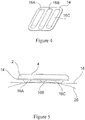
- FIG. 4 In the embodiment of Figure 4 is shown one preferred style in which there are three protrusions 16A, B and C, two of which 16A and C are the same size, shape and other dimensions.
- the third protrusion 16B is of different size and other dimensions, in this embodiment, by height and length.
- This style of device allows one to place the encapsulated wireless component (not shown) in the housing 2 against either a flat 18 or a rounded surface 20 of a device (not shown) to which the wireless component is to be attached, as shown in Figure 5 , and still maintain good contact and center the wireless device and housing on that surface.
- the wireless device in the housing is attached to the surface of the device on which it is mounted by any conventional means such as solvent bonding, adhesives, thermal bonding, such as by ultrasonic or vibration welding or by radiant heat or inductive heat of the plastic of the protrusions and/or the plastic of the device.
- the protrusion are made of thermoplastic and are bonded by an energy based heating such as ultrasonic or vibration welding.
- the protrusions in addition to being stabilizers or centering devices also act as energy directors and preferentially absorb the energy at their surfaces adjacent the device against which they have been placed to form a molten thermoplastic plastic bond between the housing and the device.
- the thermoplastic of the housing and the device to which it is attached must be compatible and be capable of bonding to each other.
- they are compatible and one has a lower melting point than the other.
- they are compatible and the protrusions have a lower melting point than the device surface.
- the plastics are the same.
- the protrusions are further distinguished in that they are the sacrificial material used to mechanically bond to the mating surface. Their dimensions, shape, and spacing can be customized to supply the sufficient amount of sacrificial material necessary to bond. This sacrificial material is the only deformed component of the embodiment, where the electronics and immediately surrounding enclosing material is not directly used in the bonding. Likewise the surface to which it bonds such as the outer surface of a filter housing or filter capsule, or a biobag or a disposable probe, valve or connector is not deformed or distorted.
- thermoplastics include but are not limited to polyethylene, polypropylene, EVA copolymers, alpha olefins and metallocene copolymers, PFA, MFA, polycarbonate, vinyl copolymers such as PVC, polyamides such as nylon, polyesters, acrylonitrile-butadiene styrene (ABS), polysulphone, polyethersulphone, polyarylsulphone, polyphenylsulphone, polyacrylonitrile, polyvinylidene fluoride (PVDF), and blends thereof.
- ABS acrylonitrile-butadiene styrene
- PVDF polyvinylidene fluoride
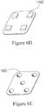
- protrusions 16 Some of which are shown in Figures 6A-D . They may be formed in the shape of a circle 16D of Figure 6A , oval, 16E of Figure 6B , pyramids, 16F of Figure 6C or rectangular or square 16G of Figure 6D . Other shapes and combinations will be obvious to one of ordinary skill in the art. As shown in Figures 6A and D there can be 4 protrusions, while in Figure 6B and C there are only 2. One could also use 5 protrusions as shown in Figure 6E . Other numbers of protrusions can be used and would be obvious to one of ordinary skill in the art.
- the device can be made by several methods.
- a first method is to preform a thermoplastic device formed of a housing having a first closed substantially planar inner surface and a first outer surface and at least one recess for holding the component.
- a wireless component such as an RFID chip and antenna is then placed into the at least one recess. It may simply be laced in loosely or if desired it be adhered in place using an adhesive such as a hot melt thermoplastic, if desired,
- a cover is then overmolded to at least one recess and component with a thermoplastic to encapsulate the component and form a second outer surface of the housing. Either first outer surface or the second outer surface of the housing has two or more spaced apart protrusions extending away from the selected outer surface.
- a second method is to preform a thermoplastic device formed of a housing having a first closed substantially planar inner surface and a first outer surface and at least one recess for holding the component.
- a wireless component such as an RFID chip and antenna is then placed into the at least one recess. It may simply be laced in loosely or if desired it be adhered in place using an adhesive such as a hot melt thermoplastic, if desired.
- a cover is then overmolded to the at least one recess and component with a thermoplastic to encapsulate the component and form a second outer surface of the housing. Either first outer surface or the second outer surface of the housing has two or more spaced apart protrusions extending away from the selected outer surface.
- a thermoplastic assembly such as a cartridge outer housing and at least partially melt the two or more protrusions to form a bond between the thermoplastic assembly and the thermoplastic protrusions of the device.
- a third method is to mold a thermoplastic device formed of a housing having a first closed substantially planar inner surface and a first outer surface and at least one recess for holding the component.
- a wireless component such as an RFID chip and antenna is then placed into the at least one recess while still in the mold.
- a cover is then overmolded to the at least one recess and component with a thermoplastic to encapsulate the component and form a second outer surface of the housing.
- Either first outer surface or the second outer surface of the housing has two or more spaced apart protrusions extending away from the selected outer surface of the device.
- a fourth method is to preform a thermoplastic device formed of a housing having a first closed substantially planar inner surface and a first outer surface and at least one recess for holding the component.
- a wireless component such as an RFID chip and antenna is then placed into the at least one recess. It may simply be laced in loosely or if desired it be adhered in place using an adhesive such as a hot melt thermoplastic, if desired.
- a preformed cover is then placed over the at least one recess and component with a thermoplastic and bonded to it by a thermal bond between the housing and cover such as by radiant heat, vibration or ultrasonic welding or by a hot melt adhesive or the like to enclose the component and form a second outer surface of the housing. Either first outer surface or the second outer surface of the housing has two or more spaced apart protrusions extending away from the selected outer surface of the device.
- a fifth method is to preform a thermoplastic device formed of a housing having a first closed substantially planar inner surface and a first outer surface and at least one recess for holding the component.
- a wireless component such as an RFID chip and antenna is then placed into the at least one recess. It may simply be laced in loosely or if desired it be adhered in place using an adhesive such as a hot melt thermoplastic, if desired.
- a preformed cover is then placed over the at least one recess and component with a thermoplastic and the housing and cover are overmolded to bond the cover and housing together and to enclose the component and form a second outer surface of the housing. Either first outer surface or the second outer surface of the housing has two or more spaced apart protrusions extending away from the selected outer surface of the device.
- a wireless device in this example a RFID tag formed of read/write chip and an antenna, available from Tagsys S.A. of France as catalog item ArioTM SM-ISO RFID tag was selected for this example.
- the wireless device had dimensions of 14 mm wide by 14 mm long and 2 mm high.
- a housing having a cavity with inner cavity dimensions slightly larger than the dimensions of the wireless device was formed of polypropylene.
- the wireless device was tested before insertion into the housing by reading the device with a handheld reader available from Tagsys.
- a cover was formed over and into the cavity of the housing to encapsulate the wireless device within the cavity by an injection molding machine.
- the outer surface of the housing opposite the cavity opening contained three projections in the form of rounded rectangular shapes similar to those shown in Figure 4 .
- the housing was placed against a thermoplastic (polypropylene) outer surface of a SHF filter available from Millipore Corporation of Billerica, Massachusetts and bonded to the outer surface of the filter by heating the projections and the housing with standard vibration thermal welder for a period of approximately 1 minutes while applying pressure between the two. The vibration was then stopped, the filter and housing allowed to cool and the wireless device was then tested and found to be capable of both reading and writing information.
- a thermoplastic polypropylene
Landscapes
- Engineering & Computer Science (AREA)
- Mechanical Engineering (AREA)
- Chemical & Material Sciences (AREA)
- Composite Materials (AREA)
- Computer Hardware Design (AREA)
- Microelectronics & Electronic Packaging (AREA)
- Physics & Mathematics (AREA)
- General Physics & Mathematics (AREA)
- Theoretical Computer Science (AREA)
- Lining Or Joining Of Plastics Or The Like (AREA)
- Near-Field Transmission Systems (AREA)
- Casings For Electric Apparatus (AREA)
- Encapsulation Of And Coatings For Semiconductor Or Solid State Devices (AREA)
Abstract
Description
- This application claims the benefit of
U.S. Provisional Application No. 601873,712 filed December 8, 2006 which is hereby incorporated by reference in it's entirety. - The present invention relates to a product and method of making such a device for encapsulating a wireless component and securing it to a thermoplastic surface of a desired device. More particularly, it relates to a product and method of making such a device for encapsulating a wireless component, such as an RFID tag, and securing it to a thermoplastic surface of a desired device such as a filter or filter capsule, biobag and the like.
- Due to many factors including increased use of manufacturing control and documentation systems, lot traceability, ease of use and item identification, customers require item specific information such as catalog number, lot and serial identification for each filter, media and component used in their process. Currently, techniques such as printing, engraving, laser marking, labeling and bar-coding are used to transfer this information to customers.
- For filter cartridges and other products which are wholly in the fluid path during use, adhesives, inks or any foreign matter are extremely undesirable as they may leach extractable matter into the final product which needs to be identified, quantified and if at too high a level removed. Therefore engraving and laser marking are currently preferred to identify filter cartridges. Unfortunately, this requires the end user to manually read and write down or key in information. This process is subject to error because the engraving is difficult to read on the translucent part. Because of number of times a cartridge needs to be tracked through receiving, multiple uses, storage and disposal, customers are in need of a better way.
- The use of wireless tags such as RFID tags is just being explored as a potential solution. Such tags generally comprise a wireless transponder of some type and an antenna, both of which are mounted to a card or other substrate and generally encapsulated in epoxy or urethane. These tags have been adhered to products through the use of adhesives, especially self-stick adhesives. The issue of adhesives especially in the fluid path remains. Additionally, adhesives tend to degrade over time and may fail losing the tag and making the entire system unworkable.
- Recent advances in in-mold labeling combined with wireless identification technology offer a solution to the problem by eliminating traditional adhesive wireless tags and embedding wireless tags into the device itself, isolating it from the fluid streams. However, the tooling to make such a change is costly and needs to be specific to each part modified with a tag, thus slowing adoption and implementation.
- The invention described herein solves this problem by providing an embedded wireless device, such as a RFID tag or Zigbee device, molded into separate housing formed of any thermoplastic material which is compatible with the plastic material of the device to which the tag and housing is to be attached. Subsequently, the tag assembly can be bonded such as by thermal bonding, solvent bonding or adhesive bonding, onto the device as is well known in the industry.
- Preferably one surface of the housing has two or more spaced apart protrusions which center and aid in the attachment of the housing to the device. More preferably, these protrusions act as energy directors that are preferentially melted and used to attach the housing to the device. In addition, these protrusions also form the bulk of the necessary sacrificial material for mechanical attachment.
- The end result is that the user has to accept no new materials into their processes and can leverage all the benefits of wireless technology on a multitude of products.
- A further advantage to this device is that next generation wireless tags will provide customers with real time process information by incorporating sensors into the tag. These tags will need to be in the fluid path and having a universal means of attachment with the fewest new materials of construction will be a great advantage.
- In one embodiment, the protrusions are made of thermoplastic and are bonded by an energy based heating such as ultrasonic or vibration welding. The protrusions act as energy directors and preferentially absorb the energy at their surfaces adjacent the device against which they have been placed to form a molten thermoplastic plastic bond between the housing and the device. In this embodiment, the thermoplastic of the housing and the device to which it is attached must be compatible and be capable of bonding to each other. In another embodiment, they are compatible and one has a lower melting point than the other. In a further embodiment, they are compatible and the protrusions have a lower melting point than the device surface. In an additional embodiment the plastics are the same.
- Suitable thermoplastics include but are not limited to polyethylene, polypropylene, EVA copolymers, alpha olefins and metallocene copolymers, PFA, MFA, polycarbonate, vinyl copolymers such as PVC, polyamides such as nylon, polyesters, acrylonitrile-butadienestyrene (ABS), polysulphone, polyethersulphone, polyarylsulphone, polyphenylsulphone, polyacrylonitrile, polyvinylidene fluoride (PVDF), and blends thereof.
-
-
Figure 1 shows a portion of the device containing the recess in perspective view. -
Figure 2 shows a portion of the device containing the recess and the wireless component in the recess in perspective view. -
Figure 3 shows one embodiment of the housing with the wireless component in the recess and covered by the second piece of the housing in cross-sectional view. -
Figure 4 shows one preferred embodiment of an outer surface of the device containing the protrusions in perspective view. -
Figure 5 shows one preferred embodiment of the present invention mounted against a surface to which it is to be bonded in perspective view. -
Figure 6A-6E show other embodiments of the outer surface of the device containing the protrusions in perspective view. -
Figure 1 shows amolded housing 2 with a first closedsurface 4 and arecess 6 for the receipt of a wireless device (not shown). -
Figure 2 shows awireless device 8 in therecess 6 of thehousing 2. In this particular example, the wireless device is a RFID tag and antenna assembly although it could be any device that uses wireless protocols like Zigbee, Bluetooth, or WUSB. - The recess is then sealed by a
cover 10 preferably formed of the same plastic as thehousing 2 although all thecover 10 need be is compatible with the plastic of thehousing 2 so it can be sealed in a liquid tight manner to the housing. Thecover 10 of the housing can be a separately molded or pre-formed piece that is attached to thehousing 2 at therim 12 by heat, ultrasonic or vibration welding, adhesive, solvent bonding and the like. Alternatively and preferably, it can be molded directly over the wireless device and recess such as by injection molding. - Preferably, one surface of the device, either the first closed
surface 4 of thehousing 2 or asurface 14 of thecover 10 as shown inFigure 4 (in this instance as shown it is the cover 14) has two or more protrusions 16 formed on it and these protrusions 16 extend away from thesurface 14. - In the embodiment of
Figure 4 is shown one preferred style in which there are threeprotrusions 16A, B and C, two of which 16A and C are the same size, shape and other dimensions. Thethird protrusion 16B is of different size and other dimensions, in this embodiment, by height and length. This style of device allows one to place the encapsulated wireless component (not shown) in thehousing 2 against either a flat 18 or arounded surface 20 of a device (not shown) to which the wireless component is to be attached, as shown inFigure 5 , and still maintain good contact and center the wireless device and housing on that surface. - The wireless device in the housing is attached to the surface of the device on which it is mounted by any conventional means such as solvent bonding, adhesives, thermal bonding, such as by ultrasonic or vibration welding or by radiant heat or inductive heat of the plastic of the protrusions and/or the plastic of the device.
- Preferably, the protrusion are made of thermoplastic and are bonded by an energy based heating such as ultrasonic or vibration welding. The protrusions in addition to being stabilizers or centering devices also act as energy directors and preferentially absorb the energy at their surfaces adjacent the device against which they have been placed to form a molten thermoplastic plastic bond between the housing and the device. In this embodiment, the thermoplastic of the housing and the device to which it is attached must be compatible and be capable of bonding to each other. In another embodiment, they are compatible and one has a lower melting point than the other. In a further embodiment, they are compatible and the protrusions have a lower melting point than the device surface. In an additional embodiment the plastics are the same.
- The protrusions are further distinguished in that they are the sacrificial material used to mechanically bond to the mating surface. Their dimensions, shape, and spacing can be customized to supply the sufficient amount of sacrificial material necessary to bond. This sacrificial material is the only deformed component of the embodiment, where the electronics and immediately surrounding enclosing material is not directly used in the bonding. Likewise the surface to which it bonds such as the outer surface of a filter housing or filter capsule, or a biobag or a disposable probe, valve or connector is not deformed or distorted.
- Suitable thermoplastics include but are not limited to polyethylene, polypropylene, EVA copolymers, alpha olefins and metallocene copolymers, PFA, MFA, polycarbonate, vinyl copolymers such as PVC, polyamides such as nylon, polyesters, acrylonitrile-butadiene styrene (ABS), polysulphone, polyethersulphone, polyarylsulphone, polyphenylsulphone, polyacrylonitrile, polyvinylidene fluoride (PVDF), and blends thereof.
- Other shapes can be used for the protrusions 16 some of which are shown in
Figures 6A-D . They may be formed in the shape of acircle 16D ofFigure 6A , oval, 16E ofFigure 6B , pyramids, 16F ofFigure 6C or rectangular or square 16G ofFigure 6D . Other shapes and combinations will be obvious to one of ordinary skill in the art. As shown inFigures 6A and D there can be 4 protrusions, while inFigure 6B and C there are only 2. One could also use 5 protrusions as shown inFigure 6E . Other numbers of protrusions can be used and would be obvious to one of ordinary skill in the art. - The device can be made by several methods.
- A first method is to preform a thermoplastic device formed of a housing having a first closed substantially planar inner surface and a first outer surface and at least one recess for holding the component. A wireless component, such as an RFID chip and antenna is then placed into the at least one recess. It may simply be laced in loosely or if desired it be adhered in place using an adhesive such as a hot melt thermoplastic, if desired, A cover is then overmolded to at least one recess and component with a thermoplastic to encapsulate the component and form a second outer surface of the housing. Either first outer surface or the second outer surface of the housing has two or more spaced apart protrusions extending away from the selected outer surface.
- A second method is to preform a thermoplastic device formed of a housing having a first closed substantially planar inner surface and a first outer surface and at least one recess for holding the component. A wireless component, such as an RFID chip and antenna is then placed into the at least one recess. It may simply be laced in loosely or if desired it be adhered in place using an adhesive such as a hot melt thermoplastic, if desired. A cover is then overmolded to the at least one recess and component with a thermoplastic to encapsulate the component and form a second outer surface of the housing. Either first outer surface or the second outer surface of the housing has two or more spaced apart protrusions extending away from the selected outer surface. One then holds the two or more protrusions of the device against a thermoplastic assembly such as a cartridge outer housing and at least partially melt the two or more protrusions to form a bond between the thermoplastic assembly and the thermoplastic protrusions of the device.
- A third method is to mold a thermoplastic device formed of a housing having a first closed substantially planar inner surface and a first outer surface and at least one recess for holding the component. A wireless component, such as an RFID chip and antenna is then placed into the at least one recess while still in the mold. A cover is then overmolded to the at least one recess and component with a thermoplastic to encapsulate the component and form a second outer surface of the housing. Either first outer surface or the second outer surface of the housing has two or more spaced apart protrusions extending away from the selected outer surface of the device.
- A fourth method is to preform a thermoplastic device formed of a housing having a first closed substantially planar inner surface and a first outer surface and at least one recess for holding the component. A wireless component, such as an RFID chip and antenna is then placed into the at least one recess. It may simply be laced in loosely or if desired it be adhered in place using an adhesive such as a hot melt thermoplastic, if desired. A preformed cover is then placed over the at least one recess and component with a thermoplastic and bonded to it by a thermal bond between the housing and cover such as by radiant heat, vibration or ultrasonic welding or by a hot melt adhesive or the like to enclose the component and form a second outer surface of the housing. Either first outer surface or the second outer surface of the housing has two or more spaced apart protrusions extending away from the selected outer surface of the device.
- A fifth method is to preform a thermoplastic device formed of a housing having a first closed substantially planar inner surface and a first outer surface and at least one recess for holding the component. A wireless component, such as an RFID chip and antenna is then placed into the at least one recess. It may simply be laced in loosely or if desired it be adhered in place using an adhesive such as a hot melt thermoplastic, if desired. A preformed cover is then placed over the at least one recess and component with a thermoplastic and the housing and cover are overmolded to bond the cover and housing together and to enclose the component and form a second outer surface of the housing. Either first outer surface or the second outer surface of the housing has two or more spaced apart protrusions extending away from the selected outer surface of the device.
- Other methods can also be used as part of the present invention and would be obvious to one of ordinary skill in the art.
- A wireless device, in this example a RFID tag formed of read/write chip and an antenna, available from Tagsys S.A. of France as catalog item Ario™ SM-ISO RFID tag was selected for this example. The wireless device had dimensions of 14 mm wide by 14 mm long and 2 mm high.
- A housing having a cavity with inner cavity dimensions slightly larger than the dimensions of the wireless device was formed of polypropylene.
- The wireless device was tested before insertion into the housing by reading the device with a handheld reader available from Tagsys.
- A cover was formed over and into the cavity of the housing to encapsulate the wireless device within the cavity by an injection molding machine.
- The outer surface of the housing opposite the cavity opening contained three projections in the form of rounded rectangular shapes similar to those shown in
Figure 4 . - The housing was placed against a thermoplastic (polypropylene) outer surface of a SHF filter available from Millipore Corporation of Billerica, Massachusetts and bonded to the outer surface of the filter by heating the projections and the housing with standard vibration thermal welder for a period of approximately 1 minutes while applying pressure between the two. The vibration was then stopped, the filter and housing allowed to cool and the wireless device was then tested and found to be capable of both reading and writing information.
Claims (13)
- A device for mounting a wireless electronic component to a surface comprising:a thermoplastic housing (2) having a first closed substantially planar inner surface and a first outer surface (4) and at least one recess (6) for holding the electronic component (8);a wireless electronic component (8) retained within the recess (6);andan overmolded cover (10) attached to the recess (6) and housing (2) so as to encapsulate the electronic component (8) and form a second outer surface (14) of the housing (2),wherein either the first outer surface (4) or the second outer surface (14) of the housing (2) has two or more spaced apart protrusions (16) extending away from the outer surface (4,14).
- The device for mounting a wireless electronic component of claim 1, wherein the surface to which the device is to be mounted is thermoplastic, and the two or more spaced apart protrusions (16) extending away from the outer surface are adapted to act as centering devices and energy directors for thermally bonding the device to the surface.
- A filter device comprising
a filter cartridge contained within a thermoplastic, housing, the housing having an inlet to an interior of the housing and exterior of the filter cartridge, an outlet attached to an outlet of the filter cartridge in a liquid tight manner, the housing bering formed of a thermoplastic material; and
a device for mounting a wireless electronic component as defined in claim 1 or 2 bonded to the thermoplastic surface of the housing. - A biobag comprising
a bag formed of one or pieces of film and having a central closed off cavity, the bag having one or more inlets and one or more outlets to the cavity in a liquid light manner, the bag being formed of one or more thermoplastic materials; and
a device for mounting a wireless electronic component as defined in claim 1 or 2 bonded to the thermoplastic surface of the bag. - A filter device comprising
a filter cartridge formed of a porous core surrounded by one or more porous filter layers, an outer thermoplastic cage spaced from and surrounding the one or more filters layers, a top closed end cap formed over a first end of the cage, one or more filter layers and core, a second end cap having an opening in line with the core, the second end cap being formed over a second end of the core, one or more filter layers and core, and the cage having a series of inlets to an outer surface of the one or more filter layers and an outlet attached to the opening of the second end cap all in a liquid light manner; and
a device for mounting a wireless electronic component as defined in claim 1 or 2 bonded to the thermoplastic surface of the housing. - A disposable connector assembly comprising
a connector having a first end which can be selectively closed and opened to the environment, a body downstream of the first end having a bore through which fluid may flow when the first end is in an open position, and a second end on a portion of the body downstream from the first end, the second end being attached to a tubing at a first end of the tubing and a second end of the tubing being attached to a device selected from the group consisting of filter capsule, a bag and a second disposable connector, the connector having at least an outer portion formed of a thermoplastic material; and
a device for mounting a wireless electronic component as defined in claim 1 or 2 bonded to the thermoplastic portion of the connector. - A disposable sampling device comprising
a sampling needle having a first end and a second end, a tubing having a first end and a second end, the first end of the tubing being connected to the second end of the needle and the second end of the tubing being connected to one or more thermoplastic sample bags so as to establish a fluid path from the first end of the needle to the one or more sample bags; and
a device for mounting a wireless electronic component as defined in claim 1 or 2 bonded to the thermoplastic surface of the sampling device. - A process for mounting a wireless electronic component to a thermoplastic assembly, comprising the steps of:a) forming a thermoplastic device formed of a housing (2) having a first closed substantially planar inner surface and a first outer surface (4) and at least one recess (6) for holding the electronic component (8);b) placing the electronic component into the at least one recess (6);c) overmolding the at least one recess (6) and electronic component (8) with a thermoplastic to encapsulate the electronic component (8) and form a second outer surface (14) of the housing (2), wherein either the first outer surface (4) or the second outer surface (14) of the housing (2) has two or more spaced apart protrusions (16) extending away from the outer surface (4,14);d) holding the two or more protrusions (16) of the device against the thermoplastic assembly and at least partially melting the two or more protrusions (16) to form a bond between the thermoplastic assembly and the thermoplastic of the device.
- The process of claim 8 wherein the number of protrusions (16) is at least three.
- The process of claim 9 wherein the protrusions (16) act as centering devices and energy directors for thermally bonding the device to the assembly.
- The process of claim 8, 9 or 10 wherein the assembly is selected from the group consisting of a filter cassette, a filter cartridge, a filter housing, a biobag, a sampling device, a valve, a connector, tubing and combinations thereof.
- The process of any one of claims 8 to 11 wherein the protrusions (16) are bonded to the thermoplastic of the assembly through the use of heat generated from a method selected from the group consisting of vibration welding, ultrasonic welding and radiant heat.
- The process of any one of claims 8 to 12 wherein the thermoplastic of the device holding the electronic component and the thermoplastic of the assembly to which it is attached are compatible.
Applications Claiming Priority (2)
| Application Number | Priority Date | Filing Date | Title |
|---|---|---|---|
| US87371206P | 2006-12-08 | 2006-12-08 | |
| EP20070121392 EP1930845B1 (en) | 2006-12-08 | 2007-11-23 | Method and device for mounting a wireless electronic component to a surface |
Related Parent Applications (3)
| Application Number | Title | Priority Date | Filing Date |
|---|---|---|---|
| EP07121392.0 Division | 2007-11-23 | ||
| EP20070121392 Division EP1930845B1 (en) | 2006-12-08 | 2007-11-23 | Method and device for mounting a wireless electronic component to a surface |
| EP20070121392 Division-Into EP1930845B1 (en) | 2006-12-08 | 2007-11-23 | Method and device for mounting a wireless electronic component to a surface |
Publications (3)
| Publication Number | Publication Date |
|---|---|
| EP2474942A2 true EP2474942A2 (en) | 2012-07-11 |
| EP2474942A3 EP2474942A3 (en) | 2012-10-24 |
| EP2474942B1 EP2474942B1 (en) | 2022-08-03 |
Family
ID=39615577
Family Applications (2)
| Application Number | Title | Priority Date | Filing Date |
|---|---|---|---|
| EP12163366.3A Active EP2474942B1 (en) | 2006-12-08 | 2007-11-23 | Device and method for mounting a wireless electronic component to a surface |
| EP20070121392 Active EP1930845B1 (en) | 2006-12-08 | 2007-11-23 | Method and device for mounting a wireless electronic component to a surface |
Family Applications After (1)
| Application Number | Title | Priority Date | Filing Date |
|---|---|---|---|
| EP20070121392 Active EP1930845B1 (en) | 2006-12-08 | 2007-11-23 | Method and device for mounting a wireless electronic component to a surface |
Country Status (6)
| Country | Link |
|---|---|
| US (2) | US7892471B2 (en) |
| EP (2) | EP2474942B1 (en) |
| JP (1) | JP4820356B2 (en) |
| CN (1) | CN101219576B (en) |
| ES (2) | ES2549978T3 (en) |
| SG (2) | SG143219A1 (en) |
Families Citing this family (23)
| Publication number | Priority date | Publication date | Assignee | Title |
|---|---|---|---|---|
| US7892471B2 (en) * | 2006-12-08 | 2011-02-22 | Millipore Corporation | Wireless enabled device |
| GB2454210A (en) * | 2007-10-31 | 2009-05-06 | Intellident Ltd | Radio frequency identification tag enclosure and method of manufacture |
| JP2009225193A (en) * | 2008-03-17 | 2009-10-01 | Fujitsu Ltd | Mobile terminal device |
| CN101513297B (en) * | 2009-02-26 | 2011-08-03 | 上海造币有限公司 | Metal coin stamp embedded with RFID electronic tag and manufacturing technique thereof |
| DE102009014343A1 (en) * | 2009-03-21 | 2010-09-23 | Deutsche Telekom Ag | Method for producing a chip card having a contactless and a contact-type interface |
| TWI398978B (en) * | 2010-06-25 | 2013-06-11 | Simplo Technology Co Ltd | Method for manufacturing battery case |
| US9682335B2 (en) * | 2011-02-24 | 2017-06-20 | Saint-Gobain Performance Plastics Corporation | Modular filter capsule apparatus |
| AU2012255721A1 (en) | 2011-05-17 | 2014-01-09 | Natrix Separations Inc. | Layered tubular membranes for chromatography, and methods of use thereof |
| JPWO2014007342A1 (en) * | 2012-07-06 | 2016-06-02 | 帝人株式会社 | FIBER-REINFORCED COMPOSITE MATERIAL-METHOD FOR PRODUCING METAL MEMBER ASSEMBLY AND FIBER-REINFORCED COMPOSITE MATERIAL USED FOR THE |
| CA2886005C (en) * | 2012-09-24 | 2017-04-11 | Satyatek Sa | Radio frequency identification capsule (rfid) |
| GB201302467D0 (en) * | 2013-02-12 | 2013-03-27 | Bofa Internat Ltd | Filter assemblies |
| US9626620B2 (en) | 2013-06-05 | 2017-04-18 | Haemonetics Corporation | Frangible RFID tag and method of producing same |
| WO2014204844A1 (en) | 2013-06-18 | 2014-12-24 | Haemonetics Corporation | Rfid tag and method of securing same to object |
| US9159017B2 (en) * | 2013-10-18 | 2015-10-13 | William Frick And Company | Passive, metal mount, UHF, RFID tag capable of a long read range |
| CN104091196B (en) * | 2014-08-06 | 2018-05-22 | 朱云晖 | A kind of water-fastness, heat safe RFID label tag and its composite molding technique |
| DE102014117725A1 (en) | 2014-12-02 | 2016-06-02 | Aquis Wasser-Luft-Systeme Gmbh, Lindau, Zweigniederlassung Rebstein | Filter for insertion into a water storage tank of a household appliance, in particular a beverage machine |
| JP6010641B2 (en) * | 2015-01-28 | 2016-10-19 | 富士重工業株式会社 | Resin member and joining method of resin member |
| FR3044561B1 (en) * | 2015-12-08 | 2021-05-14 | Ac Sp Etude & Rech En Hygiene Industrielle | FILTER HOLDER, FILTRATION DEVICE AND METHOD FOR MANUFACTURING A FILTER HOLDER |
| US10286343B2 (en) | 2016-10-28 | 2019-05-14 | Pall Corporation | Filter including RFID tag |
| EP3446861A1 (en) * | 2017-08-21 | 2019-02-27 | Gambro Lundia AB | Method for sealing medical devices |
| CN108100452B (en) * | 2017-11-28 | 2020-12-29 | 苏州良才物流科技股份有限公司 | Take RFID electronic tags's turnover case |
| DE102018213005B3 (en) | 2018-08-03 | 2019-07-25 | Sisto Armaturen S.A. | Membrane with electronic component |
| JP7341226B2 (en) * | 2018-09-26 | 2023-09-08 | カボ デンタル ゲゼルシャフト ミット ベシュレンクテル ハフツング | Dental or surgical handpiece with RFID transponder |
Family Cites Families (26)
| Publication number | Priority date | Publication date | Assignee | Title |
|---|---|---|---|---|
| US3458380A (en) * | 1965-08-26 | 1969-07-29 | Union Carbide Corp | Method of bonding thermoplastics |
| AT332801B (en) | 1972-10-05 | 1976-10-25 | Ralfs Gmbh | RECEIVER |
| US4045350A (en) * | 1975-03-19 | 1977-08-30 | Statni Vyzkumny Ustav Materialu | Filter assembly made of thermoplastic materials |
| US4992166A (en) * | 1988-06-13 | 1991-02-12 | Facet Enterprises, Inc. | Plastic fluid filter and method for manufacturing same |
| US5328597A (en) * | 1992-07-27 | 1994-07-12 | The Clorox Corporation | Electronic monitoring unit for monitoring number of uses of cartridge |
| JPH09240179A (en) * | 1996-03-06 | 1997-09-16 | Shinsei Kagaku Kogyo Kk | Ic card and manufacture of ic card and ic card base |
| JP2002082120A (en) * | 2000-09-06 | 2002-03-22 | Itochu Fine Chemical Corp | Automatic information-readable container for living organism/biological and automatic information reading system |
| US6471853B1 (en) * | 2000-11-22 | 2002-10-29 | Pti Technologies, Inc. | Prognostic health monitoring of fluidic systems using MEMS technology |
| US6533926B2 (en) * | 2001-04-05 | 2003-03-18 | Fleetguard, Inc. | Filter cartridge with concentric circuit rings for data transmission |
| JP2003066301A (en) | 2001-08-29 | 2003-03-05 | Mitsumi Electric Co Ltd | Lens and lens holder joining structure and joining method |
| DE10151270B4 (en) * | 2001-10-17 | 2006-10-26 | Sartorius Ag | System and method for monitoring the integrity of a filter element |
| US6769316B2 (en) * | 2002-06-21 | 2004-08-03 | Rupprecht & Patashnick Company, Inc. | Sampling cartridge for gas sampling apparatus |
| US7252757B2 (en) * | 2002-09-09 | 2007-08-07 | Clarity Filters Llc | Faucet-mounted water filtration device including gate position sensor |
| US7258781B2 (en) * | 2002-09-09 | 2007-08-21 | Clarity Filters Llc | Single-use long-life faucet-mounted water filtration devices |
| DE10328695A1 (en) | 2003-04-17 | 2004-10-28 | Aeg Identifikationssysteme Gmbh | Transponder arrangement with hollow space for transponder and attachment plate to attach transponder to object |
| US20050163667A1 (en) * | 2004-01-26 | 2005-07-28 | Krause Richard J. | Single-use biobags with sendors: DO, pH, CO2 and temperature |
| US7481917B2 (en) * | 2004-03-05 | 2009-01-27 | Hydranautics | Filtration devices with embedded radio frequency identification (RFID) tags |
| AU2005223452B2 (en) * | 2004-03-16 | 2008-05-15 | Newage Industries, Inc. | Process equipment tracking system |
| JP4680540B2 (en) | 2004-06-29 | 2011-05-11 | トッパン・フォームズ株式会社 | Manufacturing method of semiconductor device |
| JP4256320B2 (en) * | 2004-09-28 | 2009-04-22 | ダイキョーニシカワ株式会社 | Bonding structure and bonding method of resin molded body |
| JP2006277524A (en) * | 2005-03-30 | 2006-10-12 | Sato Corp | RFID label and its attaching method |
| DE102004054172A1 (en) * | 2004-11-10 | 2006-05-18 | Hydac Filtertechnik Gmbh | Filter element and associated data transmission device |
| GB0521702D0 (en) | 2005-10-25 | 2005-11-30 | Bryant Keith C | Rfid enabled plastic container |
| US7705733B2 (en) * | 2006-01-06 | 2010-04-27 | Warsaw Orthopedic, Inc. | Coiled RFID tag |
| US7699989B2 (en) * | 2006-10-17 | 2010-04-20 | Millipore Corporation | Powered cartridges and other devices within housings |
| US7892471B2 (en) * | 2006-12-08 | 2011-02-22 | Millipore Corporation | Wireless enabled device |
-
2007
- 2007-11-15 US US11/985,471 patent/US7892471B2/en active Active
- 2007-11-23 EP EP12163366.3A patent/EP2474942B1/en active Active
- 2007-11-23 EP EP20070121392 patent/EP1930845B1/en active Active
- 2007-11-23 ES ES07121392.0T patent/ES2549978T3/en active Active
- 2007-11-23 ES ES12163366T patent/ES2927139T3/en active Active
- 2007-11-30 SG SG200718202-5A patent/SG143219A1/en unknown
- 2007-11-30 SG SG2011072238A patent/SG175585A1/en unknown
- 2007-12-07 CN CN200710164682XA patent/CN101219576B/en not_active Expired - Fee Related
- 2007-12-07 JP JP2007317476A patent/JP4820356B2/en not_active Expired - Fee Related
-
2010
- 2010-10-21 US US12/909,439 patent/US8100585B2/en active Active
Non-Patent Citations (1)
| Title |
|---|
| None |
Also Published As
| Publication number | Publication date |
|---|---|
| SG175585A1 (en) | 2011-11-28 |
| ES2549978T3 (en) | 2015-11-03 |
| EP1930845A3 (en) | 2009-10-14 |
| US20080213135A1 (en) | 2008-09-04 |
| EP2474942B1 (en) | 2022-08-03 |
| CN101219576A (en) | 2008-07-16 |
| EP2474942A3 (en) | 2012-10-24 |
| EP1930845B1 (en) | 2015-05-06 |
| SG143219A1 (en) | 2008-06-27 |
| JP2008226226A (en) | 2008-09-25 |
| US7892471B2 (en) | 2011-02-22 |
| JP4820356B2 (en) | 2011-11-24 |
| CN101219576B (en) | 2011-12-21 |
| US8100585B2 (en) | 2012-01-24 |
| US20110031178A1 (en) | 2011-02-10 |
| ES2927139T3 (en) | 2022-11-02 |
| EP1930845A2 (en) | 2008-06-11 |
Similar Documents
| Publication | Publication Date | Title |
|---|---|---|
| EP1930845B1 (en) | Method and device for mounting a wireless electronic component to a surface | |
| US8710958B2 (en) | Containers having radio frequency identification tags and method of applying radio frequency identification tags to containers | |
| EP2471722B1 (en) | Wireless enabled bags and containers | |
| EP1799610B1 (en) | Coupler with radio frequency identification tag | |
| CN101873885B (en) | Thin film valve device and its controlling apparatus | |
| JP2014531601A5 (en) | ||
| US9862130B2 (en) | Flexible tube comprising an electronic component | |
| EP2348461A1 (en) | RFID tag for high temperature environment | |
| JP5545727B2 (en) | Microtube, and IC chip sealing method in microtube | |
| JP2008079889A (en) | Wireless recognition IC tag enclosed straw | |
| JP2003030599A (en) | Non-contact communication information carrier | |
| JP2007286451A (en) | Identification member and sample container to which the identification member can be attached | |
| MXPA06005790A (en) | Flexible tube comprising an electronic component |
Legal Events
| Date | Code | Title | Description |
|---|---|---|---|
| PUAI | Public reference made under article 153(3) epc to a published international application that has entered the european phase |
Free format text: ORIGINAL CODE: 0009012 |
|
| 17P | Request for examination filed |
Effective date: 20120405 |
|
| AC | Divisional application: reference to earlier application |
Ref document number: 1930845 Country of ref document: EP Kind code of ref document: P |
|
| AK | Designated contracting states |
Kind code of ref document: A2 Designated state(s): AT BE BG CH CY CZ DE DK EE ES FI FR GB GR HU IE IS IT LI LT LU LV MC MT NL PL PT RO SE SI SK TR |
|
| PUAL | Search report despatched |
Free format text: ORIGINAL CODE: 0009013 |
|
| AK | Designated contracting states |
Kind code of ref document: A3 Designated state(s): AT BE BG CH CY CZ DE DK EE ES FI FR GB GR HU IE IS IT LI LT LU LV MC MT NL PL PT RO SE SI SK TR |
|
| RIC1 | Information provided on ipc code assigned before grant |
Ipc: G06K 19/077 20060101AFI20120917BHEP Ipc: B29C 70/74 20060101ALI20120917BHEP Ipc: B29C 70/70 20060101ALI20120917BHEP Ipc: B29C 65/02 20060101ALI20120917BHEP |
|
| 17Q | First examination report despatched |
Effective date: 20151007 |
|
| STAA | Information on the status of an ep patent application or granted ep patent |
Free format text: STATUS: EXAMINATION IS IN PROGRESS |
|
| RAP1 | Party data changed (applicant data changed or rights of an application transferred) |
Owner name: EMD MILLIPORE CORPORATION |
|
| GRAP | Despatch of communication of intention to grant a patent |
Free format text: ORIGINAL CODE: EPIDOSNIGR1 |
|
| STAA | Information on the status of an ep patent application or granted ep patent |
Free format text: STATUS: GRANT OF PATENT IS INTENDED |
|
| RIC1 | Information provided on ipc code assigned before grant |
Ipc: B29C 65/06 20060101ALI20220309BHEP Ipc: B29C 65/14 20060101ALI20220309BHEP Ipc: B29C 65/08 20060101ALI20220309BHEP Ipc: B29C 65/00 20060101ALI20220309BHEP Ipc: B29C 70/74 20060101ALI20220309BHEP Ipc: B29C 70/70 20060101ALI20220309BHEP Ipc: B29C 65/02 20060101ALI20220309BHEP Ipc: G06K 19/077 20060101AFI20220309BHEP |
|
| INTG | Intention to grant announced |
Effective date: 20220323 |
|
| GRAS | Grant fee paid |
Free format text: ORIGINAL CODE: EPIDOSNIGR3 |
|
| GRAA | (expected) grant |
Free format text: ORIGINAL CODE: 0009210 |
|
| STAA | Information on the status of an ep patent application or granted ep patent |
Free format text: STATUS: THE PATENT HAS BEEN GRANTED |
|
| AC | Divisional application: reference to earlier application |
Ref document number: 1930845 Country of ref document: EP Kind code of ref document: P |
|
| AK | Designated contracting states |
Kind code of ref document: B1 Designated state(s): AT BE BG CH CY CZ DE DK EE ES FI FR GB GR HU IE IS IT LI LT LU LV MC MT NL PL PT RO SE SI SK TR |
|
| REG | Reference to a national code |
Ref country code: GB Ref legal event code: FG4D |
|
| REG | Reference to a national code |
Ref country code: AT Ref legal event code: REF Ref document number: 1509340 Country of ref document: AT Kind code of ref document: T Effective date: 20220815 Ref country code: CH Ref legal event code: EP |
|
| REG | Reference to a national code |
Ref country code: DE Ref legal event code: R096 Ref document number: 602007061551 Country of ref document: DE |
|
| REG | Reference to a national code |
Ref country code: IE Ref legal event code: FG4D |
|
| REG | Reference to a national code |
Ref country code: NL Ref legal event code: FP |
|
| REG | Reference to a national code |
Ref country code: ES Ref legal event code: FG2A Ref document number: 2927139 Country of ref document: ES Kind code of ref document: T3 Effective date: 20221102 |
|
| REG | Reference to a national code |
Ref country code: LT Ref legal event code: MG9D |
|
| PG25 | Lapsed in a contracting state [announced via postgrant information from national office to epo] |
Ref country code: SE Free format text: LAPSE BECAUSE OF FAILURE TO SUBMIT A TRANSLATION OF THE DESCRIPTION OR TO PAY THE FEE WITHIN THE PRESCRIBED TIME-LIMIT Effective date: 20220803 Ref country code: PT Free format text: LAPSE BECAUSE OF FAILURE TO SUBMIT A TRANSLATION OF THE DESCRIPTION OR TO PAY THE FEE WITHIN THE PRESCRIBED TIME-LIMIT Effective date: 20221205 Ref country code: LV Free format text: LAPSE BECAUSE OF FAILURE TO SUBMIT A TRANSLATION OF THE DESCRIPTION OR TO PAY THE FEE WITHIN THE PRESCRIBED TIME-LIMIT Effective date: 20220803 Ref country code: LT Free format text: LAPSE BECAUSE OF FAILURE TO SUBMIT A TRANSLATION OF THE DESCRIPTION OR TO PAY THE FEE WITHIN THE PRESCRIBED TIME-LIMIT Effective date: 20220803 Ref country code: FI Free format text: LAPSE BECAUSE OF FAILURE TO SUBMIT A TRANSLATION OF THE DESCRIPTION OR TO PAY THE FEE WITHIN THE PRESCRIBED TIME-LIMIT Effective date: 20220803 |
|
| REG | Reference to a national code |
Ref country code: AT Ref legal event code: MK05 Ref document number: 1509340 Country of ref document: AT Kind code of ref document: T Effective date: 20220803 |
|
| PG25 | Lapsed in a contracting state [announced via postgrant information from national office to epo] |
Ref country code: PL Free format text: LAPSE BECAUSE OF FAILURE TO SUBMIT A TRANSLATION OF THE DESCRIPTION OR TO PAY THE FEE WITHIN THE PRESCRIBED TIME-LIMIT Effective date: 20220803 Ref country code: IS Free format text: LAPSE BECAUSE OF FAILURE TO SUBMIT A TRANSLATION OF THE DESCRIPTION OR TO PAY THE FEE WITHIN THE PRESCRIBED TIME-LIMIT Effective date: 20221203 Ref country code: GR Free format text: LAPSE BECAUSE OF FAILURE TO SUBMIT A TRANSLATION OF THE DESCRIPTION OR TO PAY THE FEE WITHIN THE PRESCRIBED TIME-LIMIT Effective date: 20221104 |
|
| PG25 | Lapsed in a contracting state [announced via postgrant information from national office to epo] |
Ref country code: RO Free format text: LAPSE BECAUSE OF FAILURE TO SUBMIT A TRANSLATION OF THE DESCRIPTION OR TO PAY THE FEE WITHIN THE PRESCRIBED TIME-LIMIT Effective date: 20220803 Ref country code: DK Free format text: LAPSE BECAUSE OF FAILURE TO SUBMIT A TRANSLATION OF THE DESCRIPTION OR TO PAY THE FEE WITHIN THE PRESCRIBED TIME-LIMIT Effective date: 20220803 Ref country code: CZ Free format text: LAPSE BECAUSE OF FAILURE TO SUBMIT A TRANSLATION OF THE DESCRIPTION OR TO PAY THE FEE WITHIN THE PRESCRIBED TIME-LIMIT Effective date: 20220803 Ref country code: AT Free format text: LAPSE BECAUSE OF FAILURE TO SUBMIT A TRANSLATION OF THE DESCRIPTION OR TO PAY THE FEE WITHIN THE PRESCRIBED TIME-LIMIT Effective date: 20220803 |
|
| REG | Reference to a national code |
Ref country code: DE Ref legal event code: R097 Ref document number: 602007061551 Country of ref document: DE |
|
| PG25 | Lapsed in a contracting state [announced via postgrant information from national office to epo] |
Ref country code: SK Free format text: LAPSE BECAUSE OF FAILURE TO SUBMIT A TRANSLATION OF THE DESCRIPTION OR TO PAY THE FEE WITHIN THE PRESCRIBED TIME-LIMIT Effective date: 20220803 Ref country code: EE Free format text: LAPSE BECAUSE OF FAILURE TO SUBMIT A TRANSLATION OF THE DESCRIPTION OR TO PAY THE FEE WITHIN THE PRESCRIBED TIME-LIMIT Effective date: 20220803 |
|
| PLBE | No opposition filed within time limit |
Free format text: ORIGINAL CODE: 0009261 |
|
| STAA | Information on the status of an ep patent application or granted ep patent |
Free format text: STATUS: NO OPPOSITION FILED WITHIN TIME LIMIT |
|
| PG25 | Lapsed in a contracting state [announced via postgrant information from national office to epo] |
Ref country code: MC Free format text: LAPSE BECAUSE OF FAILURE TO SUBMIT A TRANSLATION OF THE DESCRIPTION OR TO PAY THE FEE WITHIN THE PRESCRIBED TIME-LIMIT Effective date: 20220803 |
|
| 26N | No opposition filed |
Effective date: 20230504 |
|
| P01 | Opt-out of the competence of the unified patent court (upc) registered |
Effective date: 20230602 |
|
| PG25 | Lapsed in a contracting state [announced via postgrant information from national office to epo] |
Ref country code: SI Free format text: LAPSE BECAUSE OF FAILURE TO SUBMIT A TRANSLATION OF THE DESCRIPTION OR TO PAY THE FEE WITHIN THE PRESCRIBED TIME-LIMIT Effective date: 20220803 Ref country code: LU Free format text: LAPSE BECAUSE OF NON-PAYMENT OF DUE FEES Effective date: 20221123 |
|
| PGFP | Annual fee paid to national office [announced via postgrant information from national office to epo] |
Ref country code: IE Payment date: 20230912 Year of fee payment: 17 |
|
| PGFP | Annual fee paid to national office [announced via postgrant information from national office to epo] |
Ref country code: NL Payment date: 20231013 Year of fee payment: 17 Ref country code: FR Payment date: 20230929 Year of fee payment: 17 |
|
| PGFP | Annual fee paid to national office [announced via postgrant information from national office to epo] |
Ref country code: GB Payment date: 20231006 Year of fee payment: 17 |
|
| PGFP | Annual fee paid to national office [announced via postgrant information from national office to epo] |
Ref country code: ES Payment date: 20231201 Year of fee payment: 17 |
|
| PGFP | Annual fee paid to national office [announced via postgrant information from national office to epo] |
Ref country code: IT Payment date: 20231010 Year of fee payment: 17 Ref country code: DE Payment date: 20230926 Year of fee payment: 17 Ref country code: CH Payment date: 20231202 Year of fee payment: 17 |
|
| PGFP | Annual fee paid to national office [announced via postgrant information from national office to epo] |
Ref country code: BE Payment date: 20231016 Year of fee payment: 17 |
|
| PG25 | Lapsed in a contracting state [announced via postgrant information from national office to epo] |
Ref country code: HU Free format text: LAPSE BECAUSE OF FAILURE TO SUBMIT A TRANSLATION OF THE DESCRIPTION OR TO PAY THE FEE WITHIN THE PRESCRIBED TIME-LIMIT; INVALID AB INITIO Effective date: 20071123 |
|
| PG25 | Lapsed in a contracting state [announced via postgrant information from national office to epo] |
Ref country code: CY Free format text: LAPSE BECAUSE OF FAILURE TO SUBMIT A TRANSLATION OF THE DESCRIPTION OR TO PAY THE FEE WITHIN THE PRESCRIBED TIME-LIMIT Effective date: 20220803 |
|
| PG25 | Lapsed in a contracting state [announced via postgrant information from national office to epo] |
Ref country code: TR Free format text: LAPSE BECAUSE OF FAILURE TO SUBMIT A TRANSLATION OF THE DESCRIPTION OR TO PAY THE FEE WITHIN THE PRESCRIBED TIME-LIMIT Effective date: 20220803 |
|
| PG25 | Lapsed in a contracting state [announced via postgrant information from national office to epo] |
Ref country code: BG Free format text: LAPSE BECAUSE OF FAILURE TO SUBMIT A TRANSLATION OF THE DESCRIPTION OR TO PAY THE FEE WITHIN THE PRESCRIBED TIME-LIMIT Effective date: 20220803 |
|
| PG25 | Lapsed in a contracting state [announced via postgrant information from national office to epo] |
Ref country code: MT Free format text: LAPSE BECAUSE OF FAILURE TO SUBMIT A TRANSLATION OF THE DESCRIPTION OR TO PAY THE FEE WITHIN THE PRESCRIBED TIME-LIMIT Effective date: 20220803 |
|
| REG | Reference to a national code |
Ref country code: DE Ref legal event code: R119 Ref document number: 602007061551 Country of ref document: DE |
|
| REG | Reference to a national code |
Ref country code: CH Ref legal event code: PL |
|
| REG | Reference to a national code |
Ref country code: NL Ref legal event code: MM Effective date: 20241201 |
|
| REG | Reference to a national code |
Ref country code: CH Ref legal event code: PL |
|
| GBPC | Gb: european patent ceased through non-payment of renewal fee |
Effective date: 20241123 |
|
| PG25 | Lapsed in a contracting state [announced via postgrant information from national office to epo] |
Ref country code: CH Free format text: LAPSE BECAUSE OF NON-PAYMENT OF DUE FEES Effective date: 20241130 |
|
| PG25 | Lapsed in a contracting state [announced via postgrant information from national office to epo] |
Ref country code: NL Free format text: LAPSE BECAUSE OF NON-PAYMENT OF DUE FEES Effective date: 20241201 |
|
| REG | Reference to a national code |
Ref country code: BE Ref legal event code: MM Effective date: 20241130 |
|
| PG25 | Lapsed in a contracting state [announced via postgrant information from national office to epo] |
Ref country code: DE Free format text: LAPSE BECAUSE OF NON-PAYMENT OF DUE FEES Effective date: 20250603 |
|
| PG25 | Lapsed in a contracting state [announced via postgrant information from national office to epo] |
Ref country code: IT Free format text: LAPSE BECAUSE OF NON-PAYMENT OF DUE FEES Effective date: 20241123 |
|
| PG25 | Lapsed in a contracting state [announced via postgrant information from national office to epo] |
Ref country code: BE Free format text: LAPSE BECAUSE OF NON-PAYMENT OF DUE FEES Effective date: 20241130 Ref country code: GB Free format text: LAPSE BECAUSE OF NON-PAYMENT OF DUE FEES Effective date: 20241123 |
|
| PG25 | Lapsed in a contracting state [announced via postgrant information from national office to epo] |
Ref country code: FR Free format text: LAPSE BECAUSE OF NON-PAYMENT OF DUE FEES Effective date: 20241130 |
|
| PG25 | Lapsed in a contracting state [announced via postgrant information from national office to epo] |
Ref country code: IE Free format text: LAPSE BECAUSE OF NON-PAYMENT OF DUE FEES Effective date: 20241123 |
|
| REG | Reference to a national code |
Ref country code: ES Ref legal event code: FD2A Effective date: 20260105 |
|
| PG25 | Lapsed in a contracting state [announced via postgrant information from national office to epo] |
Ref country code: ES Free format text: LAPSE BECAUSE OF NON-PAYMENT OF DUE FEES Effective date: 20241124 |