EP2474854B1 - Contact lenses - Google Patents
Contact lenses Download PDFInfo
- Publication number
- EP2474854B1 EP2474854B1 EP11178044.1A EP11178044A EP2474854B1 EP 2474854 B1 EP2474854 B1 EP 2474854B1 EP 11178044 A EP11178044 A EP 11178044A EP 2474854 B1 EP2474854 B1 EP 2474854B1
- Authority
- EP
- European Patent Office
- Prior art keywords
- zone
- lens
- peripheral zone
- ridge
- contact lens
- Prior art date
- Legal status (The legal status is an assumption and is not a legal conclusion. Google has not performed a legal analysis and makes no representation as to the accuracy of the status listed.)
- Expired - Lifetime
Links
- 230000003287 optical effect Effects 0.000 claims description 190
- 230000002093 peripheral effect Effects 0.000 claims description 156
- 238000002156 mixing Methods 0.000 claims description 61
- 238000000034 method Methods 0.000 claims description 27
- 230000007704 transition Effects 0.000 claims description 20
- 210000000744 eyelid Anatomy 0.000 claims description 16
- 238000013519 translation Methods 0.000 claims description 14
- 230000007423 decrease Effects 0.000 claims description 7
- 230000003993 interaction Effects 0.000 claims description 4
- 230000004075 alteration Effects 0.000 description 37
- 230000004438 eyesight Effects 0.000 description 37
- 238000013461 design Methods 0.000 description 25
- 230000000750 progressive effect Effects 0.000 description 21
- 201000009310 astigmatism Diseases 0.000 description 18
- 238000007620 mathematical function Methods 0.000 description 18
- 238000004519 manufacturing process Methods 0.000 description 17
- 230000006870 function Effects 0.000 description 14
- 206010010071 Coma Diseases 0.000 description 12
- 238000012937 correction Methods 0.000 description 12
- 210000001747 pupil Anatomy 0.000 description 12
- 230000006641 stabilisation Effects 0.000 description 12
- 238000011105 stabilization Methods 0.000 description 12
- 238000011960 computer-aided design Methods 0.000 description 10
- 201000010041 presbyopia Diseases 0.000 description 10
- 238000012876 topography Methods 0.000 description 9
- 239000000463 material Substances 0.000 description 8
- 208000001491 myopia Diseases 0.000 description 8
- 230000000007 visual effect Effects 0.000 description 8
- 230000008901 benefit Effects 0.000 description 3
- 230000015556 catabolic process Effects 0.000 description 3
- 239000000919 ceramic Substances 0.000 description 3
- 230000007547 defect Effects 0.000 description 3
- 238000006731 degradation reaction Methods 0.000 description 3
- 238000012986 modification Methods 0.000 description 3
- 230000004048 modification Effects 0.000 description 3
- 238000000465 moulding Methods 0.000 description 3
- 238000000926 separation method Methods 0.000 description 3
- 101100042630 Caenorhabditis elegans sin-3 gene Proteins 0.000 description 2
- 210000004087 cornea Anatomy 0.000 description 2
- 230000007812 deficiency Effects 0.000 description 2
- 238000011161 development Methods 0.000 description 2
- 230000018109 developmental process Effects 0.000 description 2
- 230000000694 effects Effects 0.000 description 2
- 201000006318 hyperopia Diseases 0.000 description 2
- 230000004305 hyperopia Effects 0.000 description 2
- 230000001788 irregular Effects 0.000 description 2
- 238000005259 measurement Methods 0.000 description 2
- 239000000203 mixture Substances 0.000 description 2
- 230000004379 myopia Effects 0.000 description 2
- 230000008569 process Effects 0.000 description 2
- 210000001525 retina Anatomy 0.000 description 2
- 230000002207 retinal effect Effects 0.000 description 2
- 230000035945 sensitivity Effects 0.000 description 2
- 230000004304 visual acuity Effects 0.000 description 2
- 102100026735 Coagulation factor VIII Human genes 0.000 description 1
- 208000028006 Corneal injury Diseases 0.000 description 1
- 206010015958 Eye pain Diseases 0.000 description 1
- YCKRFDGAMUMZLT-UHFFFAOYSA-N Fluorine atom Chemical compound [F] YCKRFDGAMUMZLT-UHFFFAOYSA-N 0.000 description 1
- 206010019233 Headaches Diseases 0.000 description 1
- 208000003923 Hereditary Corneal Dystrophies Diseases 0.000 description 1
- 101000911390 Homo sapiens Coagulation factor VIII Proteins 0.000 description 1
- WOBHKFSMXKNTIM-UHFFFAOYSA-N Hydroxyethyl methacrylate Chemical compound CC(=C)C(=O)OCCO WOBHKFSMXKNTIM-UHFFFAOYSA-N 0.000 description 1
- 206010020675 Hypermetropia Diseases 0.000 description 1
- 201000002287 Keratoconus Diseases 0.000 description 1
- 125000000174 L-prolyl group Chemical group [H]N1C([H])([H])C([H])([H])C([H])([H])[C@@]1([H])C(*)=O 0.000 description 1
- 206010073261 Ovarian theca cell tumour Diseases 0.000 description 1
- 206010064996 Ulcerative keratitis Diseases 0.000 description 1
- 206010047513 Vision blurred Diseases 0.000 description 1
- 230000002411 adverse Effects 0.000 description 1
- 230000032683 aging Effects 0.000 description 1
- 238000004364 calculation method Methods 0.000 description 1
- 230000008859 change Effects 0.000 description 1
- 238000006243 chemical reaction Methods 0.000 description 1
- 230000007012 clinical effect Effects 0.000 description 1
- 230000006835 compression Effects 0.000 description 1
- 238000007906 compression Methods 0.000 description 1
- 238000007796 conventional method Methods 0.000 description 1
- 201000007717 corneal ulcer Diseases 0.000 description 1
- 238000005520 cutting process Methods 0.000 description 1
- 230000001419 dependent effect Effects 0.000 description 1
- 238000005516 engineering process Methods 0.000 description 1
- 229910052731 fluorine Inorganic materials 0.000 description 1
- 239000011737 fluorine Substances 0.000 description 1
- 238000000227 grinding Methods 0.000 description 1
- 231100000869 headache Toxicity 0.000 description 1
- 239000000017 hydrogel Substances 0.000 description 1
- 201000000766 irregular astigmatism Diseases 0.000 description 1
- 238000012886 linear function Methods 0.000 description 1
- 239000007788 liquid Substances 0.000 description 1
- 238000003801 milling Methods 0.000 description 1
- 230000010355 oscillation Effects 0.000 description 1
- 230000000149 penetrating effect Effects 0.000 description 1
- 238000012892 rational function Methods 0.000 description 1
- 230000009467 reduction Effects 0.000 description 1
- 208000014733 refractive error Diseases 0.000 description 1
- 230000008439 repair process Effects 0.000 description 1
- 230000004256 retinal image Effects 0.000 description 1
- 230000037390 scarring Effects 0.000 description 1
- 230000035807 sensation Effects 0.000 description 1
- 229910052710 silicon Inorganic materials 0.000 description 1
- 239000010703 silicon Substances 0.000 description 1
- 208000021792 sore eyes Diseases 0.000 description 1
- 230000035882 stress Effects 0.000 description 1
- 238000001356 surgical procedure Methods 0.000 description 1
- 208000001644 thecoma Diseases 0.000 description 1
- 230000001131 transforming effect Effects 0.000 description 1
- 238000005303 weighing Methods 0.000 description 1
Images


Classifications
-
- G—PHYSICS
- G02—OPTICS
- G02C—SPECTACLES; SUNGLASSES OR GOGGLES INSOFAR AS THEY HAVE THE SAME FEATURES AS SPECTACLES; CONTACT LENSES
- G02C7/00—Optical parts
- G02C7/02—Lenses; Lens systems ; Methods of designing lenses
- G02C7/04—Contact lenses for the eyes
- G02C7/048—Means for stabilising the orientation of lenses in the eye
-
- G—PHYSICS
- G02—OPTICS
- G02C—SPECTACLES; SUNGLASSES OR GOGGLES INSOFAR AS THEY HAVE THE SAME FEATURES AS SPECTACLES; CONTACT LENSES
- G02C7/00—Optical parts
- G02C7/02—Lenses; Lens systems ; Methods of designing lenses
- G02C7/04—Contact lenses for the eyes
- G02C7/041—Contact lenses for the eyes bifocal; multifocal
- G02C7/043—Translating type
-
- G—PHYSICS
- G02—OPTICS
- G02C—SPECTACLES; SUNGLASSES OR GOGGLES INSOFAR AS THEY HAVE THE SAME FEATURES AS SPECTACLES; CONTACT LENSES
- G02C7/00—Optical parts
- G02C7/02—Lenses; Lens systems ; Methods of designing lenses
- G02C7/04—Contact lenses for the eyes
- G02C7/041—Contact lenses for the eyes bifocal; multifocal
- G02C7/044—Annular configuration, e.g. pupil tuned
-
- G—PHYSICS
- G02—OPTICS
- G02C—SPECTACLES; SUNGLASSES OR GOGGLES INSOFAR AS THEY HAVE THE SAME FEATURES AS SPECTACLES; CONTACT LENSES
- G02C2202/00—Generic optical aspects applicable to one or more of the subgroups of G02C7/00
- G02C2202/04—Lenses comprising decentered structures
-
- G—PHYSICS
- G02—OPTICS
- G02C—SPECTACLES; SUNGLASSES OR GOGGLES INSOFAR AS THEY HAVE THE SAME FEATURES AS SPECTACLES; CONTACT LENSES
- G02C2202/00—Generic optical aspects applicable to one or more of the subgroups of G02C7/00
- G02C2202/08—Series of lenses, lens blanks
-
- G—PHYSICS
- G02—OPTICS
- G02C—SPECTACLES; SUNGLASSES OR GOGGLES INSOFAR AS THEY HAVE THE SAME FEATURES AS SPECTACLES; CONTACT LENSES
- G02C2202/00—Generic optical aspects applicable to one or more of the subgroups of G02C7/00
- G02C2202/22—Correction of higher order and chromatic aberrations, wave front measurement and calculation
Definitions
- This invention is related to contact lenses.
- the present invention is related to contact lenses, which require a rotational and/or orientation stability on an eye, such as toric contact lenses, biofocal or multifocal contact lenses, toric multifocal contact lenses, contact lenses capable of correcting high-order wavefront aberrations and the like.
- Contact lenses are widely used for correcting many different types of vision deficiencies. These include defects such as near-sightedness and far-sightedness (myopia and hypermetropia, respectively), astigmatism, and defects in near range vision usually associated with aging (presbyopia).
- Astigmatism occurs as the refractive error in an eye is dependent upon meridian. This is usually due to one or more refractive surfaces, most commonly the anterior cornea, having a toroidal shape. It may also be due to one or more surfaces being transversely displaced or tilted. Astigmatism is usually regular, which means that the principal (maximum and minimum power) meridians are perpendicular to each other. People with astigmatism have blurred vision at all distances, although this may be worse at distance or near, depending on the type of astigmatism. These people may complain of sore eyes and headaches associated with demanding visual tasks. Astigmatism can corrected with an astigmatic ophthalmic lens, which usually has one spherical surface and one toroidal (cylindrical) surface.
- presbyopia occurs as a person ages when the lens of eye loses its elasticity, eventually resulting in the eye losing the ability to focus at near distances (when distance vision is corrected), such as the normal reading distance, and in some cases at intermediate distances.
- Presbyopic persons (presbyopes) complain of difficulty performing close tasks.
- ophthalmic lenses are required to be more positively powered or less negatively powered than the distance correction.
- Some presbyopic persons have both near vision and distance vision defects, requiring simultaneous or alternating vision lenses to properly correct their vision.
- Simultaneous vision lenses refers to the class of bifocal or multifocal contact lenses in which optical power for distance vision and near vision are positioned simultaneously within the pupil area of a user's eye. They are generally composed of, within the pupil area of the eye, two or more concentric annular zones which alternately provide the distance and near power, or a multifocal zone having an aspheric surface which provides a continuous gradient of optical power over a selected range of powers.
- the visual performance of the simultaneous vision lens design is limited by its dependence on pupil size. Moreover, with all simultaneous vision lenses a partially degraded image of an object is projected onto the retina.
- This image degradation is a reduction in visual actuity and/or contrast sensitivity (less signal, more noise), and the quality of the degraded image may or may not be acceptable to the patient.
- the clinical effects of this degradation may be measured objectively in terms of reduced visual acuity and contrast sensitivity.
- the subjective effects of the degradation are perceived by the patient in various ways which are collectively referred to as subjective blur. Therefore, when wearing a simultaneous vision lens, the patient may not be selecting between separate distance and near images. Rather, in the presence of subjective blur the patient may be attempting to function with the reduced level of spatial information content that is provided by a degraded image.
- Alternating vision refers to the class of segmented (or translating) bifocal contact lenses in which the lens is divided into two optical zones. Typically the superior (or upper) zone is for distance vision correction, whereas the lower zone is for near vision correction. The distance portion (upper zone) subtends the pupil of the eye in primary gaze, while in downward gaze, the add power or near portion (lower zone) of the lens subtends the pupil.
- Effective use of an alternating vision lens requires vertical translation of the optical zones across the pupil when the eye changes from primary gaze to a downward gaze. In such a situation, the lens must move such that the pupil is predominately subtended by the distance zone for primary gaze and predominately subtended by the near zone for down-gaze. Unlike the simultaneous vision lenses, the visual performance of the alternating vision lenses is not significantly limited by its dependence on pupil size.
- presbyopes also has an astigmatism vision error.
- Those presbyopes may require to wear contact lenses capable of correcting both astigmatism and presbyopia.
- Such contact lenses are disclosed in US patent application Publ. No. 2004-0021824 filed July 31, 2002 , and have a cylindrical optical surface (or power) to correct astigmatism vision errors and a multifocal power to compensate for presbyopia.
- Human eyes may suffer not only low-order monochromatic aberrations, such as defocus, astigmatism and prism, but also high-order monochromatic aberrations, such as a non-standard amount of spherical aberration, coma, and other irregular high-order aberrations.
- High order aberrations present in an eye can blur images formed on the retina, which can impair vision.
- a contact lens is provided with prism ballast, which is generally a base-down prism to increases the mass of the lower portion of the lens and to create a weighting effect to orient the lens.
- prism ballast is generally a base-down prism to increases the mass of the lower portion of the lens and to create a weighting effect to orient the lens.
- prism ballast there are some disadvantages associated with designs of contact lenses having prism ballast in the prior art. Those lenses are not comfortable to wear and/or not highly effective in maintaining lens orientation.
- contact lenses with prism ballast as orientation feature may not be able to provide better visual performance since they tend to have optical distortions known as prism.
- orientation/stabilization features which have been used or proposed to be used in contact lenses.
- Exemplary orientation/stabilization features include a faceted surface in which parts of the lens geometry is removed to control the lens orientation and double slab-off features which have a top slab-off zone and a bottom slab-off zone zones to maintain the lens orientation on the eye as well as a visual cue on the lenses so that a wearer can insert the lenses in the proper orientation.
- the lenses with these orientation/stabilization features are not comfortable to wear and/or not highly effective in maintaining lens orientation.
- a contact lens having a uniform horizontal thickness profile is disclosed in US6467903 . Therefore, there is a need for a contact lens with an orientation feature, wherein the lens is substantially free of prism optical effects and is comfortable to wear.
- An object of the invention is to provide a contact lens having an orientation feature which can maintain effectively the lens in a desired rotational and orientation on an eye, wherein the lens is substantially free of prism optical effects and is comfortable to wear.
- Another object of the invention is to provide a method for producing a contact lens having an orientation feature which can maintain a predetermined orientation on an eye, wherein the lens is substantially free of prism optical effects and is comfortable to wear.
- the lens thickness profile is further charaterized by that: (1) the lens thickness, along the upper portion of the vertical meridian, of the contact lens in the peripheral zone remains substantially constant or increases gradually from the outer boundary of the peripheral zone to the inner boundary of the peripheral zone in a manner that the difference between the values of lens thickness at two intersection points of the upper portion of the vertical meridian with the outer and inner boundaries of the peripheral zone is less than 50%, preferably by less than 30%, more preferably less than 15%;
- the present invention is generally related to contact lenses which require a rotational and/or orientation stability on an eye.
- the present invention is related to contact lenses having an orientation/stabilization feature which can maintain a predetermined orientation on an eye, wherein the lens is substantially free of prism optical effects and is comfortable to wear.
- the present invention provides a contact lens according to claim 1.
- a “vertical meridian”, in reference to the anterior surface of a contact lens, refers to an imaginary line running vertically from the top, through the geometric center, to the bottom on the anterior surface, when said lens is maintained at a predetermined orientation on an eye.
- a “horizontal meridian”, in reference to the anterior surface of a contact lens, refers to an imaginary line running horizontally from the left side, through the center, to the right side on the anterior surface, when said lens is maintained at a predetermined orientation on an eye.
- the horizontal and vertical meridians are perpendicular to each other.
- a “semi-meridian” refers to an imaginary line running radially from the geometric center of the anterior surface of a contact lens to the edge of the contact lens.
- the "upper portion of the vertical meridian” refers to one half vertical meridian that is above the geometric center of the anterior surface of a contact lens, when said lens is maintained at a predetermined orientation on an eye.
- the "lower portion of the vertical meridian” refers to one half vertical meridian that is below the geometric center of the anterior surface of a contact lens, when said lens is maintained at a predetermined orientation on an eye.
- a “continuous transition”, in reference to two or more zones, means that these zones are continuous at least in first derivative, preferably in second derivative.
- a “vertical meridian plane” refers to a plane that cuts through the optical axis of a contact lens and a vertical meridian on the anterior surface of the contact lens.
- a “sector”, in reference to the anterior surface of a contact lens, means an area bounded by two sector-bounding semi-meridians at an equal angle relative to the lower portion of the vertical meridian and by a portion of the edge included between the two sector-bounding semi-meridians.
- the edge included between the two sector-bounding semi-meridians is the sum of a first portion of the edge between one of the two semi-meridians and the lower porion of the vertical meridian and a second portion of the edge between the other semi-meridian and the lower porion of the vertical meridian.
- ctor-bounding semi-meridians refer to two semi-meridians which divides the anterior surface into two sectors.
- Leens thickness refers to a shortest distance from a point on the anterior surface to the posterior surface of a contact lens.
- a "percentage of difference between two values of lens thickness" is obtained by first subtracting the smaller value from the larger value and then dividing the subtracting result with the larger value and finally multiplying it with 100.
- the central optical zone of a contact lens can have any shape suitable for a contact lens design, for example, such as circular, oval, or the like.
- the central optical zone is circular. More preferably, the central optical zone is a circular zone which is concentric with the geometric center of the anterior surface, though the center of the central optical zone can deviate from the geometric center of the anterior or posterior surface by up to 2 mm.
- the central optical zone is concentric with the geometric center of the anterior or posterior surface, the vertical and horizontal meridians each pass through the center of the central optical zone.
- the center of the central optical zone deviates from the geometric center of the anterior or posterior surface, the center of the optical zone is on the vertical meridian and less than about 1.0 mm from the geometric center of the anterior surface.
- a "blending zone” refers to a non-optical zone located between two zones and providing a continuous transition between these two zones.
- the presence of a first blending zone can allow to separately and independently design the central optical zone and the peripheral zone, so as to ensure a continuous transition from the central optical zone to the peripheral zone.
- a contact lens can be produced to have flexion points and/or sharp boundaries at the junction between two zones being eliminated and thereby provide improved wearer's comfort.
- the first blending zone between the central optical zone and the peripheral zone can de-couple the optical features and the mechanical stabilization and translation features of the lens, thus preventing the introduction of prism into the optics.
- the first blending zone has a surface that ensures that the peripheral zone, the first blending zone and the central optical zone are tangent to each other.
- the blending zone of the invention can be any surface described by a mathematical function, preferably a spline-based mathematical function, or made of different tangent surface patches.
- Tangent surface patches refer to combinations of surfaces with curvatures that are continuous in first derivative, preferably in second derivative, from each other.
- the peripheral zone can be composed of one or more peripheral bands or regions which are patched together to form a continuous surface. It is discovered that, when a contact lens has in the peripheral zone and the second blending zone a lens thickness profile as described above, such contact lens can be maintained effectively at a predetermined orientation on an eye.
- the orientation feature of the invention works by weighing the lens at its lower half portion, causing it to come to an equilibrium position on the eye. With such orientation feature, the optical zone of the anterior surface can be designed independently to provide an optimal visual performance.
- lens thickness has a value ranging between about 110 to about 150 micrometers in the central 90% of the peripheral zone along the upper portion of the vertical meridian. Actual values will depend on material properties and base curve (posterior surface) parameters.
- lens thickness at the intersection point of the lower portion of the vertical meridian with the inner boundary of the central 90% of the peripheral zone is from about 200 micrometers to about 280 micrometers; lens thickness at the intersection point of the lower portion of the vertical meridian with the outer boundary of the central 90% of the peripheral zone is from about 320 micrometers to about 400 micrometers. Actual values will depend on material properties and base curve (posterior surface) parameters.
- the size of the sector can be varied.
- the sector is bound by two sector-bounding semi-meridians preferably at about 90 degrees, more preferably at about 120 degree, even more preferably about 135 degree, relative to the lower portion of the vertical meridian and the edge included between the two sector-bounding semi-meridians.
- lens thickness maximums along the horizontal meridian are preferably from about 200 micrometers to about 300 micrometer.
- the sector is bound by two sector-bounding semi-meridians preferably at about 120 degree relative to the lower portion of the vertical meridian and the edge included between the two sector-bounding semi-meridians
- lens thickness, in this sector increases gradually along each semi-meridian until reaching a lens thickness maximum and then decreases whereas in the other remaining sector lens thickness remains substantially constant or increases gradually, along each semi-meridian within this remaining sector, from the outer boundary of the peripheral zone to the inner boundary of the peripheral zone in a manner that the difference between the values of lens thickness at two intersection points of any semi-meridian with the outer and inner boundaries of the peripheral zone is less than 15%.
- lens thickness maximums along semi-meridians are located slightly inside of, along or slightly outside of the outer boundary of the peripheral zone within the sector. More preferably, lens thickness maximums along semi-meridians are located slightly outside (less than 0.4 mm) of the outer boundary the peripheral zone within the sector.
- distances between the edge of the lens and any points along the outer boundary of the peripheral zone within the sector are from about 0.6 mm to about 2.0 mm.
- the entire peripheral zone of a contact lens of the invention has a continuity in first derivative and/or in second derivative.
- Such peripheral zone can be a continuous surface defined by one or more mathematical functions, preferably by a spline-based mathematical function, or is made of several different surface patches.
- a contact lens is a translating multifocal lens or the like that requires vertical translation of the optical zones across the pupil when the eye changes from primary gaze to a downward gaze
- the peripheral zone comprises a ridge feature disposed below the central optical zone and extending outwardly from the peripheral zone (the anterior surface) to enable engagement with a lower eyelid of a user and thereby provide vertical translation support for the contact lens when being worn by the user.
- the peripheral zone comprises a ramped ridge zone as disclosed in US patent application Publ. No. 2004-0017542, filed on July 24, 2002 , entitled "Translating Contact Lens Having A Ramped Ridge".
- the ramped ridge zone is disposed below the optical zone and includes a upper boundary, a lower ramped boundary, a latitudinal ridge that extends outwardly from the anterior surface, and a ramp that extends dowardly from the lower ramped boundary and has a curvature or slope that provides a varying degree of interaction between the ramped ridge zone and the lower eyelid depending on where the lower eyelid strikes the ramped ridge zone.
- the lower eyelid of the eye is engaged with at least some portion of the ramped ridge zone at all times.
- Such ramped ridge zone can provide wearer's comfort and also is capable of controlling contact lens position on an eye in primary gaze and/or translating amount across the eye when the eye changes from gazing at an object at a distance to gazing at an object at an intermediate distance or at a nearby object.
- One advantage of incorporating a ramp in the ramped ridge zone is that it can provide a smooth transition zone for the eyelid to "ramp up" the ridge. This gradual engagement will benefit the wearer by increasing comfort and reducing lens sensation in the eye because the ridge will always be engaged.
- a ramp is composed of a simple spherical curvature.
- the slope of a ramp depends on the radius of the curvature. Where a curvature has a large radius, the ramp is longer and steep. Where a curvature has a small radius, the ramp is shorter and flat.
- the curvature of a ramp can have a radius of between 0.1 to 2.0 mm to provide a desired lens position on the eye in the primary gaze.
- ramped ridge zones include without limitation to: a ramped ridge zone having a flattened lower ramp edge and a flattened latitudinal ridge; and a ramped ridge zone having two bumps formed at the two end of the latitudinal ridge the elevation height of which are higher at the both ends than in the middle.
- the above ramped ridge zones may accommodate better to the lower eyelid of the eye, and may distribute more uniformly translating stress over the entire lens-interacting portion of the lower eyelid.
- the entire peripheral zone including ridge features or ramped ridge features of a contact lens of the invention has a continuity in first derivative and/or in second derivative.
- Such peripheral zone can be a continuous surface defined by one or more mathematical functions, preferably by a spline-based mathematical function, or is made of several different surface patches.
- the maximum lens thickness of a ridge or ramped ridge is preferably from about 400 micrometers to about 600 micrometers. Actual values will depend on material properties and base curve (posterior surface) parameters.
- the second blending zone is designed to ensure a continuous transition from the peripheral zone to the edge zone and to weigh, in combination with the peripheral zone, the lens at its lower half portion, causing it to come to an equilibrium position on the eye.
- a contact lens can be produced to have flexion points and/or sharp boundaries at the junction between two zones being eliminated and thereby provide improved wearer's comfort.
- the second blending zone can be any surface described by a mathematical function, preferably a spline-based mathematical function, or made of different tangent surface patches.
- the anterior surface of a contact lens comprises an edge zone which is adjacent to the second blending zone.
- the edge zone in combination with the posterior surface, provides a substantially uniform thickness which may provide comfortable lens fit on an eye.
- the edge zone is circular.
- Contact lenses of the invention can be either hard or soft lenses.
- Soft contact lenses of the invention are preferably made from a soft contact lens material, such as a silicon or fluorine-containing hydro-gel or HEMA. It will be understood that any lens material can be used in the production of a contact lens of the invention.
- a contact lens of the invention can be a toric, multifocal, toric multifocal contact lens, customized contact lenses, or the like.
- a “customized contact lens”, as used herein, means: (1) a contact lens that is designed using input of wavefront aberration measurements of an eye of an individual and be able to correct higher-order wavefront aberrations; and/or (2) a contact lens that has a posterior surface accommodating the corneal topography of an eye of an individual or a corneal topography statistically represent a segment of population.
- the wavefront aberrations of an eye of an individual can be determined by any suitable methods known to one skilled in the art, including without limitation, Shack-Hartmann techniques, Tscherning techniques, retinal raytracing techniques, and spatially-resolved refractometer techniques.
- Shack-Hartmann techniques for example, Liang et al. in J. Optical Soc. Am. 11:1-9 , teach how to determine wavefront aberrations of an eye at various pupil diameters using a Hartmann-Shack system.
- the wavefront aberrations generally are quantified in Zernike polynomials which are a set of functions that are orthogonal over the unit circle. Since Zernike polynomials are orthogonal, the aberrations are separable and can be treated as such.
- the first order Zernike modes are the linear terms.
- the second order Zernike modes are the quadratic terms, which correspond to the aberrations such as defocus and astigmatism.
- the third order Zernike modes are the cubic terms, which correspond to the coma and coma-like aberrations.
- the fourth order Zernike modes contain spherical aberrations as well as other modes.
- the fifth Zernike modes are the higher-order, irregular aberrations. Local irregularities in the wavefront within the pupil are represented by these higher-order Zernike modes.
- High-order aberrations of an eye refers to monochromatic aberrations beyond defocus and astigmatism, namely, third order, fourth order, fifth order, and higher order wavefront aberrations.
- a contact lens which has a posterior surface capable of accommodating the corneal topography of an eye or a corneal topography statistically represent a segment of population, will provide a good or adequate fit to the cornea of that eye and therefore enhance the wearer's comfort. It is believed that the posterior surface of a contact lens does not need to match perfectly the corneal topography of an eye. A perfect match means the posterior surface of a contact lens is exactly superimposable on a corneal topography.
- a contact lens, which has a posterior surface perfectly matching the corneal topography of an eye may have inadequate on-eye movement of the lens and may have an adverse impact on wearer's comfort.
- Corneal topographic data can be acquired using a corneal topographer or videokeratoscope.
- Corneal topography data may be in any forms suitable for use in designing an ophthalmic lens. Exemplary forms include, but are not limited to, Zernike polynomials, point cloud data and the like.
- corneal topography data is in a form in which the wavefront aberrations of an eye are quantified.
- the central optical zone on the anterior surface of a customized contact lens is designed in various ways not only to correct low order aberrations (defocus, astigmatism, and prism) but also to correct one or more high order aberrations.
- a customized contact lens of the invention can be designed and produced preferably by using methods described in PCT patent application No. WO 02/088830 .
- optical zones on either or both of the anterior surface and posterior surface are possible with the present invention.
- these different types of optical zones are on the anterior surface.
- At least one of the optical zones of the anterior and posterior surfaces of a contact lens of the invention includes a first portion to provide distance vision correction for the eye and a second portion disposed beneath the first portion to provide near vision correction for the eye.
- the anterior surface of a contact lens includes a central optical zone having at least a first optical zone for primary gaze, a second optical zone for down-gaze and an optical blending zone between the first and second optical zones, wherein the optical blending zone has a surface that ensures a smooth surface transition from the first optical zone to the second optical zone and that allows the first and second optical zone to be designed independently and optimally so that ghost images or blur from the transition between the first and second optical zones can be minimized or eliminated.
- Such a preferred lens is disclosed in a copending U.S. patent application No. 60/446,658 filed February 11, 2003 , entitled "OPHTHALMIC LENS HAVING AN OPTICAL ZONE BLEND DESIGN".
- the first optical zone is located in the upper portion of the central optical zone. "The first optical zone being located in the upper portion of the central optical zone” means that at least 60%, preferably, preferably at least 80%, more preferably at least 90%, of the first optical zone is located in the half central optical zone above the horizontal meridian. It is understood that the distance vision zone can be larger than or smaller than or equal to the half central optical zone above the horizontal meridian.
- the lower boundary line with the optical blending zone of the first optical zone is at or below a horizontal line passing through the center of the central optical zone (the horizontal meridian or line parallel with the horizontal meridian) at least in its central portion (i.e., around the intersection point of the lower boundary line with the vertical meridian or with a line parallel to the vertical meridian and passing through the center of the central optical zone). More preferably, the lower boundary line with the optical blending zone of the first optical zone is below a horizontal line passing through the center of the central optical zone.
- the apex of first optical zone 12 preferably coincides with the center of the central optical zone.
- the optical axis of the lens passes through the apex of the first optical zone and the center of the optical zone of the posterior surface (base curve).
- the first optical zone can be defined by any mathematical function, for example, a spherical function, a conic function, a biconic function, Zernike polynomials, a spline-based mathematical function or combinations thereof.
- the second optical zone typically is a near distance optical zone for down-gaze (for reading).
- the second optical zone is located below the optical blending zone 16.
- the vertex center of the second optical zone is preferably located at the intersection of the vertical meridian with the boundary line of the second optical zone with the optical blending zone.
- the intersection point is preferably on the order of 1 mm, below the apex (center point) of the first optical zone, though other separation distances are possible.
- the second optical zone can be defined by any mathematical function, for example, a spherical function, a conic function, a biconic function, Zernike polynomials, a spline-based mathematical function or combinations thereof.
- the images from both the first and second optical zones on eye must be laterally coincident to minimize or eliminate ghost images.
- ghost images are caused when the images from multiple optical zones on eye have lateral separation.
- the images from both zones will have an axial separation, on eye, typical of a bifocal lens.
- the line passing through the vertex center of the second optical zone and the center of curvature at the vertex center of the second optical zone preferably intersects the line passing through the apex of the first optical zone and the center of curvature at the apex of the posterior surface, wherein the intersection point is within 2 mm of the center of curvature at the apex of the base optical surface.
- Such optical zone may properly align the lateral images near the optical axis of the lens and controls image jump to the wearer.
- the optimal alignment of the second optical zone is controlled by rotating the second optical zone around the apex of the second optical zone.
- the line passing through the vertex center of the second optical zone and the center of curvature at the vertex center of the second optical zone should pass through the center of curvature of the (posterior) base curve surface.
- the asymmetrical stabilization and translation features of the lens require that the line passing through the vertex center of the second optical zone and the center of curvature at the vertex center of the second optical zone intersects the central axis of the posterior (or base curve) surface slightly displaced of the center of curvature.
- At least one of the optical zones of the anterior and posterior surfaces of a contact lens of the invention has a toric optics feature to correct for a wearer's astigmatism.
- one of the optical zones of the anterior and posterior surfaces of a contact lens of the invention comprises a toric optics feature and the other optical zone comprises a multifocal optics feature, wherein both the optical zones combine together to provide a cylindrical optical power to correct astigmatism vision errors and a multifocal power to compensate for presbyopia.
- the multifocal optics feature can be multiple concentric annular zones or a progressive power zone or the like.
- the multifocal optics feature is a progressive power zone which is substantially concentric with the central axis.
- the progressive power zone has a diameter of preferably about 1.0 mm to about 3.0 mm, more preferably about 1.5 mm to 2.2 mm.
- the toric optics feature can be on the anterior surface and the multifocal optics feature can be on the posterior surface or vice versa.
- the toric optics feature is on the anterior surface and the multifocal optics feature is on the posterior surface.
- the toric optics feature can have the shape of the toric optics of any conventional toric lens.
- the toric optics feature is circular. More preferably, circular toric optics feature is substantially concentric with the central axis.
- one of the optical zones of the anterior and posterior surfaces of a contact lens of the invention comprises a toric optics feature and a multifocal optics feature therewithin, wherein the two optical zones combine together to provide a cylindrical optical power to correct astigmatism vision errors and a multifocal power to compensate for presbyopia.
- Both the toric and multifocal optics features can be either on the anterior surface or on the posterior surface.
- both the toric and multifocal optics features are on the anterior surface.
- At least one of the optical zones of the anterior and posterior surfaces of a contact lens of the invention provides a vertically oriented coma-like wavefront aberration.
- Such lens is capable of correcting presbyopia or of preventing children's eyes from becoming severely myopic and is described in a copending patent application No. 60/443,400 filed January 29, 2003 , entitled "Ophthalmic Lenses”.
- a “coma-like wavefront aberration” refers to a wavefront aberration which is, or is an equivalent of, a wavefront aberration described by any one of third order, fifth order, seventh order Zernike coma-like terms, and combinations thereof in the proposed OSA Standard (Optical Society of America) Zernike Polynomials.
- a vertically oriented coma-like aberration is wavefront aberration which is, or is an equivalent of, a wavefront aberration described by at least one of the third order coma-like Zernike term Z7, the fifth order coma-like Zernike term Z17, the seventh order coma-like term Z31 and combinations thereof.
- the optical zone on the anterior surface of a customized contact lens of the invention produce, alone or in combination with the optics of an eye, a vertically oriented coma-like wavefront aberration, as disclosed in a copending patent application No. 60/443,400 filed January 29, 2003 , entitled "Ophthalmic Lenses".
- Such lens is capable of correcting presbyopia or of preventing children's eyes from becoming severely myopic.
- the central optical zone on the anterior surface of a contact lens of the invention includes a distance vision zone and a rotationally-asymmetrical progressive zone adjacent to the distance vision zone, wherein the distance vision zone is located in the upper portion of the central optical zone and provides a distance power for distance vision correction, wherein the rotationally-asymmetrical progressive zone is located in the lower portion of the central optical zone and provides a variable intermediate vision correction and near vision correction, wherein the rotationally-asymmetrical progressive zone has an upper boundary, a lower boundary, a radial center, an upper vertically radiating semi-meridian and a lower vertically radiating semi-meridian, and wherein the rotationally-asymmetrical progressive zone further has a surface that provides a power profile that increases, along the upper vertically radiating semi-meridian, from the distance power at the upper boundary to a near power at the radial center and remains substantially constant from the radial center to a point near the lower boundary along the lower vertically radiating semi-meridian.
- b 1 can be considered as the added maximum power and can have a value from about 3 to 10, preferably a value of about 5.
- Each function defins an added power within a specific range, for example, between x i-1 and x i within the progressive zone.
- the added power profile is defined by two or more linear functions.
- a “top boundary”, in reference to the central optical zone of a contact lens, refers to a portion of the peripheral boundary of the central optical zone, which is above the horizontal meridian and around the intersection of the vertical meridian with the peripheral boundary.
- a “bottom boundary”, in reference to the central optical zone of a contact lens, refers to a portion of the peripheral boundary of the central optical zone, which is below the horizontal meridian and around the intersection of the vertical meridian with the peripheral boundary.
- a “variable intermediate vision correction”, in reference to an optical zone of a contact lens, refers that the optical zone can provide different optical powers at different positions within the optical zone and thereby correct visions at different intermediate distances.
- a "radiating semi-meridian”, in reference to a rotationally asymmetrical progressive zone of a contact lens, refers to an imaginary line running radially from the radial center of the rotationally asymmetrical progressive zone to the peripheral boundary of the rotationally asymmetrical progressive zone on the anterior surface of a contact lens.
- An "upper vertically radiating semi-meridian” refers to an imaginary line running upwardly and vertically from the radial center of a rotationally asymmetrical progressive zone to the upper boundary of the rotationally asymmetrical progressive zone on the anterior surface of a contact lens, when said lens is maintained at a predetermined orientation on or in an eye.
- a “lower vertically radiating semi-meridian” refers to an imaginary line running downwardly and vertically from the radial center of a rotationally asymmetrical progressive zone to the lower boundary of the rotationally asymmetrical progressive zone on the anterior surface of a contact lens, when said lens is maintained at a predetermined orientation on or in an eye.
- the distance vision zone being located in the upper portion of the central optical zone means that at least 60%, preferably, preferably at least 80%, more preferably at least 90%, of the distance vision zone is located in the half central optical zone above the horizontal meridian. It is understood that the distance vision zone can be larger than or smaller than or equal to the half central optical zone above the horizontal meridian.
- the rotationally-asymmetrical progressive zone being located in the lower portion of the central optical zone means that at least 60%, preferably at least 80%, more preferably at least 90%, of the rotationally-asymmetrical progressive zone is located in the half central optical zone below the horizontal meridian. It is understood that the rotationally-asymmetrical progressive zone can be larger than or smaller than or equal to the half central optical zone below the horizontal meridian.
- the upper boundary of the rotationally-asymmetrical progressive zone refers to one half peripheral boundary which is above a line parallel to the horizontal meridian and passing through the radial center.
- the lower boundary of the rotationally-asymmetrical progressive zone refers to one half peripheral boundary which is below a line parallel to the horizontal meridian and passing through the radial center.
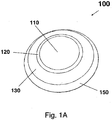
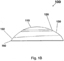
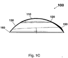
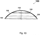
- Figs 1A-1D schematically illustrate a contact lens having an orientation/stabilization feature according to a preferred embodiment of the invention.
- the contact lens 100 has an anterior surface and an opposite posterior surface.
- the anterior surface has a mirror symmetry with respect to a vertical meridian plane and is continuous at least in first derivative.
- the anterior surface comprises a central optical zone 110, a first blending zone 120 surrounding the central optical zone 110, a peripheral zone 130 surrounding the first blending zone 120, a second blending zone 150 surrounding the peripheral zone 130, and an edge zone 160 surrounding the second blending zone 150.
- the central optical zone 110 is a circular zone which is concentric with the geometric center of the anterior surface.
- the central optical zone 110 in combination with the posterior surface provides one or more vision corrections, for example, such as astigmatism, presbyopia, prism, high-order monochromatic aberrations (e.g., a non-standard amount of spherical aberration, coma, etc.), or combinations thereof.
- the first blending zone 120 has a surface that ensures that the peripheral zone 130, the first blending zone 120 and the central optical zone 110 are tangent to each other.
- the first blending zone 120 is preferably defined by a spline-based mathematical function.
- the first blending zone 120 between the central optical zone and the peripheral zone can de-couple the optical features and the mechanical stabilization and translation features of the lens, thus preventing the introduction of prism into the optics.
- the peripheral zone 130 is designed to have a varying lens thickness which depends on positions on the anterior surface.
- the lens thickness of peripheral zone 130 remains substantially constant or increases gradually from the outer boundary of the peripheral zone to the inner boundary of the peripheral zone in a manner that the difference between two values of lens thickness at two intersection points of the upper portion of the vertical meridian with the outer and inner boundaries of the peripheral zone is preferably less than 30% ( Fig. 1C ).
- the lens thickness of the peripheral zone 130 increases gradually from the inner boundary of the peripheral zone to the outer boundary of the peripheral zone in a manner that the values of lens thickness at two intersction points of the upper portion of the vertical meridian with the outer and inner boundaries of the peripheral zone differ from each other by from about 15% to about 65% ( Fig. 1C) .
- the lens thickness of the peripheral zone 130 increases gradually along each semi-meridian from the inner boundary to the outer boundary ( Fig. 1C and Fig. 1D ).
- the lens thickness of the peripheral zone 130 remains substantially constant or increases gradually, along each semi-meridian from the outer boundary of the peripheral zone to the inner boundary of the peripheral zone in a manner that the difference between the values of lens thickness at two intersection points of any semi-meridian with the outer and inner boundaries of the peripheral zone 130 is less than 15%.
- the second blending zone 150 is designed to ensure a continuous transition from the peripheral zone 130 to the edge zone.
- the second blending zone in combination with the peripheral zone 130, weigh the lens at its lower half portion, causing it to come to an equilibrium position on the eye.
- Lens thickness maximums along semi-meridians are preferably located slightly outside (less than 0.4 mm) of the outer boundary of the peripheral zone 130 within the sector bounded by two semi-meridians preferably about 120 degree relative to the lower portion of the vertical meridian and the edge included between the two semi-meridians ( Fig. 1C and Fig. 1D ).
- the edge zone 160 is preferably circular. It is adjacent to the second blending zone and tapers with the posterior surface along the edge of the contact lens.
- the edge zone 160 in combination with the posterior surface, provides a substantially uniform thickness which may provide comfortable lens fit on an eye.
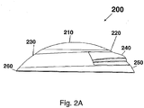
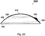
- Figs. 2A-2D schematically illustrate a translating contact lens having an orientation/stabilization feature and a translation feature according to a preferred embodiment of the invention.
- the translating contact lens 200 has an anterior surface and an opposite posterior surface.
- the anterior surface has a mirror symmetry with respect to a vertical meridian plane and is continuous at least in first derivative.
- the anterior surface comprises a central optical zone 210, a first blending zone 220 surrounding the central optical zone 110, a peripheral zone 230 surrounding the first blending zone 220, a second blending zone 250 surrounding the peripheral zone 230, and an edge zone 260 surrounding the second blending zone 250.
- the central optical zone 210 is a circular zone which is concentric with the geometric center of the anterior surface.
- the central optical zone 210 comprises a first portion to provide distant vision correction for the eye and a second portion disposed beneath the first portion to provide near vision correction for the eye.
- the first blending zone 220, the second blending zone 250 and the edge zone 260 have preferred designs as described above for a contact lens shown in Figs. 1A-1D .
- the peripheral zone 230 includes a ridge 240.
- the ridge is designed to sit on the peripheral zone 240 having a design almost identical to what described above for a contact lens shown in Figs. 1A-1D .
- the optical zone and non-optical zones (orientation/stabilization and/or translation feature) of a contact lens of the invention are designed separately.
- a contact lens of the invention can be designed using any known, suitable optical design system.
- Exemplary optical computer aided design systems for designing an optical model lens includes, but are not limited to ZEMAX (ZEMAX Development Corporation).
- ZEMAX ZEMAX Development Corporation
- the optical design will be performed using ZEMAX (ZEMAX Development Corporation).
- the design of the optical model lens can be transformed by, for example, a mechanical computer aided design (CAD) system, into a set of mechanical parameters for making a physical lens. Any know suitable mechanical CAD system can be used in the invention.
- CAD mechanical computer aided design
- the design of an optical model lens may be translated back and forth between the optical CAD and mechanical CAD systems using a translation format which allows a receiving system, either optical CAD or mechanical CAD, to construct NURBs (non-uniform rational B-splines), Bézier surfaces of an intended design or ASCII parameters that control a parametric design.
- exemplary translation formats include, but are not limited to, VDA (var der automobilindustrie) and IGES (Initial Graphics Exchange Specification). By using such translation formats, overall surface of lenses can be in a continuous form that facilitates the production of lenses having radial asymmetrical shapes.
- Bezier and NURBs surface are particular advantageous for a lens having a plurality of zones including optical zone and non-optical zones because multiple zones can be blended, analyzed and optimized.
- the mechanical CAD system is capable of representing precisely and mathematically high order surfaces.
- An example of such mechanical CAD system is Pro/Engineer from Parametric Technology.
- optical model lens refers to an ophthalmic lens that is designed in a computer system and generally does not contain other non-optical features that constitute an ophthalmic lens.
- common feature parameters of a family of ophthalmic lenses can be incorporated in the lens designing process.
- examples of such parameters include shrinkage, non-optical boundary zone and its curvature, center thickness, range of optical power, and the like.
- Any mathematical function can be used to describe the optical zone and non-optical zones of a contact lens of the invention, as long as they have sufficient dynamic range that allow the design of that lens to be optimized.
- Exemplary mathematical functions include conic, biconic and quadric functions, polynomials of any degree, Zernike polynomials, exponential functions, trigonometric functions, hyperbolic functions, rational functions, Fourier series, and wavelets.
- a spline-based mathematical function or a combination of two or more mathematical functions are used to describe the optical zone and non-optical zones of a contact lens of the invention.
- a contact lens of the invention may be produced by any convenient manufacturing means, including, for example, a computer-controllable manufacturing device, molding or the like.
- a "computer controllable manufacturing device” refers to a device that can be controlled by a computer system and that is capable of producing directly a contact lens or optical tools for producing a contact lens. Any known, suitable computer controllable manufacturing device can be used in the invention. Exemplary computer controllable manufacturing devices includes, but are not limited to, lathes, grinding and milling machines, molding equipment, and lasers.
- a computer controllable manufacturing device is a two-axis lathe with a 45° piezo cutter or a lathe apparatus disclosed by Durazo and Morgan in US patent No.
- 6,122,999 or is a numerically controlled lathe, for example, such as Optoform® ultra-precision lathes (models 30, 40, 50 and 80) having Variform® or Varimax piezo-ceramic fast tool servo attachment from Precitech, Inc.
- Optoform® ultra-precision lathes models 30, 40, 50 and 80
- Variform® or Varimax piezo-ceramic fast tool servo attachment from Precitech, Inc.
- contact lenses are molded from contact lens molds including molding surfaces that replicate the contact lens surfaces when a lens is cast in the molds.
- an optical cutting tool with a numerically controlled lathe may be used to form a metallic optical tool incorporating the features of the anterior surface of a contact lens of the invention.
- the tool is then used to make anterior surface molds that are then used, in conjunction with posterior surface molds, to form the lens of the invention using a suitable liquid lens-forming material placed between the molds followed by compression and curing of the lens-forming material.
- a contact lens of the invention or the optical tool to be used for making the same is fabricated by using a numerically controlled lathe, for example, such as Optoform® ultra-precision lathes (models 30, 40, 50 and 80) having Variform® or Varimax piezo-ceramic fast tool servo attachment from Precitech, Inc, according to a method described in international application WO 2004/011990 .
- a numerically controlled lathe for example, such as Optoform® ultra-precision lathes (models 30, 40, 50 and 80) having Variform® or Varimax piezo-ceramic fast tool servo attachment from Precitech, Inc, according to a method described in international application WO 2004/011990 .
- a translating contact lens shown in Figs. 2A-2D is created via the following process.
- a user defines a set of parameters, such as a surface tolerance, a concentricity tolerance, orientation of the lens design, the number of semi-diameter spokes to be generated for each of the anterior and posterior surfaces, creating zero point at 0,0, orientation of Z-axis, and type of lens surface (concave or convex surface) to be converted into a geometry.
- a "surface tolerance” refers to the allowed position-deviation of a projected point from an ideal position on a surface of a lens design. The deviation can be in the direction either parallel or perpendicular to the central axis of a lens design.
- a “concentricity tolerance” refers to the allowed deviation of a point from a given arc.
- a “semi-diameter spoke” refers to a curve radiating outwardly from the central axis and is perpendicular to the central axis and projected onto the surface.
- “Evenly-spaced semi-diameter spokes” means that all semi-diameter spokes radiate outwardly from the central axis and separate from each other by one equal angle.
- a “point spacing” refers to a distance between two points along the semi-diameter spoke.
- a user determines the point density to be projected onto the surface of the lens design (for example, the anterior surface) along each of the number of evenly-spaced semi-diameter spokes in a direction parallel to the central axis.
- a semi-diameter spoke at an azimuthal angle corresponds to the feature that deviates most from the base conic surface, and is selected as the semi-diameter probing spoke.
- Evenly-spaced points are projected along the semi-diameter probing spoke, in which each pairs of points are separating by a point spacing of typically 10 microns. Then all of the projected points are divided into a series of groups, with each group composed of three consecutive points, a first point, a middle point, and a third point.
- Each of the points can belong to either one group or two groups.
- One group is analyzed at a time from the central axis to the boundary, or from the boundary to the central axis, from the curvature of the surface at the middle point of the group by comparing a distance between the middle point and a line linking the first point and the third point of the corresponding group with the predetermined surface tolerance. If the distance between the middle point and the line linking the first and third points of the group is larger than the predetermined surface tolerance, the curvature of the surface at that point is sharp and an additional point is projected between the first and the middle points in that group. The point spacing between the first and additional points is equal to point spacing between the additional and middle points.
- the above-determined number of points is then projected onto the anterior surface of the lens design along each of 24, 96 or 384 semi-diameter spokes, in the preferred embodiment. Other numbers of spokes are possible.
- a semi-meridian that is continuous in first derivative is generated.
- the semi-meridian includes a series of arcs and, optionally, straight lines wherein each arc is defined by fitting at least three consecutive points into a spherical mathematical function within a desired concentricity tolerance.
- Each of the straight lines is obtained by connecting at least three consecutive points.
- the arc-fitting routine is started from the central axis to the boundary.
- conversion of the posterior surface of the lens design into geometry can be carried out according to the above-described procedure.
- a mini-file, or equivalent format containing both the information for the header and the information about the geometry of the lens is generated.
- This mini-file also contains a zero semi-meridian that is based on the average height of each of the other meridians at each of radial locations and that gives the Variform or Varimax a zero position on which it can base its oscillation calculations.
- all semi-meridians have the same number of zones. This is accomplished by copying the last zone of a semi-meridian for a number of times to equalize the numbers of zones for all meridians.
- the mini-file is completed, it is loaded into an Optoform® ultra-precision lathe (models 30, 40, 50 or 80) having Variform® piezo-ceramic fast tool servo attachment and run to produce a translating contact lens.
- a contact lens of the invention can be characterized by any known suitable optical metrology system.
- the vertically oriented coma-like and other wavefront aberrations of the lens can be determined by any suitable methods known to one skilled in the art, including without limitation, Shack-Hartmann techniques, Tscherning techniques, retinal ray tracing techniques, and spatially-resolved refractometer techniques.
- the present invention also provides a method of manufacturing an ophthalmic lens of the invention.
- the invention in another aspect, provides a method for producing a contact lens having an orientation/stabilization feature of the invention as described above.
- the method comprises the steps of designing the anterior surface and the posterior surface of the contact lens, wherein anterior surface includes: a vertical meridian, a horizontal meridian, a central optical zone, a peripheral zone, an edge zone, a first blending zone extending outwardly from the central optical zone to the peripheral zone and providing a continuous transition from the central optical zone to the peripheral zone, a second blending zone extending outwardly from the peripheral zone to the edge zone and providing a continuous transition from the peripheral zone to the edge zone.
- the anterior surface has a mirror symmetry with respect to a vertical meridian plane and is continuous at least in first derivative.
- the contact lens is weighed at its lower half portion by varying lens thickness within the peripheral zone and second blending zone to cause it to come to an equilibrium position on the eye and has a lens thickness profile characterized by that the lens thickness, in a sector bounded by two sector-bounding semi-meridians at about 35 degrees or larger relative to the lower portion of the vertical meridian and by a portion of the edge included between the two sector-bounding semi-meridians, increases gradually from the inner boundary of the peripheral zone along each semi-meridian until reaching a lens thickness maximum and then decreases.
- the central optical zone is designed independently from the peripheral zone and then blended with the peripheral zone by using the first blending zone.
- the lens thickness profile is further charaterized by that: (1) the lens thickness, along the upper portion of the vertical meridian, of the contact lens in the peripheral zone remains substantially constant or increases gradually from the outer boundary of the peripheral zone to the inner boundary of the peripheral zone in a manner that the difference between the values of lens thickness at two intersection points of the upper portion of the vertical meridian with the outer and inner boundaries of the peripheral zone is less than 50%, preferably by less than 30%, more preferably less than 15%; and/or (2) the lens thickness, along the lower portion of the vertical meridian, of the contact lens in the peripheral zone increases gradually from the inner boundary of the peripheral zone to the outer boundary of the peripheral zone in a manner that the difference between the values of lens thickness at two intersection points of the lower portion of the vertical meridian with the inner and outer boundaries of the peripheral zone is from about 15% to about 65%.
- the manufacturing method of the invention preferably further comprises a step of producing an ophthalmic lens by a manufacturing means as described above.
- each contact lens in the series comprises an anterior surface and a posterior surface, wherein the posterior surface of each lens in the series is substantially identical to each other, wherein the anterior surface of each lens in the series include: a vertical meridian, a horizontal meridian, a central optical zone, a peripheral zone, an edge zone, a first blending zone extending outwardly from the central optical zone to the peripheral zone and providing a continuous transition from the central optical zone to the peripheral zone, a second blending zone extending outwardly from the peripheral zone to the edge zone and providing a continuous transition from the peripheral zone to the edge zone, wherein the peripheral zone, the second blending zone and the edge zone of each lens in the series is identical to each other whereas the central optical zone and the first blending zone of each lens in the series are different from each other.
- each lens has a mirror symmetry with respect to a vertical meridian plane and is continuous at least in first derivative.
- Each lens is weighed at its lower half portion by varying lens thickness within the peripheral zone and second blending zone to cause it to come to an equilibrium position on the eye and has a lens thickness profile characterized by that lens thickness, in a sector bounded by two sector-bounding semi-meridians at about 35 degrees or larger relative to the lower portion of the vertical meridian and by a portion of the edge included between the two sector-bounding semi-meridians, increases gradually from the inner boundary of the peripheral zone along each semi-meridian until reaching a lens thickness maximum and then decreases.
- the lens thickness profile is further charaterized by that: (1) the lens thickness, along the upper portion of the vertical meridian, of the contact lens in the peripheral zone remains substantially constant or increases gradually from the outer boundary of the peripheral zone to the inner boundary of the peripheral zone in a manner that the difference between the values of lens thickness at two intersection points of the upper portion of the vertical meridian with the outer and inner boundaries of the peripheral zone is less than 50%, preferably by less than 30%, more preferably less than 15%; and/or (2) the lens thickness, along the lower portion of the vertical meridian, of the contact lens in the peripheral zone increases gradually from the inner boundary of the peripheral zone to the outer boundary of the peripheral zone in a manner that the difference between the values of lens thickness at two intersection points of the lower portion of the vertical meridian with the inner and outer boundaries of the peripheral zone is from about 15% to about 65%.
- the invention in another further aspect, provides a method for producing a series of contact lenses which each correct different vision difficiencies.
- the method comprises the steps of: designing the anterior surface and the posterior surface of the contact lens, wherein the posterior surface of each lens in the series is substantially identical to each other, wherein the anterior surface of each lens in the series include: a vertical meridian, a horizontal meridian, a central optical zone, a peripheral zone, an edge zone, a first blending zone extending outwardly from the central optical zone to the peripheral zone and providing a continuous transition from the central optical zone to the peripheral zone, a second blending zone extending outwardly from the peripheral zone to the edge zone and providing a continuous transition from the peripheral zone to the edge zone, wherein the peripheral zone, the second blending zone and the edge zone of each lens in the series is identical to each other whereas the central optical zone and the first blending zone of each lens in the series are different from each other.
- each lens has a mirror symmetry with respect to a vertical meridian plane and is continuous at least in first derivative.
- Each lens is weighed at its lower half portion by varying lens thickness within the peripheral zone and second blending zone to cause it to come to an equilibrium position on the eye and has a lens thickness profile characterized by that lens thickness, in a sector bounded by two sector-bounding semi-meridians at about 35 degrees or larger relative to the lower portion of the vertical meridian and by a portion of the edge included between the two sector-bounding semi-meridians, increases gradually from the inner boundary of the peripheral zone along each semi-meridian until reaching a lens thickness maximum and then decreases.
- the central optical zone is designed independently from the peripheral zone and then blended with the peripheral zone by using the first blending zone.
- the lens thickness profile is further charaterized by that: (1) the lens thickness, along the upper portion of the vertical meridian, of the contact lens in the peripheral zone remains substantially constant or increases gradually from the outer boundary of the peripheral zone to the inner boundary of the peripheral zone in a manner that the difference between the values of lens thickness at two intersection points of the upper portion of the vertical meridian with the outer and inner boundaries of the peripheral zone is less than 50%, preferably by less than 30%, more preferably less than 15%; and/or (2) the lens thickness, along the lower portion of the vertical meridian, of the contact lens in the peripheral zone increases gradually from the inner boundary of the peripheral zone to the outer boundary of the peripheral zone in a manner that the difference between the values of lens thickness at two intersection points of the lower portion of the vertical meridian with the inner and outer boundaries of the peripheral zone is from about 15% to about 65%.
Landscapes
- Health & Medical Sciences (AREA)
- Ophthalmology & Optometry (AREA)
- Physics & Mathematics (AREA)
- General Health & Medical Sciences (AREA)
- General Physics & Mathematics (AREA)
- Optics & Photonics (AREA)
- Eyeglasses (AREA)
- Lenses (AREA)
Description
- This invention is related to contact lenses. In particular, the present invention is related to contact lenses, which require a rotational and/or orientation stability on an eye, such as toric contact lenses, biofocal or multifocal contact lenses, toric multifocal contact lenses, contact lenses capable of correcting high-order wavefront aberrations and the like.
- Contact lenses are widely used for correcting many different types of vision deficiencies. These include defects such as near-sightedness and far-sightedness (myopia and hypermetropia, respectively), astigmatism, and defects in near range vision usually associated with aging (presbyopia).
- Astigmatism occurs as the refractive error in an eye is dependent upon meridian. This is usually due to one or more refractive surfaces, most commonly the anterior cornea, having a toroidal shape. It may also be due to one or more surfaces being transversely displaced or tilted. Astigmatism is usually regular, which means that the principal (maximum and minimum power) meridians are perpendicular to each other. People with astigmatism have blurred vision at all distances, although this may be worse at distance or near, depending on the type of astigmatism. These people may complain of sore eyes and headaches associated with demanding visual tasks. Astigmatism can corrected with an astigmatic ophthalmic lens, which usually has one spherical surface and one toroidal (cylindrical) surface.
- It is believed that presbyopia occurs as a person ages when the lens of eye loses its elasticity, eventually resulting in the eye losing the ability to focus at near distances (when distance vision is corrected), such as the normal reading distance, and in some cases at intermediate distances. Presbyopic persons (presbyopes) complain of difficulty performing close tasks. To compensate for presbyopia, ophthalmic lenses are required to be more positively powered or less negatively powered than the distance correction. Some presbyopic persons have both near vision and distance vision defects, requiring simultaneous or alternating vision lenses to properly correct their vision.
- Simultaneous vision lenses refers to the class of bifocal or multifocal contact lenses in which optical power for distance vision and near vision are positioned simultaneously within the pupil area of a user's eye. They are generally composed of, within the pupil area of the eye, two or more concentric annular zones which alternately provide the distance and near power, or a multifocal zone having an aspheric surface which provides a continuous gradient of optical power over a selected range of powers. The visual performance of the simultaneous vision lens design is limited by its dependence on pupil size. Moreover, with all simultaneous vision lenses a partially degraded image of an object is projected onto the retina. The consequence of this image degradation is a reduction in visual actuity and/or contrast sensitivity (less signal, more noise), and the quality of the degraded image may or may not be acceptable to the patient. The clinical effects of this degradation may be measured objectively in terms of reduced visual acuity and contrast sensitivity. The subjective effects of the degradation are perceived by the patient in various ways which are collectively referred to as subjective blur. Therefore, when wearing a simultaneous vision lens, the patient may not be selecting between separate distance and near images. Rather, in the presence of subjective blur the patient may be attempting to function with the reduced level of spatial information content that is provided by a degraded image.
- Alternating vision refers to the class of segmented (or translating) bifocal contact lenses in which the lens is divided into two optical zones. Typically the superior (or upper) zone is for distance vision correction, whereas the lower zone is for near vision correction. The distance portion (upper zone) subtends the pupil of the eye in primary gaze, while in downward gaze, the add power or near portion (lower zone) of the lens subtends the pupil. Effective use of an alternating vision lens requires vertical translation of the optical zones across the pupil when the eye changes from primary gaze to a downward gaze. In such a situation, the lens must move such that the pupil is predominately subtended by the distance zone for primary gaze and predominately subtended by the near zone for down-gaze. Unlike the simultaneous vision lenses, the visual performance of the alternating vision lenses is not significantly limited by its dependence on pupil size.
- Moreover, large population of presbyopes also has an astigmatism vision error. Those presbyopes may require to wear contact lenses capable of correcting both astigmatism and presbyopia. Such contact lenses are disclosed in US patent application Publ. No.
2004-0021824 filed July 31, 2002 , and have a cylindrical optical surface (or power) to correct astigmatism vision errors and a multifocal power to compensate for presbyopia. - Human eyes may suffer not only low-order monochromatic aberrations, such as defocus, astigmatism and prism, but also high-order monochromatic aberrations, such as a non-standard amount of spherical aberration, coma, and other irregular high-order aberrations. High order aberrations present in an eye can blur images formed on the retina, which can impair vision. The impact of these higher-order aberrations on retinal image quality can become significant in some cases, for example, in older eyes, in normal eyes with large pupils, and in the eyes of many people with irregular astigmatism, keratoconus, corneal dystrophies, post penetrating keratoplasty, scarring from ulcerative keratitis, corneal trauma with and without surgical repair, and sub-optimal outcome following refractive surgery. For those people, visual acuity of 20/20 or better can be achieved with customized contact lenses or contact lenses capable of correcting high-order monochromatic aberrations of the human eye. Unlike current contact lenses, customized contact lenses or contact lenses capable of correcting high order aberrations inevitably need to have a complex surface design without restrictions of rotational symmetry.
- Effective use of each of the above described contact lenses and the like requires a rotational and/or orientational stability on an eye. One of the most commonly utilized basic techniques, which can maintain a predetermined orientation of a contact lens on an eye, is prism stabilization. By using this technique, a contact lens is provided with prism ballast, which is generally a base-down prism to increases the mass of the lower portion of the lens and to create a weighting effect to orient the lens. However, there are some disadvantages associated with designs of contact lenses having prism ballast in the prior art. Those lenses are not comfortable to wear and/or not highly effective in maintaining lens orientation. Furthermore, contact lenses with prism ballast as orientation feature may not be able to provide better visual performance since they tend to have optical distortions known as prism.
- There are other orientation/stabilization features which have been used or proposed to be used in contact lenses. Exemplary orientation/stabilization features include a faceted surface in which parts of the lens geometry is removed to control the lens orientation and double slab-off features which have a top slab-off zone and a bottom slab-off zone zones to maintain the lens orientation on the eye as well as a visual cue on the lenses so that a wearer can insert the lenses in the proper orientation. The lenses with these orientation/stabilization features are not comfortable to wear and/or not highly effective in maintaining lens orientation.
- A contact lens having a uniform horizontal thickness profile is disclosed in
US6467903 . Therefore, there is a need for a contact lens with an orientation feature, wherein the lens is substantially free of prism optical effects and is comfortable to wear. - An object of the invention is to provide a contact lens having an orientation feature which can maintain effectively the lens in a desired rotational and orientation on an eye, wherein the lens is substantially free of prism optical effects and is comfortable to wear.
- Another object of the invention is to provide a method for producing a contact lens having an orientation feature which can maintain a predetermined orientation on an eye, wherein the lens is substantially free of prism optical effects and is comfortable to wear.
- In accomplishing the foregoing, there is provided, in accordance with one aspect of the present invention, a contact lens according to claim 1, a series of contact lenses according to claim 4 and a method of producing a contact lens according to claim 7. In preferred embodiments, the lens thickness profile is further charaterized by that: (1) the lens thickness, along the upper portion of the vertical meridian, of the contact lens in the peripheral zone remains substantially constant or increases gradually from the outer boundary of the peripheral zone to the inner boundary of the peripheral zone in a manner that the difference between the values of lens thickness at two intersection points of the upper portion of the vertical meridian with the outer and inner boundaries of the peripheral zone is less than 50%, preferably by less than 30%, more preferably less than 15%;
- These and other aspects of the invention will become apparent from the following description of the preferred embodiments taken in conjunction with the following drawings. As would be obvious to one skilled in the art, many variations and modifications of the invention may be effected without departing from the scope of the novel concepts of the disclosure.
-
-
Fig. 1A is an oblique view of a contact lens according to a preferred embodiment of the invention. -
Fig. 1B is a side view of a contact lens shown inFig. 1A . -
Fig. 1C is a vertical cross-section view of the contact lens shown inFig. 1A . -
Fig. 1D is a horizontal cross-section view of the contact lens shown inFig. 1A . -
Fig. 2A is side view of a contact lens according to a preferred embodiment of the invention. -
Fig. 2B is a vertical cross-section view of the contact lens shown inFig. 2A . -
Fig. 2C is a horizontal cross-section view of the contact lens shown inFig. 2A . -
Fig. 2D is a diagonal cross-section view of the contact lens shown inFig. 2A . - Reference now will be made in detail to the embodiments of the invention. It will be apparent to those skilled in the art that various modifications and variations can be made in the present invention without departing from the scope or spirit of the invention. For instance, features illustrated or described as part of one embodiment, can be used on another embodiment to yield a still further embodiment. Thus, it is intended that the present invention cover such modifications and variations as come within the scope of the appended claims and their equivalents. Other objects, features and aspects of the present invention are disclosed in or are obvious from the following detailed description. It is to be understood by one of ordinary skill in the art that the present discussion is a description of exemplary embodiments only, and is not intended as limiting the broader aspects of the present invention.
- Unless defined otherwise, all technical and scientific terms used herein have the same meaning as commonly understood by one of ordinary skill in the art to which this invention belongs. Generally, the nomenclature used herein and the laboratory procedures are well known and commonly employed in the art. Conventional methods are used for these procedures, such as those provided in the art and various general references. Where a term is provided in the singular, the inventors also contemplate the plural of that term. The nomenclature used herein and the laboratory procedures described below are those well known and commonly employed in the art.
- The present invention is generally related to contact lenses which require a rotational and/or orientation stability on an eye. In particular, the present invention is related to contact lenses having an orientation/stabilization feature which can maintain a predetermined orientation on an eye, wherein the lens is substantially free of prism optical effects and is comfortable to wear.
- In one aspect, the present invention provides a contact lens according to claim 1. A "vertical meridian", in reference to the anterior surface of a contact lens, refers to an imaginary line running vertically from the top, through the geometric center, to the bottom on the anterior surface, when said lens is maintained at a predetermined orientation on an eye. A "horizontal meridian", in reference to the anterior surface of a contact lens, refers to an imaginary line running horizontally from the left side, through the center, to the right side on the anterior surface, when said lens is maintained at a predetermined orientation on an eye. The horizontal and vertical meridians are perpendicular to each other.
- A "outer boundary", in reference to a zone other than a central optical zone on the anterior surface of a contact lens, refers to one of two peripheral boundaries of that zone which is further away from the geometric center of the anterior surface.
- An "inner boundary", in reference to a zone other than a central optical zone on the anterior surface of a contact lens, refers to one of two peripheral boundaries of that zone which is closer to the geometric center of the anterior surface.
- A "semi-meridian" refers to an imaginary line running radially from the geometric center of the anterior surface of a contact lens to the edge of the contact lens.
- The "upper portion of the vertical meridian" refers to one half vertical meridian that is above the geometric center of the anterior surface of a contact lens, when said lens is maintained at a predetermined orientation on an eye.
- The "lower portion of the vertical meridian" refers to one half vertical meridian that is below the geometric center of the anterior surface of a contact lens, when said lens is maintained at a predetermined orientation on an eye.
- A "continuous transition", in reference to two or more zones, means that these zones are continuous at least in first derivative, preferably in second derivative.
- A "vertical meridian plane" refers to a plane that cuts through the optical axis of a contact lens and a vertical meridian on the anterior surface of the contact lens.
- A "sector", in reference to the anterior surface of a contact lens, means an area bounded by two sector-bounding semi-meridians at an equal angle relative to the lower portion of the vertical meridian and by a portion of the edge included between the two sector-bounding semi-meridians. The edge included between the two sector-bounding semi-meridians is the sum of a first portion of the edge between one of the two semi-meridians and the lower porion of the vertical meridian and a second portion of the edge between the other semi-meridian and the lower porion of the vertical meridian.
- Two "sector-bounding semi-meridians" refer to two semi-meridians which divides the anterior surface into two sectors.
- "Lens thickness" refers to a shortest distance from a point on the anterior surface to the posterior surface of a contact lens.
- A "percentage of difference between two values of lens thickness" is obtained by first subtracting the smaller value from the larger value and then dividing the subtracting result with the larger value and finally multiplying it with 100.
- The central optical zone of a contact lens can have any shape suitable for a contact lens design, for example, such as circular, oval, or the like. Preferably, the central optical zone is circular. More preferably, the central optical zone is a circular zone which is concentric with the geometric center of the anterior surface, though the center of the central optical zone can deviate from the geometric center of the anterior or posterior surface by up to 2 mm. Where the central optical zone is concentric with the geometric center of the anterior or posterior surface, the vertical and horizontal meridians each pass through the center of the central optical zone. Where the center of the central optical zone deviates from the geometric center of the anterior or posterior surface, the center of the optical zone is on the vertical meridian and less than about 1.0 mm from the geometric center of the anterior surface.
- A "blending zone" refers to a non-optical zone located between two zones and providing a continuous transition between these two zones.
- The presence of a first blending zone can allow to separately and independently design the central optical zone and the peripheral zone, so as to ensure a continuous transition from the central optical zone to the peripheral zone. With a first blending zone between the central optical zone and the peripheral zone, a contact lens can be produced to have flexion points and/or sharp boundaries at the junction between two zones being eliminated and thereby provide improved wearer's comfort. In addition, the first blending zone between the central optical zone and the peripheral zone can de-couple the optical features and the mechanical stabilization and translation features of the lens, thus preventing the introduction of prism into the optics. The first blending zone has a surface that ensures that the peripheral zone, the first blending zone and the central optical zone are tangent to each other. The blending zone of the invention can be any surface described by a mathematical function, preferably a spline-based mathematical function, or made of different tangent surface patches.
- "Tangent surface patches" refer to combinations of surfaces with curvatures that are continuous in first derivative, preferably in second derivative, from each other.
- The peripheral zone can be composed of one or more peripheral bands or regions which are patched together to form a continuous surface. It is discovered that, when a contact lens has in the peripheral zone and the second blending zone a lens thickness profile as described above, such contact lens can be maintained effectively at a predetermined orientation on an eye. Like a conventional lens ballast, the orientation feature of the invention works by weighing the lens at its lower half portion, causing it to come to an equilibrium position on the eye. With such orientation feature, the optical zone of the anterior surface can be designed independently to provide an optimal visual performance.
- In another preferred embodiment, lens thickness has a value ranging between about 110 to about 150 micrometers in the central 90% of the peripheral zone along the upper portion of the vertical meridian. Actual values will depend on material properties and base curve (posterior surface) parameters.
- In another preferred embodiment, lens thickness at the intersection point of the lower portion of the vertical meridian with the inner boundary of the central 90% of the peripheral zone is from about 200 micrometers to about 280 micrometers; lens thickness at the intersection point of the lower portion of the vertical meridian with the outer boundary of the central 90% of the peripheral zone is from about 320 micrometers to about 400 micrometers. Actual values will depend on material properties and base curve (posterior surface) parameters. The size of the sector can be varied. The sector is bound by two sector-bounding semi-meridians preferably at about 90 degrees, more preferably at about 120 degree, even more preferably about 135 degree, relative to the lower portion of the vertical meridian and the edge included between the two sector-bounding semi-meridians. In those preferred embodiments, lens thickness maximums along the horizontal meridian are preferably from about 200 micrometers to about 300 micrometer. Where the sector is bound by two sector-bounding semi-meridians preferably at about 120 degree relative to the lower portion of the vertical meridian and the edge included between the two sector-bounding semi-meridians, lens thickness, in this sector, increases gradually along each semi-meridian until reaching a lens thickness maximum and then decreases whereas in the other remaining sector lens thickness remains substantially constant or increases gradually, along each semi-meridian within this remaining sector, from the outer boundary of the peripheral zone to the inner boundary of the peripheral zone in a manner that the difference between the values of lens thickness at two intersection points of any semi-meridian with the outer and inner boundaries of the peripheral zone is less than 15%.
- In another preferred embodiment, lens thickness maximums along semi-meridians are located slightly inside of, along or slightly outside of the outer boundary of the peripheral zone within the sector. More preferably, lens thickness maximums along semi-meridians are located slightly outside (less than 0.4 mm) of the outer boundary the peripheral zone within the sector.
- In another preferred embodiment, distances between the edge of the lens and any points along the outer boundary of the peripheral zone within the sector are from about 0.6 mm to about 2.0 mm.
- In another preferred embodiment, the entire peripheral zone of a contact lens of the invention has a continuity in first derivative and/or in second derivative. Such peripheral zone can be a continuous surface defined by one or more mathematical functions, preferably by a spline-based mathematical function, or is made of several different surface patches.
- Where a contact lens is a translating multifocal lens or the like that requires vertical translation of the optical zones across the pupil when the eye changes from primary gaze to a downward gaze, it is preferably that the peripheral zone comprises a ridge feature disposed below the central optical zone and extending outwardly from the peripheral zone (the anterior surface) to enable engagement with a lower eyelid of a user and thereby provide vertical translation support for the contact lens when being worn by the user. More preferably, the peripheral zone comprises a ramped ridge zone as disclosed in US patent application Publ. No.
2004-0017542, filed on July 24, 2002 , entitled "Translating Contact Lens Having A Ramped Ridge". The ramped ridge zone is disposed below the optical zone and includes a upper boundary, a lower ramped boundary, a latitudinal ridge that extends outwardly from the anterior surface, and a ramp that extends dowardly from the lower ramped boundary and has a curvature or slope that provides a varying degree of interaction between the ramped ridge zone and the lower eyelid depending on where the lower eyelid strikes the ramped ridge zone. The lower eyelid of the eye is engaged with at least some portion of the ramped ridge zone at all times. Such ramped ridge zone can provide wearer's comfort and also is capable of controlling contact lens position on an eye in primary gaze and/or translating amount across the eye when the eye changes from gazing at an object at a distance to gazing at an object at an intermediate distance or at a nearby object. - One advantage of incorporating a ramp in the ramped ridge zone is that it can provide a smooth transition zone for the eyelid to "ramp up" the ridge. This gradual engagement will benefit the wearer by increasing comfort and reducing lens sensation in the eye because the ridge will always be engaged.
- Another advantage of incorporating a ramp in the ramped ridge zone is that, since the ramp slope can determine lens position on an eye in primary gaze (horizontal), a lens design for a desired visual performance can be reliably implemented in the production of translating contact lenses. For example, a ramp is composed of a simple spherical curvature. The slope of a ramp depends on the radius of the curvature. Where a curvature has a large radius, the ramp is longer and steep. Where a curvature has a small radius, the ramp is shorter and flat. For a bifocal translating contact lens, the curvature of a ramp can have a radius of between 0.1 to 2.0 mm to provide a desired lens position on the eye in the primary gaze.
- As will be readily appreciated by those of skill in the art, many different types of ramped ridge zones are possible with the present invention. Exemplary preferred ramped ridge zones include without limitation to: a ramped ridge zone having a flattened lower ramp edge and a flattened latitudinal ridge; and a ramped ridge zone having two bumps formed at the two end of the latitudinal ridge the elevation height of which are higher at the both ends than in the middle. The above ramped ridge zones may accommodate better to the lower eyelid of the eye, and may distribute more uniformly translating stress over the entire lens-interacting portion of the lower eyelid.
- In a preferred embodiment, the entire peripheral zone including ridge features or ramped ridge features of a contact lens of the invention has a continuity in first derivative and/or in second derivative. Such peripheral zone can be a continuous surface defined by one or more mathematical functions, preferably by a spline-based mathematical function, or is made of several different surface patches.
- The maximum lens thickness of a ridge or ramped ridge is preferably from about 400 micrometers to about 600 micrometers. Actual values will depend on material properties and base curve (posterior surface) parameters.
- The second blending zone is designed to ensure a continuous transition from the peripheral zone to the edge zone and to weigh, in combination with the peripheral zone, the lens at its lower half portion, causing it to come to an equilibrium position on the eye. With a second blending zone between the peripheral zone and the edge zone, a contact lens can be produced to have flexion points and/or sharp boundaries at the junction between two zones being eliminated and thereby provide improved wearer's comfort. The second blending zone can be any surface described by a mathematical function, preferably a spline-based mathematical function, or made of different tangent surface patches.
- The anterior surface of a contact lens comprises an edge zone which is adjacent to the second blending zone. The edge zone, in combination with the posterior surface, provides a substantially uniform thickness which may provide comfortable lens fit on an eye. Preferably, the edge zone is circular.
- Contact lenses of the invention can be either hard or soft lenses. Soft contact lenses of the invention are preferably made from a soft contact lens material, such as a silicon or fluorine-containing hydro-gel or HEMA. It will be understood that any lens material can be used in the production of a contact lens of the invention.
- A contact lens of the invention can be a toric, multifocal, toric multifocal contact lens, customized contact lenses, or the like.
- A "customized contact lens", as used herein, means: (1) a contact lens that is designed using input of wavefront aberration measurements of an eye of an individual and be able to correct higher-order wavefront aberrations; and/or (2) a contact lens that has a posterior surface accommodating the corneal topography of an eye of an individual or a corneal topography statistically represent a segment of population.
- The wavefront aberrations of an eye of an individual can be determined by any suitable methods known to one skilled in the art, including without limitation, Shack-Hartmann techniques, Tscherning techniques, retinal raytracing techniques, and spatially-resolved refractometer techniques. For example, Liang et al. in J. Optical Soc. Am. 11:1-9, teach how to determine wavefront aberrations of an eye at various pupil diameters using a Hartmann-Shack system. The wavefront aberrations generally are quantified in Zernike polynomials which are a set of functions that are orthogonal over the unit circle. Since Zernike polynomials are orthogonal, the aberrations are separable and can be treated as such. The first order Zernike modes are the linear terms. The second order Zernike modes are the quadratic terms, which correspond to the aberrations such as defocus and astigmatism. The third order Zernike modes are the cubic terms, which correspond to the coma and coma-like aberrations. The fourth order Zernike modes contain spherical aberrations as well as other modes. The fifth Zernike modes are the higher-order, irregular aberrations. Local irregularities in the wavefront within the pupil are represented by these higher-order Zernike modes.
- "High-order" aberrations of an eye as used herein refers to monochromatic aberrations beyond defocus and astigmatism, namely, third order, fourth order, fifth order, and higher order wavefront aberrations.
- A contact lens, which has a posterior surface capable of accommodating the corneal topography of an eye or a corneal topography statistically represent a segment of population, will provide a good or adequate fit to the cornea of that eye and therefore enhance the wearer's comfort. It is believed that the posterior surface of a contact lens does not need to match perfectly the corneal topography of an eye. A perfect match means the posterior surface of a contact lens is exactly superimposable on a corneal topography. A contact lens, which has a posterior surface perfectly matching the corneal topography of an eye, may have inadequate on-eye movement of the lens and may have an adverse impact on wearer's comfort.
- Corneal topographic data can be acquired using a corneal topographer or videokeratoscope. Corneal topography data may be in any forms suitable for use in designing an ophthalmic lens. Exemplary forms include, but are not limited to, Zernike polynomials, point cloud data and the like. Preferably, corneal topography data is in a form in which the wavefront aberrations of an eye are quantified.
- Based on aberration measurements of an eye of an individual, the central optical zone on the anterior surface of a customized contact lens is designed in various ways not only to correct low order aberrations (defocus, astigmatism, and prism) but also to correct one or more high order aberrations.
- A customized contact lens of the invention can be designed and produced preferably by using methods described in
PCT patent application No. WO 02/088830 - As will be readily appreciated by those of skill in the art, many different types of optical zones on either or both of the anterior surface and posterior surface are possible with the present invention. Preferably, these different types of optical zones are on the anterior surface.
- In a preferred embodiment, at least one of the optical zones of the anterior and posterior surfaces of a contact lens of the invention includes a first portion to provide distance vision correction for the eye and a second portion disposed beneath the first portion to provide near vision correction for the eye. In particular, the anterior surface of a contact lens includes a central optical zone having at least a first optical zone for primary gaze, a second optical zone for down-gaze and an optical blending zone between the first and second optical zones, wherein the optical blending zone has a surface that ensures a smooth surface transition from the first optical zone to the second optical zone and that allows the first and second optical zone to be designed independently and optimally so that ghost images or blur from the transition between the first and second optical zones can be minimized or eliminated. Such a preferred lens is disclosed in a copending
U.S. patent application No. 60/446,658 filed February 11, 2003 - The first optical zone is located in the upper portion of the central optical zone. "The first optical zone being located in the upper portion of the central optical zone" means that at least 60%, preferably, preferably at least 80%, more preferably at least 90%, of the first optical zone is located in the half central optical zone above the horizontal meridian. It is understood that the distance vision zone can be larger than or smaller than or equal to the half central optical zone above the horizontal meridian.
- Preferably, the lower boundary line with the optical blending zone of the first optical zone is at or below a horizontal line passing through the center of the central optical zone (the horizontal meridian or line parallel with the horizontal meridian) at least in its central portion (i.e., around the intersection point of the lower boundary line with the vertical meridian or with a line parallel to the vertical meridian and passing through the center of the central optical zone). More preferably, the lower boundary line with the optical blending zone of the first optical zone is below a horizontal line passing through the center of the central optical zone.
- The apex of first optical zone 12 preferably coincides with the center of the central optical zone. The optical axis of the lens passes through the apex of the first optical zone and the center of the optical zone of the posterior surface (base curve). The first optical zone can be defined by any mathematical function, for example, a spherical function, a conic function, a biconic function, Zernike polynomials, a spline-based mathematical function or combinations thereof.
- The second optical zone typically is a near distance optical zone for down-gaze (for reading). The second optical zone is located below the optical blending zone 16. The vertex center of the second optical zone is preferably located at the intersection of the vertical meridian with the boundary line of the second optical zone with the optical blending zone. The intersection point is preferably on the order of 1 mm, below the apex (center point) of the first optical zone, though other separation distances are possible. The second optical zone can be defined by any mathematical function, for example, a spherical function, a conic function, a biconic function, Zernike polynomials, a spline-based mathematical function or combinations thereof.
- For a segmented bifocal contact lens, the images from both the first and second optical zones on eye, must be laterally coincident to minimize or eliminate ghost images. Ghost images are caused when the images from multiple optical zones on eye have lateral separation. The images from both zones will have an axial separation, on eye, typical of a bifocal lens. As embodied herein, the line passing through the vertex center of the second optical zone and the center of curvature at the vertex center of the second optical zone preferably intersects the line passing through the apex of the first optical zone and the center of curvature at the apex of the posterior surface, wherein the intersection point is within 2 mm of the center of curvature at the apex of the base optical surface. Such optical zone may properly align the lateral images near the optical axis of the lens and controls image jump to the wearer.
- In a more preferred embodiment, the optimal alignment of the second optical zone is controlled by rotating the second optical zone around the apex of the second optical zone. To properly align the lateral images, the line passing through the vertex center of the second optical zone and the center of curvature at the vertex center of the second optical zone should pass through the center of curvature of the (posterior) base curve surface. However, in the preferred embodiment, the asymmetrical stabilization and translation features of the lens require that the line passing through the vertex center of the second optical zone and the center of curvature at the vertex center of the second optical zone intersects the central axis of the posterior (or base curve) surface slightly displaced of the center of curvature.
- In another preferred embodiment, at least one of the optical zones of the anterior and posterior surfaces of a contact lens of the invention has a toric optics feature to correct for a wearer's astigmatism.
- In another preferred embodiment, one of the optical zones of the anterior and posterior surfaces of a contact lens of the invention comprises a toric optics feature and the other optical zone comprises a multifocal optics feature, wherein both the optical zones combine together to provide a cylindrical optical power to correct astigmatism vision errors and a multifocal power to compensate for presbyopia. The multifocal optics feature can be multiple concentric annular zones or a progressive power zone or the like. Preferably, the multifocal optics feature is a progressive power zone which is substantially concentric with the central axis. The progressive power zone has a diameter of preferably about 1.0 mm to about 3.0 mm, more preferably about 1.5 mm to 2.2 mm. The toric optics feature can be on the anterior surface and the multifocal optics feature can be on the posterior surface or vice versa. Preferably, the toric optics feature is on the anterior surface and the multifocal optics feature is on the posterior surface. The toric optics feature can have the shape of the toric optics of any conventional toric lens. Preferably, the toric optics feature is circular. More preferably, circular toric optics feature is substantially concentric with the central axis.
- In another preferred embodiment, one of the optical zones of the anterior and posterior surfaces of a contact lens of the invention comprises a toric optics feature and a multifocal optics feature therewithin, wherein the two optical zones combine together to provide a cylindrical optical power to correct astigmatism vision errors and a multifocal power to compensate for presbyopia. Both the toric and multifocal optics features can be either on the anterior surface or on the posterior surface. Preferably, both the toric and multifocal optics features are on the anterior surface.
- In another preferred embodiment, at least one of the optical zones of the anterior and posterior surfaces of a contact lens of the invention provides a vertically oriented coma-like wavefront aberration. Such lens is capable of correcting presbyopia or of preventing children's eyes from becoming severely myopic and is described in a copending patent application No.
60/443,400 filed January 29, 2003 - A "coma-like wavefront aberration" refers to a wavefront aberration which is, or is an equivalent of, a wavefront aberration described by any one of third order, fifth order, seventh order Zernike coma-like terms, and combinations thereof in the proposed OSA Standard (Optical Society of America) Zernike Polynomials.
- A table of the proposed OSA Standard (Optical Society of America) Zernike Polynomials up to 7th order is displayed below (More information on Zernike polynomials is available on http://color.eri.harvard.edu/standardization/standards TOPS4.pdf).
Table of Zernike Polynomials in Polar Coordinates up to 7th order (36 terms) j n m 
j n m 
0 0 0 1 18 5 1 
1 1 -1 2 ρ sin θ 19 5 3 
2 1 1 2 ρ cos θ 20 5 5 
3 2 -2 
21 6 -6 
4 2 0 
22 6 -4 
5 2 2 
23 6 -2 
6 3 -3 
24 6 0 
7 3 -1 
25 6 2 
8 3 1 
26 6 4 
9 3 3 
27 6 6 
10 4 -4 
28 7 -7 4 ρ7 sin 7θ 11 4 -2 
29 7 -5 4 (7ρ7-6ρ5) sin 5θ 12 4 0 
30 7 -3 4 (21ρ7-30ρ5+10ρ3) sin 3θ 13 4 2 
31 7 -1 4 (35ρ7-60ρ5+30ρ3-4ρ) sin θ 14 4 4 
32 7 1 4 (35ρ7-60ρ5+30ρ3-4ρ) cos θ 15 5 -5 
33 7 3 4 (21ρ7-30ρ5+10ρ3) cos 3θ 16 5 -3 
34 7 5 4 (7ρ7-6ρ5) cos 5θ 17 5 -1 
35 7 7 4 ρ7 cos 7θ - A vertically oriented coma-like aberration is wavefront aberration which is, or is an equivalent of, a wavefront aberration described by at least one of the third order coma-like Zernike term Z7, the fifth order coma-like Zernike term Z17, the seventh order coma-like term Z31 and combinations thereof.
- In another preferred embodiment, the optical zone on the anterior surface of a customized contact lens of the invention produce, alone or in combination with the optics of an eye, a vertically oriented coma-like wavefront aberration, as disclosed in a copending patent application No.
60/443,400 filed January 29, 2003 - In another preferred embodiment, the central optical zone on the anterior surface of a contact lens of the invention includes a distance vision zone and a rotationally-asymmetrical progressive zone adjacent to the distance vision zone, wherein the distance vision zone is located in the upper portion of the central optical zone and provides a distance power for distance vision correction, wherein the rotationally-asymmetrical progressive zone is located in the lower portion of the central optical zone and provides a variable intermediate vision correction and near vision correction, wherein the rotationally-asymmetrical progressive zone has an upper boundary, a lower boundary, a radial center, an upper vertically radiating semi-meridian and a lower vertically radiating semi-meridian, and wherein the rotationally-asymmetrical progressive zone further has a surface that provides a power profile that increases, along the upper vertically radiating semi-meridian, from the distance power at the upper boundary to a near power at the radial center and remains substantially constant from the radial center to a point near the lower boundary along the lower vertically radiating semi-meridian. Such optical zone is described in detail in a copending
U.S. patent application No. 60/463,210, filed April 16, 2003 
- Alternatively, the optical power profile of the lens along the upper vertically radiating semi-meridian can be defined by equation (2) or equation (3),


- A "top boundary", in reference to the central optical zone of a contact lens, refers to a portion of the peripheral boundary of the central optical zone, which is above the horizontal meridian and around the intersection of the vertical meridian with the peripheral boundary.
- A "bottom boundary", in reference to the central optical zone of a contact lens, refers to a portion of the peripheral boundary of the central optical zone, which is below the horizontal meridian and around the intersection of the vertical meridian with the peripheral boundary.
- A "variable intermediate vision correction", in reference to an optical zone of a contact lens, refers that the optical zone can provide different optical powers at different positions within the optical zone and thereby correct visions at different intermediate distances.
- A "radial center", in reference to a rotationally asymmetrical progressive zone of a contact lens, refers to a first surface point at which the optical power of the lens turns into the near optical power when tracing from top to bottom along the vertical meridian.
- A "radiating semi-meridian", in reference to a rotationally asymmetrical progressive zone of a contact lens, refers to an imaginary line running radially from the radial center of the rotationally asymmetrical progressive zone to the peripheral boundary of the rotationally asymmetrical progressive zone on the anterior surface of a contact lens.
- An "upper vertically radiating semi-meridian" refers to an imaginary line running upwardly and vertically from the radial center of a rotationally asymmetrical progressive zone to the upper boundary of the rotationally asymmetrical progressive zone on the anterior surface of a contact lens, when said lens is maintained at a predetermined orientation on or in an eye.
- A "lower vertically radiating semi-meridian" refers to an imaginary line running downwardly and vertically from the radial center of a rotationally asymmetrical progressive zone to the lower boundary of the rotationally asymmetrical progressive zone on the anterior surface of a contact lens, when said lens is maintained at a predetermined orientation on or in an eye.
- "The distance vision zone being located in the upper portion of the central optical zone" means that at least 60%, preferably, preferably at least 80%, more preferably at least 90%, of the distance vision zone is located in the half central optical zone above the horizontal meridian. It is understood that the distance vision zone can be larger than or smaller than or equal to the half central optical zone above the horizontal meridian.
- "The rotationally-asymmetrical progressive zone being located in the lower portion of the central optical zone" means that at least 60%, preferably at least 80%, more preferably at least 90%, of the rotationally-asymmetrical progressive zone is located in the half central optical zone below the horizontal meridian. It is understood that the rotationally-asymmetrical progressive zone can be larger than or smaller than or equal to the half central optical zone below the horizontal meridian.
- "The upper boundary of the rotationally-asymmetrical progressive zone" refers to one half peripheral boundary which is above a line parallel to the horizontal meridian and passing through the radial center.
- "The lower boundary of the rotationally-asymmetrical progressive zone" refers to one half peripheral boundary which is below a line parallel to the horizontal meridian and passing through the radial center.
Figs 1A-1D schematically illustrate a contact lens having an orientation/stabilization feature according to a preferred embodiment of the invention. Thecontact lens 100 has an anterior surface and an opposite posterior surface. The anterior surface has a mirror symmetry with respect to a vertical meridian plane and is continuous at least in first derivative. The anterior surface comprises a centraloptical zone 110, afirst blending zone 120 surrounding the centraloptical zone 110, aperipheral zone 130 surrounding thefirst blending zone 120, asecond blending zone 150 surrounding theperipheral zone 130, and anedge zone 160 surrounding thesecond blending zone 150. - The central
optical zone 110 is a circular zone which is concentric with the geometric center of the anterior surface. The centraloptical zone 110 in combination with the posterior surface provides one or more vision corrections, for example, such as astigmatism, presbyopia, prism, high-order monochromatic aberrations (e.g., a non-standard amount of spherical aberration, coma, etc.), or combinations thereof. - The
first blending zone 120 has a surface that ensures that theperipheral zone 130, thefirst blending zone 120 and the centraloptical zone 110 are tangent to each other. Thefirst blending zone 120 is preferably defined by a spline-based mathematical function. Thefirst blending zone 120 between the central optical zone and the peripheral zone can de-couple the optical features and the mechanical stabilization and translation features of the lens, thus preventing the introduction of prism into the optics. - The
peripheral zone 130 is designed to have a varying lens thickness which depends on positions on the anterior surface. Along the upper portion of the vertical meridian, the lens thickness ofperipheral zone 130 remains substantially constant or increases gradually from the outer boundary of the peripheral zone to the inner boundary of the peripheral zone in a manner that the difference between two values of lens thickness at two intersection points of the upper portion of the vertical meridian with the outer and inner boundaries of the peripheral zone is preferably less than 30% (Fig. 1C ). Along the lower portion of the vertical meridian, the lens thickness of theperipheral zone 130 increases gradually from the inner boundary of the peripheral zone to the outer boundary of the peripheral zone in a manner that the values of lens thickness at two intersction points of the upper portion of the vertical meridian with the outer and inner boundaries of the peripheral zone differ from each other by from about 15% to about 65% (Fig. 1C) . - Within a sector bounded by two semi-meridians preferably about 120 degree relative to the lower portion of the vertical meridian and the edge included between the two semi-meridians, the lens thickness of the
peripheral zone 130 increases gradually along each semi-meridian from the inner boundary to the outer boundary (Fig. 1C andFig. 1D ). Within the other remaining sector (outside of the sector), the lens thickness of theperipheral zone 130 remains substantially constant or increases gradually, along each semi-meridian from the outer boundary of the peripheral zone to the inner boundary of the peripheral zone in a manner that the difference between the values of lens thickness at two intersection points of any semi-meridian with the outer and inner boundaries of theperipheral zone 130 is less than 15%. - The
second blending zone 150 is designed to ensure a continuous transition from theperipheral zone 130 to the edge zone. In addition, the second blending zone, in combination with theperipheral zone 130, weigh the lens at its lower half portion, causing it to come to an equilibrium position on the eye. - Lens thickness maximums along semi-meridians are preferably located slightly outside (less than 0.4 mm) of the outer boundary of the
peripheral zone 130 within the sector bounded by two semi-meridians preferably about 120 degree relative to the lower portion of the vertical meridian and the edge included between the two semi-meridians (Fig. 1C andFig. 1D ). - The
edge zone 160 is preferably circular. It is adjacent to the second blending zone and tapers with the posterior surface along the edge of the contact lens. Theedge zone 160, in combination with the posterior surface, provides a substantially uniform thickness which may provide comfortable lens fit on an eye. -
Figs. 2A-2D schematically illustrate a translating contact lens having an orientation/stabilization feature and a translation feature according to a preferred embodiment of the invention. The translatingcontact lens 200 has an anterior surface and an opposite posterior surface. The anterior surface has a mirror symmetry with respect to a vertical meridian plane and is continuous at least in first derivative. The anterior surface comprises a centraloptical zone 210, afirst blending zone 220 surrounding the centraloptical zone 110, aperipheral zone 230 surrounding thefirst blending zone 220, asecond blending zone 250 surrounding theperipheral zone 230, and anedge zone 260 surrounding thesecond blending zone 250. - The central
optical zone 210 is a circular zone which is concentric with the geometric center of the anterior surface. The centraloptical zone 210 comprises a first portion to provide distant vision correction for the eye and a second portion disposed beneath the first portion to provide near vision correction for the eye. - The
first blending zone 220, thesecond blending zone 250 and theedge zone 260 have preferred designs as described above for a contact lens shown inFigs. 1A-1D . - The
peripheral zone 230 includes aridge 240. The ridge is designed to sit on theperipheral zone 240 having a design almost identical to what described above for a contact lens shown inFigs. 1A-1D . - The optical zone and non-optical zones (orientation/stabilization and/or translation feature) of a contact lens of the invention are designed separately. A contact lens of the invention can be designed using any known, suitable optical design system. Exemplary optical computer aided design systems for designing an optical model lens includes, but are not limited to ZEMAX (ZEMAX Development Corporation). Preferably, the optical design will be performed using ZEMAX (ZEMAX Development Corporation). The design of the optical model lens can be transformed by, for example, a mechanical computer aided design (CAD) system, into a set of mechanical parameters for making a physical lens. Any know suitable mechanical CAD system can be used in the invention. The design of an optical model lens may be translated back and forth between the optical CAD and mechanical CAD systems using a translation format which allows a receiving system, either optical CAD or mechanical CAD, to construct NURBs (non-uniform rational B-splines), Bézier surfaces of an intended design or ASCII parameters that control a parametric design. Exemplary translation formats include, but are not limited to, VDA (verband der automobilindustrie) and IGES (Initial Graphics Exchange Specification). By using such translation formats, overall surface of lenses can be in a continuous form that facilitates the production of lenses having radial asymmetrical shapes. Bezier and NURBs surface are particular advantageous for a lens having a plurality of zones including optical zone and non-optical zones because multiple zones can be blended, analyzed and optimized. More preferably, the mechanical CAD system is capable of representing precisely and mathematically high order surfaces. An example of such mechanical CAD system is Pro/Engineer from Parametric Technology.
- An "optical model lens" refers to an ophthalmic lens that is designed in a computer system and generally does not contain other non-optical features that constitute an ophthalmic lens.
- When transforming the design of an optical model lens into a set of mechanical parameters, common feature parameters of a family of ophthalmic lenses can be incorporated in the lens designing process. Examples of such parameters include shrinkage, non-optical boundary zone and its curvature, center thickness, range of optical power, and the like.
- Any mathematical function can be used to describe the optical zone and non-optical zones of a contact lens of the invention, as long as they have sufficient dynamic range that allow the design of that lens to be optimized. Exemplary mathematical functions include conic, biconic and quadric functions, polynomials of any degree, Zernike polynomials, exponential functions, trigonometric functions, hyperbolic functions, rational functions, Fourier series, and wavelets. Preferably, a spline-based mathematical function or a combination of two or more mathematical functions are used to describe the optical zone and non-optical zones of a contact lens of the invention.
- A contact lens of the invention may be produced by any convenient manufacturing means, including, for example, a computer-controllable manufacturing device, molding or the like. A "computer controllable manufacturing device" refers to a device that can be controlled by a computer system and that is capable of producing directly a contact lens or optical tools for producing a contact lens. Any known, suitable computer controllable manufacturing device can be used in the invention. Exemplary computer controllable manufacturing devices includes, but are not limited to, lathes, grinding and milling machines, molding equipment, and lasers. Preferably, a computer controllable manufacturing device is a two-axis lathe with a 45° piezo cutter or a lathe apparatus disclosed by Durazo and Morgan in
US patent No. 6,122,999 , or is a numerically controlled lathe, for example, such as Optoform® ultra-precision lathes (models 30, 40, 50 and 80) having Variform® or Varimax piezo-ceramic fast tool servo attachment from Precitech, Inc. - Preferably, contact lenses are molded from contact lens molds including molding surfaces that replicate the contact lens surfaces when a lens is cast in the molds. For example, an optical cutting tool with a numerically controlled lathe may be used to form a metallic optical tool incorporating the features of the anterior surface of a contact lens of the invention. The tool is then used to make anterior surface molds that are then used, in conjunction with posterior surface molds, to form the lens of the invention using a suitable liquid lens-forming material placed between the molds followed by compression and curing of the lens-forming material.
- Preferably, a contact lens of the invention or the optical tool to be used for making the same is fabricated by using a numerically controlled lathe, for example, such as Optoform® ultra-precision lathes (models 30, 40, 50 and 80) having Variform® or Varimax piezo-ceramic fast tool servo attachment from Precitech, Inc, according to a method described in international application
WO 2004/011990 . - As an illustrative example, production of a translating contact lens shown in
Figs. 2A-2D is created via the following process. First, a user defines a set of parameters, such as a surface tolerance, a concentricity tolerance, orientation of the lens design, the number of semi-diameter spokes to be generated for each of the anterior and posterior surfaces, creating zero point at 0,0, orientation of Z-axis, and type of lens surface (concave or convex surface) to be converted into a geometry. A "surface tolerance" refers to the allowed position-deviation of a projected point from an ideal position on a surface of a lens design. The deviation can be in the direction either parallel or perpendicular to the central axis of a lens design. A "concentricity tolerance" refers to the allowed deviation of a point from a given arc. A "semi-diameter spoke" refers to a curve radiating outwardly from the central axis and is perpendicular to the central axis and projected onto the surface. "Evenly-spaced semi-diameter spokes" means that all semi-diameter spokes radiate outwardly from the central axis and separate from each other by one equal angle. A "point spacing" refers to a distance between two points along the semi-diameter spoke. - Second, a user determines the point density to be projected onto the surface of the lens design (for example, the anterior surface) along each of the number of evenly-spaced semi-diameter spokes in a direction parallel to the central axis. A semi-diameter spoke at an azimuthal angle corresponds to the feature that deviates most from the base conic surface, and is selected as the semi-diameter probing spoke. Evenly-spaced points are projected along the semi-diameter probing spoke, in which each pairs of points are separating by a point spacing of typically 10 microns. Then all of the projected points are divided into a series of groups, with each group composed of three consecutive points, a first point, a middle point, and a third point. Each of the points can belong to either one group or two groups. One group is analyzed at a time from the central axis to the boundary, or from the boundary to the central axis, from the curvature of the surface at the middle point of the group by comparing a distance between the middle point and a line linking the first point and the third point of the corresponding group with the predetermined surface tolerance. If the distance between the middle point and the line linking the first and third points of the group is larger than the predetermined surface tolerance, the curvature of the surface at that point is sharp and an additional point is projected between the first and the middle points in that group. The point spacing between the first and additional points is equal to point spacing between the additional and middle points. After adding an additional point, all of the points included the newly added point is regrouped again and the curvature of the surface at the middle point of each of the series of groups is analyzed. Such iterative procedure is repeated until the distance between the middle point of each of the series of groups and the line linking the first and the third points of corresponding group along the probing spoke is equal to or less than the predetermined surface tolerance. In this manner, the number of the points to be projected onto the surface of the lens design along each of the desired number of evenly-spaced semi-diameter spokes and point spacing for a series of pairs of neighboring points are determined.
- The above-determined number of points is then projected onto the anterior surface of the lens design along each of 24, 96 or 384 semi-diameter spokes, in the preferred embodiment. Other numbers of spokes are possible. For each of the semi-diameter spokes, a semi-meridian that is continuous in first derivative is generated. The semi-meridian includes a series of arcs and, optionally, straight lines wherein each arc is defined by fitting at least three consecutive points into a spherical mathematical function within a desired concentricity tolerance. Each of the straight lines is obtained by connecting at least three consecutive points. Preferably, the arc-fitting routine is started from the central axis to the boundary. Similarly, conversion of the posterior surface of the lens design into geometry can be carried out according to the above-described procedure.
- After converting the lens design to geometry of a contact lens to be produced in a manufacturing system, a mini-file, or equivalent format, containing both the information for the header and the information about the geometry of the lens is generated. This mini-file also contains a zero semi-meridian that is based on the average height of each of the other meridians at each of radial locations and that gives the Variform or Varimax a zero position on which it can base its oscillation calculations. In this mini-file, all semi-meridians have the same number of zones. This is accomplished by copying the last zone of a semi-meridian for a number of times to equalize the numbers of zones for all meridians. After the mini-file is completed, it is loaded into an Optoform® ultra-precision lathe (models 30, 40, 50 or 80) having Variform® piezo-ceramic fast tool servo attachment and run to produce a translating contact lens.
- A contact lens of the invention can be characterized by any known suitable optical metrology system. The vertically oriented coma-like and other wavefront aberrations of the lens can be determined by any suitable methods known to one skilled in the art, including without limitation, Shack-Hartmann techniques, Tscherning techniques, retinal ray tracing techniques, and spatially-resolved refractometer techniques.
The present invention also provides a method of manufacturing an ophthalmic lens of the invention. - The invention, in another aspect, provides a method for producing a contact lens having an orientation/stabilization feature of the invention as described above. The method comprises the steps of designing the anterior surface and the posterior surface of the contact lens, wherein anterior surface includes: a vertical meridian, a horizontal meridian, a central optical zone, a peripheral zone, an edge zone, a first blending zone extending outwardly from the central optical zone to the peripheral zone and providing a continuous transition from the central optical zone to the peripheral zone, a second blending zone extending outwardly from the peripheral zone to the edge zone and providing a continuous transition from the peripheral zone to the edge zone. The anterior surface has a mirror symmetry with respect to a vertical meridian plane and is continuous at least in first derivative. The contact lens is weighed at its lower half portion by varying lens thickness within the peripheral zone and second blending zone to cause it to come to an equilibrium position on the eye and has a lens thickness profile characterized by that the lens thickness, in a sector bounded by two sector-bounding semi-meridians at about 35 degrees or larger relative to the lower portion of the vertical meridian and by a portion of the edge included between the two sector-bounding semi-meridians, increases gradually from the inner boundary of the peripheral zone along each semi-meridian until reaching a lens thickness maximum and then decreases. The central optical zone is designed independently from the peripheral zone and then blended with the peripheral zone by using the first blending zone.
- In a preferred embodiment, the lens thickness profile is further charaterized by that: (1) the lens thickness, along the upper portion of the vertical meridian, of the contact lens in the peripheral zone remains substantially constant or increases gradually from the outer boundary of the peripheral zone to the inner boundary of the peripheral zone in a manner that the difference between the values of lens thickness at two intersection points of the upper portion of the vertical meridian with the outer and inner boundaries of the peripheral zone is less than 50%, preferably by less than 30%, more preferably less than 15%; and/or (2) the lens thickness, along the lower portion of the vertical meridian, of the contact lens in the peripheral zone increases gradually from the inner boundary of the peripheral zone to the outer boundary of the peripheral zone in a manner that the difference between the values of lens thickness at two intersection points of the lower portion of the vertical meridian with the inner and outer boundaries of the peripheral zone is from about 15% to about 65%.
- The manufacturing method of the invention preferably further comprises a step of producing an ophthalmic lens by a manufacturing means as described above.
- The invention, in a further aspect, provides a series of contact lenses capable of correcting different vision deficiencies, wherein each contact lens in the series comprises an anterior surface and a posterior surface, wherein the posterior surface of each lens in the series is substantially identical to each other, wherein the anterior surface of each lens in the series include: a vertical meridian, a horizontal meridian, a central optical zone, a peripheral zone, an edge zone, a first blending zone extending outwardly from the central optical zone to the peripheral zone and providing a continuous transition from the central optical zone to the peripheral zone, a second blending zone extending outwardly from the peripheral zone to the edge zone and providing a continuous transition from the peripheral zone to the edge zone, wherein the peripheral zone, the second blending zone and the edge zone of each lens in the series is identical to each other whereas the central optical zone and the first blending zone of each lens in the series are different from each other. The anterior surface of each lens has a mirror symmetry with respect to a vertical meridian plane and is continuous at least in first derivative. Each lens is weighed at its lower half portion by varying lens thickness within the peripheral zone and second blending zone to cause it to come to an equilibrium position on the eye and has a lens thickness profile characterized by that lens thickness, in a sector bounded by two sector-bounding semi-meridians at about 35 degrees or larger relative to the lower portion of the vertical meridian and by a portion of the edge included between the two sector-bounding semi-meridians, increases gradually from the inner boundary of the peripheral zone along each semi-meridian until reaching a lens thickness maximum and then decreases.
- In a preferred embodiment, the lens thickness profile is further charaterized by that: (1) the lens thickness, along the upper portion of the vertical meridian, of the contact lens in the peripheral zone remains substantially constant or increases gradually from the outer boundary of the peripheral zone to the inner boundary of the peripheral zone in a manner that the difference between the values of lens thickness at two intersection points of the upper portion of the vertical meridian with the outer and inner boundaries of the peripheral zone is less than 50%, preferably by less than 30%, more preferably less than 15%; and/or (2) the lens thickness, along the lower portion of the vertical meridian, of the contact lens in the peripheral zone increases gradually from the inner boundary of the peripheral zone to the outer boundary of the peripheral zone in a manner that the difference between the values of lens thickness at two intersection points of the lower portion of the vertical meridian with the inner and outer boundaries of the peripheral zone is from about 15% to about 65%.
- The invention, in another further aspect, provides a method for producing a series of contact lenses which each correct different vision difficiencies. The method comprises the steps of: designing the anterior surface and the posterior surface of the contact lens, wherein the posterior surface of each lens in the series is substantially identical to each other, wherein the anterior surface of each lens in the series include: a vertical meridian, a horizontal meridian, a central optical zone, a peripheral zone, an edge zone, a first blending zone extending outwardly from the central optical zone to the peripheral zone and providing a continuous transition from the central optical zone to the peripheral zone, a second blending zone extending outwardly from the peripheral zone to the edge zone and providing a continuous transition from the peripheral zone to the edge zone, wherein the peripheral zone, the second blending zone and the edge zone of each lens in the series is identical to each other whereas the central optical zone and the first blending zone of each lens in the series are different from each other. The anterior surface of each lens has a mirror symmetry with respect to a vertical meridian plane and is continuous at least in first derivative. Each lens is weighed at its lower half portion by varying lens thickness within the peripheral zone and second blending zone to cause it to come to an equilibrium position on the eye and has a lens thickness profile characterized by that lens thickness, in a sector bounded by two sector-bounding semi-meridians at about 35 degrees or larger relative to the lower portion of the vertical meridian and by a portion of the edge included between the two sector-bounding semi-meridians, increases gradually from the inner boundary of the peripheral zone along each semi-meridian until reaching a lens thickness maximum and then decreases. The central optical zone is designed independently from the peripheral zone and then blended with the peripheral zone by using the first blending zone.
- In a preferred embodiment, the lens thickness profile is further charaterized by that: (1) the lens thickness, along the upper portion of the vertical meridian, of the contact lens in the peripheral zone remains substantially constant or increases gradually from the outer boundary of the peripheral zone to the inner boundary of the peripheral zone in a manner that the difference between the values of lens thickness at two intersection points of the upper portion of the vertical meridian with the outer and inner boundaries of the peripheral zone is less than 50%, preferably by less than 30%, more preferably less than 15%; and/or (2) the lens thickness, along the lower portion of the vertical meridian, of the contact lens in the peripheral zone increases gradually from the inner boundary of the peripheral zone to the outer boundary of the peripheral zone in a manner that the difference between the values of lens thickness at two intersection points of the lower portion of the vertical meridian with the inner and outer boundaries of the peripheral zone is from about 15% to about 65%.
- The invention has been described in detail, with particular reference to certain preferred embodiments, in order to enable the reader to practice the invention without undue experimentation. A person having ordinary skill in the art will readily recognize that many of the previous components, compositions, and/or parameters may be varied or modified to a reasonable extent without departing from the scope of the invention. Furthermore, titles, headings, example materials or the like are provided to enhance the reader's comprehension of this document, and should not be read as limiting the scope of the present invention. Accordingly, the invention is defined by the following claims.
Claims (9)
- A contact lens (100; 200), comprising a posterior surface and an opposite anterior surface,
wherein the anterior surface includes a vertical meridian, a horizontal meridian, a central optical zone (110; 210), a peripheral zone (130; 230), an edge zone (160; 260), a first blending zone (120; 220) extending outwardly from the central optical zone (110; 210) to the peripheral zone (130; 230) and providing a continuous transition from the central optical zone (110; 210) to the peripheral zone (130; 230), a second blending zone (150; 250) extending outwardly from the peripheral zone (130; 230) to the edge zone (160; 260) and providing a continuous transition from the peripheral zone (130; 230) to the edge zone (160; 260);
wherein the anterior surface has a mirror symmetry with respect to a vertical meridian plane and is continuous at least in first derivative,
wherein the contact lens (100; 200) is weighed at its lower half portion by varying lens thickness within the peripheral zone (130) and second blending zone (150; 250) to cause it to come to an equilibrium position on the eye,
wherein the peripheral zone (130; 230) further comprises a ridge feature disposed below the central optical zone (110; 210) and extending outwardly from the peripheral zone (130; 230) to enable engagement with a lower eyelid of a user and thereby provide vertical translation support for the contact lens (100; 200) when being worn by the user,
wherein the contact lens (100; 200) has a lens thickness profile in which lens thickness, in a sector bounded by two sector-bounding semi-meridians at about 35 degrees or larger relative to the lower portion of the vertical meridian and by a portion of the edge included between the two sector-bounding semi-meridians, increases gradually from the inner boundary of the peripheral zone (130; 230) along each semi-meridian until reaching a lens thickness maximum and then decreases,
wherein the lens thickness, along the lower portion of the vertical meridian, of the contact lens (100; 200) in the peripheral zone (130; 230) increases gradually from the inner boundary of the peripheral zone (130; 230) to the outer boundary of the peripheral zone (130; 230) in a manner that the difference between the values of lens thickness at two intersection points of the lower portion of the vertical meridian with the inner and outer boundaries of the peripheral zone (130; 230) is from about 15% to about 65%,
characterized in that the ridge feature is a ramped ridge which includes an upper boundary, a lower ramped boundary, a latitudinal ridge that extends outwardly from the anterior surface, and a ramp that extends downwardly from the lower ramped boundary and has a curvature or slope that provides a varying degree of interaction between the ramped ridge zone and the lower eyelid of an eye depending on where the lower eyelid strikes the ramped ridge zone, and
in that the ramped ridge has two bumps formed at the two ends of the latitudinal ridge the elevation height of which are higher at the both ends than in the middle. - A contact lens of claim 1, wherein the maximum lens thickness of the ridge feature is from about 400 micrometers to about 600 micrometers.
- A contact lens of claim 1, wherein the ramped ridge has a flattened lower ramp edge and a flattened latitudinal ridge.
- A series of contact lenses (100; 200), each contact lens (100; 200) in the series comprising an anterior surface and a posterior surface,
wherein the posterior surface of each contact lens (100; 200) in the series is substantially identical to each other,
wherein the anterior surface of each contact lens (100; 200) in the series include: a vertical meridian, a horizontal meridian, a central optical zone (110; 210), a peripheral zone (130; 230), an edge zone (160; 260), a first blending zone (120; 220) extending outwardly from the central optical zone (110; 210) to the peripheral zone (130; 230) and providing a continuous transition from the central optical zone (110; 210) to the peripheral zone (130; 230), a second blending zone (150; 250) extending outwardly from the peripheral zone (130; 230) to the edge zone (160; 260) and providing a continuous transition from the peripheral zone (130; 230) to the edge zone (160; 260),
wherein the peripheral zone (130; 230), the second blending zone (150; 250) and the edge zone (160; 260) of each contact lens (100; 200) in the series is identical to each other whereas the central optical zone (110; 210) and the first blending zone (230; 220) of each contact lens (100; 200) in the series are different from each other,
wherein the anterior surface of each contact lens (100; 200) has a mirror symmetry with respect to a vertical meridian plane and is continuous at least in first derivative,
wherein each lens is weighed at its lower half portion by varying lens thickness within the peripheral zone (130; 230) and second blending zone (150; 250) to cause it to come to an equilibrium position on the eye,
wherein the peripheral zone (130; 230) further comprises a ridge feature disposed below the central optical zone (110; 210) and extending outwardly from the peripheral zone (130; 230) to enable engagement with a lower eyelid of a user and thereby provide vertical translation support for the contact lens (100; 200) when being worn by the user,
wherein each contact lens (100; 200) has a lens thickness profile in which lens thickness, in a sector bounded by two sector-bounding semi-meridians at about 35 degrees or larger relative to the lower portion of the vertical meridian and by a portion of the edge included between the two sector-bounding semi-meridians, increases gradually from the inner boundary of the peripheral zone (130; 230) along each semi-meridian until reaching a lens thickness maximum and then decreases,
wherein the lens thickness, along the lower portion of the vertical meridian, of the contact lens (100; 200) in the peripheral zone (130; 230) increases gradually from the inner boundary of the peripheral zone (130; 230) to the outer boundary of the peripheral zone (130; 230) in a manner that the difference between the values of lens thickness at two intersection points of the lower portion of the vertical meridian with the inner and outer boundaries of the peripheral zone (130; 230) is from about 15% to about 65%,
characterized in that the ridge feature is a ramped ridge which includes an upper boundary, a lower ramped boundary, a latitudinal ridge that extends outwardly from the anterior surface, and a ramp that extends downwardly from the lower ramped boundary and has a curvature or slope that provides a varying degree of interaction between the ramped ridge zone and the lower eyelid of an eye depending on where the lower eyelid strikes the ramped ridge zone, and
in that the ramped ridge has two bumps formed at the two ends of the latitudinal ridge the elevation height of which are higher at the both ends than in the middle. - A series of contact lenses of claim 4, wherein the maximum lens thickness of the ridge feature is from about 400 micrometers to about 600 micrometers.
- A series of contact lenses of claim 4, wherein the ramped ridge has a flattened lower ramp edge and a flattened latitudinal ridge.
- A method of producing a contact lens (100; 200), comprising the steps of designing the anterior surface and the posterior surface of the contact lens (100; 200),
wherein the anterior surface includes a vertical meridian, a horizontal meridian, a central optical zone (110; 210), a peripheral zone (130; 230), an edge zone (160; 260), a first blending zone (120; 220) extending outwardly from the central optical zone (110; 210) to the peripheral zone (130; 230) and providing a continuous transition from the central optical zone (110; 210) to the peripheral zone (130; 230), a second blending zone (150; 250) extending outwardly from the peripheral zone (130; 230) to the edge zone (160; 260) and providing a continuous transition from the peripheral zone (130; 230) to the edge zone (160; 260),
wherein the anterior surface has a mirror symmetry with respect to a vertical meridian plane and is continuous at least in first derivative,
wherein the contact lens (100; 200) is weighed at its lower half portion by varying lens thickness within the peripheral zone (130; 230) and second blending zone (150; 250) to cause it to come to an equilibrium position on the eye,
wherein the peripheral zone (130; 230) further comprises a ridge feature disposed below the central optical zone (110; 210) and extending outwardly from the peripheral zone (130; 230) to enable engagement with a lower eyelid of a user and thereby provide vertical translation support for the contact lens (100; 200) when being worn by the user,
wherein the contact lens (100; 200) has a lens thickness profile in which lens thickness, in a sector bounded by two sector-bounding semi-meridians at about 35 degrees or larger relative to the lower portion of the vertical meridian and by a portion of the edge included between the two sector-bounding semi-meridians, increases gradually from the inner boundary of the peripheral zone (130; 230) along each semi-meridian until reaching a lens thickness maximum and then decreases, and
wherein the lens thickness, along the lower portion of the vertical meridian, of the contact lens (100; 200) in the peripheral zone (130; 230) increases gradually from the inner boundary of the peripheral zone (130; 230) to the outer boundary of the peripheral zone (130; 230) in a manner that the difference between the values of lens thickness at two intersection points of the lower portion of the vertical meridian with the inner and outer boundaries of the peripheral zone (130; 230) is from about 15% to about 65%,
characterized in that the ridge feature is a ramped ridge which includes an upper boundary, a lower ramped boundary, a latitudinal ridge that extends outwardly from the anterior surface, and a ramp that extends downwardly from the lower ramped boundary and has a curvature or slope that provides a varying degree of interaction between the ramped ridge zone and the lower eyelid of an eye depending on where the lower eyelid strikes the ramped ridge zone, and
in that the ramped ridge has two bumps formed at the two ends of the latitudinal ridge the elevation height of which are higher at the both ends than in the middle. - A method of claim 7, wherein the maximum lens thickness of the ridge feature is from about 400 micrometers to about 600 micrometers.
- A method of claim 7, wherein the ramped ridge has a flattened lower ramp edge and a flattened latitudinal ridge.
Applications Claiming Priority (2)
| Application Number | Priority Date | Filing Date | Title |
|---|---|---|---|
| US47236503P | 2003-05-21 | 2003-05-21 | |
| EP04733812A EP1629319B1 (en) | 2003-05-21 | 2004-05-19 | Contact lenses |
Related Parent Applications (2)
| Application Number | Title | Priority Date | Filing Date |
|---|---|---|---|
| EP04733812.4 Division | 2004-05-19 | ||
| EP04733812A Division EP1629319B1 (en) | 2003-05-21 | 2004-05-19 | Contact lenses |
Publications (2)
| Publication Number | Publication Date |
|---|---|
| EP2474854A1 EP2474854A1 (en) | 2012-07-11 |
| EP2474854B1 true EP2474854B1 (en) | 2017-09-27 |
Family
ID=33476947
Family Applications (3)
| Application Number | Title | Priority Date | Filing Date |
|---|---|---|---|
| EP04733812A Expired - Lifetime EP1629319B1 (en) | 2003-05-21 | 2004-05-19 | Contact lenses |
| EP11178044.1A Expired - Lifetime EP2474854B1 (en) | 2003-05-21 | 2004-05-19 | Contact lenses |
| EP11178043A Withdrawn EP2388640A3 (en) | 2003-05-21 | 2004-05-19 | Contact lenses |
Family Applications Before (1)
| Application Number | Title | Priority Date | Filing Date |
|---|---|---|---|
| EP04733812A Expired - Lifetime EP1629319B1 (en) | 2003-05-21 | 2004-05-19 | Contact lenses |
Family Applications After (1)
| Application Number | Title | Priority Date | Filing Date |
|---|---|---|---|
| EP11178043A Withdrawn EP2388640A3 (en) | 2003-05-21 | 2004-05-19 | Contact lenses |
Country Status (5)
| Country | Link |
|---|---|
| US (1) | US7052133B2 (en) |
| EP (3) | EP1629319B1 (en) |
| JP (1) | JP4627756B2 (en) |
| CA (1) | CA2526076C (en) |
| WO (1) | WO2004104675A2 (en) |
Families Citing this family (47)
| Publication number | Priority date | Publication date | Assignee | Title |
|---|---|---|---|---|
| US7052132B2 (en) | 1999-12-16 | 2006-05-30 | Iolco Pty Ltd. | Soft multifocal contact lens |
| US7152975B2 (en) * | 2000-11-10 | 2006-12-26 | Cooper Vision, Inc. | Junctionless ophthalmic lenses and methods for making same |
| US20050041203A1 (en) * | 2003-08-20 | 2005-02-24 | Lindacher Joseph Michael | Ophthalmic lens with optimal power profile |
| US9248614B2 (en) * | 2004-06-30 | 2016-02-02 | Novartis Ag | Method for lathing silicone hydrogel lenses |
| FR2894038B1 (en) * | 2005-11-29 | 2008-03-07 | Essilor Int | OPHTHALMIC LENS. |
| US8684521B2 (en) * | 2005-12-22 | 2014-04-01 | Bausch & Lomb Incorporated | Toric contact lenses |
| CA2672997C (en) * | 2006-12-19 | 2016-07-12 | Novartis Ag | Premium vision ophthalmic lenses |
| US8317505B2 (en) | 2007-08-21 | 2012-11-27 | Johnson & Johnson Vision Care, Inc. | Apparatus for formation of an ophthalmic lens precursor and lens |
| US8313828B2 (en) | 2008-08-20 | 2012-11-20 | Johnson & Johnson Vision Care, Inc. | Ophthalmic lens precursor and lens |
| US8318055B2 (en) | 2007-08-21 | 2012-11-27 | Johnson & Johnson Vision Care, Inc. | Methods for formation of an ophthalmic lens precursor and lens |
| US7905594B2 (en) | 2007-08-21 | 2011-03-15 | Johnson & Johnson Vision Care, Inc. | Free form ophthalmic lens |
| US8974526B2 (en) | 2007-08-27 | 2015-03-10 | Amo Groningen B.V. | Multizonal lens with extended depth of focus |
| HUE045599T2 (en) | 2007-10-29 | 2020-01-28 | Junzhong Liang | Devices for refractive treatments of presbyopia |
| EP2578185A3 (en) | 2008-04-04 | 2013-07-24 | Battelle Memorial Institute | Adjustable intraocular lens |
| US10018853B2 (en) | 2008-04-04 | 2018-07-10 | Battelle Memorial Institute | Methods of altering the refractive index of materials |
| US10254562B2 (en) | 2008-04-04 | 2019-04-09 | Battelle Memorial Institute | Methods for tailoring the refractive index of lenses |
| US9417464B2 (en) | 2008-08-20 | 2016-08-16 | Johnson & Johnson Vision Care, Inc. | Method and apparatus of forming a translating multifocal contact lens having a lower-lid contact surface |
| US8240849B2 (en) * | 2009-03-31 | 2012-08-14 | Johnson & Johnson Vision Care, Inc. | Free form lens with refractive index variations |
| WO2011035033A1 (en) | 2009-09-16 | 2011-03-24 | Indiana University Research & Technology Corporation | Simultaneous vision lenses, design strategies, apparatuses, methods, and systems |
| US8807076B2 (en) | 2010-03-12 | 2014-08-19 | Johnson & Johnson Vision Care, Inc. | Apparatus for vapor phase processing ophthalmic devices |
| US8317323B2 (en) * | 2010-09-10 | 2012-11-27 | Contact Lens Precision Laboratories Ltd. | Contact lens and method of manufacture |
| KR101848224B1 (en) | 2010-09-27 | 2018-04-12 | 존슨 앤드 존슨 비젼 케어, 인코포레이티드 | Translating presbyopic contact lens |
| WO2012073112A1 (en) | 2010-12-01 | 2012-06-07 | Amo Groningen B.V. | A multifocal lens having an optical add power progression, and a system and method of providing same |
| US9046698B2 (en) * | 2012-02-28 | 2015-06-02 | Johnson & Johnson Vision Care, Inc. | Multi-axis lens design for astigmatism |
| AU2015203881B2 (en) * | 2012-03-30 | 2018-02-15 | Johnson & Johnson Vision Care, Inc. | Method and apparatus for providing variations of a lower-lid contact surface and under-lid support structures of a translating multifocal contact lens |
| TWI588560B (en) | 2012-04-05 | 2017-06-21 | 布萊恩荷登視覺協會 | Lenses, devices, methods and systems for refractive error |
| US9201250B2 (en) | 2012-10-17 | 2015-12-01 | Brien Holden Vision Institute | Lenses, devices, methods and systems for refractive error |
| US9541773B2 (en) | 2012-10-17 | 2017-01-10 | Brien Holden Vision Institute | Lenses, devices, methods and systems for refractive error |
| JP6291723B2 (en) * | 2013-05-14 | 2018-03-14 | 株式会社ニコン | Progressive power lens and generation method of progressive power surface of progressive power lens |
| US9827088B2 (en) | 2013-09-12 | 2017-11-28 | Battelle Memorial Institute | Methods of altering the refractive index of materials |
| US9645412B2 (en) | 2014-11-05 | 2017-05-09 | Johnson & Johnson Vision Care Inc. | Customized lens device and method |
| US10739617B2 (en) | 2015-06-12 | 2020-08-11 | Johnson & Johnson Vision Care, Inc. | Comfort-optimized contact lens system for non-rotationally symmetric eye aberration |
| IL303151A (en) | 2015-09-23 | 2023-07-01 | Ohio State Innovation Foundation | Contact lens comprising a lenticular in a superior portion of the contact lens |
| US10191302B2 (en) | 2015-09-23 | 2019-01-29 | Ohio State Innovation Foundation | Contact lens comprising lenticular-like curve |
| US9880399B2 (en) | 2015-11-16 | 2018-01-30 | Johnson & Johnson Vision Care, Inc. | Truncated translating contact lens with optimized performance and method of design |
| US10782541B2 (en) | 2015-11-23 | 2020-09-22 | Carl Zeiss Vision International Gmbh | Method for designing a lens shape and spectacle lens |
| US10359643B2 (en) | 2015-12-18 | 2019-07-23 | Johnson & Johnson Vision Care, Inc. | Methods for incorporating lens features and lenses having such features |
| WO2017137839A1 (en) | 2016-02-09 | 2017-08-17 | Amo Groningen B.V. | Progressive power intraocular lens, and methods of use and manufacture |
| JP6646531B2 (en) | 2016-06-20 | 2020-02-14 | Hoya株式会社 | Contact lens and method of manufacturing the same |
| US10274751B2 (en) | 2016-07-05 | 2019-04-30 | Bausch & Lomb Incorporated | Prism ballasted contact lens |
| US10786959B2 (en) * | 2016-07-18 | 2020-09-29 | Johnson & Johnson Vision Care, Inc | Mold for contact lens with non-rotationally symmetric rim or edge |
| US9933633B1 (en) | 2016-11-08 | 2018-04-03 | Paul Douglas Becherer | Bifocal contact lenses providing reduced glare and blurriness in dim lighting |
| WO2019046714A1 (en) | 2017-09-01 | 2019-03-07 | Ohio State Innovation Foundation | Soft contact lens comprising a lenticular in a superior portion of the contact lens with enhanced tear exchange |
| US11886046B2 (en) | 2019-12-30 | 2024-01-30 | Amo Groningen B.V. | Multi-region refractive lenses for vision treatment |
| WO2021207512A1 (en) * | 2020-04-08 | 2021-10-14 | Ohio State Innovation Foundation | Contact lens comprising a lenticular and having a progressive addition optic zone |
| US11364696B2 (en) | 2020-09-18 | 2022-06-21 | Johnson & Johnson Vision Care, Inc | Apparatus for forming an ophthalmic lens |
| GB2628303A (en) * | 2022-06-12 | 2024-09-18 | Pegavision Corp | Contact lens |
Family Cites Families (63)
| Publication number | Priority date | Publication date | Assignee | Title |
|---|---|---|---|---|
| GB1463107A (en) | 1973-06-19 | 1977-02-02 | Strachan J P F | |
| US4525043A (en) | 1977-11-11 | 1985-06-25 | Leonard Bronstein | Contact lens |
| US4254065A (en) | 1979-04-04 | 1981-03-03 | Ratkowski Donald J | Injection molding of contact lenses |
| US4310225A (en) | 1979-08-06 | 1982-01-12 | Gentex Corporation | Ophthalmic lens series |
| US4418991A (en) | 1979-09-24 | 1983-12-06 | Breger Joseph L | Presbyopic contact lens |
| EP0042023B1 (en) | 1980-06-12 | 1983-09-28 | Biolens Sa | Contact lens for oriented optical correction |
| IE820195L (en) * | 1981-03-23 | 1982-09-23 | Bausch And Lomb Incorp | Contact lenses |
| US4573775A (en) | 1982-08-19 | 1986-03-04 | Vistakon, Inc. | Bifocal contact lens |
| US4580882A (en) * | 1983-04-21 | 1986-04-08 | Benjamin Nuchman | Continuously variable contact lens |
| US4549794A (en) | 1983-05-05 | 1985-10-29 | Schering Corporation | Hydrophilic bifocal contact lens |
| US4618229A (en) | 1983-07-22 | 1986-10-21 | Bausch & Lomb Incorporated | Bifocal contact lens |
| US4618227A (en) | 1983-10-07 | 1986-10-21 | Vistakon, Inc. | Soft contact lens |
| CS246212B1 (en) | 1984-06-18 | 1986-10-16 | Otto Wichterle | Toric contact lens with centre of gravity shifted towards its border,mould for its production and method of moulds production |
| US4614413A (en) | 1985-02-05 | 1986-09-30 | Obssuth George A | Contact lens |
| FR2582416A1 (en) | 1985-05-24 | 1986-11-28 | Bourgeois Sa | Bifocal contact lens |
| US4702573A (en) | 1986-08-25 | 1987-10-27 | Morstad David P | Variable powered contact lens |
| US5071244A (en) | 1990-10-03 | 1991-12-10 | Ross Richard M | Soft bifocal contact lens |
| US5210695A (en) | 1990-10-26 | 1993-05-11 | Gerber Optical, Inc. | Single block mounting system for surfacing and edging of a lens blank and method therefor |
| NL9200400A (en) | 1992-03-04 | 1993-10-01 | Jose Jorge Pavlotzky Handelend | BIFOCAL CONTACT LENS, AND METHOD FOR MANUFACTURING SUCH CONTACT LENSES |
| GB9306424D0 (en) | 1993-03-27 | 1993-05-19 | Pilkington Visioncare Inc | Contact lens designed to accommodate and correct for the effects of presbyopia |
| US5619289A (en) | 1993-03-31 | 1997-04-08 | Permeable Technologies, Inc. | Multifocal contact lens |
| US5404183A (en) | 1993-03-31 | 1995-04-04 | Seidner; Leonard | Multifocal contact lens and method for preparing |
| US5493350A (en) | 1993-03-31 | 1996-02-20 | Seidner; Leonard | Multipocal contact lens and method for preparing |
| US5691797A (en) | 1993-03-31 | 1997-11-25 | Permeable Technologies, Inc. | Multifocal contact lens |
| US5526071A (en) | 1993-03-31 | 1996-06-11 | Permeable Technologies, Inc. | Multifocal contact lens and method for preparing |
| US5532768A (en) | 1993-10-04 | 1996-07-02 | Menicon Co., Ltd. | Contact lens |
| US5499064A (en) | 1994-01-28 | 1996-03-12 | Paralax, Inc. | Visual aid device having a locking device |
| JPH07318873A (en) * | 1994-05-20 | 1995-12-08 | Seiko Epson Corp | Prescription method and prescription system for multifocal contact lens |
| US5861114A (en) | 1994-06-10 | 1999-01-19 | Johnson&Johnson Vision Products, Inc. | Method of manufacturing complex optical designs in soft contact lenses |
| WO1996008745A1 (en) | 1994-09-16 | 1996-03-21 | Permeable Technologies, Inc. | Multifocal contact lens and method for preparing |
| US5635998A (en) | 1994-12-06 | 1997-06-03 | Baugh; Thomas K. | Translating multifocal contact lens |
| US5652638A (en) | 1995-05-04 | 1997-07-29 | Johnson & Johnson Vision Products, Inc. | Concentric annular ring lens designs for astigmatism |
| CA2284724C (en) | 1997-04-07 | 2005-03-01 | Bausch & Lomb Incorporated | Toric contact lenses |
| US6122999A (en) | 1997-04-17 | 2000-09-26 | Novartis Ag | Lathe apparatus and method |
| DE19726918A1 (en) | 1997-06-25 | 1999-01-07 | Woehlk Contact Linsen Gmbh | Multifocal contact lens |
| US6109749A (en) | 1997-11-04 | 2000-08-29 | Bernstein; Paul R. | Soft bifocal contact lenses |
| US6089711A (en) | 1997-11-05 | 2000-07-18 | Blankenbecler; Richard | Radial gradient contact lenses |
| JPH11258553A (en) * | 1998-03-09 | 1999-09-24 | Menicon Co Ltd | Prism ballast-type contact lens, its manufacture and mold used for the same |
| WO2000008516A1 (en) | 1998-08-06 | 2000-02-17 | Lett John B W | Multifocal aspheric lens |
| US6270218B1 (en) | 1998-10-26 | 2001-08-07 | Johnson & Johnson Vision Products, Inc. | Contact lenses with off-axis bevel |
| US6176578B1 (en) | 1998-12-09 | 2001-01-23 | Johnson & Johnson Vision Care, Inc. | Toric contact lenses |
| US6183082B1 (en) | 1998-12-21 | 2001-02-06 | Johnson & Johnson Vision Care, Inc. | Contact lenses with constant peripheral geometry |
| GB9903170D0 (en) | 1999-02-13 | 1999-04-07 | Contact Lens Precision Lab Lim | Contact lenses |
| US6206520B1 (en) | 1999-03-25 | 2001-03-27 | Johnson & Johnson Vision Care, Inc. | Contact lenses with contoured edges |
| US20020024631A1 (en) | 1999-08-31 | 2002-02-28 | Roffman Jeffrey H. | Rotationally stabilized contact lenses |
| US6383419B1 (en) * | 1999-12-09 | 2002-05-07 | Gregg A. Dean | Method for cast molding toric contact lenses |
| AUPQ468399A0 (en) | 1999-12-16 | 2000-01-20 | Iolco Pty Ltd | A contact lens |
| US6568990B2 (en) | 2000-01-18 | 2003-05-27 | Ncrx Optical Solutions, Inc. | System and method for ophthalmic lens manufacture |
| US6364483B1 (en) | 2000-02-22 | 2002-04-02 | Holo Or Ltd. | Simultaneous multifocal contact lens and method of utilizing same for treating visual disorders |
| US6467903B1 (en) * | 2000-03-31 | 2002-10-22 | Ocular Sciences, Inc. | Contact lens having a uniform horizontal thickness profile |
| CN1177243C (en) | 2000-06-27 | 2004-11-24 | 佳视科学公司 | Contact lens, its mfg. and prepn. method and computer programmed products |
| US6454409B1 (en) | 2000-08-15 | 2002-09-24 | Johnson & Johnson Vision Care, Inc. | Contact lenses |
| US6773107B2 (en) | 2000-08-17 | 2004-08-10 | Novartis Ag | Soft translating contact lens for presbyopia |
| US6474814B1 (en) | 2000-09-08 | 2002-11-05 | Florida Optical Engineering, Inc | Multifocal ophthalmic lens with induced aperture |
| US6595639B1 (en) | 2000-11-10 | 2003-07-22 | Ocular Sciences, Inc. | Junctionless ophthalmic lenses and methods for making same |
| US6491392B2 (en) | 2000-12-08 | 2002-12-10 | Johnson & Johnson Vison Care, Inc. | Dynamically stabilized contact lenses |
| US6406145B1 (en) | 2000-12-20 | 2002-06-18 | Johnson & Johnson Vision Care, Inc. | Contact lenses with improved centering and orienting |
| US6709102B2 (en) | 2001-01-16 | 2004-03-23 | Arthur G. Duppstadt | Multifocal contact lens and method of making the same |
| WO2002088830A1 (en) | 2001-04-27 | 2002-11-07 | Novartis Ag | Automatic lens design and manufacturing system |
| US6746118B2 (en) | 2001-07-17 | 2004-06-08 | Soft Focal Company, Inc. | Bifocal contact lens with secondary prism |
| US6921168B2 (en) | 2002-07-24 | 2005-07-26 | Novartis Ag | Translating contact lens having a ramped ridge |
| US7384143B2 (en) | 2002-07-24 | 2008-06-10 | Novartis Ag | Method of manufacturing a contact lens |
| US6923540B2 (en) | 2002-07-31 | 2005-08-02 | Novartis Ag | Toric multifocal contact lenses |
-
2004
- 2004-05-19 EP EP04733812A patent/EP1629319B1/en not_active Expired - Lifetime
- 2004-05-19 EP EP11178044.1A patent/EP2474854B1/en not_active Expired - Lifetime
- 2004-05-19 EP EP11178043A patent/EP2388640A3/en not_active Withdrawn
- 2004-05-19 WO PCT/EP2004/005430 patent/WO2004104675A2/en active Application Filing
- 2004-05-19 US US10/848,791 patent/US7052133B2/en not_active Expired - Lifetime
- 2004-05-19 JP JP2006529882A patent/JP4627756B2/en not_active Expired - Lifetime
- 2004-05-19 CA CA2526076A patent/CA2526076C/en not_active Expired - Lifetime
Non-Patent Citations (1)
| Title |
|---|
| None * |
Also Published As
| Publication number | Publication date |
|---|---|
| EP2474854A1 (en) | 2012-07-11 |
| JP2006529029A (en) | 2006-12-28 |
| EP2388640A2 (en) | 2011-11-23 |
| CA2526076C (en) | 2013-08-06 |
| EP1629319B1 (en) | 2012-12-12 |
| WO2004104675A2 (en) | 2004-12-02 |
| EP1629319A2 (en) | 2006-03-01 |
| US20040233382A1 (en) | 2004-11-25 |
| EP2388640A3 (en) | 2012-09-19 |
| CA2526076A1 (en) | 2004-12-02 |
| US7052133B2 (en) | 2006-05-30 |
| WO2004104675A3 (en) | 2005-02-17 |
| JP4627756B2 (en) | 2011-02-09 |
Similar Documents
| Publication | Publication Date | Title |
|---|---|---|
| EP2474854B1 (en) | Contact lenses | |
| US7080906B2 (en) | Translating bifocal wear modality | |
| EP1629318B1 (en) | Multifocal ophthalmic lens | |
| EP1590703B1 (en) | Opththalmic lenses | |
| CA2657118C (en) | Toric contact lenses with controlled optical power profile | |
| CA2492541C (en) | Contact lenses | |
| EP1595178B1 (en) | Opthalmic lens | |
| MXPA06005361A (en) | Translating bifocal wear modality |
Legal Events
| Date | Code | Title | Description |
|---|---|---|---|
| PUAI | Public reference made under article 153(3) epc to a published international application that has entered the european phase |
Free format text: ORIGINAL CODE: 0009012 |
|
| AC | Divisional application: reference to earlier application |
Ref document number: 1629319 Country of ref document: EP Kind code of ref document: P |
|
| AK | Designated contracting states |
Kind code of ref document: A1 Designated state(s): AT BE BG CH CY CZ DE DK EE ES FI FR GB GR HU IE IT LI LU MC NL PL PT RO SE SI SK TR |
|
| 17P | Request for examination filed |
Effective date: 20130117 |
|
| 17Q | First examination report despatched |
Effective date: 20150701 |
|
| GRAP | Despatch of communication of intention to grant a patent |
Free format text: ORIGINAL CODE: EPIDOSNIGR1 |
|
| INTG | Intention to grant announced |
Effective date: 20170413 |
|
| GRAS | Grant fee paid |
Free format text: ORIGINAL CODE: EPIDOSNIGR3 |
|
| GRAA | (expected) grant |
Free format text: ORIGINAL CODE: 0009210 |
|
| AC | Divisional application: reference to earlier application |
Ref document number: 1629319 Country of ref document: EP Kind code of ref document: P |
|
| AK | Designated contracting states |
Kind code of ref document: B1 Designated state(s): AT BE BG CH CY CZ DE DK EE ES FI FR GB GR HU IE IT LI LU MC NL PL PT RO SE SI SK TR |
|
| REG | Reference to a national code |
Ref country code: GB Ref legal event code: FG4D |
|
| REG | Reference to a national code |
Ref country code: CH Ref legal event code: EP |
|
| REG | Reference to a national code |
Ref country code: AT Ref legal event code: REF Ref document number: 932482 Country of ref document: AT Kind code of ref document: T Effective date: 20171015 |
|
| REG | Reference to a national code |
Ref country code: IE Ref legal event code: FG4D |
|
| REG | Reference to a national code |
Ref country code: DE Ref legal event code: R096 Ref document number: 602004051863 Country of ref document: DE |
|
| PG25 | Lapsed in a contracting state [announced via postgrant information from national office to epo] |
Ref country code: FI Free format text: LAPSE BECAUSE OF FAILURE TO SUBMIT A TRANSLATION OF THE DESCRIPTION OR TO PAY THE FEE WITHIN THE PRESCRIBED TIME-LIMIT Effective date: 20170927 Ref country code: SE Free format text: LAPSE BECAUSE OF FAILURE TO SUBMIT A TRANSLATION OF THE DESCRIPTION OR TO PAY THE FEE WITHIN THE PRESCRIBED TIME-LIMIT Effective date: 20170927 |
|
| REG | Reference to a national code |
Ref country code: NL Ref legal event code: MP Effective date: 20170927 |
|
| REG | Reference to a national code |
Ref country code: AT Ref legal event code: MK05 Ref document number: 932482 Country of ref document: AT Kind code of ref document: T Effective date: 20170927 |
|
| PG25 | Lapsed in a contracting state [announced via postgrant information from national office to epo] |
Ref country code: BG Free format text: LAPSE BECAUSE OF FAILURE TO SUBMIT A TRANSLATION OF THE DESCRIPTION OR TO PAY THE FEE WITHIN THE PRESCRIBED TIME-LIMIT Effective date: 20171227 Ref country code: GR Free format text: LAPSE BECAUSE OF FAILURE TO SUBMIT A TRANSLATION OF THE DESCRIPTION OR TO PAY THE FEE WITHIN THE PRESCRIBED TIME-LIMIT Effective date: 20171228 |
|
| PG25 | Lapsed in a contracting state [announced via postgrant information from national office to epo] |
Ref country code: NL Free format text: LAPSE BECAUSE OF FAILURE TO SUBMIT A TRANSLATION OF THE DESCRIPTION OR TO PAY THE FEE WITHIN THE PRESCRIBED TIME-LIMIT Effective date: 20170927 |
|
| PG25 | Lapsed in a contracting state [announced via postgrant information from national office to epo] |
Ref country code: RO Free format text: LAPSE BECAUSE OF FAILURE TO SUBMIT A TRANSLATION OF THE DESCRIPTION OR TO PAY THE FEE WITHIN THE PRESCRIBED TIME-LIMIT Effective date: 20170927 Ref country code: ES Free format text: LAPSE BECAUSE OF FAILURE TO SUBMIT A TRANSLATION OF THE DESCRIPTION OR TO PAY THE FEE WITHIN THE PRESCRIBED TIME-LIMIT Effective date: 20170927 Ref country code: CZ Free format text: LAPSE BECAUSE OF FAILURE TO SUBMIT A TRANSLATION OF THE DESCRIPTION OR TO PAY THE FEE WITHIN THE PRESCRIBED TIME-LIMIT Effective date: 20170927 |
|
| REG | Reference to a national code |
Ref country code: FR Ref legal event code: PLFP Year of fee payment: 15 |
|
| PG25 | Lapsed in a contracting state [announced via postgrant information from national office to epo] |
Ref country code: AT Free format text: LAPSE BECAUSE OF FAILURE TO SUBMIT A TRANSLATION OF THE DESCRIPTION OR TO PAY THE FEE WITHIN THE PRESCRIBED TIME-LIMIT Effective date: 20170927 Ref country code: SK Free format text: LAPSE BECAUSE OF FAILURE TO SUBMIT A TRANSLATION OF THE DESCRIPTION OR TO PAY THE FEE WITHIN THE PRESCRIBED TIME-LIMIT Effective date: 20170927 Ref country code: EE Free format text: LAPSE BECAUSE OF FAILURE TO SUBMIT A TRANSLATION OF THE DESCRIPTION OR TO PAY THE FEE WITHIN THE PRESCRIBED TIME-LIMIT Effective date: 20170927 |
|
| REG | Reference to a national code |
Ref country code: DE Ref legal event code: R097 Ref document number: 602004051863 Country of ref document: DE |
|
| PG25 | Lapsed in a contracting state [announced via postgrant information from national office to epo] |
Ref country code: DK Free format text: LAPSE BECAUSE OF FAILURE TO SUBMIT A TRANSLATION OF THE DESCRIPTION OR TO PAY THE FEE WITHIN THE PRESCRIBED TIME-LIMIT Effective date: 20170927 |
|
| PLBE | No opposition filed within time limit |
Free format text: ORIGINAL CODE: 0009261 |
|
| STAA | Information on the status of an ep patent application or granted ep patent |
Free format text: STATUS: NO OPPOSITION FILED WITHIN TIME LIMIT |
|
| PG25 | Lapsed in a contracting state [announced via postgrant information from national office to epo] |
Ref country code: PL Free format text: LAPSE BECAUSE OF FAILURE TO SUBMIT A TRANSLATION OF THE DESCRIPTION OR TO PAY THE FEE WITHIN THE PRESCRIBED TIME-LIMIT Effective date: 20170927 |
|
| 26N | No opposition filed |
Effective date: 20180628 |
|
| PG25 | Lapsed in a contracting state [announced via postgrant information from national office to epo] |
Ref country code: SI Free format text: LAPSE BECAUSE OF FAILURE TO SUBMIT A TRANSLATION OF THE DESCRIPTION OR TO PAY THE FEE WITHIN THE PRESCRIBED TIME-LIMIT Effective date: 20170927 |
|
| REG | Reference to a national code |
Ref country code: CH Ref legal event code: PL |
|
| REG | Reference to a national code |
Ref country code: BE Ref legal event code: MM Effective date: 20180531 |
|
| PG25 | Lapsed in a contracting state [announced via postgrant information from national office to epo] |
Ref country code: MC Free format text: LAPSE BECAUSE OF FAILURE TO SUBMIT A TRANSLATION OF THE DESCRIPTION OR TO PAY THE FEE WITHIN THE PRESCRIBED TIME-LIMIT Effective date: 20170927 |
|
| PG25 | Lapsed in a contracting state [announced via postgrant information from national office to epo] |
Ref country code: CH Free format text: LAPSE BECAUSE OF NON-PAYMENT OF DUE FEES Effective date: 20180531 Ref country code: LI Free format text: LAPSE BECAUSE OF NON-PAYMENT OF DUE FEES Effective date: 20180531 |
|
| PG25 | Lapsed in a contracting state [announced via postgrant information from national office to epo] |
Ref country code: LU Free format text: LAPSE BECAUSE OF NON-PAYMENT OF DUE FEES Effective date: 20180519 |
|
| PG25 | Lapsed in a contracting state [announced via postgrant information from national office to epo] |
Ref country code: BE Free format text: LAPSE BECAUSE OF NON-PAYMENT OF DUE FEES Effective date: 20180531 |
|
| REG | Reference to a national code |
Ref country code: DE Ref legal event code: R081 Ref document number: 602004051863 Country of ref document: DE Owner name: ALCON INC., CH Free format text: FORMER OWNER: NOVARTIS AG, BASEL, CH |
|
| REG | Reference to a national code |
Ref country code: GB Ref legal event code: 732E Free format text: REGISTERED BETWEEN 20200123 AND 20200129 |
|
| PG25 | Lapsed in a contracting state [announced via postgrant information from national office to epo] |
Ref country code: TR Free format text: LAPSE BECAUSE OF FAILURE TO SUBMIT A TRANSLATION OF THE DESCRIPTION OR TO PAY THE FEE WITHIN THE PRESCRIBED TIME-LIMIT Effective date: 20170927 |
|
| PG25 | Lapsed in a contracting state [announced via postgrant information from national office to epo] |
Ref country code: HU Free format text: LAPSE BECAUSE OF FAILURE TO SUBMIT A TRANSLATION OF THE DESCRIPTION OR TO PAY THE FEE WITHIN THE PRESCRIBED TIME-LIMIT; INVALID AB INITIO Effective date: 20040519 Ref country code: PT Free format text: LAPSE BECAUSE OF FAILURE TO SUBMIT A TRANSLATION OF THE DESCRIPTION OR TO PAY THE FEE WITHIN THE PRESCRIBED TIME-LIMIT Effective date: 20170927 |
|
| PG25 | Lapsed in a contracting state [announced via postgrant information from national office to epo] |
Ref country code: CY Free format text: LAPSE BECAUSE OF FAILURE TO SUBMIT A TRANSLATION OF THE DESCRIPTION OR TO PAY THE FEE WITHIN THE PRESCRIBED TIME-LIMIT Effective date: 20170927 |
|
| P01 | Opt-out of the competence of the unified patent court (upc) registered |
Effective date: 20230504 |
|
| PGFP | Annual fee paid to national office [announced via postgrant information from national office to epo] |
Ref country code: IT Payment date: 20230427 Year of fee payment: 20 Ref country code: IE Payment date: 20230425 Year of fee payment: 20 Ref country code: FR Payment date: 20230421 Year of fee payment: 20 Ref country code: DE Payment date: 20230418 Year of fee payment: 20 |
|
| PGFP | Annual fee paid to national office [announced via postgrant information from national office to epo] |
Ref country code: GB Payment date: 20230420 Year of fee payment: 20 |
|
| REG | Reference to a national code |
Ref country code: DE Ref legal event code: R071 Ref document number: 602004051863 Country of ref document: DE |
|
| REG | Reference to a national code |
Ref country code: GB Ref legal event code: PE20 Expiry date: 20240518 |
|
| REG | Reference to a national code |
Ref country code: IE Ref legal event code: MK9A |
|
| PG25 | Lapsed in a contracting state [announced via postgrant information from national office to epo] |
Ref country code: IE Free format text: LAPSE BECAUSE OF EXPIRATION OF PROTECTION Effective date: 20240519 |
|
| PG25 | Lapsed in a contracting state [announced via postgrant information from national office to epo] |
Ref country code: GB Free format text: LAPSE BECAUSE OF EXPIRATION OF PROTECTION Effective date: 20240518 |
|
| PG25 | Lapsed in a contracting state [announced via postgrant information from national office to epo] |
Ref country code: IE Free format text: LAPSE BECAUSE OF EXPIRATION OF PROTECTION Effective date: 20240519 Ref country code: GB Free format text: LAPSE BECAUSE OF EXPIRATION OF PROTECTION Effective date: 20240518 |