EP2474828A2 - Device, method, and system for quantitatively measuring a specimen using a camera - Google Patents
Device, method, and system for quantitatively measuring a specimen using a camera Download PDFInfo
- Publication number
- EP2474828A2 EP2474828A2 EP10813909A EP10813909A EP2474828A2 EP 2474828 A2 EP2474828 A2 EP 2474828A2 EP 10813909 A EP10813909 A EP 10813909A EP 10813909 A EP10813909 A EP 10813909A EP 2474828 A2 EP2474828 A2 EP 2474828A2
- Authority
- EP
- European Patent Office
- Prior art keywords
- analyte
- identification code
- kit
- image
- quantitative
- Prior art date
- Legal status (The legal status is an assumption and is not a legal conclusion. Google has not performed a legal analysis and makes no representation as to the accuracy of the status listed.)
- Granted
Links
- 238000000034 method Methods 0.000 title abstract description 29
- 239000012491 analyte Substances 0.000 claims abstract description 266
- 238000006243 chemical reaction Methods 0.000 claims abstract description 117
- 238000005259 measurement Methods 0.000 claims description 27
- 239000008280 blood Substances 0.000 claims description 23
- 210000004369 blood Anatomy 0.000 claims description 23
- 238000004519 manufacturing process Methods 0.000 claims description 14
- 238000000691 measurement method Methods 0.000 claims description 13
- 239000000284 extract Substances 0.000 claims description 3
- 238000004458 analytical method Methods 0.000 abstract description 10
- 238000001514 detection method Methods 0.000 description 10
- 239000000427 antigen Substances 0.000 description 6
- 102000036639 antigens Human genes 0.000 description 6
- 108091007433 antigens Proteins 0.000 description 6
- 238000009007 Diagnostic Kit Methods 0.000 description 5
- 206010061902 Pancreatic neoplasm Diseases 0.000 description 4
- 208000015634 Rectal Neoplasms Diseases 0.000 description 4
- CVSVTCORWBXHQV-UHFFFAOYSA-N creatine Chemical compound NC(=[NH2+])N(C)CC([O-])=O CVSVTCORWBXHQV-UHFFFAOYSA-N 0.000 description 4
- 208000015486 malignant pancreatic neoplasm Diseases 0.000 description 4
- 201000002528 pancreatic cancer Diseases 0.000 description 4
- 208000008443 pancreatic carcinoma Diseases 0.000 description 4
- 206010038038 rectal cancer Diseases 0.000 description 4
- 201000001275 rectum cancer Diseases 0.000 description 4
- 239000000439 tumor marker Substances 0.000 description 4
- 206010006187 Breast cancer Diseases 0.000 description 2
- 206010055113 Breast cancer metastatic Diseases 0.000 description 2
- 208000026310 Breast neoplasm Diseases 0.000 description 2
- 239000003154 D dimer Substances 0.000 description 2
- 206010017993 Gastrointestinal neoplasms Diseases 0.000 description 2
- 206010058467 Lung neoplasm malignant Diseases 0.000 description 2
- 102000036675 Myoglobin Human genes 0.000 description 2
- 108010062374 Myoglobin Proteins 0.000 description 2
- 206010033128 Ovarian cancer Diseases 0.000 description 2
- 206010061535 Ovarian neoplasm Diseases 0.000 description 2
- -1 Pro-BNP Proteins 0.000 description 2
- 206010060862 Prostate cancer Diseases 0.000 description 2
- 208000000236 Prostatic Neoplasms Diseases 0.000 description 2
- 102000013394 Troponin I Human genes 0.000 description 2
- 108010065729 Troponin I Proteins 0.000 description 2
- 238000004587 chromatography analysis Methods 0.000 description 2
- 229960003624 creatine Drugs 0.000 description 2
- 239000006046 creatine Substances 0.000 description 2
- 108010052295 fibrin fragment D Proteins 0.000 description 2
- 201000007270 liver cancer Diseases 0.000 description 2
- 208000014018 liver neoplasm Diseases 0.000 description 2
- 201000005202 lung cancer Diseases 0.000 description 2
- 208000020816 lung neoplasm Diseases 0.000 description 2
- 230000000694 effects Effects 0.000 description 1
- 238000005516 engineering process Methods 0.000 description 1
- 238000006911 enzymatic reaction Methods 0.000 description 1
- 238000002347 injection Methods 0.000 description 1
- 239000007924 injection Substances 0.000 description 1
- 239000000243 solution Substances 0.000 description 1
Images


Classifications
-
- G—PHYSICS
- G01—MEASURING; TESTING
- G01N—INVESTIGATING OR ANALYSING MATERIALS BY DETERMINING THEIR CHEMICAL OR PHYSICAL PROPERTIES
- G01N21/00—Investigating or analysing materials by the use of optical means, i.e. using sub-millimetre waves, infrared, visible or ultraviolet light
- G01N21/84—Systems specially adapted for particular applications
- G01N21/8483—Investigating reagent band
-
- G—PHYSICS
- G01—MEASURING; TESTING
- G01N—INVESTIGATING OR ANALYSING MATERIALS BY DETERMINING THEIR CHEMICAL OR PHYSICAL PROPERTIES
- G01N33/00—Investigating or analysing materials by specific methods not covered by groups G01N1/00 - G01N31/00
- G01N33/48—Biological material, e.g. blood, urine; Haemocytometers
- G01N33/50—Chemical analysis of biological material, e.g. blood, urine; Testing involving biospecific ligand binding methods; Immunological testing
- G01N33/53—Immunoassay; Biospecific binding assay; Materials therefor
- G01N33/543—Immunoassay; Biospecific binding assay; Materials therefor with an insoluble carrier for immobilising immunochemicals
- G01N33/54366—Apparatus specially adapted for solid-phase testing
- G01N33/54386—Analytical elements
- G01N33/54387—Immunochromatographic test strips
- G01N33/54388—Immunochromatographic test strips based on lateral flow
-
- G—PHYSICS
- G01—MEASURING; TESTING
- G01N—INVESTIGATING OR ANALYSING MATERIALS BY DETERMINING THEIR CHEMICAL OR PHYSICAL PROPERTIES
- G01N33/00—Investigating or analysing materials by specific methods not covered by groups G01N1/00 - G01N31/00
- G01N33/48—Biological material, e.g. blood, urine; Haemocytometers
- G01N33/50—Chemical analysis of biological material, e.g. blood, urine; Testing involving biospecific ligand binding methods; Immunological testing
- G01N33/53—Immunoassay; Biospecific binding assay; Materials therefor
- G01N33/558—Immunoassay; Biospecific binding assay; Materials therefor using diffusion or migration of antigen or antibody
-
- G—PHYSICS
- G01—MEASURING; TESTING
- G01N—INVESTIGATING OR ANALYSING MATERIALS BY DETERMINING THEIR CHEMICAL OR PHYSICAL PROPERTIES
- G01N21/00—Investigating or analysing materials by the use of optical means, i.e. using sub-millimetre waves, infrared, visible or ultraviolet light
- G01N21/17—Systems in which incident light is modified in accordance with the properties of the material investigated
- G01N2021/1765—Method using an image detector and processing of image signal
- G01N2021/177—Detector of the video camera type
-
- G—PHYSICS
- G01—MEASURING; TESTING
- G01N—INVESTIGATING OR ANALYSING MATERIALS BY DETERMINING THEIR CHEMICAL OR PHYSICAL PROPERTIES
- G01N2333/00—Assays involving biological materials from specific organisms or of a specific nature
- G01N2333/795—Porphyrin- or corrin-ring-containing peptides
- G01N2333/805—Haemoglobins; Myoglobins
Definitions
- the present invention relates to a device, method, and system for quantitatively measuring an analyte, and more particularly, to a device, method, and system for quantitatively measuring an analyte by using a camera, which can read an identification code required to derive an accurate analysis result of an analyte while photographing an analyte reaction result by using a camera without additional equipment.
- diagnostic kits allows an extremely small amount of bio-analytes to be analyzed, thereby easily checking health conditions.
- a result of an antigen-antibody reaction or enzyme reaction occurring in samples is provided through a diagnostic kit 10, and the result is photographed by a camera 20.
- code information including effective information about respective diagnostic kits should be recognized.
- codes are implemented in bar codes, and the code information is recognized using a barcode reader separately from a camera.
- a reaction result is photographed using a camera 220, and a code 230 is read using a bar code reader 240 separately.
- codes may be recognized using RFID units.
- the present invention provides a quantitative measurement device using a camera, which can obtain code information about an analyte kit as well as a sample reaction result through the photographing of images when analyzing the sample reaction result.
- the present invention also provides an analyte kit, which can have an image photographable area to analyze the sample reaction result and the code information of the analyte kit through the photographing of images.
- a quantitative measurement device using a camera includes a camera photographing a camera recognition area in one side of an analyte kit, wherein the camera recognition area comprises an analyte reaction result obtained by reaction of the analyte in blood and an identification code of the analyte kit; an image processing unit separating the images of the analyte reaction result and identification code from an image of the camera recognition code of the analyte kit photographed by the camera; a read unit reading the images of the photographed analyte reaction result and identification code, and a control unit allowing a result of reading the image of the analyte reaction result to be processed by using a result of reading the image of the identification code.
- the read unit may include a first read unit reading the image of the analyte reaction result and a second read unit reading the image of the identification code.
- the quantitative measurement device may further comprise a storage unit storing data corresponding to the identification code.
- the result of reading the image of the analyte reaction result may be output through an output unit or display unit.
- a quantitative measurement device using a camera includes a camera photographing a camera recognition area in one side of an analyte kit in the order of a first image and a second image, wherein the camera recognition area comprises an analyte reaction result obtained by reaction of the analyte in blood and an identification code of the analyte kit; a read unit reading the analyte reaction result and the identification code from the first image and the second image, respectively, which are photographed by the camera; and a control unit allowing a result of reading the image of the analyte reaction result to be processed by using a result of reading the image of the identification code.
- the read unit extracts and reads the analyte reaction result and the identification code from a first virtual area and a second virtual area, respectively, of the camera recognition area in one side of the analyte kit.
- the second virtual area may be a remaining area in the second image photographed by the camera, except the first virtual area.
- the identification code may include at least one of a bar code, color pattern code, character, or number.
- the identification code may include manufacturing lot information of the analyte kit, and the control unit may allow the result of reading the image of the analyte reaction result to be calibrated using the manufacturing lot information and allow the calibrated result to be output through a display unit.
- the identification code may include an expire date of the analyte kit.
- the camera photographs the identification code before the analyte of blood is injected, and the control unit allows an error message to be output if the expire date of the analyte kit has passed.
- the identification code may include analyte type information about types of analytes capable of being analyzed in the analyte kit.
- the camera photographs the identification code before the analyte of blood is injected, and the control unit allows an error message to be output if the analyte has the type which cannot be analyzed in the analyte kit.
- An analyte kit used in a quantitative measurement device for quantitatively measuring an analyte in blood by using a camera includes a display window displaying an analyte reaction result obtained by reaction of the analyte in blood; and an identification code of the analyte kit, wherein the display window and the identification code are formed in a camera recognition area in one side of the analyte kit.
- the analyte may be an antigen, and the analyte reaction result may be a result of an antigen-antibody reaction.
- the antigen may be Myoglobin, Creatine Kinase-MB(CK-MB), Troponin I, Pro-BNP, or D-dimer.
- the antigen may be a tumor marker.
- the tumor marker may be CA15-3 for metastatic breast cancer detection, CA19-9 for rectal cancer and pancreatic cancer detection, CA125 for ovarian cancer, CEA for rectal cancer, lung cancer, pancreatic cancer, gastrointestinal cancer, and breast cancer detection, PAS for prostate cancer detection, or AFP for liver cancer detection.
- the camera recognition area may include a first virtual area and a second virtual area, the first virtual area including the display window and the second virtual area including the identification code.
- the first virtual area and the second virtual area may be separated with a visible line.
- a quantitative measurement method using a camera includes the steps of: photographing a camera recognition area in one side of an analyte kit by the camera, wherein the camera recognition area comprises an analyte reaction result obtained by reaction of the analyte in blood and an identification code of the analyte kit; separating the images of the analyte reaction result and identification code from an image of the camera recognition code of the analyte kit photographed by the camera; reading the images of the analyte reaction result and identification code, and processing a result of reading the image of the analyte reaction result by using a result of reading the image of the identification code.
- the processing may use the data corresponding to the identification code stored in the storage unit to process the result of reading the analyte reaction result.
- a quantitative measurement method using a camera includes the first step of photographing a camera recognition area in one side of an analyte kit in the order of a first image and a second image by the camera, wherein the camera recognition area comprises an analyte reaction result obtained by reaction of the analyte in blood and an identification code of the analyte kit; the second step of reading the analyte reaction result from the first image; the third step of reading the identification code from the second image; and a fourth step of processing a result of reading the image of the analyte reaction result by using a result of reading the image of the identification code.
- a quantitative measurement system using a camera includes: an analyte kit including a display window displaying an analyte reaction result obtained by reaction of the analyte in blood, and an identification code included in a camera recognition area which is in the same side as the display window; and the quantitative measurement device according to the first or second embodiment.
- the device and method for quantitatively measuring an analyte by using a camera according to the present invention can recognize an analyte reaction result and code information by using one camera, thereby analyzing a sample quickly and miniaturizing the device because there is no need to include a code recognition device separately.
- the device and method for quantitatively measuring an analyte by using a camera according to the present invention can recognize an analyte reaction result and code information by using one camera, thereby analyzing the recognized information with software.
- Fig. 1 is a view of a system for quantitatively measuring an analyte in the related art.
- Fig. 2 is a view illustrating a concept of the prior art.
- Fig. 3 is a view illustrating a basic concept of the present invention.
- Fig. 4 is a view illustrating an analyte kit according to a first embodiment of the present invention.
- Fig. 5 is a view illustrating various methods of implementing identification codes according to the present invention.
- Fig. 6 is a view illustrating an analyte kit according to a second embodiment of the present invention.
- Fig. 7 is a view illustrating a configuration of a system for quantitatively measuring an analyte by using a camera according to the present invention.
- Fig. 8 is a view illustrating a method of quantitatively measuring an analyte by using a camera according to a first embodiment of the present invention.
- Fig. 9 is a view illustrating a method of quantitatively measuring an analyte by using a camera according to a second embodiment of the present invention.
- an "analyte” term is uniformly used as an analyte in a sample taken from an organism and then used for analysis
- a "analyte kit” term is uniformly used as a diagnostic kit.
- an "identification code” term is uniformly used as a code including code information.
- technical features are not limited to these terms.
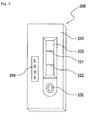
- Fig. 3 is a view illustrating a basic concept of the present invention.
- an analyte reaction result and an identification code are in the same side of an analyte kit 300.
- an analyte obtained from blood is provided to the analyte kit 300, moved by chromatography into a reaction area of the analyte kit 300, and reacted therein.
- the result of the reaction area is referred to as the analyte reaction result.
- the color of the reaction area changes according to a concentration of an analyte in the blood.
- the color may be the analyte reaction result.
- the analyte may be an antigen
- the analyte reaction result may be a result of an antigen-antibody reaction.
- the antigen may be Myoglobin, Creatine Kinase-MB(CK-MB), Troponin I, Pro-BNP, or D-dimer.
- the antigen may be a tumor marker.
- the tumor marker may be CA15-3 for metastatic breast cancer detection, CA19-9 9 for rectal cancer and pancreatic cancer detection, CA125 for ovarian cancer, CEA for rectal cancer, lung cancer, pancreatic cancer, gastrointestinal cancer, and breast cancer detection, PAS for prostate cancer detection, or AFP for liver cancer detection.
- an identification code means information including a separate code value required to obtain effective information about an analyte reaction result.
- the identification code may be manufacturing lot information about the analyte kit 300.
- the manufacturing lot information about the analyte kit 300 may be used to calibrate a result of reading an analyte reaction result.
- the identification code may be an expire date of the analyte kit 300.
- the identification code including the expire date is used to determine whether the analyte kit is to be used.
- the identification code may be implemented in various forms, such as bar code, color pattern, number, and character.
- the analyte kit 300 having an analyte reaction result and an identification code in one side thereof is photographed using a camera 310.
- An image photographed by the camera 310 is analyzed by a processor 320 and then the analysis result is output to an output unit 330.
- Fig. 4 is a view illustrating a first embodiment of an analyte kit according to the present invention.
- the analyte kit 300 includes an injection hole 330 for injecting an analyte, a display window 320 display an analysis result of the injected analyte, and an identification code 340.
- the display window 320 indicates an reaction area where an analyte is reacted.
- the display window 320, reaction area, and identification code should be in the same side.
- the display window 320 and the identification code 340 may be spaced apart by a certain interval.
- the identification code 340 exists in an area of the side of the analyte kit 300, which can be photographed by a camera.
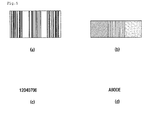
- the identification code 340 may be implemented in various methods, as shown in Pig. 5.
- barcode such as 1-dimensional barcode or 2-dimensional barcode, color pattern, numbers, or characters.
- Fig. 6 is a view illustrating an analyte kit according to a second embodiment of the present invention.
- a virtual area 600 is shown, which can be recognized by a camera in the analyte kit 300 having the identification code 340 marked thereon.
- the identification code 340 should be marked in the virtual area 600.
- the virtual area 600 may not be indicated. If necessary, the virtual area 600 may be indicated with a dotted line.
- the virtual area 600 may be recognized in various methods by an algorithm during a process of reading an analyte reaction result or identification code.
- a first virtual area 610 where an analyte reaction result of a display window 320 is photographed and a second virtual area 620 where an identification code is photographed are separated.
- the analyte reaction result may be read from the first virtual area 610 of a photographed image, and the identification code may be read from the second virtual area 620 thereof.
- the second virtual area 620 may be a remaining area in the photographed image, except the first virtual area 610.
- the first virtual area 610 and the second virtual area 620 may be recognized during a process by an algorithm even when there are no indications. And also, the areas may be indicated in a specific method.
- the process of reading the analyte reaction result may be different from the process of reading the code information according to an area division method of the analyte kit 300.
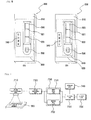
- Fig. 7 is a view illustrating a configuration of a device for quantitatively measuring an analyte by using a camera according to the present invention.
- the quantitative measurement device includes an image photographing unit 710, an image processing unit 720, a read unit 730, a storage unit 740, a control unit 750, and a output unit 760.
- the image photographing unit 710 may be generally a camera.
- the image photographing unit 710 photographs one side of the analyte kit 300 having an analyte reaction result and an identification code therein. In this case, the side of the analyte kit 300 is photographed at one time.
- the image processing unit 720 separates an analyte reaction result image and an identification code image from the image of the side of the analyte kit 300 which is photographed by the image photographing unit 710.
- the method of separating the analyte reaction result image and the identification code image may be implemented in various algorithms.
- the analyte reaction result image and the identification code image are separated according to their positions in a virtual area, as illustrated in Fig. 6(A) .
- a central portion may be recognized as the analyte reaction result image
- relatively an edge area may be recognized as the identification code area.
- the first virtual area 610 is recognized as the analyte reaction result area
- the second virtual area 620 is recognized as the identification code area.
- the first virtual area 610 and the second virtual area 620 may be predetermined in the image processing unit 720.
- the read unit 730 reads the analyte reaction result image and the identification code image, respectively.
- the read unit 730 may have a first read unit 731 for reading the analyte reaction result and a second read unit 732 for reading the code information.
- the control unit 750 allows the result of reading the analyte reaction result to be processed and then output by using the result of reading the identification code image.
- the control unit 750 may load information corresponding to the read identification code from the storage unit 740 storing information corresponding to identification codes and thus obtain effective information about the analyte.
- control unit 750 allows a result of reading the analyte reaction result to be calibrated using the manufacturing lot information which is read from the identification code.
- control unit 750 allows an error message to be output through the output unit 760 when the expire date has passed according to a result of reading the identification code photographed by the image photographing unit 710.
- control unit 750 allows an error message "unable to be analyzed" to be output through the output unit 760 when the analyte has the type which cannot be analyzed by the quantitative measurement device.
- the output unit 760 outputs an effective end result for an analyte which is obtained by the control unit 750.
- the output unit 760 may be referred to as various terms such as a display unit.
- the image photographing unit 710 photographs one side of the analyte kit having an analyte reaction result and an identification code therein in the order of a first image and a second image.
- the first image and the second image are the same or different with respect to a predetermined area.
- the first image may be used for the analyte reaction result, and the second image may be used for the identification code.
- the read unit 730 reads the analyte reaction result and the identification code from the first image and the second image, respectively, which are photographed by the image photographing unit 710.
- the read unit 730 may extract and read the analyte reaction result and the identification code from the predetermined first image and second image, respectively.
- the control unit 750 allows the result of reading the analyte reaction result to be processed and then output by using the result of reading the identification code image.
- the control unit 750 may load information corresponding to the read identification code from the storage unit 740 storing information corresponding to identification codes and thus obtain effective information about the analyte.
- the output unit 760 outputs an effective end result for an analyte which is obtained by the control unit 750.
- Fig. 8 is a view illustrating a method of quantitatively measuring an analyte by using a camera according to a first embodiment of the present invention.
- an analyte kit including an analyte reaction result and an identification code is photographed by an image photographing unit, i.e., a camera (S810).
- an analyte reaction result image included in a first area and an identification code image included in a second area are separated from the photographed image of the side of the analyte kit (S820).
- the first area and the second area may be predetermined.
- the analyte reaction result image and the identification code image are separated, the analyte reaction result of the first area is read (S830).
- a result of reading the analyte reaction result is analyzed using a result of reading the identification code, and then a reaction result is output (S850).
- analyzing the result of reading the analyte reaction result and then outputting the analysis result denotes loading information corresponding to the read identification code from a storage unit storing information corresponding to identification codes to obtain effective information about the analyte. After the effective information about the analyte is obtained, this information is output through an output unit (S860).
- the identification code includes manufacturing lot information about the analyte kit
- a result of reading the analyte reaction result is calibrated using the manufacturing lot information, and a result of reading the calibrated analyte reaction result is output.
- the identification code of the second area includes expire date information and is photographed by a camera before an analyte is injected, it is determined whether the expire date of the analyte kit included in the identification code has passed, and if the expire date has passed, an error message is output.
- the identification code includes analyte type information about types of analytes capable of being analyzed in the analyte kit and is photographed by a camera before the analyte is injected, if the analyte has the type which cannot be analyzed, an error message is output.
- Fig. 9 is a view illustrating a method of quantitatively measuring an analyte by using a camera according to a second embodiment of the present invention.
- an analyte kit including an analyte reaction result and an identification code is photographed in the order of a first image and a second image (S910, 5930) .
- the first image denotes a first area image
- the second image denotes a second area image.
- the analyte reaction result is read from the first image (S920).
- the identification code is read from the second area (S940).
- data corresponding to the identification code stored in a storage unit may be used.
- the cases where the identification code is the expire date information, the analyte type information, and the manufacturing lot information may be implemented through the processes of Fig. 8 .
Abstract
Description
- The present invention relates to a device, method, and system for quantitatively measuring an analyte, and more particularly, to a device, method, and system for quantitatively measuring an analyte by using a camera, which can read an identification code required to derive an accurate analysis result of an analyte while photographing an analyte reaction result by using a camera without additional equipment.
- In general, as interest in health increases, various technologies for physical health analysis using bio-samples are being introduced.
- From thereamong, using diagnostic kits allows an extremely small amount of bio-analytes to be analyzed, thereby easily checking health conditions.
- In this case, in order to analyze an end result as illustrated in
Fig. 1 , a result of an antigen-antibody reaction or enzyme reaction occurring in samples is provided through adiagnostic kit 10, and the result is photographed by acamera 20. - At this point, to obtain an accurate result, code information including effective information about respective diagnostic kits should be recognized.
- To recognize this code information, according to existing methods, codes are implemented in bar codes, and the code information is recognized using a barcode reader separately from a camera.
- Accordingly, as illustrated in
Fig. 2 , a reaction result is photographed using acamera 220, and acode 230 is read using abar code reader 240 separately. In another method, codes may be recognized using RFID units. - However, using typical bar code readers or RFID units needs additional equipment for reading codes separately from photographing a reaction result of a diagnostic kit, and thus the miniaturizing of an analyzer is difficult and also additional cost arises.
- Moreover, since additional operations of reading codes are needed, it takes more time for analysis and also operation processes are more complicated.
- The present invention provides a quantitative measurement device using a camera, which can obtain code information about an analyte kit as well as a sample reaction result through the photographing of images when analyzing the sample reaction result.
- The present invention also provides an analyte kit, which can have an image photographable area to analyze the sample reaction result and the code information of the analyte kit through the photographing of images.
- A quantitative measurement device using a camera according to a first embodiment of the present invention includes a camera photographing a camera recognition area in one side of an analyte kit, wherein the camera recognition area comprises an analyte reaction result obtained by reaction of the analyte in blood and an identification code of the analyte kit; an image processing unit separating the images of the analyte reaction result and identification code from an image of the camera recognition code of the analyte kit photographed by the camera; a read unit reading the images of the photographed analyte reaction result and identification code, and a control unit allowing a result of reading the image of the analyte reaction result to be processed by using a result of reading the image of the identification code.
- In this case, the read unit may include a first read unit reading the image of the analyte reaction result and a second read unit reading the image of the identification code.
- And also, in order to process the result of reading the image of the analyte reaction result, the quantitative measurement device may further comprise a storage unit storing data corresponding to the identification code.
- The result of reading the image of the analyte reaction result may be output through an output unit or display unit.
- A quantitative measurement device using a camera according to a second embodiment of the present invention includes a camera photographing a camera recognition area in one side of an analyte kit in the order of a first image and a second image, wherein the camera recognition area comprises an analyte reaction result obtained by reaction of the analyte in blood and an identification code of the analyte kit; a read unit reading the analyte reaction result and the identification code from the first image and the second image, respectively, which are photographed by the camera; and a control unit allowing a result of reading the image of the analyte reaction result to be processed by using a result of reading the image of the identification code.
- The read unit extracts and reads the analyte reaction result and the identification code from a first virtual area and a second virtual area, respectively, of the camera recognition area in one side of the analyte kit.
- The second virtual area may be a remaining area in the second image photographed by the camera, except the first virtual area.
- The identification code may include at least one of a bar code, color pattern code, character, or number.
- The identification code may include manufacturing lot information of the analyte kit, and the control unit may allow the result of reading the image of the analyte reaction result to be calibrated using the manufacturing lot information and allow the calibrated result to be output through a display unit.
- The identification code may include an expire date of the analyte kit. In this case, the camera photographs the identification code before the analyte of blood is injected, and the control unit allows an error message to be output if the expire date of the analyte kit has passed.
- The identification code may include analyte type information about types of analytes capable of being analyzed in the analyte kit. In this case, the camera photographs the identification code before the analyte of blood is injected, and the control unit allows an error message to be output if the analyte has the type which cannot be analyzed in the analyte kit.
- An analyte kit used in a quantitative measurement device for quantitatively measuring an analyte in blood by using a camera according to a third embodiment of the present invention includes a display window displaying an analyte reaction result obtained by reaction of the analyte in blood; and an identification code of the analyte kit, wherein the display window and the identification code are formed in a camera recognition area in one side of the analyte kit.
- The analyte may be an antigen, and the analyte reaction result may be a result of an antigen-antibody reaction. The antigen may be Myoglobin, Creatine Kinase-MB(CK-MB), Troponin I, Pro-BNP, or D-dimer.
- The antigen may be a tumor marker. For example, the tumor marker may be CA15-3 for metastatic breast cancer detection, CA19-9 for rectal cancer and pancreatic cancer detection, CA125 for ovarian cancer, CEA for rectal cancer, lung cancer, pancreatic cancer, gastrointestinal cancer, and breast cancer detection, PAS for prostate cancer detection, or AFP for liver cancer detection.
- The camera recognition area may include a first virtual area and a second virtual area, the first virtual area including the display window and the second virtual area including the identification code.
- The first virtual area and the second virtual area may be separated with a visible line.
- A quantitative measurement method using a camera according to a fourth embodiment of the present invention includes the steps of: photographing a camera recognition area in one side of an analyte kit by the camera, wherein the camera recognition area comprises an analyte reaction result obtained by reaction of the analyte in blood and an identification code of the analyte kit; separating the images of the analyte reaction result and identification code from an image of the camera recognition code of the analyte kit photographed by the camera; reading the images of the analyte reaction result and identification code, and processing a result of reading the image of the analyte reaction result by using a result of reading the image of the identification code.
- The processing may use the data corresponding to the identification code stored in the storage unit to process the result of reading the analyte reaction result.
- A quantitative measurement method using a camera according to a fifth embodiment of the present invention includes the first step of photographing a camera recognition area in one side of an analyte kit in the order of a first image and a second image by the camera, wherein the camera recognition area comprises an analyte reaction result obtained by reaction of the analyte in blood and an identification code of the analyte kit; the second step of reading the analyte reaction result from the first image; the third step of reading the identification code from the second image; and a fourth step of processing a result of reading the image of the analyte reaction result by using a result of reading the image of the identification code.
- A quantitative measurement system using a camera according to a sixth embodiment of the present invention includes: an analyte kit including a display window displaying an analyte reaction result obtained by reaction of the analyte in blood, and an identification code included in a camera recognition area which is in the same side as the display window; and the quantitative measurement device according to the first or second embodiment.
- As described above, the device and method for quantitatively measuring an analyte by using a camera according to the present invention can recognize an analyte reaction result and code information by using one camera, thereby analyzing a sample quickly and miniaturizing the device because there is no need to include a code recognition device separately.
- Furthermore, the device and method for quantitatively measuring an analyte by using a camera according to the present invention can recognize an analyte reaction result and code information by using one camera, thereby analyzing the recognized information with software.
-
Fig. 1 is a view of a system for quantitatively measuring an analyte in the related art. -
Fig. 2 is a view illustrating a concept of the prior art. -
Fig. 3 is a view illustrating a basic concept of the present invention. -
Fig. 4 is a view illustrating an analyte kit according to a first embodiment of the present invention. -
Fig. 5 is a view illustrating various methods of implementing identification codes according to the present invention. -
Fig. 6 is a view illustrating an analyte kit according to a second embodiment of the present invention. -
Fig. 7 is a view illustrating a configuration of a system for quantitatively measuring an analyte by using a camera according to the present invention. -
Fig. 8 is a view illustrating a method of quantitatively measuring an analyte by using a camera according to a first embodiment of the present invention. -
Fig. 9 is a view illustrating a method of quantitatively measuring an analyte by using a camera according to a second embodiment of the present invention. - Hereinafter, preferred embodiments will be described in more detail with reference to the accompanying drawings. Moreover, detailed descriptions related to well-known functions or configurations will be ruled out in order not to unnecessarily obscure subject matters of the present invention.
- In the description of the present invention, a "analyte" term is uniformly used as an analyte in a sample taken from an organism and then used for analysis, and a "analyte kit" term is uniformly used as a diagnostic kit. And also, an "identification code" term is uniformly used as a code including code information. However, technical features are not limited to these terms.
-
Fig. 3 is a view illustrating a basic concept of the present invention. - As illustrated in
Fig. 3 , in order to analyze an analyte through a quantitative measurement device according to the present invention, an analyte reaction result and an identification code are in the same side of ananalyte kit 300. - At this point, an analyte obtained from blood is provided to the
analyte kit 300, moved by chromatography into a reaction area of theanalyte kit 300, and reacted therein. The result of the reaction area is referred to as the analyte reaction result. - For example, blood is moved by chromatography into a reaction area and reacted therein, and thus the color of the reaction area changes according to a concentration of an analyte in the blood. At this point, the color may be the analyte reaction result.
- As a specific example, the analyte may be an antigen, and the analyte reaction result may be a result of an antigen-antibody reaction. Herein, the antigen may be Myoglobin, Creatine Kinase-MB(CK-MB), Troponin I, Pro-BNP, or D-dimer.
- And also, the antigen may be a tumor marker. For example, the tumor marker may be CA15-3 for metastatic breast cancer detection, CA19-9 9 for rectal cancer and pancreatic cancer detection, CA125 for ovarian cancer, CEA for rectal cancer, lung cancer, pancreatic cancer, gastrointestinal cancer, and breast cancer detection, PAS for prostate cancer detection, or AFP for liver cancer detection.
- However, this is just one example, and thus many analytes may be analyzed and analyte reaction results thereof may be various.
- And also, an identification code means information including a separate code value required to obtain effective information about an analyte reaction result.
- For example, the identification code may be manufacturing lot information about the
analyte kit 300. The manufacturing lot information about theanalyte kit 300 may be used to calibrate a result of reading an analyte reaction result. - As another example, the identification code may be an expire date of the
analyte kit 300. The identification code including the expire date is used to determine whether the analyte kit is to be used. - The identification code may be implemented in various forms, such as bar code, color pattern, number, and character.
- The
analyte kit 300 having an analyte reaction result and an identification code in one side thereof is photographed using acamera 310. An image photographed by thecamera 310 is analyzed by aprocessor 320 and then the analysis result is output to anoutput unit 330. -
Fig. 4 is a view illustrating a first embodiment of an analyte kit according to the present invention. - As illustrated in
FIG. 4 , theanalyte kit 300 includes aninjection hole 330 for injecting an analyte, adisplay window 320 display an analysis result of the injected analyte, and anidentification code 340. - In this case, the
display window 320 indicates an reaction area where an analyte is reacted. - To obtain an analyte analysis result using a camera, the
display window 320, reaction area, and identification code should be in the same side. - However since the camera reads the analyte reaction result and identification code separately, the
display window 320 and theidentification code 340 may be spaced apart by a certain interval. - And also, the
identification code 340 exists in an area of the side of theanalyte kit 300, which can be photographed by a camera. - The
identification code 340 may be implemented in various methods, as shown in Pig. 5. - For example, it may be implemented with a barcode such as 1-dimensional barcode or 2-dimensional barcode, color pattern, numbers, or characters.
-
Fig. 6 is a view illustrating an analyte kit according to a second embodiment of the present invention. - As illustrated in
Fig. 6(A) , avirtual area 600 is shown, which can be recognized by a camera in theanalyte kit 300 having theidentification code 340 marked thereon. - Accordingly, the
identification code 340 should be marked in thevirtual area 600. Herein, thevirtual area 600 may not be indicated. If necessary, thevirtual area 600 may be indicated with a dotted line. - However, the
virtual area 600 may be recognized in various methods by an algorithm during a process of reading an analyte reaction result or identification code. - In
Fig. 6(B) , a firstvirtual area 610 where an analyte reaction result of adisplay window 320 is photographed and a secondvirtual area 620 where an identification code is photographed are separated. - In this case, the analyte reaction result may be read from the first
virtual area 610 of a photographed image, and the identification code may be read from the secondvirtual area 620 thereof. The secondvirtual area 620 may be a remaining area in the photographed image, except the firstvirtual area 610. - Herein, the first
virtual area 610 and the secondvirtual area 620 may be recognized during a process by an algorithm even when there are no indications. And also, the areas may be indicated in a specific method. - Like this, the process of reading the analyte reaction result may be different from the process of reading the code information according to an area division method of the
analyte kit 300. -
Fig. 7 is a view illustrating a configuration of a device for quantitatively measuring an analyte by using a camera according to the present invention. - As illustrated in
FIG. 7 , the quantitative measurement device includes animage photographing unit 710, animage processing unit 720, aread unit 730, astorage unit 740, acontrol unit 750, and aoutput unit 760. Herein, theimage photographing unit 710 may be generally a camera. - The
image photographing unit 710 photographs one side of theanalyte kit 300 having an analyte reaction result and an identification code therein. In this case, the side of theanalyte kit 300 is photographed at one time. - The
image processing unit 720 separates an analyte reaction result image and an identification code image from the image of the side of theanalyte kit 300 which is photographed by theimage photographing unit 710. - The method of separating the analyte reaction result image and the identification code image may be implemented in various algorithms.
- For example, the analyte reaction result image and the identification code image are separated according to their positions in a virtual area, as illustrated in
Fig. 6(A) . In a photographed image, a central portion may be recognized as the analyte reaction result image, and relatively an edge area may be recognized as the identification code area. - As another example, in a case where the
analyte kit 300 has the firstvirtual area 610 and the secondvirtual area 620 as illustrated inFig. 6(B) , the firstvirtual area 610 is recognized as the analyte reaction result area, and the secondvirtual area 620 is recognized as the identification code area. The firstvirtual area 610 and the secondvirtual area 620 may be predetermined in theimage processing unit 720. - The
read unit 730 reads the analyte reaction result image and the identification code image, respectively. - The
read unit 730 may have afirst read unit 731 for reading the analyte reaction result and asecond read unit 732 for reading the code information. - The
control unit 750 allows the result of reading the analyte reaction result to be processed and then output by using the result of reading the identification code image. In this case, thecontrol unit 750 may load information corresponding to the read identification code from thestorage unit 740 storing information corresponding to identification codes and thus obtain effective information about the analyte. - In particular, when the identification code is manufacturing lot information about the analyte kit, the
control unit 750 allows a result of reading the analyte reaction result to be calibrated using the manufacturing lot information which is read from the identification code. - When the identification code is an expire date, the
control unit 750 allows an error message to be output through theoutput unit 760 when the expire date has passed according to a result of reading the identification code photographed by theimage photographing unit 710. - And also, in a case where the identification code indicates a type of an analyte to be analyzed in an analyte kit, the
control unit 750 allows an error message "unable to be analyzed" to be output through theoutput unit 760 when the analyte has the type which cannot be analyzed by the quantitative measurement device. - The
output unit 760 outputs an effective end result for an analyte which is obtained by thecontrol unit 750. Depending on the case, theoutput unit 760 may be referred to as various terms such as a display unit. - As another method, the
image photographing unit 710 photographs one side of the analyte kit having an analyte reaction result and an identification code therein in the order of a first image and a second image. - In this case, the first image and the second image are the same or different with respect to a predetermined area.
- The first image may be used for the analyte reaction result, and the second image may be used for the identification code.
- The
read unit 730 reads the analyte reaction result and the identification code from the first image and the second image, respectively, which are photographed by theimage photographing unit 710. - In this case, the
read unit 730 may extract and read the analyte reaction result and the identification code from the predetermined first image and second image, respectively. - The
control unit 750 allows the result of reading the analyte reaction result to be processed and then output by using the result of reading the identification code image. In this case, thecontrol unit 750 may load information corresponding to the read identification code from thestorage unit 740 storing information corresponding to identification codes and thus obtain effective information about the analyte. - The
output unit 760 outputs an effective end result for an analyte which is obtained by thecontrol unit 750. -
Fig. 8 is a view illustrating a method of quantitatively measuring an analyte by using a camera according to a first embodiment of the present invention. - As illustrated in
Fig. 8 , in the method of quantitatively measuring an analyte by using a camera according to a first embodiment of the present invention, one side of an analyte kit including an analyte reaction result and an identification code is photographed by an image photographing unit, i.e., a camera (S810). - After the side of the analyte kit is photographed, an analyte reaction result image included in a first area and an identification code image included in a second area are separated from the photographed image of the side of the analyte kit (S820). In this case, the first area and the second area may be predetermined.
- After the analyte reaction result image and the identification code image are separated, the analyte reaction result of the first area is read (S830).
- And also, the identification code of the second area is read (S840).
- After the analyte reaction result and the identification code are read, a result of reading the analyte reaction result is analyzed using a result of reading the identification code, and then a reaction result is output (S850). In this case, analyzing the result of reading the analyte reaction result and then outputting the analysis result denotes loading information corresponding to the read identification code from a storage unit storing information corresponding to identification codes to obtain effective information about the analyte. After the effective information about the analyte is obtained, this information is output through an output unit (S860).
- For example, in a case where the identification code includes manufacturing lot information about the analyte kit, a result of reading the analyte reaction result is calibrated using the manufacturing lot information, and a result of reading the calibrated analyte reaction result is output.
- In a case where the identification code of the second area includes expire date information and is photographed by a camera before an analyte is injected, it is determined whether the expire date of the analyte kit included in the identification code has passed, and if the expire date has passed, an error message is output.
- And also, in a case where the identification code includes analyte type information about types of analytes capable of being analyzed in the analyte kit and is photographed by a camera before the analyte is injected, if the analyte has the type which cannot be analyzed, an error message is output.
-
Fig. 9 is a view illustrating a method of quantitatively measuring an analyte by using a camera according to a second embodiment of the present invention. - As illustrated in
Fig. 9 , in the method of quantitatively measuring an analyte by using a camera according to a second embodiment of the present invention, one side of an analyte kit including an analyte reaction result and an identification code is photographed in the order of a first image and a second image (S910, 5930) . In this case, the first image denotes a first area image, and the second image denotes a second area image. - After the first image and the second image are photographed, the analyte reaction result is read from the first image (S920).
- And also, the identification code is read from the second area (S940).
- Accordingly, after the first image and the second image are photographed, a result of reading the analyte reaction result is analyzed using a result of reading of the identification code image, and then an analysis result is generated (S950).
- In this case, in order to analyze the result of reading the analyte reaction result, data corresponding to the identification code stored in a storage unit may be used.
- And then, the generated reaction result, i.e., effective information about the analyte is output (S960).
- In particular, the cases where the identification code is the expire date information, the analyte type information, and the manufacturing lot information may be implemented through the processes of
Fig. 8 . - While the invention has been particularly shown and described with reference to exemplary embodiments thereof, it will be understood that various changes in form and details may be made therein without departing from the spirit and scope of the following claims.
Claims (20)
- A quantitative analyte measurement device for quantitatively measuring an analyte in blood, the quantitative analyte measurement device comprising:a camera photographing a camera recognition area in one side of an analyte kit, wherein the camera recognition area comprises an analyte reaction result obtained by reaction of the analyte in blood and an identification code of the analyte kit; anda read unit reading images of the photographed analyte reaction result and identification code.
- The quantitative analyte measurement device of claim 1, further comprising a control unit allowing a result of reading the image of the analyte reaction result to be processed using a result of reading the image of the identification code.
- The quantitative analyte measurement device of claim 1, wherein the camera photographs the analyte reaction result and the identification code at one time, and
the quantitative analyte measurement device further comprises an image processing unit separating the images of the analyte reaction result and identification code photographed by the camera from each other. - The quantitative analyte measurement device of claim 1, wherein the camera photographs the analyte reaction result and the identification code in the order of a first image and a second image, and
the read unit reads the analyte reaction result and the identification code from the first image and the second image, respectively. - The quantitative analyte measurement device of claim 1, wherein the identification code comprises at least one of a bar code, color pattern code, character, or number.
- The quantitative analyte measurement device of claim 2, wherein the identification code comprises manufacturing lot information of the analyte kit, and
the control unit allows the result of reading the image of the analyte reaction result to be calibrated using the manufacturing lot information. - The quantitative analyte measurement device of claim 1, wherein the identification code comprises an expire date of the analyte kit,
the camera photographs the identification code before the analyte of blood is injected, and
the quantitative analyte measurement device further comprises a control unit allowing an error message to be output if the expire date of the analyte kit has passed. - The quantitative analyte measurement device of claim 1, wherein the identification code comprises analyte type information about types of analytes capable of being analyzed in the analyte kit,
the camera photographs the identification code before the analyte of blood is injected, and
the quantitative analyte measurement device further comprises a control unit allowing an error message to be output if the analyte has the type which cannot be analyzed in the analyte kit. - The quantitative analyte measurement device of claim 4, wherein the read unit extracts and reads the analyte reaction result and the identification code from a first virtual area and a second virtual area, respectively, of the camera recognition area in one side of the analyte kit.
- A quantitative analyte measurement method of quantitatively measuring an analyte in blood by using a camera, the quantitative analyte measurement method comprising:photographing a camera recognition area in one side of an analyte kit by a camera wherein the camera recognition area comprises an analyte reaction result obtained by reaction of the analyte in blood and an identification code of the analyte kit; andreading images of the photographed analyte reaction result and identification code, respectively.
- The quantitative analyte measurement method of claim 10, further comprising processing a result of reading the image of the analyte reaction result by using a result of reading the image of the identification code.
- The quantitative analyte measurement method of claim 10, wherein the photographing comprises photographing the analyte reaction result and the identification code at one time, and
the quantitative analyte measurement method further comprises separating the images of the photographed analyte reaction result and identification code from each other. - The quantitative analyte measurement method of claim 10, wherein the photographing comprises photographing the analyte reaction result and the identification code in the order of a first image and a second image, and
the reading comprises reading the analyte reaction result and the identification code from the first image and the second image, respectively. - The quantitative analyte measurement method of claim 11, wherein the identification code comprises manufacturing lot information of the analyte kit, and
the processing comprises calibrating the result of reading the image of the analyte reaction result by using the manufacturing lot information. - The quantitative analyte measurement method of claim 10, wherein the identification code comprises an expire date of the analyte kit, and
the quantitative analyte measurement method further comprises:photographing the identification code before the analyte of blood is injected; andoutputting an error message if the expire date of the analyte kit has passed. - The quantitative analyte measurement method of claim 10, wherein the identification code comprises analyte type information about types of analytes capable of being analyzed in the analyte kit,
the quantitative analyte measurement method further comprises: photographing the identification code by the camera before the analyte of blood is injected; and
outputting an error message if the analyte has the type which cannot be analyzed in the analyte kit. - An analyte kit used in a quantitative analyte measurement device for quantitatively measuring an analyte in blood by using a camera, the analyte kit comprises:a display window displaying an analyte reaction result obtained by reaction of the analyte in blood; andan identification code of the analyte kit,wherein the display window and the identification code are formed in a camera recognition area in one side of the analyte kit.
- The analyte kit of claim 17, wherein the camera recognition area comprises a first virtual area and a second virtual area, the first virtual area comprising the display window and the second virtual area comprising the identification code.
- The analyte kit of claim 17, wherein the identification code comprises at least one of manufacturing lot information, an expire date, and analyte type information about types of analytes capable of being analyzed.
- A quantitative analyte measurement system of quantitatively measuring an analyte in blood, the quantitative measurement system comprising:the quantitative analyte measurement device according to claim 1; andthe analyte kit according to claim 17.
Applications Claiming Priority (2)
| Application Number | Priority Date | Filing Date | Title |
|---|---|---|---|
| KR1020090082869A KR101044556B1 (en) | 2009-09-03 | 2009-09-03 | Apparatus, method and system for performing quantitative measurement of sample using camera |
| PCT/KR2010/005823 WO2011028000A2 (en) | 2009-09-03 | 2010-08-30 | Device, method, and system for quantitatively measuring a specimen using a camera |
Publications (3)
| Publication Number | Publication Date |
|---|---|
| EP2474828A2 true EP2474828A2 (en) | 2012-07-11 |
| EP2474828A4 EP2474828A4 (en) | 2014-05-07 |
| EP2474828B1 EP2474828B1 (en) | 2018-08-08 |
Family
ID=43649761
Family Applications (1)
| Application Number | Title | Priority Date | Filing Date |
|---|---|---|---|
| EP10813909.8A Active EP2474828B1 (en) | 2009-09-03 | 2010-08-30 | Device and method for quantitatively measuring a specimen using a camera |
Country Status (8)
| Country | Link |
|---|---|
| US (2) | US20120178101A1 (en) |
| EP (1) | EP2474828B1 (en) |
| JP (1) | JP5692707B2 (en) |
| KR (1) | KR101044556B1 (en) |
| CN (1) | CN102549426A (en) |
| IN (1) | IN2012DN02611A (en) |
| RU (1) | RU2519644C2 (en) |
| WO (1) | WO2011028000A2 (en) |
Cited By (1)
| Publication number | Priority date | Publication date | Assignee | Title |
|---|---|---|---|---|
| CN103675257A (en) * | 2012-08-31 | 2014-03-26 | 英佛皮亚有限公司 | Case for specimen analyzing kit, kit for specimen analyzing, specimen analysis apparatus and control method of specimen analysis apparatus |
Families Citing this family (20)
| Publication number | Priority date | Publication date | Assignee | Title |
|---|---|---|---|---|
| JP5482721B2 (en) * | 2011-04-22 | 2014-05-07 | ウシオ電機株式会社 | Analysis equipment |
| JP5267617B2 (en) | 2011-06-23 | 2013-08-21 | ウシオ電機株式会社 | Analysis apparatus and analysis method |
| US9285323B2 (en) | 2012-08-08 | 2016-03-15 | Scanadu Incorporated | Quantifying color changes of chemical test pads induced concentrations of biological analytes under different lighting conditions |
| US10983065B2 (en) | 2012-08-08 | 2021-04-20 | Healthy.Io Ltd. | Method, apparatus and system for detecting and determining compromised reagent pads by quantifying color changes induced by exposure to a hostile environment |
| KR101402382B1 (en) * | 2012-08-31 | 2014-06-03 | 주식회사 인포피아 | Specimen analysis apparatus |
| KR101388834B1 (en) * | 2012-08-31 | 2014-04-30 | 주식회사 인포피아 | Specimen analysis apparatus |
| KR101494526B1 (en) * | 2013-06-11 | 2015-02-23 | 주식회사 인포피아 | Specimen analysis apparatus and control method thereof |
| KR101388691B1 (en) | 2012-08-31 | 2014-04-25 | 주식회사 인포피아 | Specimen analysis apparatus |
| KR101388841B1 (en) * | 2012-08-31 | 2014-04-24 | 주식회사 인포피아 | Specimen analysis apparatus |
| GB201221015D0 (en) | 2012-11-22 | 2013-01-09 | Microlab Devices Ltd | Test strip nd methods and apparatus for reading the same |
| US11030778B2 (en) | 2014-03-31 | 2021-06-08 | Healthy.Io Ltd. | Methods and apparatus for enhancing color vision and quantifying color interpretation |
| WO2015156429A1 (en) * | 2014-04-08 | 2015-10-15 | 주식회사 수젠텍 | Method and system for measuring test strip |
| US10991096B2 (en) | 2014-05-12 | 2021-04-27 | Healthy.Io Ltd. | Utilizing personal communications devices for medical testing |
| US11087467B2 (en) | 2014-05-12 | 2021-08-10 | Healthy.Io Ltd. | Systems and methods for urinalysis using a personal communications device |
| WO2016024808A1 (en) * | 2014-08-12 | 2016-02-18 | Samsung Electronics Co., Ltd. | In-vitro diagnostic apparatus and in-vitro diagnostic method performed by in-vitro diagnostic apparatus |
| WO2016025935A2 (en) | 2014-08-15 | 2016-02-18 | Scanadu Incorporated | Precision luxmeter methods for digital cameras to quantify colors in uncontrolled lighting environments |
| CN108229236B (en) * | 2017-12-29 | 2021-10-22 | 苏州德创测控科技有限公司 | Code reading system and code reading method |
| CN108398179A (en) * | 2018-02-24 | 2018-08-14 | 上海康斐信息技术有限公司 | A kind of meausring apparatus detection method and system |
| US20200209214A1 (en) | 2019-01-02 | 2020-07-02 | Healthy.Io Ltd. | Urinalysis testing kit with encoded data |
| KR102347364B1 (en) * | 2020-10-22 | 2022-01-07 | 주식회사 로그인서광 | Diagnostic Kit Reader and Avian Influenza Alarm System Including The Same |
Citations (6)
| Publication number | Priority date | Publication date | Assignee | Title |
|---|---|---|---|---|
| EP0646784A1 (en) * | 1993-09-07 | 1995-04-05 | Bayer Corporation | Video test strip reader and method for evaluating test strips |
| EP1391728A1 (en) * | 2002-08-21 | 2004-02-25 | Lifescan, Inc. | Method and apparatus for assigning calibration codes to diagnostic test strips on the basis of calibration parameters |
| US20040096363A1 (en) * | 2002-11-18 | 2004-05-20 | Larry Porter | Point-of-care assay reader and analyzer |
| US20070081920A1 (en) * | 2005-10-12 | 2007-04-12 | Murphy R S | Semi-disposable optoelectronic rapid diagnostic test system |
| US20080019596A1 (en) * | 2004-09-16 | 2008-01-24 | Koninklijke Philips Electronics, N.V. | Imaging Method and Apparatus for Analysing Objects |
| US7344081B2 (en) * | 2003-05-22 | 2008-03-18 | Transpacific Ip, Ltd. | Method of automatically detecting a test result of a probe zone of a test strip |
Family Cites Families (23)
| Publication number | Priority date | Publication date | Assignee | Title |
|---|---|---|---|---|
| JPS63236966A (en) * | 1987-03-25 | 1988-10-03 | Shimadzu Corp | Automatic sample conveying device |
| US5126952A (en) * | 1991-01-22 | 1992-06-30 | Eastman Kodak Company | Bar coding calibration |
| US5223219A (en) * | 1992-04-10 | 1993-06-29 | Biotrack, Inc. | Analytical cartridge and system for detecting analytes in liquid samples |
| KR19980039325A (en) * | 1996-11-27 | 1998-08-17 | 민병구 | Test kit for platelet disorders, test method and sensor |
| JPH10170515A (en) | 1996-12-09 | 1998-06-26 | Takao Tsuda | Blood-compatibility observation apparatus |
| KR20010017092A (en) * | 1999-08-07 | 2001-03-05 | 김판구 | Method for counting and analyzing morphology of blood cell automatically |
| JP2001349834A (en) * | 2000-06-09 | 2001-12-21 | Hirose Denshi System Kk | Colored matter determining device |
| KR20020032752A (en) * | 2000-10-27 | 2002-05-04 | 김희태 | A method for detecting several target materials simultaneously by the multiple immune reaction and a kit therefor |
| US7267799B1 (en) * | 2002-08-14 | 2007-09-11 | Detekt Biomedical, L.L.C. | Universal optical imaging and processing system |
| JP2004152147A (en) * | 2002-10-31 | 2004-05-27 | Fujitsu Ltd | Bar code reader and bar code reading control method |
| JP2004212216A (en) * | 2002-12-27 | 2004-07-29 | Teruaki Ito | Specimen detection device |
| US7887750B2 (en) * | 2004-05-05 | 2011-02-15 | Bayer Healthcare Llc | Analytical systems, devices, and cartridges therefor |
| CN1773288A (en) * | 2004-11-09 | 2006-05-17 | 盛进生物工程(深圳)有限公司 | Sidestream analytic system and method |
| JP2006266882A (en) * | 2005-03-24 | 2006-10-05 | Jokoh Co Ltd | Immunological chromatograph reading/quantifying apparatus with function for reading expiration date information |
| JP4802925B2 (en) * | 2005-08-19 | 2011-10-26 | パナソニック株式会社 | Analytical device and analytical apparatus using the same |
| KR100680267B1 (en) * | 2005-09-16 | 2007-02-08 | 주식회사 인포피아 | Biosensor had the identification information and reading apparatus for the identification information recorded a biosensor |
| CN101379386B (en) * | 2005-12-22 | 2013-09-25 | 霍尼韦尔国际公司 | Portable sample analyzer system |
| EP1826705A1 (en) * | 2006-02-25 | 2007-08-29 | F.Hoffmann-La Roche Ag | Analytical consumables and arrangement for reading information |
| WO2008083323A1 (en) * | 2006-12-29 | 2008-07-10 | Invitrogen Corporation | Detection apparatus |
| WO2008121239A1 (en) * | 2007-03-29 | 2008-10-09 | Response Biomedical Corporation | Modular assay reader system and apparatus |
| EP3613338B1 (en) * | 2007-08-30 | 2021-04-28 | Siemens Healthcare Diagnostics Inc. | Non-visible detectable marking for medical diagnostics |
| JP2009150856A (en) * | 2007-12-25 | 2009-07-09 | Panasonic Corp | Method and apparatus for sample analysis and test piece |
| CN201203611Y (en) * | 2008-05-30 | 2009-03-04 | 王海波 | Full-automatic operational instrument for excrement conventional check |
-
2009
- 2009-09-03 KR KR1020090082869A patent/KR101044556B1/en active IP Right Grant
-
2010
- 2010-08-30 JP JP2012527817A patent/JP5692707B2/en active Active
- 2010-08-30 CN CN2010800396009A patent/CN102549426A/en active Pending
- 2010-08-30 US US13/393,989 patent/US20120178101A1/en not_active Abandoned
- 2010-08-30 RU RU2012112814/15A patent/RU2519644C2/en active
- 2010-08-30 EP EP10813909.8A patent/EP2474828B1/en active Active
- 2010-08-30 WO PCT/KR2010/005823 patent/WO2011028000A2/en active Application Filing
- 2010-08-30 IN IN2611DEN2012 patent/IN2012DN02611A/en unknown
-
2017
- 2017-07-06 US US15/642,855 patent/US20170299523A1/en not_active Abandoned
Patent Citations (6)
| Publication number | Priority date | Publication date | Assignee | Title |
|---|---|---|---|---|
| EP0646784A1 (en) * | 1993-09-07 | 1995-04-05 | Bayer Corporation | Video test strip reader and method for evaluating test strips |
| EP1391728A1 (en) * | 2002-08-21 | 2004-02-25 | Lifescan, Inc. | Method and apparatus for assigning calibration codes to diagnostic test strips on the basis of calibration parameters |
| US20040096363A1 (en) * | 2002-11-18 | 2004-05-20 | Larry Porter | Point-of-care assay reader and analyzer |
| US7344081B2 (en) * | 2003-05-22 | 2008-03-18 | Transpacific Ip, Ltd. | Method of automatically detecting a test result of a probe zone of a test strip |
| US20080019596A1 (en) * | 2004-09-16 | 2008-01-24 | Koninklijke Philips Electronics, N.V. | Imaging Method and Apparatus for Analysing Objects |
| US20070081920A1 (en) * | 2005-10-12 | 2007-04-12 | Murphy R S | Semi-disposable optoelectronic rapid diagnostic test system |
Non-Patent Citations (1)
| Title |
|---|
| See also references of WO2011028000A2 * |
Cited By (4)
| Publication number | Priority date | Publication date | Assignee | Title |
|---|---|---|---|---|
| CN103675257A (en) * | 2012-08-31 | 2014-03-26 | 英佛皮亚有限公司 | Case for specimen analyzing kit, kit for specimen analyzing, specimen analysis apparatus and control method of specimen analysis apparatus |
| EP2703804A3 (en) * | 2012-08-31 | 2014-05-07 | Infopia Co., Ltd. | Case for specimen analyzing kit, kit for specimen analyzing, specimen analysis apparatus and control method of specimen analysis apparatus |
| EP2703803A3 (en) * | 2012-08-31 | 2014-05-07 | Infopia Co., Ltd. | Case for specimen analyzing kit, kit for specimen analyzing, specimen analysis apparatus and control method of specimen analysis apparatus |
| US9714903B2 (en) | 2012-08-31 | 2017-07-25 | Osang Healthcare Co., Ltd. | Case for specimen analyzing kit, kit for specimen analyzing, specimen analysis apparatus and control method of specimen analysis apparatus |
Also Published As
| Publication number | Publication date |
|---|---|
| US20170299523A1 (en) | 2017-10-19 |
| IN2012DN02611A (en) | 2015-09-04 |
| WO2011028000A3 (en) | 2011-07-07 |
| RU2012112814A (en) | 2013-10-10 |
| US20120178101A1 (en) | 2012-07-12 |
| JP2013504060A (en) | 2013-02-04 |
| RU2519644C2 (en) | 2014-06-20 |
| KR20110024747A (en) | 2011-03-09 |
| CN102549426A (en) | 2012-07-04 |
| WO2011028000A2 (en) | 2011-03-10 |
| KR101044556B1 (en) | 2011-06-28 |
| EP2474828A4 (en) | 2014-05-07 |
| JP5692707B2 (en) | 2015-04-01 |
| EP2474828B1 (en) | 2018-08-08 |
Similar Documents
| Publication | Publication Date | Title |
|---|---|---|
| EP2474828B1 (en) | Device and method for quantitatively measuring a specimen using a camera | |
| EP2923335B1 (en) | Test strip and methods and apparatus for reading the same | |
| US8655009B2 (en) | Method and apparatus for performing color-based reaction testing of biological materials | |
| US11189056B2 (en) | Methods and devices for performing an analytical measurement based on a color formation reaction | |
| KR101539016B1 (en) | Immunoassay analysis method | |
| CN107862350B (en) | Test paper detection method, device, system and program product | |
| US7679740B2 (en) | Method and apparatus for multimodal detection | |
| CN104969068A (en) | Method and apparatus for performing and quantifying color changes induced by specific concentrations of biological analytes in an automatically calibrated environment | |
| US7990532B2 (en) | Method and apparatus for multimodal detection | |
| EP3477286B1 (en) | Methods and devices for performing an analytical measurement | |
| US20130327129A1 (en) | Spectroscopic sample inspection for automated chromatography | |
| TW201514861A (en) | Inspection cartridge reading device and reading method thereof | |
| JP2008241517A (en) | Sample analyzer | |
| KR101388834B1 (en) | Specimen analysis apparatus | |
| US20070111301A1 (en) | Biological information inspection system | |
| EP3954990B1 (en) | Test strip fixation device for optical measurements of an analyte | |
| WO2022196481A1 (en) | Sample image registration method, computer program, and storage medium | |
| JP2005291795A (en) | Fluorescence detection device and image processing system | |
| KR20210012740A (en) | Multiplexing blot assay automation system |
Legal Events
| Date | Code | Title | Description |
|---|---|---|---|
| PUAI | Public reference made under article 153(3) epc to a published international application that has entered the european phase |
Free format text: ORIGINAL CODE: 0009012 |
|
| 17P | Request for examination filed |
Effective date: 20120329 |
|
| AK | Designated contracting states |
Kind code of ref document: A2 Designated state(s): AL AT BE BG CH CY CZ DE DK EE ES FI FR GB GR HR HU IE IS IT LI LT LU LV MC MK MT NL NO PL PT RO SE SI SK SM TR |
|
| DAX | Request for extension of the european patent (deleted) | ||
| A4 | Supplementary search report drawn up and despatched |
Effective date: 20140408 |
|
| RIC1 | Information provided on ipc code assigned before grant |
Ipc: G01N 21/84 20060101ALI20140402BHEP Ipc: G01N 33/50 20060101AFI20140402BHEP Ipc: G01N 33/53 20060101ALI20140402BHEP |
|
| RAP1 | Party data changed (applicant data changed or rights of an application transferred) |
Owner name: OSANG HEALTHCARE CO., LTD. |
|
| GRAP | Despatch of communication of intention to grant a patent |
Free format text: ORIGINAL CODE: EPIDOSNIGR1 |
|
| STAA | Information on the status of an ep patent application or granted ep patent |
Free format text: STATUS: GRANT OF PATENT IS INTENDED |
|
| INTG | Intention to grant announced |
Effective date: 20180227 |
|
| GRAS | Grant fee paid |
Free format text: ORIGINAL CODE: EPIDOSNIGR3 |
|
| GRAA | (expected) grant |
Free format text: ORIGINAL CODE: 0009210 |
|
| STAA | Information on the status of an ep patent application or granted ep patent |
Free format text: STATUS: THE PATENT HAS BEEN GRANTED |
|
| AK | Designated contracting states |
Kind code of ref document: B1 Designated state(s): AL AT BE BG CH CY CZ DE DK EE ES FI FR GB GR HR HU IE IS IT LI LT LU LV MC MK MT NL NO PL PT RO SE SI SK SM TR |
|
| REG | Reference to a national code |
Ref country code: GB Ref legal event code: FG4D |
|
| REG | Reference to a national code |
Ref country code: CH Ref legal event code: EP Ref country code: AT Ref legal event code: REF Ref document number: 1027602 Country of ref document: AT Kind code of ref document: T Effective date: 20180815 |
|
| REG | Reference to a national code |
Ref country code: FR Ref legal event code: PLFP Year of fee payment: 9 |
|
| REG | Reference to a national code |
Ref country code: IE Ref legal event code: FG4D |
|
| REG | Reference to a national code |
Ref country code: DE Ref legal event code: R096 Ref document number: 602010052621 Country of ref document: DE |
|
| REG | Reference to a national code |
Ref country code: NL Ref legal event code: MP Effective date: 20180808 |
|
| REG | Reference to a national code |
Ref country code: LT Ref legal event code: MG4D |
|
| REG | Reference to a national code |
Ref country code: AT Ref legal event code: MK05 Ref document number: 1027602 Country of ref document: AT Kind code of ref document: T Effective date: 20180808 |
|
| PG25 | Lapsed in a contracting state [announced via postgrant information from national office to epo] |
Ref country code: FI Free format text: LAPSE BECAUSE OF FAILURE TO SUBMIT A TRANSLATION OF THE DESCRIPTION OR TO PAY THE FEE WITHIN THE PRESCRIBED TIME-LIMIT Effective date: 20180808 Ref country code: SE Free format text: LAPSE BECAUSE OF FAILURE TO SUBMIT A TRANSLATION OF THE DESCRIPTION OR TO PAY THE FEE WITHIN THE PRESCRIBED TIME-LIMIT Effective date: 20180808 Ref country code: IS Free format text: LAPSE BECAUSE OF FAILURE TO SUBMIT A TRANSLATION OF THE DESCRIPTION OR TO PAY THE FEE WITHIN THE PRESCRIBED TIME-LIMIT Effective date: 20181208 Ref country code: NL Free format text: LAPSE BECAUSE OF FAILURE TO SUBMIT A TRANSLATION OF THE DESCRIPTION OR TO PAY THE FEE WITHIN THE PRESCRIBED TIME-LIMIT Effective date: 20180808 Ref country code: PL Free format text: LAPSE BECAUSE OF FAILURE TO SUBMIT A TRANSLATION OF THE DESCRIPTION OR TO PAY THE FEE WITHIN THE PRESCRIBED TIME-LIMIT Effective date: 20180808 Ref country code: GR Free format text: LAPSE BECAUSE OF FAILURE TO SUBMIT A TRANSLATION OF THE DESCRIPTION OR TO PAY THE FEE WITHIN THE PRESCRIBED TIME-LIMIT Effective date: 20181109 Ref country code: LT Free format text: LAPSE BECAUSE OF FAILURE TO SUBMIT A TRANSLATION OF THE DESCRIPTION OR TO PAY THE FEE WITHIN THE PRESCRIBED TIME-LIMIT Effective date: 20180808 Ref country code: NO Free format text: LAPSE BECAUSE OF FAILURE TO SUBMIT A TRANSLATION OF THE DESCRIPTION OR TO PAY THE FEE WITHIN THE PRESCRIBED TIME-LIMIT Effective date: 20181108 Ref country code: BG Free format text: LAPSE BECAUSE OF FAILURE TO SUBMIT A TRANSLATION OF THE DESCRIPTION OR TO PAY THE FEE WITHIN THE PRESCRIBED TIME-LIMIT Effective date: 20181108 Ref country code: AT Free format text: LAPSE BECAUSE OF FAILURE TO SUBMIT A TRANSLATION OF THE DESCRIPTION OR TO PAY THE FEE WITHIN THE PRESCRIBED TIME-LIMIT Effective date: 20180808 |
|
| PG25 | Lapsed in a contracting state [announced via postgrant information from national office to epo] |
Ref country code: AL Free format text: LAPSE BECAUSE OF FAILURE TO SUBMIT A TRANSLATION OF THE DESCRIPTION OR TO PAY THE FEE WITHIN THE PRESCRIBED TIME-LIMIT Effective date: 20180808 Ref country code: HR Free format text: LAPSE BECAUSE OF FAILURE TO SUBMIT A TRANSLATION OF THE DESCRIPTION OR TO PAY THE FEE WITHIN THE PRESCRIBED TIME-LIMIT Effective date: 20180808 Ref country code: LV Free format text: LAPSE BECAUSE OF FAILURE TO SUBMIT A TRANSLATION OF THE DESCRIPTION OR TO PAY THE FEE WITHIN THE PRESCRIBED TIME-LIMIT Effective date: 20180808 |
|
| REG | Reference to a national code |
Ref country code: CH Ref legal event code: PL |
|
| PG25 | Lapsed in a contracting state [announced via postgrant information from national office to epo] |
Ref country code: LU Free format text: LAPSE BECAUSE OF NON-PAYMENT OF DUE FEES Effective date: 20180830 Ref country code: CH Free format text: LAPSE BECAUSE OF NON-PAYMENT OF DUE FEES Effective date: 20180831 Ref country code: ES Free format text: LAPSE BECAUSE OF FAILURE TO SUBMIT A TRANSLATION OF THE DESCRIPTION OR TO PAY THE FEE WITHIN THE PRESCRIBED TIME-LIMIT Effective date: 20180808 Ref country code: EE Free format text: LAPSE BECAUSE OF FAILURE TO SUBMIT A TRANSLATION OF THE DESCRIPTION OR TO PAY THE FEE WITHIN THE PRESCRIBED TIME-LIMIT Effective date: 20180808 Ref country code: LI Free format text: LAPSE BECAUSE OF NON-PAYMENT OF DUE FEES Effective date: 20180831 Ref country code: RO Free format text: LAPSE BECAUSE OF FAILURE TO SUBMIT A TRANSLATION OF THE DESCRIPTION OR TO PAY THE FEE WITHIN THE PRESCRIBED TIME-LIMIT Effective date: 20180808 Ref country code: IT Free format text: LAPSE BECAUSE OF FAILURE TO SUBMIT A TRANSLATION OF THE DESCRIPTION OR TO PAY THE FEE WITHIN THE PRESCRIBED TIME-LIMIT Effective date: 20180808 Ref country code: CZ Free format text: LAPSE BECAUSE OF FAILURE TO SUBMIT A TRANSLATION OF THE DESCRIPTION OR TO PAY THE FEE WITHIN THE PRESCRIBED TIME-LIMIT Effective date: 20180808 |
|
| REG | Reference to a national code |
Ref country code: DE Ref legal event code: R097 Ref document number: 602010052621 Country of ref document: DE |
|
| REG | Reference to a national code |
Ref country code: BE Ref legal event code: MM Effective date: 20180831 |
|
| PG25 | Lapsed in a contracting state [announced via postgrant information from national office to epo] |
Ref country code: SM Free format text: LAPSE BECAUSE OF FAILURE TO SUBMIT A TRANSLATION OF THE DESCRIPTION OR TO PAY THE FEE WITHIN THE PRESCRIBED TIME-LIMIT Effective date: 20180808 Ref country code: DK Free format text: LAPSE BECAUSE OF FAILURE TO SUBMIT A TRANSLATION OF THE DESCRIPTION OR TO PAY THE FEE WITHIN THE PRESCRIBED TIME-LIMIT Effective date: 20180808 Ref country code: SK Free format text: LAPSE BECAUSE OF FAILURE TO SUBMIT A TRANSLATION OF THE DESCRIPTION OR TO PAY THE FEE WITHIN THE PRESCRIBED TIME-LIMIT Effective date: 20180808 |
|
| PLBE | No opposition filed within time limit |
Free format text: ORIGINAL CODE: 0009261 |
|
| STAA | Information on the status of an ep patent application or granted ep patent |
Free format text: STATUS: NO OPPOSITION FILED WITHIN TIME LIMIT |
|
| PG25 | Lapsed in a contracting state [announced via postgrant information from national office to epo] |
Ref country code: MC Free format text: LAPSE BECAUSE OF FAILURE TO SUBMIT A TRANSLATION OF THE DESCRIPTION OR TO PAY THE FEE WITHIN THE PRESCRIBED TIME-LIMIT Effective date: 20180808 |
|
| 26N | No opposition filed |
Effective date: 20190509 |
|
| PG25 | Lapsed in a contracting state [announced via postgrant information from national office to epo] |
Ref country code: SI Free format text: LAPSE BECAUSE OF FAILURE TO SUBMIT A TRANSLATION OF THE DESCRIPTION OR TO PAY THE FEE WITHIN THE PRESCRIBED TIME-LIMIT Effective date: 20180808 Ref country code: BE Free format text: LAPSE BECAUSE OF NON-PAYMENT OF DUE FEES Effective date: 20180831 |
|
| PG25 | Lapsed in a contracting state [announced via postgrant information from national office to epo] |
Ref country code: MT Free format text: LAPSE BECAUSE OF NON-PAYMENT OF DUE FEES Effective date: 20180830 |
|
| PG25 | Lapsed in a contracting state [announced via postgrant information from national office to epo] |
Ref country code: TR Free format text: LAPSE BECAUSE OF FAILURE TO SUBMIT A TRANSLATION OF THE DESCRIPTION OR TO PAY THE FEE WITHIN THE PRESCRIBED TIME-LIMIT Effective date: 20180808 |
|
| PG25 | Lapsed in a contracting state [announced via postgrant information from national office to epo] |
Ref country code: HU Free format text: LAPSE BECAUSE OF FAILURE TO SUBMIT A TRANSLATION OF THE DESCRIPTION OR TO PAY THE FEE WITHIN THE PRESCRIBED TIME-LIMIT; INVALID AB INITIO Effective date: 20100830 Ref country code: PT Free format text: LAPSE BECAUSE OF FAILURE TO SUBMIT A TRANSLATION OF THE DESCRIPTION OR TO PAY THE FEE WITHIN THE PRESCRIBED TIME-LIMIT Effective date: 20180808 |
|
| PG25 | Lapsed in a contracting state [announced via postgrant information from national office to epo] |
Ref country code: IE Free format text: LAPSE BECAUSE OF NON-PAYMENT OF DUE FEES Effective date: 20180830 Ref country code: MK Free format text: LAPSE BECAUSE OF NON-PAYMENT OF DUE FEES Effective date: 20180808 Ref country code: CY Free format text: LAPSE BECAUSE OF FAILURE TO SUBMIT A TRANSLATION OF THE DESCRIPTION OR TO PAY THE FEE WITHIN THE PRESCRIBED TIME-LIMIT Effective date: 20180808 |
|
| PGFP | Annual fee paid to national office [announced via postgrant information from national office to epo] |
Ref country code: GB Payment date: 20231120 Year of fee payment: 14 |
|
| PGFP | Annual fee paid to national office [announced via postgrant information from national office to epo] |
Ref country code: FR Payment date: 20231121 Year of fee payment: 14 Ref country code: DE Payment date: 20231120 Year of fee payment: 14 |