EP2474758A2 - Dual power driving system with epicycle gear sets transmitted in series - Google Patents
Dual power driving system with epicycle gear sets transmitted in series Download PDFInfo
- Publication number
- EP2474758A2 EP2474758A2 EP12150414A EP12150414A EP2474758A2 EP 2474758 A2 EP2474758 A2 EP 2474758A2 EP 12150414 A EP12150414 A EP 12150414A EP 12150414 A EP12150414 A EP 12150414A EP 2474758 A2 EP2474758 A2 EP 2474758A2
- Authority
- EP
- European Patent Office
- Prior art keywords
- rotating shaft
- epicycle
- kinetic energy
- gear set
- rocker arm
- Prior art date
- Legal status (The legal status is an assumption and is not a legal conclusion. Google has not performed a legal analysis and makes no representation as to the accuracy of the status listed.)
- Granted
Links
- 230000009977 dual effect Effects 0.000 title claims abstract description 47
- 230000005540 biological transmission Effects 0.000 claims abstract description 364
- 230000003068 static effect Effects 0.000 claims description 9
- 239000007788 liquid Substances 0.000 claims description 8
- 238000009434 installation Methods 0.000 claims description 6
- 238000002485 combustion reaction Methods 0.000 claims description 4
- 230000005288 electromagnetic effect Effects 0.000 claims description 4
- 230000005611 electricity Effects 0.000 claims description 2
- 230000005284 excitation Effects 0.000 claims description 2
- 238000010248 power generation Methods 0.000 claims description 2
- 230000001360 synchronised effect Effects 0.000 claims description 2
Images


Classifications
-
- F—MECHANICAL ENGINEERING; LIGHTING; HEATING; WEAPONS; BLASTING
- F16—ENGINEERING ELEMENTS AND UNITS; GENERAL MEASURES FOR PRODUCING AND MAINTAINING EFFECTIVE FUNCTIONING OF MACHINES OR INSTALLATIONS; THERMAL INSULATION IN GENERAL
- F16H—GEARING
- F16H3/00—Toothed gearings for conveying rotary motion with variable gear ratio or for reversing rotary motion
- F16H3/44—Toothed gearings for conveying rotary motion with variable gear ratio or for reversing rotary motion using gears having orbital motion
- F16H3/72—Toothed gearings for conveying rotary motion with variable gear ratio or for reversing rotary motion using gears having orbital motion with a secondary drive, e.g. regulating motor, in order to vary speed continuously
-
- F—MECHANICAL ENGINEERING; LIGHTING; HEATING; WEAPONS; BLASTING
- F16—ENGINEERING ELEMENTS AND UNITS; GENERAL MEASURES FOR PRODUCING AND MAINTAINING EFFECTIVE FUNCTIONING OF MACHINES OR INSTALLATIONS; THERMAL INSULATION IN GENERAL
- F16H—GEARING
- F16H2200/00—Transmissions for multiple ratios
- F16H2200/20—Transmissions using gears with orbital motion
- F16H2200/2002—Transmissions using gears with orbital motion characterised by the number of sets of orbital gears
- F16H2200/2007—Transmissions using gears with orbital motion characterised by the number of sets of orbital gears with two sets of orbital gears
-
- F—MECHANICAL ENGINEERING; LIGHTING; HEATING; WEAPONS; BLASTING
- F16—ENGINEERING ELEMENTS AND UNITS; GENERAL MEASURES FOR PRODUCING AND MAINTAINING EFFECTIVE FUNCTIONING OF MACHINES OR INSTALLATIONS; THERMAL INSULATION IN GENERAL
- F16H—GEARING
- F16H2200/00—Transmissions for multiple ratios
- F16H2200/20—Transmissions using gears with orbital motion
- F16H2200/203—Transmissions using gears with orbital motion characterised by the engaging friction means not of the freewheel type, e.g. friction clutches or brakes
- F16H2200/2038—Transmissions using gears with orbital motion characterised by the engaging friction means not of the freewheel type, e.g. friction clutches or brakes with three engaging means
-
- F—MECHANICAL ENGINEERING; LIGHTING; HEATING; WEAPONS; BLASTING
- F16—ENGINEERING ELEMENTS AND UNITS; GENERAL MEASURES FOR PRODUCING AND MAINTAINING EFFECTIVE FUNCTIONING OF MACHINES OR INSTALLATIONS; THERMAL INSULATION IN GENERAL
- F16H—GEARING
- F16H2200/00—Transmissions for multiple ratios
- F16H2200/20—Transmissions using gears with orbital motion
- F16H2200/203—Transmissions using gears with orbital motion characterised by the engaging friction means not of the freewheel type, e.g. friction clutches or brakes
- F16H2200/2041—Transmissions using gears with orbital motion characterised by the engaging friction means not of the freewheel type, e.g. friction clutches or brakes with four engaging means
-
- Y—GENERAL TAGGING OF NEW TECHNOLOGICAL DEVELOPMENTS; GENERAL TAGGING OF CROSS-SECTIONAL TECHNOLOGIES SPANNING OVER SEVERAL SECTIONS OF THE IPC; TECHNICAL SUBJECTS COVERED BY FORMER USPC CROSS-REFERENCE ART COLLECTIONS [XRACs] AND DIGESTS
- Y02—TECHNOLOGIES OR APPLICATIONS FOR MITIGATION OR ADAPTATION AGAINST CLIMATE CHANGE
- Y02T—CLIMATE CHANGE MITIGATION TECHNOLOGIES RELATED TO TRANSPORTATION
- Y02T10/00—Road transport of goods or passengers
- Y02T10/60—Other road transportation technologies with climate change mitigation effect
- Y02T10/62—Hybrid vehicles
Definitions
- the present invention provides a dual power driving system with epicycle gear sets transmitted in series, in which the input shaft, the output shaft and the controllable brake device of each epicycle gear set can be coaxially connected in series, or connected in parallel or not in parallel; the rotating shaft at the output end and the rotating shaft at the input end of each epicycle gear set can be directly connected, or an intermediate transmission device can be installed for connection, and through operating the controllable brake devices, the selections for the structural configurations of the dual power driving system are more variously than that of the conventional clutch devices driven by electromagnetic, pneumatic, oil pressure, or mechanics.
- a conventional dual power driving system usually utilizes an electromagnetic driven, pneumatic driven, oil pressure driven or mechanical driven clutch device for switching and controlling the operation modes, and one disadvantage thereof is that the matched clutch is often large in volume so the space utility is limited.
- the present invention provides a dual power driving system with epicycle gear sets transmitted in series, in which the input end of a first epicycle gear set is connected to a first rotary kinetic energy source, and the output end of the first epicycle gear set and the input end of a second epicycle gear set are connected for transmission, and a rocker arm of epicycle wheel of the second epicycle gear set is connected to a second rotary kinetic energy source through a transmission device, and the output end of the second epicycle gear set is served to drive a carrier; through installing a controllable brake device between the input end of the first epicycle gear set and a housing, and installing a controllable brake device between the output end of the first epicycle gear set and the housing, and installing a controllable brake device between the second rotary kinetic energy source and the rocker arm driven by the epicycle wheel of the second epicycle gear set as well as between any rotary unit of the transmission device and the housing, the operation modes of the dual power driving system can be controlled through operating and controlling the controllable brake devices.
- the present invention provides a dual power driving system with epicycle gear sets transmitted in series, in which the input shaft, the output shaft and the controllable brake device of each epicycle gear set can be coaxially connected in series, or connected in parallel or not in parallel; the rotating shaft at the output end and the rotating shaft at the input end of each epicycle gear set can be directly connected, or an intermediate transmission device can be installed for connection, and through operating the controllable brake devices, the selections for the structural configurations of the dual power driving system are more variously than that of the conventional clutch devices driven by electromagnetic, pneumatic, oil pressure, or mechanics.
- the present invention provides a dual power driving system with epicycle gear sets transmitted in series, in which the input end of a first epicycle gear set is connected to a first rotary kinetic energy source, and the output end of the first epicycle gear set and the input end of a second epicycle gear set are connected for transmission, and a rocker arm of epicycle wheel of the second epicycle gear set is connected to a second rotary kinetic energy source through a transmission device, and the output end of the second epicycle gear set is served to drive a carrier; through installing a controllable brake device between the input end of the first epicycle gear set and a housing, and installing a controllable brake device between the output end of the first epicycle gear set and the housing, and installing a controllable brake device between the second rotary kinetic energy source and the rocker arm driven by the epicycle wheel of the second epicycle gear set as well as between any rotary unit of the transmission device and the housing, the operation modes of the dual power driving system can be controlled through operating and controlling the controllable brake devices.
- the device served to generate rotary kinetic energy through input is structured by the internal combustion engine, the external combustion engine, the turbine engine, the Stirling engine, the power generator, the machinery having electromotive or power generation functions, the wind turbine, the liquid flow turbine or the manually driven device; and the first rotary kinetic energy source (A) and the second rotary kinetic energy source (B) are constituted by one or more than one of the above mentioned machineries for driving the carrier (C), which includes a vehicle, a boat, or a fly carrier or agricultural machinery, or an engineer or industry machinery or an energy equipment;
- FIG. 1 is a schematic view showing the main structural components and system configuration according to the present invention
- FIG 1 it mainly consists of:
- the operation functions of the dual power driving system with epicycle gear sets transmitted in series has one or more than one of the followings:
- FIG. 10 is a schematic view showing the operation state wherein the rotating shaft (S202) at the output end of the second epicycle gear set (EG201) is further installed with a controllable brake device (BK104), and the first rotary kinetic energy source (A) is driven by the rotary kinetic energy of the second rotary kinetic energy source (B), according to the present invention, in which a controllable brake device (BK104) is further installed between the rotating shaft (S202) at the output end of the second epicycle gear set (EG201) and the housing (H100) for fastening the rotating shaft (S202), and thereby the rotary kinetic energy is inputted from the second rotary kinetic energy source (B) to drive the rotating shaft (S100), and then transmitted through the transmission wheel (W100) of the transmission device (T200) to drive the transmission wheel (W200) and the rocker arm sleeve (AS201), and to rotationally drive the rocker arm (A
- FIG. 10 is a schematic view showing the operation state wherein the rotating shaft (202) at the output end of the second epicycle gear set (EG201) is further installed with a controllable brake device (BK104), and the first rotary kinetic energy source (A) is driven by the rotary kinetic energy of the second rotary kinetic energy source (B), according to the present invention;
- FIG. 11 is a schematic view showing that the transmission wheel (W200), the transmission wheel (W100), the rocker arm sleeve (AS201), the rocker arm (A201) and the controllable brake device (BK103) are installed at the output end of the second epicycle gear set (EG201), according to the present invention, in which the rocker arm (A201) and the rocker arm sleeve (AS201) of the second epicycle gear set (EG201) and the transmission wheel (W200) of the transmission device (T200) can be installed on the rotating shaft (S202) at the output end of the second epicycle gear set (EG201);
- FIG. 12 is a schematic view showing the operation state wherein the rotating shaft (S202) at the output end of the second epicycle gear set (EG201) as shown in FIG.
- a controllable brake device BK104
- the first rotary kinetic energy source (A) is driven by the rotary kinetic energy of the second rotary kinetic energy source (B);
- the rotating shaft (S202) at the output end of the second epicycle gear set (EG201) for installing the rocker arm (A201) and the rocker arm sleeve (AS201) of the second epicycle gear set (EG201) and the transmission wheel (W200) of the transmission device (T200) can be further installed with a controllable brake device (BK104);
- the structure is that the controllable brake device (BK104) is installed between the rotating shaft (S202) at the output end of the second epicycle gear set (EG201) and the housing (H100) for fastening the rotating shaft (S202), and thereby the rotary kinetic energy is inputted from the second rotary kinetic energy source (B) to drive the rotating shaft (S100), and then transmitted through the transmission wheel (W100) of the transmission device (T200) to drive the
- FIG. 13 is a schematic view showing that the first epicycle gear set (EG101) and the second epicycle gear set (EG201) are arranged in parallel, and the transmission device (T100) is installed between the rotating shaft (S102) and the rotating shaft (S201), in which the first epicycle gear set (EG101) and the second epicycle gear set (EG201) can further be arranged in parallel and the transmission device (T100) is provided for series transmission, wherein the rotating shaft (S101) at the input end of the first epicycle gear set (EG101) is driven by the first rotary kinetic energy source (A), and the controllable brake device (BK101) is installed between the rotating shaft (S101) and the housing (H100);
- the transmission device (T100) is installed between the rotating shaft (S102) and the rotating shaft (S201) at the input end of the second epicycle gear set (EG201), the controllable brake device (BK103) is installed between the rocker arm sleeve (AS201) and the housing (H100), and the rotating shaft (S202) at the output end of the second epicycle gear set (EG201) is served to drive the carrier (C);
- Transmission device is constituted by the transmission device including automatic transmission, manumatic transmission, semi-automatic transmission, or manual transmission with fixed speed ratio or variable speed ratio, which is structured by the transmission wheel train, or planetary transmission wheel train, or the epicycle wheel train, or the CVT, or the liquid force transmission device, which is composed of gears, friction wheels, belts and pulleys, chains and chain wheels;
- the epicycle wheel (W203) of the second epicycle gear set (EG201) is connected to the rocker arm (A201) and the rocker arm sleeve (AS201) and the transmission wheel (W200) of the transmission device (T200), and is linked to mutually transmit with the transmission wheel (W100), and thereby to connected with the second rotary kinetic energy source (B) through the rotating shaft (S 100);
- the controllable brake device (BK102) is installed between the rotating shaft (S102) at the output end of the first epicycle gear set (EG101) and the housing (H100), and the controllable brake device (BK102) can also be installed on the rotating shaft (S201) at the input end of the second epicycle gear set (EG201), the mentioned two installations provide the same function to the system;
- FIG. 14 is a schematic view showing the operation state wherein the rotating shaft (S202) at the output end of the second epicycle gear set (EG201) as shown in FIG 13 is further installed with a controllable brake device (BK104), and the first rotary kinetic energy source (A) is driven by the rotary kinetic energy of the second rotary kinetic energy source (B), in which the controllable brake device (BK104) can be further installed on the rotating shaft (S202) at the output end of the second epicycle gear set (EG201), so as the kinetic energy of the first rotary kinetic energy source (A) can be driven by the second rotary kinetic energy source (B);
- the structure is that the controllable brake device (BK104) is installed between the rotating shaft (S202) at the output end of the second epicycle gear set (EG201) and the housing (H100) for fastening the rotating shaft (S202), and the rotary kinetic energy is inputted from the second rotary kinetic energy source (B) to drive the rotating shaft
- the controllable brake device (BK103) is served to control the transmission chain between the second rotary kinetic energy source (B) through the rotating shaft (S100), the transmission device (T200) and the rocker arm (A201) and the epicycle wheel (W203) of the second epicycle gear set (EG201) to be braked or capable of performing rotational driving, so the installation location of the controllable brake device (BK103) can be between the rotary part of the second rotary kinetic energy source (B) and the housing (H100), or between the rotating shaft (S100), the transmission device (T200), the rocker arm (A201) of the rotating component in the mentioned transmission chain and the housing (H100).
- the first rotary kinetic energy source (A), the second rotary kinetic energy source (B), the carrier (C), the first epicycle gear set (EG 101), the second epicycle gear set (EG201) and each controllable brake device set are installed in the housing (H100) which can be integrally formed as one unit or assembled by plural units, or are installed in two or more or than two of independent housings.
- the rotary part of electric machine (EM102) of the electric machine (EM100) can directly drive the rocker arm sleeve (AS201), so the transmission wheel (W200), the transmission wheel (W100) and the rotation shaft (S100) are not provided for reducing the occupied space;
- FIG 15 is a schematic structural view showing the rotary part of electric machine (EM 102) of the electric machine (EM100) directly driving the rocker arm sleeve (AS201), according to the present invention
- FIG 15 it mainly consists of:
- the operation functions of the dual power driving system with epicycle gear sets transmitted in series has one or more than one of the followings:
- FIG 24 is a schematic view showing the operation state wherein the rotating shaft (S202) at the output end of the second epicycle gear set (EG201) is further installed with a controllable brake device (BK104), and the rotary kinetic energy generated by the rotary part of electric machine (EM102) of the electric machine (EM100) serving as the second rotary kinetic energy source (B) drives the first rotary kinetic energy source (A), according to the present invention, in which a controllable brake device (BK104) is further installed between the rotating shaft (S202) at the output end of the second epicycle gear set (EG201) and the housing (H100) for fastening the rotating shaft (S202), so when the controllable brake device (BK103) is in the releasing state, the rotary part of electric machine (EM102) of the electric machine (EM100) serving as the second rotary kinetic energy source (B) inputs the rotary kinetic energy for driving the rocker arm
- FIG 25 is a schematic view showing that the rotary part of electric machine (EM102) of the electric machine (EM100) and the rocker arm sleeve (AS201), the rocker arm (A201) and the controllable brake device (BK 103) are installed at the output end of the second epicycle gear set (EG201), according to the present invention, in which the rocker arm sleeve (AS201), the rocker arm (A201) of the second epicycle gear set (EG201), the controllable brake device (BK103) and the rotary part of electric machine (EM102) of the electric machine (EM100) are installed on the rotating shaft (S202) at the output end of the second epicycle gear set (EG201);
- FIG. 26 is a schematic view showing the operation state wherein the rotating shaft (S202) at the output end of the second epicycle gear set (EG201) shown in FIG 25 is further installed with a controllable brake device (BK104), and the rotary kinetic energy generated by the rotary part of electric machine (EM102) of the electric machine (EM100) serving as the second rotary kinetic energy source (B) drives the first rotary kinetic energy source (A), according to the present invention; a controllable brake device (BK104) is further installed between the rotating shaft (S202) at the output end of the second epicycle gear set (EG201) and the housing (H100), and through controlling the controllable brake device (BK103) installed between the rocker arm sleeve (AS201) and the housing (H100) to be released, the controllable brake device (BK104) can be controlled to perform engagement braking, so the rotary part of electric machine (EM102) of the electric
- FIG. 27 is a schematic view showing that the first epicycle gear set (EG101) and the second epicycle gear set (EG201) are installed in parallel, and the transmission device (T100) is installed between the rotating shaft (S102) and the rotating shaft (S201), according to the present invention, in which the first epicycle gear set (EG101) and the second epicycle gear set (EG201) are arranged in parallel, and the transmission device (T100) is served to transmit in series, wherein the rotating shaft (S101) at the input end of the first epicycle gear set (EG101) is driven by the first rotary kinetic energy source (A), and the controllable brake device (BK101) is installed between the rotating shaft (S101) and the housing (H 100);
- the transmission device (T100) is installed between the rotating shaft (S102) and the rotating shaft (S201) at the input end of the second epicycle gear set (EG201), the controllable brake device (BK103) is installed between the rocker arm sleeve (AS201) and the housing (H100), and the rotating shaft (S202) at the output end of the second epicycle gear set (EG201) is served to drive the carrier (C);
- Transmission device is constituted by the transmission device including automatic transmission, manumatic transmission, semi-automatic transmission, or manual transmission with fixed speed ratio or variable speed ratio, which is structured by the transmission wheel train, or planetary transmission wheel train, or the epicycle wheel train, or the CVT, or the liquid force transmission device, which is composed of gears, friction wheels, belts and pulleys, chains and chain wheels;
- the epicycle wheel (W203) of the second epicycle gear set (EG201) is connected to the rocker arm (A201) and the rocker arm sleeve (AS201) and the rotary part of electric machine (EM102) of the electric machine (EM100);
- the controllable brake device (BK102) is installed between the rotating shaft (S102) at the output end of the first epicycle gear set (EG101) and the housing (H100), and the controllable brake device (BK102) can also be installed on the rotating shaft (S201) at the input end of the second epicycle gear set (EG201);
- FIG 28 is a schematic view showing the operation state wherein the rotating shaft (S202) at the output end of the second epicycle gear set (EG201) shown in FIG 27 is further installed with a controllable brake device (BK104), and the rotary kinetic energy serving as the second rotary kinetic energy source (B) drives the first rotary kinetic energy source (A); the controllable brake device (BK104) is installed on the rotating shaft (S202) at the output end of the second epicycle gear set (EG201) for fastening the rotating shaft (S202), so when the controllable brake device (BK103) is in the releasing state, the rotary part of electric machine (EM102) of the electric machine (EM100) serving as the second rotary kinetic energy source (B) inputs the rotary kinetic energy for driving the rocker arm sleeve (AS201) and rotationally driving the rocker arm (A201), so as to link the epicycle wheel (W203) to drive the transmission wheel (
- the controllable braked device (BK103) is used for controlling the rotary part of electric machine (EM102) of the electric machine (EM100) serving as the second rotary kinetic energy source (B) and controlling the transmission chain between and the rocker arm (A201) and the epicycle wheel (W203) of the second epicycle gear set (EG201) to perform engagement braking or rotational driving, wherein the installation location of the controllable brake device (BK103) is between the rotary end of the rotary part of electric machine (EM102) of the electric machine (EM100) and the housing (H100), or between the rotating shaft (S100), the transmission device (T200), the rocker arm (A201) of the rotary components of the mentioned transmission chain and the housing (H100).
- the first rotary kinetic energy source (A), the electric machine (EM100) serving as the second rotary kinetic energy source (B), the carrier (C), the first epicycle gear set (EG101), the second epicycle gear set (EG201) and each set of controllable brake device can be installed in the housing (H100) integrally formed or assembled as one unit, or installed in two or more than two of individual housings.
- the present invention provides a dual power driving system, comprising:
- the system further comprises a first transmission device (T200).
- T200 first transmission device
- the transmission device (T200) includes a fifth transmission wheel (W200) which is coupled to the second rocker arm (A201) and the second rocker arm sleeve (AS201) of the second epicycle gear set (EG201); and a sixth transmission wheel (W100) which is coupled to a fourth rotating shaft (S100) which is arranged to be coupled to a second rotary kinetic energy source (B).
- W200 fifth transmission wheel
- AS201 second rocker arm sleeve
- S100 fourth rotating shaft
Abstract
Description
- The present invention provides a dual power driving system with epicycle gear sets transmitted in series, in which the input shaft, the output shaft and the controllable brake device of each epicycle gear set can be coaxially connected in series, or connected in parallel or not in parallel; the rotating shaft at the output end and the rotating shaft at the input end of each epicycle gear set can be directly connected, or an intermediate transmission device can be installed for connection, and through operating the controllable brake devices, the selections for the structural configurations of the dual power driving system are more variously than that of the conventional clutch devices driven by electromagnetic, pneumatic, oil pressure, or mechanics.
- A conventional dual power driving system usually utilizes an electromagnetic driven, pneumatic driven, oil pressure driven or mechanical driven clutch device for switching and controlling the operation modes, and one disadvantage thereof is that the matched clutch is often large in volume so the space utility is limited.
- The present invention provides a dual power driving system with epicycle gear sets transmitted in series, in which the input end of a first epicycle gear set is connected to a first rotary kinetic energy source, and the output end of the first epicycle gear set and the input end of a second epicycle gear set are connected for transmission, and a rocker arm of epicycle wheel of the second epicycle gear set is connected to a second rotary kinetic energy source through a transmission device, and the output end of the second epicycle gear set is served to drive a carrier; through installing a controllable brake device between the input end of the first epicycle gear set and a housing, and installing a controllable brake device between the output end of the first epicycle gear set and the housing, and installing a controllable brake device between the second rotary kinetic energy source and the rocker arm driven by the epicycle wheel of the second epicycle gear set as well as between any rotary unit of the transmission device and the housing, the operation modes of the dual power driving system can be controlled through operating and controlling the controllable brake devices.
-
-
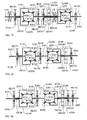
FIG. 1 is a schematic view showing the main structural components and system configuration according to the present invention. -
FIG 2 is a schematic view showing the operation state wherein the rotary kinetic energy is inputted from the first rotary kinetic energy source (A) for driving the carrier (C). -
FIG 3 is a schematic view showing the operation state wherein the rotary kinetic energy is inputted from the second rotary kinetic energy source (B) for driving the carrier (C). -
FIG 4 is a schematic view showing the operation state wherein the rotary kinetic energy is inputted from the first rotary kinetic energy source (A) for driving the second rotary kinetic energy source (B) and the carrier (C). -
FIG 5 is a schematic view showing the operation state wherein the rotary kinetic energy is inputted from both the first rotary kinetic energy source (A) and the second rotary kinetic energy source (B) for driving the carrier (C) together. -
FIG 6 is a schematic view showing the operation state wherein the rotary kinetic energy is inputted from the second rotary kinetic energy source (B) for driving the first rotary kinetic energy source (A) and the carrier (C). -
FIG 7 is a schematic view showing the operation state wherein the rotary kinetic energy is reversely inputted from the carrier (C) for driving the second rotary kinetic energy source (B). -
FIG. 8 is a schematic view showing the operation state wherein the rotary kinetic energy is reversely transmitted from the carrier (C) for driving the first rotary kinetic energy source (A) and the second rotary kinetic energy source (B). -
FIG 9 is a schematic view showing the operation state wherein the rotary kinetic energy is reversely transmitted from the carrier (C) for driving the first rotary kinetic energy source (A). -
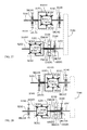
FIG. 10 is a schematic view showing the operation state wherein the rotating shaft (S202) at the output end of the second epicycle gear set (EG201) is further installed with a controllable brake device (BK104), and the first rotary kinetic energy source (A) is driven by the rotary kinetic energy of the second rotary kinetic energy source (B), according to the present invention. -
FIG. 11 is a schematic view showing that the transmission wheel (W200), the transmission wheel (W100), the rocker arm sleeve (AS201), the rocker arm (A201) and the controllable brake device (BK103) are installed at the output end of the second epicycle gear set (EG201), according to the present invention. -
FIG. 12 is a schematic view showing the operation state wherein the rotating shaft (S202) at the output end of the second epicycle gear set (EG201) as shown inFIG 11 is further installed with a controllable brake device (BK104), and the first rotary kinetic energy source (A) is driven by the rotary kinetic energy of the second rotary kinetic energy source (B). -
FIG 13 is a schematic view showing that the first epicycle gear set (EG101) and the second epicycle gear set (EG201) are arranged in parallel, and the transmission device (T100) is installed between the rotating shaft (S102) and the rotating shaft (S201). -
FIG 14 is a schematic view showing the operation state wherein the rotating shaft (S202) at the output end of the second epicycle gear set (EG201) as shown inFIG 13 is further installed with a controllable brake device (BK104), and the first rotary kinetic energy source (a) is driven by the rotary kinetic energy of the second rotary kinetic energy source (B). -
FIG 15 is a schematic structural view showing the rotary part of electric machine (EM102) of the electric machine (EM100) directly driving the rocker arm sleeve (AS201), according to the present invention. -
FIG 16 is a schematic view showing the operation state wherein the rotary kinetic energy is inputted from the first rotary kinetic energy source (A) for driving the carrier (C), according to the present invention. -
FIG 17 is a schematic view showing the operation state wherein the rotary kinetic energy is generated by the rotary part of electric machine (EM 102) of the electric machine (EM100) serving as the second rotary kinetic energy source (B) for driving the carrier (C), according to the present invention. -
FIG 18 is a schematic view showing the operation state wherein the rotary kinetic energy is inputted by the first rotary kinetic energy source (A) for driving the rotary part of electric machine (EM102) of the electric machine (EM100) and the carrier (C), according to the present invention. -
FIG. 19 is a schematic view showing the operation state wherein the rotary kinetic energy is jointly inputted from the first rotary kinetic energy source (A) and the rotary part of electric machine (EM102) of the electric machine (EM100) for driving the carrier (C), according to the present invention. -
FIG 20 is a schematic view showing the operation state wherein the rotary kinetic energy generated by the rotary part of electric machine (EM102) of the electric machine (EM100) serving as the second rotary kinetic energy source (B) drives the first rotary kinetic energy source (A) and the carrier (C), according to the present invention. -
FIG 21 is a schematic view showing the operation state wherein the rotary kinetic energy is reversely inputted from the carrier (C) for driving the rotary part of electric machine (EM102) of the electric machine (EM100), according to the present invention. -
FIG. 22 is a schematic view showing the operation state wherein the rotary kinetic energy is reversely inputted from the carrier (C) for driving the first rotary kinetic energy source (A) and the rotary part of electric machine (EM102) of the electric machine (EM100), according to the present invention. -
FIG 23 is a schematic view showing the operation state wherein the rotary kinetic energy is reversely inputted from the carrier (C) for driving the first rotary kinetic energy source (A), according to the present invention. -
FIG. 24 is a schematic view showing the operation state wherein the rotation shaft (S202) at the output end of the second epicycle gear set (EG201) is further installed with a controllable brake device (BK104), and the rotary kinetic energy generated by the rotary part of electric machine (EM102) of the electric machine (EM100) serving as the second rotary kinetic energy source (B) drives the first rotary kinetic energy source (A), according to the present invention. -
FIG 25 is a schematic view showing that the rotary part of electric machine (EM102) of the electric machine (EM100) and the rocker arm sleeve (AS201), the rocker arm (A201) and the controllable brake device (BK103) are installed at the output end of the second epicycle gear set (EG201), according to the present invention. -
FIG 26 is a schematic view showing the operation state wherein the rotation shaft (S202) at the output end of the second epicycle gear set (EG201) shown inFIG. 25 is further installed with a controllable brake device (BK104), and the rotary kinetic energy generated by the rotary part of electric machine (EM102) of the electric machine (EM100) serving as the second rotary kinetic energy source (B) drives the first rotary kinetic energy source (A), according to the present invention. -
FIG 27 is a schematic view showing that the first epicycle gear set (EG101) and the second epicycle gear set (EG201) are installed in parallel, and the transmission device (T100) is installed between the rotation shaft (S102) and the rotation shaft (S201), according to the present invention. -
FIG 28 is a schematic view showing the operation state wherein the rotation shaft (S202) at the output end of the second epicycle gear set (EG201) shown inFIG 27 is further installed with a controllable brake device (BK104), and the rotary kinetic energy serving as the second rotary kinetic energy source (B) drives the first rotary kinetic energy source (A), according to the present invention. -
- (A) : First rotary kinetic energy source
- (B) : Second rotary kinetic energy source
- (C) : Carrier
- (A101) · (A201) : Rocker arm
- (AS101) · (AS20 1) : Rocker arm sleeve
- (BK101) (BK102) · (BK103) (BK104) : Controllable brake device
- (EG101) : First epicycle gear set
- (EG201) : Second epicycle gear set
- (EM 100) : Electric machine
- (EM101) : Static part of electric machine
- (EM102) : Rotary part of electric machine
- (H100) : Housing
- (S100) · (S101) · (S102) · (S201) · (S202) : Rotating shaft
- (T100) · (T200) : Transmission device
- (W100) (W101) · (W102) · (W200) · (W201) · (W202) : Transmission wheel
- (W103) (W203) : Epicycle wheel
- The present invention provides a dual power driving system with epicycle gear sets transmitted in series, in which the input shaft, the output shaft and the controllable brake device of each epicycle gear set can be coaxially connected in series, or connected in parallel or not in parallel; the rotating shaft at the output end and the rotating shaft at the input end of each epicycle gear set can be directly connected, or an intermediate transmission device can be installed for connection, and through operating the controllable brake devices, the selections for the structural configurations of the dual power driving system are more variously than that of the conventional clutch devices driven by electromagnetic, pneumatic, oil pressure, or mechanics.
- The present invention provides a dual power driving system with epicycle gear sets transmitted in series, in which the input end of a first epicycle gear set is connected to a first rotary kinetic energy source, and the output end of the first epicycle gear set and the input end of a second epicycle gear set are connected for transmission, and a rocker arm of epicycle wheel of the second epicycle gear set is connected to a second rotary kinetic energy source through a transmission device, and the output end of the second epicycle gear set is served to drive a carrier; through installing a controllable brake device between the input end of the first epicycle gear set and a housing, and installing a controllable brake device between the output end of the first epicycle gear set and the housing, and installing a controllable brake device between the second rotary kinetic energy source and the rocker arm driven by the epicycle wheel of the second epicycle gear set as well as between any rotary unit of the transmission device and the housing, the operation modes of the dual power driving system can be controlled through operating and controlling the controllable brake devices.
- For the dual power driving system with epicycle gear sets transmitted in series of the present invention, in which the device served to generate rotary kinetic energy through input is structured by the internal combustion engine, the external combustion engine, the turbine engine, the Stirling engine, the power generator, the machinery having electromotive or power generation functions, the wind turbine, the liquid flow turbine or the manually driven device; and the first rotary kinetic energy source (A) and the second rotary kinetic energy source (B) are constituted by one or more than one of the above mentioned machineries for driving the carrier (C), which includes a vehicle, a boat, or a fly carrier or agricultural machinery, or an engineer or industry machinery or an energy equipment;
- The main components and operation theories of the dual power driving system with epicycle gear sets transmitted in series according to the present invention are disclosed as follows.
- Referring to
FIG. 1 , which is a schematic view showing the main structural components and system configuration according to the present invention; - As shown in
FIG 1 , it mainly consists of: - --First epicycle gear set (EG101): a transmission wheel (W101) at the input end, an epicycle wheel (W103), a transmission wheel (W102) at the output end are served to constitute the first epicycle gear set (EG101), wherein the mentioned wheels are gears or friction wheels; a rotating shaft (S101) is installed at the input end, one end of the rotating shaft (S101) is driven by the first rotary kinetic energy source (A), the other end thereof is connected to the transmission wheel (W101) at the input end, and a rotating shaft (S102) is installed at the output end for connecting to the transmission wheel (W102) at the output end, and one or more than one of epicycle wheels (W103) are installed between the transmission wheel (W101) and the transmission wheel (W102), the epicycle wheel (W103) is equipped with a rocker arm (A101) and a rocker arm sleeve (AS101), the rocker arm sleeve (AS101) is served to shaft-installed on both or at least one of the rotating shafts (S101, S102) and capable of performing relative rotation; a controllable brake device (BK101) is installed between the rocker arm (A101) and the rocker arm sleeve (AS101) and a housing (H100);
- --Second epicycle gear set (EG201): a transmission wheel (W201) at the input end, an epicycle wheel (W203), a transmission wheel (W202) at the output end are served to constitute the second epicycle gear set (EG201), wherein the mentioned wheels are gears or friction wheels; a. rotating shaft (S201) is installed at the input end, one end of the rotating shaft (S201) is connected to the rotating shaft (S102) at the output end of the first epicycle gear set (EG101) for transmission, the other end thereof is connected to the transmission wheel (W201) at the input end, and a rotating shaft (S202) is installed at the output end, one end of the rotating shaft (S202) is connected to the transmission wheel (W202) at the output end, the other end thereof is connected to a carrier (C), one or more than one of epicycle wheels (W203) are installed between the transmission wheel (W201) and the transmission wheel (W202), the epicycle wheel (W203) is equipped with a rocker arm (A201) and a rocker arm sleeve (AS20 1), the rocker arm sleeve (AS201) is shaft-installed on both or at least one of the rotating shafts (S201, S202) and capable of performing relative rotation; a controllable brake device (BK103) is installed between the rocker arm (A201) and the rocker arm sleeve (AS201) and the housing (H100), and a controllable brake device (BK102) is installed between the rotating shaft (S201) and the housing (H100);
- --Controllable brake device (BK101), (BK102), (BK103): constituted by a brake device driven through manual force, mechanical force, pneumatic force, hydraulic force or electromagnetic effect, for being controlled to perform operations of engagement braking or releasing, and the operation means can be engagement braking in a normal state and be releasing in an input control state, or can be releasing in the normal state and be engagement braking in the input control state;
- --Transmission device (T200): constituted by the transmission device including automatic transmission, manumatic transmission, semi-automatic transmission, or manual transmission with fixed speed ratio or variable speed ratio, which is structured by the transmission wheel train, or planetary transmission wheel train, or the epicycle wheel train, or the CVT, or the liquid force transmission device, which is composed of gears, friction wheels, belts and pulleys, chains and chain wheels;
- --Housing (H100): constituted by a static housing for accommodating the first epicycle gear set (EG 101), the second epicycle gear set (EG201), the controllable brake device (BK101), the controllable brake device (BK102) and the controllable brake device (BK103), and is connected to the first rotary kinetic energy source (A), the second rotary kinetic energy source (B) and the carrier (C);
- --The rotating shaft (S 101) at the input end of the first epicycle gear set (EG 101) is connected to the first rotary kinetic energy source (A);
- --The rotating shaft (S202) at the output end of the second epicycle gear set (EG201) is connected to the carrier (C);
- --The transmission wheel (W200) of the transmission device (T200) is connected to the rocker arm (A201) and the rocker arm sleeve (AS201) of the second epicycle gear set (EG201), and is served to connect with the second rotary kinetic energy source (B) via the transmission wheel (W100) and the rotating shaft (S100) which are transmitted for transmission;
- --The epicycle wheel (W103) of the first epicycle gear set (EG101) is shaft-installed to both or at least one of the rotating shafts (S101), (S102) through the rocker arm (A 101) and the rocker arm sleeve (AS101), and capable of rotating along the rotating shaft;
- --The controllable brake device (BK101) is installed between the rocker arm sleeve (AS101) and the rocker arm (A101) of the first epicycle gear set (FG101) and the housing (H100);
- --The rotating shaft (S102) at the output end of the first epicycle gear set (EG101) and the rotating shaft (S201) at the input end of the second epicycle gear set (EG201) are connected for transmission;
- --The controllable brake device (BK102) is installed between the rotating shaft (S201) and the housing (H 100);
- --The epicycle wheel (W203) of the second epicycle gear set (EG201) is sleeved to both or at least one of the rotating shafts (S201), (S202) through the rocker arm (A201) and the rocker arm sleeve (AS201), and capable of rotating along the rotating shaft;
- --The controllable brake device (BK103) is installed between the rocker arm sleeve (AS201) and the rocker arm (A201) of the second epicycle gear set (EG201) and the housing (H100); the rocker arm sleeve (AS201) and the rocker arm (A201) are connected to the transmission wheel (W200) of the transmission device (T200);
- According to the present invention, the operation functions of the dual power driving system with epicycle gear sets transmitted in series has one or more than one of the followings:
- (1) The controllable brake devices (BK101), (BK103) are in the engagement braking state; the first rotary kinetic energy source (A) inputs the rotary kinetic energy for driving the rotating shaft (S101), and then the rotary kinetic energy is transmitted through the rotating shaft (S102) at the output end of the first epicycle gear set (EG101) and the connected rotating shaft (S201) at the input end of the second epicycle gear set (EG201), and further through the rotating shaft (S202) at the output end of the second epicycle gear set (EG201) so as to drive the carrier (C);
FIG. 2 is a schematic view showing the operation state wherein the rotary kinetic energy is inputted from the first rotary kinetic energy source (A) for driving the carrier (C); - (2) The controllable brake device (BK102) is in the engagement braking state; the second rotary kinetic energy source (B) inputs the rotary kinetic energy for driving the rotating shaft (S100) and the transmission wheel (W100) of the transmission device (T200), and then the rotary kinetic energy is transmitted through the transmission wheel (W200) of the transmission device (T200) and the rocker arm sleeve (AS201) and the rocker arm (A201) to allow the epicycle wheel (W203) to epicycle on the transmission wheel (W201), and meanwhile to drive the transmission wheel (W202) and the rotating shaft (S202) at the output end so as to drive the carrier (C);
FIG. 3 is a schematic view showing the operation state wherein the rotary kinetic energy is inputted from the second rotary kinetic energy source (B) for driving the carrier (C); - (3) The controllable brake device (BK101) is in the engagement braking state; the first rotary kinetic energy source (A) inputs the rotary kinetic energy for driving the rotating shaft (S101), and then the rotary kinetic energy is transmitted through the rotating shaft (S102) at the output end of the first epicycle gear set (EG101) and the connected rotating shaft (S201) at the input end of the second epicycle gear set (EG201), and further through the rotating shaft (S202) at the output end of the second epicycle gear set (EG201) to drive the carrier (C), and meanwhile through the epicycle wheel (W203) of the second epicycle gear set (EG201) and the rocker arm (A201) and the rocker arm sleeve (AS201) and the transmission wheel (W200) of the transmission device (T200) to drive the transmission wheel (W100) and the rotating shaft (S100) so as to drive the second rotary kinetic energy source (B);
FIG. 4 is a schematic view showing the operation state wherein the rotary kinetic energy is inputted from the first rotary kinetic energy source (A) for driving the second rotary kinetic energy source (B) and the carrier (C); - (4) The controllable brake device (BK101) is in the engagement braking state; the first rotary kinetic energy source (A) inputs the rotary kinetic energy for driving the rotating shaft (S101), and then the rotary kinetic energy is transmitted through the rotating shaft (S102) at the output end of the first epicycle gear set (EG101) and the connected rotating shaft (S201) at the input end of the second epicycle gear set (EG201), and further through the rotating shaft (S202) at the output end of the second epicycle gear set (EG201) to drive the carrier (C), and meanwhile the second rotary kinetic energy source (B) inputs the rotary kinetic energy for driving the rotating shaft (S100), and then the rotary kinetic energy is transmitted through the transmission wheel (W100) and the transmission wheel (W200) of the transmission device (T200) and the rocker arm sleeve (AS201) and the rocker arm (A201) to allow the epicycle wheel (W203) to epicycle on the transmission wheel (W201), and meanwhile to drive the transmission wheel (W202) and the rotating shaft (S202), and thereby to drive the carrier (C) together with the rotary kinetic energy of the first rotary kinetic energy source (A);
FIG 5 is a schematic view showing the operation state wherein the rotary kinetic energy is inputted from both the first rotary kinetic energy source (A) and the second rotary kinetic energy source (B) for driving the carrier (C) together; - (5) The controllable brake device (BK101) is in the engagement braking state; the second rotary kinetic energy source (B) inputs the rotary kinetic energy for driving the rotating shaft (S100), and then the rotary kinetic energy transmits through the transmission wheel (W100) of the transmission device (T200) to drive the transmission wheel (W200) and the rocker arm sleeve (AS201) and the rocker arm (A201) so that the epicycle wheel (W203) is linked to drive the transmission wheel (W202), and thereby through the transmission wheel (W202) to drive the carrier (C), and meanwhile the epicycle wheel (W203) drives the transmission wheel (W201), and through the rotating shaft (S201) and the rotating shaft (S102) and through the transmission wheel (W102) and the epicycle wheel (W103) of the first epicycle gear set (EG101) to drive the transmission wheel (W101) and the rotating shaft (S101), and thereby further to drive the first rotary kinetic energy source (A);
FIG. 6 is a schematic view showing the operation state wherein the rotary kinetic energy is inputted from the second rotary kinetic energy source (B) for driving the first rotary kinetic energy source (A) and the carrier (C); - (6) The controllable brake device. (BK102) is in the engagement braking state; the carrier (C) reversely inputs the rotary kinetic energy for driving the transmission wheel (W202) of the second epicycle gear set (EG201) through the rotating shaft (S202), so as to drive the epicycle wheel (W203) and the rocker arm (A201) and the rocker arm sleeve (AS201) and the transmission wheel (W200) of the transmission device (T200), and the transmission wheel (W200) of the transmission device (T200) drives the transmission wheel (W100) and then drives the rotating shaft (S100) thereby to drive the second rotary kinetic energy source (B);
FIG 7 is a schematic view showing the operation state wherein the rotary kinetic energy is reversely inputted from the carrier (C) for driving the second rotary kinetic energy source (B); - (7) The controllable brake device (BK101) is in the engagement braking state; the carrier (C) reversely inputs the rotary kinetic energy for driving the transmission wheel (W202) of the second epicycle gear set (EG201) through the rotating shaft (S202), so as to drive the epicycle wheel (W203) and the rocker arm (A201) and the rocker arm sleeve (AS201) and the transmission wheel (W200) of the transmission device (T200), and the transmission wheel (W200) drives the transmission wheel (W100) and the rotating shaft (S100) so as to drive the second rotary kinetic energy source (B); meanwhile the epicycle wheel (W203) drives the transmission wheel (W201) so as to drive the rotating shaft (S201) and the rotating shaft (S102), thereby through the transmission wheel (W102), the epicycle wheel (W103), the transmission wheel (W101) of the first epicycle gear set (EG101) to drive the rotating shaft (S101), and further to drive the first rotary kinetic energy source (A) at the same time;
FIG. 8 is a schematic view showing the operation state wherein the rotary kinetic energy is reversely transmitted from the carrier (C) for driving the first rotary kinetic energy source (A) and the second rotary kinetic energy source (B); - (8) The controllable brake devices (BK101), (BK103) are in the engagement braking state; the carrier (C) reversely inputs the rotary kinetic energy for driving the transmission wheel (W202) of the second epicycle gear set (EG201) through the rotating shaft (S202), and then the rotary kinetic energy is transmitted through the epicycle wheel (W203) to drive the transmission wheel (W201), so as to drive the rotating shaft (S201) and the rotating shaft (S102), and further through the transmission wheel (W102) and the epicycle wheel (W103) of the first epicycle gear set (EG101) to drive the transmission wheel (W101), so as to drive the rotating shaft (S101) to further drive the first rotary kinetic energy source (A);
FIG 9 is a schematic view showing the operation state wherein the rotary kinetic energy is reversely transmitted from the carrier (C) for driving the first rotary kinetic energy source (A); - According to the present invention of the dual power driving system with epicycle gear sets transmitted in series,
FIG. 10 is a schematic view showing the operation state wherein the rotating shaft (S202) at the output end of the second epicycle gear set (EG201) is further installed with a controllable brake device (BK104), and the first rotary kinetic energy source (A) is driven by the rotary kinetic energy of the second rotary kinetic energy source (B), according to the present invention, in which a controllable brake device (BK104) is further installed between the rotating shaft (S202) at the output end of the second epicycle gear set (EG201) and the housing (H100) for fastening the rotating shaft (S202), and thereby the rotary kinetic energy is inputted from the second rotary kinetic energy source (B) to drive the rotating shaft (S100), and then transmitted through the transmission wheel (W100) of the transmission device (T200) to drive the transmission wheel (W200) and the rocker arm sleeve (AS201), and to rotationally drive the rocker arm (A201), so as to link the epicycle wheel (W203) to drive the transmission wheel (W201), and then transmitted through the rotating shaft (S201) and the rotating shaft (S102) and the transmission wheel (W 102) and the epicycle wheel (W103) of the first epicycle gear set (EG101) to drive the transmission wheel (W101) and the rotating shaft (S101), and thereby to drive the first rotary kinetic energy source (A) at the same time;FIG. 10 is a schematic view showing the operation state wherein the rotating shaft (202) at the output end of the second epicycle gear set (EG201) is further installed with a controllable brake device (BK104), and the first rotary kinetic energy source (A) is driven by the rotary kinetic energy of the second rotary kinetic energy source (B), according to the present invention; - According to the dual power driving system with epicycle gear sets transmitted in series of the present invention,
FIG. 11 is a schematic view showing that the transmission wheel (W200), the transmission wheel (W100), the rocker arm sleeve (AS201), the rocker arm (A201) and the controllable brake device (BK103) are installed at the output end of the second epicycle gear set (EG201), according to the present invention, in which the rocker arm (A201) and the rocker arm sleeve (AS201) of the second epicycle gear set (EG201) and the transmission wheel (W200) of the transmission device (T200) can be installed on the rotating shaft (S202) at the output end of the second epicycle gear set (EG201); - The dual power driving system with epicycle gear sets transmitted in series as shown in
FIG. 11 is further shown asFIG. 12 , which is a schematic view showing the operation state wherein the rotating shaft (S202) at the output end of the second epicycle gear set (EG201) as shown inFIG. 11 is further installed with a controllable brake device (BK104), and the first rotary kinetic energy source (A) is driven by the rotary kinetic energy of the second rotary kinetic energy source (B); wherein the rotating shaft (S202) at the output end of the second epicycle gear set (EG201) for installing the rocker arm (A201) and the rocker arm sleeve (AS201) of the second epicycle gear set (EG201) and the transmission wheel (W200) of the transmission device (T200) can be further installed with a controllable brake device (BK104); the structure is that the controllable brake device (BK104) is installed between the rotating shaft (S202) at the output end of the second epicycle gear set (EG201) and the housing (H100) for fastening the rotating shaft (S202), and thereby the rotary kinetic energy is inputted from the second rotary kinetic energy source (B) to drive the rotating shaft (S100), and then transmitted through the transmission wheel (W100) of the transmission device (T200) to drive the transmission wheel (W200) and the rocker arm sleeve (AS201), and to rotationally drive the rocker arm (A201), so as to link the epicycle wheel (W203) to drive the transmission wheel (W201), and then transmitted through the rotating shaft (S201) and the rotating shaft (S102) and the transmission wheel (W102) and the epicycle wheel (W103) of the first epicycle gear set (EG101) to drive the transmission wheel (W101) and the rotating shaft (S101), and thereby to drive the first rotary kinetic energy source (A) at the same time; - According to the present invention of the dual power driving system with epicycle gear sets transmitted in series,
FIG. 13 is a schematic view showing that the first epicycle gear set (EG101) and the second epicycle gear set (EG201) are arranged in parallel, and the transmission device (T100) is installed between the rotating shaft (S102) and the rotating shaft (S201), in which the first epicycle gear set (EG101) and the second epicycle gear set (EG201) can further be arranged in parallel and the transmission device (T100) is provided for series transmission, wherein the rotating shaft (S101) at the input end of the first epicycle gear set (EG101) is driven by the first rotary kinetic energy source (A), and the controllable brake device (BK101) is installed between the rotating shaft (S101) and the housing (H100); - The transmission device (T100) is installed between the rotating shaft (S102) and the rotating shaft (S201) at the input end of the second epicycle gear set (EG201), the controllable brake device (BK103) is installed between the rocker arm sleeve (AS201) and the housing (H100), and the rotating shaft (S202) at the output end of the second epicycle gear set (EG201) is served to drive the carrier (C);
- Transmission device (T100) is constituted by the transmission device including automatic transmission, manumatic transmission, semi-automatic transmission, or manual transmission with fixed speed ratio or variable speed ratio, which is structured by the transmission wheel train, or planetary transmission wheel train, or the epicycle wheel train, or the CVT, or the liquid force transmission device, which is composed of gears, friction wheels, belts and pulleys, chains and chain wheels;
- The epicycle wheel (W203) of the second epicycle gear set (EG201) is connected to the rocker arm (A201) and the rocker arm sleeve (AS201) and the transmission wheel (W200) of the transmission device (T200), and is linked to mutually transmit with the transmission wheel (W100), and thereby to connected with the second rotary kinetic energy source (B) through the rotating shaft (S 100);
- The controllable brake device (BK102) is installed between the rotating shaft (S102) at the output end of the first epicycle gear set (EG101) and the housing (H100), and the controllable brake device (BK102) can also be installed on the rotating shaft (S201) at the input end of the second epicycle gear set (EG201), the mentioned two installations provide the same function to the system;
- According to the embodiment of
FIG 13, FIG. 14 is a schematic view showing the operation state wherein the rotating shaft (S202) at the output end of the second epicycle gear set (EG201) as shown inFIG 13 is further installed with a controllable brake device (BK104), and the first rotary kinetic energy source (A) is driven by the rotary kinetic energy of the second rotary kinetic energy source (B), in which the controllable brake device (BK104) can be further installed on the rotating shaft (S202) at the output end of the second epicycle gear set (EG201), so as the kinetic energy of the first rotary kinetic energy source (A) can be driven by the second rotary kinetic energy source (B); the structure is that the controllable brake device (BK104) is installed between the rotating shaft (S202) at the output end of the second epicycle gear set (EG201) and the housing (H100) for fastening the rotating shaft (S202), and the rotary kinetic energy is inputted from the second rotary kinetic energy source (B) to drive the rotating shaft (S100), and then transmitted through the transmission wheel (W100) of the transmission device (T200) to drive the transmission wheel (W200) and the rocker arm sleeve (AS201), and to rotationally drive the rocker arm (A201), so as to link the epicycle wheel (W203) to drive the transmission wheel (W201), and then transmitted through the rotating shaft (S201) and the transmission device (T100) and the rotating shaft (S102) and further through the transmission wheel (W102) and the epicycle wheel (W103) of the first epicycle gear set (EG101) to drive the transmission wheel (W101) and the rotating shaft (S101) and thereby to drive the first rotary kinetic energy source (A) at the same time; - According to the present invention of the dual power driving system with epicycle gear sets transmitted in series, the controllable brake device (BK103) is served to control the transmission chain between the second rotary kinetic energy source (B) through the rotating shaft (S100), the transmission device (T200) and the rocker arm (A201) and the epicycle wheel (W203) of the second epicycle gear set (EG201) to be braked or capable of performing rotational driving, so the installation location of the controllable brake device (BK103) can be between the rotary part of the second rotary kinetic energy source (B) and the housing (H100), or between the rotating shaft (S100), the transmission device (T200), the rocker arm (A201) of the rotating component in the mentioned transmission chain and the housing (H100).
- According to the present invention of the dual power driving system with epicycle gear sets transmitted in series, the first rotary kinetic energy source (A), the second rotary kinetic energy source (B), the carrier (C), the first epicycle gear set (EG 101), the second epicycle gear set (EG201) and each controllable brake device set are installed in the housing (H100) which can be integrally formed as one unit or assembled by plural units, or are installed in two or more or than two of independent housings.
- According to the present invention of the dual power driving system with epicycle gear sets transmitted in series, the rotary part of electric machine (EM102) of the electric machine (EM100) can directly drive the rocker arm sleeve (AS201), so the transmission wheel (W200), the transmission wheel (W100) and the rotation shaft (S100) are not provided for reducing the occupied space;
-
FIG 15 is a schematic structural view showing the rotary part of electric machine (EM 102) of the electric machine (EM100) directly driving the rocker arm sleeve (AS201), according to the present invention; - As shown in
FIG 15 , it mainly consists of: - --First epicycle gear set (EG101): a transmission wheel (W101) at the input end, an epicycle wheel (W103), a transmission wheel (W102) at the output end are served to constitute the first epicycle gear set (EG101), wherein the mentioned wheels are gears or friction wheels; a rotating shaft (S 101) is installed at the input end, one end of the rotating shaft (S 101) is driven by the first rotary kinetic energy source (A), the other end thereof is connected to the transmission wheel (W101) at the input end, and a rotating shaft (S102) is installed at the output end for connecting to the transmission wheel (W102) at the output end, and one or more than one of epicycle wheels (W103) are installed between the transmission wheel (W101) and the transmission wheel (W102), the epicycle wheel (W103) is equipped with a rocker arm (A 101) and a rocker arm sleeve (AS 101), the rocker arm sleeve (AS101) is served to shaft-installed on both or at least one of the rotating shafts (S101, S102) and capable of performing relative rotation; a controllable brake device (BK101) is installed between the rocker arm (A101) and the rocker arm sleeve (AS101) and a housing (H100);
- --Second epicycle gear set (EG201): a transmission wheel (W201) at the input end, an epicycle wheel (W203), a transmission wheel (W202) at the output end are served to constitute the second epicycle gear set (EG201), wherein the mentioned wheels are gears or friction wheels; a rotating shaft (S201) is installed at the input end, one end of the rotating shaft (S201) is connected to the rotating shaft (S102) at the output end of the first epicycle gear set (EG101) for transmission, the other end thereof is connected to the transmission wheel (W201) at the input end, and a rotating shaft (S202) is installed at the output end, one end of the rotating shaft (S202) is connected to the transmission wheel (W202) at the output end, the other end thereof is connected to a carrier (C), one or more than one of epicycle wheels (W203) are installed between the transmission wheel (W201) and the transmission wheel (W202), the epicycle wheel (W203) is equipped with a rocker arm (A201) and a rocker arm sleeve (AS201), the rocker arm sleeve (AS201) is shaft-installed on both or at least one of the rotating shafts (S201, S202) and capable of performing relative rotation, the rocker arm sleeve (A.S201) is connected to the rotary part of electric machine (EM102) of the electric machine (EM100) serving as the second rotary kinetic energy source (B) for mutually driving; a controllable brake device (BK103) is installed between the rocker arm (A201) and the rocker arm sleeve (AS201) and the housing (H100), and a controllable brake device (BK102) is installed between the rotating shaft (S201) and the housing (H100);
- -- Controllable brake device (BK101), (BK102), (BK103): constituted by a brake device driven through manual force, mechanical force, pneumatic force, hydraulic force or electromagnetic effect, for being controlled to perform operations of engagement braking or releasing, and the operation means can be engagement braking in a normal state and be releasing in an input control state, or can be releasing in the normal state and be engagement braking in the input control state;
- -- Electric machine (EM100): constituted by a rotary electric machine, including DC or AC, synchronous or asynchronous, brush or brushless, coiled excitation or permanent magnet pole rotary electric machines, mainly served as motor operation function and also capable of being served as power generator function for reversely inputting the rotary kinetic energy to be served as the second rotary kinetic energy source (B);
- -- Housing (H100): constituted by a static housing for accommodating the first epicycle gear set (EG101), the second epicycle gear set (EG201), the controllable brake device (BK101), the controllable brake device (BK102) and the controllable brake device (BK103), and is connected to the first rotary kinetic energy source (A), the static part of electric machine (EM101) of the electric machine (EM100) serving as the second rotary kinetic energy source (B) and the carrier (C);
- -- The rotating shaft (S 101) at the input end of the first epicycle gear set (EG101) is connected to the first rotary kinetic energy source (A);
- -- The rotating shaft (S202) at the output end of the second epicycle gear set (EG201) is connected to the carrier (C);
- -- the rotary part of electric machine (EM102) of the electric machine (EM100) serving as the second rotary kinetic energy source (B) is connected to the rocker arm (A201) and the rocker arm sleeve (AS201) of the second epicycle gear set (EG201), the static part of electric machine (EM101) of the electric machine (EM100) is fastened and connected with the housing (H 100);
- -- The epicycle wheel (W103) of the first epicycle gear set (EG101) is shaft-installed to both or at least one of the rotating shafts (S101), (S102) through the rocker arm (A101) and the rocker arm sleeve (AS101), and capable of rotating along the rotating shaft;
- -- The controllable brake device (BK101) is installed between the rocker arm sleeve (AS101) and the rocker arm (A101) of the first epicycle gear set (EG101) and the housing (H100);
- -- The rotating shaft (S102) at the output end of the first epicycle gear set (EG101) and the rotating shaft (S201) at the input end of the second epicycle gear set (EG201) are connected for transmission;
- -- The controllable brake device (BK102) is installed between the rotating shaft (S201) and the housing (H 100);
- -- The epicycle wheel (W203) of the second epicycle gear set (EG201) is sleeved to both or at least one of the rotating shafts (S201), (S202) through the rocker arm (A201) and the rocker arm sleeve (AS201), and capable of rotating along the rotating shaft;
- -- The controllable brake device (BK103) is installed between the rocker arm sleeve (AS201) and the rocker arm (A201) of the second epicycle gear set (EG201) and the housing (H100); the rocker arm sleeve (AS201) and the rocker arm (A201) are connected to the rotary part of electric machine (EM 102) of the electric machine (EM 100);
- According to the present invention, the operation functions of the dual power driving system with epicycle gear sets transmitted in series has one or more than one of the followings:
- (1) The controllable brake devices (BK101), (BK103) are in the engagement braking state; the first rotary kinetic energy source (A) inputs the rotary kinetic energy for driving the rotating shaft (S101), and then the rotary kinetic energy is transmitted through the rotating shaft (S102) at the output end of the first epicycle gear set (EG101) and the connected rotating shaft (S201) at the input end of the second epicycle gear set (EG201), and further through the rotating shaft (S202) at the output end of the second epicycle gear set (EG201) so as to drive the carrier (C);
FIG. 16 is a schematic view showing the operation state wherein the rotary kinetic energy is inputted from the first rotary kinetic energy source (A) for driving the carrier (C); - (2) The controllable brake device (BK102) is in the engagement braking state; the electric machine (EM100) serving as the second rotary kinetic energy source (B) transmits electricity to the rotary part of electric machine (EM102) to generate the rotary kinetic energy for driving the rocker arm sleeve (AS201) and the rocker arm (A201) to allow the epicycle wheel (W203) to epicycle on the transmission wheel (W201), and meanwhile to drive the transmission wheel (W202) and the rotating shaft (S202) at the output end so as to drive the carrier (C);
FIG. 17 is a schematic view showing the operation state wherein the rotary kinetic energy is generated by the rotary part of electric machine (EM102) of the electric machine (EM100) serving as the second rotary kinetic energy source (B) for driving the carrier (C), according to the present invention; - (3) The controllable brake device (BK101) is in the engagement braking state; the first rotary kinetic energy source (A) inputs the rotary kinetic energy for driving the rotating shaft (S101), and then the rotary kinetic energy is transmitted through the rotating shaft (S102) at the output end of the first epicycle gear set (EG101) and the connected rotating shaft (S201) at the input end of the second epicycle gear set (EG201), and further through the rotating shaft (S202) at the output end of the second epicycle gear set (EG201) to drive the carrier (C), and meanwhile through the epicycle wheel (W203) of the second epicycle gear set (EG201) and the rocker arm (A201) and the rocker arm sleeve (AS201) for driving the rotary part of electric machine (EM102) of the electric machine (EM100);
FIG 18 is a schematic view showing the operation state wherein the rotary kinetic energy is inputted by the first rotary kinetic energy source (A) for driving the rotary part of electric machine (EM102) of the electric machine (EM 100) and the carrier (C), according to the present invention; - (4) The controllable brake device (BK101) is in the engagement braking state; the first rotary kinetic energy source (A) inputs the rotary kinetic energy for driving the rotating shaft (S101), and then the rotary kinetic energy is transmitted through the rotating shaft (S102) at the output end of the first epicycle gear set (EG101) and the connected rotating shaft (S201) at the input end of the second epicycle gear set (EG201), and further through the rotating shaft (S202) at the output end of the second epicycle gear set (EG201) to drive the carrier (C), and meanwhile the rotary part of electric machine (EM102) of the electric machine (EM100) serving as the second rotary kinetic energy source (B) inputs the rotary kinetic energy for driving the rocker arm sleeve (AS201) and the rocker arm (A201) to allow the epicycle wheel (W203) to epicycle on the transmission wheel (W201), so as to drive the transmission wheel (W202) and the rotating shaft (S202) at the same time, and thereby together with the rotary kinetic energy of the first rotary kinetic energy source (A) to drive the carrier (C);
FIG. 19 is a schematic view showing the operation state wherein the rotary kinetic energy is jointly inputted from the first rotary kinetic energy source (A) and the rotary part of electric machine (EM102) of the electric machine (EM100) for driving the carrier (C), according to the present invention; - (5) The controllable brake device (BK101) is in the engagement braking state; the rotary part of electric machine (EM102) of the electric machine (EM100) serving as the second rotary kinetic energy source (B) generates the rotary kinetic energy for driving the rocker arm sleeve (AS201) and the rocker arm (A201) so that the epicycle wheel (W203) is linked to drive the transmission wheel (W202), and thereby through the transmission wheel (W202) to drive the carrier (C), and meanwhile the epicycle wheel (W203) drives the transmission wheel (W201), and through the rotating shaft (S201) and the rotating shaft (S102) and through the transmission wheel (W102) and the epicycle wheel (W103) of the first epicycle gear set (EG 101) to drive the transmission wheel (W101) and the rotating shaft (S101), and thereby further to drive the first rotary kinetic energy source (A);
FIG 20 is a schematic view showing the operation state wherein the rotary kinetic energy generated by the rotary part of electric machine (EM102) of the electric machine (EM100) serving as the second rotary kinetic energy source (B) drives the first rotary kinetic energy source (A) and the carrier (C), according to the present invention; - (6) The controllable brake device (BK102) is in the engagement braking state; the carrier (C) reversely inputs the rotary kinetic energy for driving the transmission wheel (W202) of the second epicycle gear set (EG201) through the rotating shaft (S202), so as to drive the epicycle wheel (W203) and the rocker arm (A201) and the rocker arm sleeve (AS201) thereby to drive the rotary part of electric machine (EM102) of the electric machine (EM100);
FIG. 21 is a schematic view showing the operation state wherein the rotary kinetic energy is reversely inputted from the carrier (C) for driving the rotary part of electric machine (EM102) of the electric machine (EM100), according to the present invention; - (7) The controllable brake device (BK101) is in the engagement braking state; the carrier (C) reversely inputs the rotary kinetic energy for driving the transmission wheel (W202) of the second epicycle gear set (EG201) through the rotating shaft (S202), so as to drive the epicycle wheel (W203) and the rocker arm (A201) and the rocker arm sleeve (AS201) thereby to drive the rotary part of electric machine (EM102) of the electric machine (EM100); meanwhile the epicycle wheel (W203) drives the transmission wheel (W201) so as to drive the rotating shaft (S201) and the rotating shaft (S102), thereby through the transmission wheel (W102), the epicycle wheel (W103), the transmission wheel (W101) of the first epicycle gear set (EG101) to drive the rotating shaft (S101), and further to drive the first rotary kinetic energy source (A) at the same time;
FIG. 22 is a schematic view showing the operation state wherein the rotary kinetic energy is reversely inputted from the carrier (C) for driving the first rotary kinetic energy source (A) and the rotary part of electric machine (EM102) of the electric machine (EM 100), according to the present invention; - (8) The controllable brake devices (BK101), (BK103) are in the engagement braking state; the carrier (C) reversely inputs the rotary kinetic energy for driving the transmission wheel (W202) of the second epicycle gear set (EG201) through the rotating shaft (S202), and then the rotary kinetic energy is transmitted through the epicycle wheel (W203) to drive the transmission wheel (W201), so as to drive the rotating shaft (S201) and the rotating shaft (S102), and further through the transmission wheel (W102) and the epicycle wheel (W103) of the first epicycle gear set (EG101) to drive the transmission wheel (W101), so as to drive the rotating shaft (S101) to further drive the first rotary kinetic energy source (A);
FIG. 23 is a schematic view showing the operation state wherein the rotary kinetic energy is reversely inputted from the carrier (C) for driving the first rotary kinetic energy source (A); - According to the dual power driving system with epicycle gear sets transmitted in series shown in
FIG 15 ,FIG 24 is a schematic view showing the operation state wherein the rotating shaft (S202) at the output end of the second epicycle gear set (EG201) is further installed with a controllable brake device (BK104), and the rotary kinetic energy generated by the rotary part of electric machine (EM102) of the electric machine (EM100) serving as the second rotary kinetic energy source (B) drives the first rotary kinetic energy source (A), according to the present invention, in which a controllable brake device (BK104) is further installed between the rotating shaft (S202) at the output end of the second epicycle gear set (EG201) and the housing (H100) for fastening the rotating shaft (S202), so when the controllable brake device (BK103) is in the releasing state, the rotary part of electric machine (EM102) of the electric machine (EM100) serving as the second rotary kinetic energy source (B) inputs the rotary kinetic energy for driving the rocker arm sleeve (AS201) and the rocker arm (A201), so as to link the epicycle wheel (W203) to drive the transmission wheel (W201), and then the rotary kinetic energy is transmitted through the rotating shaft (S201) and the rotating shaft (S102) and the transmission wheel (W102) and the epicycle wheel (W103) of the first epicycle gear set (EG101) to drive the transmission wheel (W101) and the rotating shaft (S101), and thereby to drive the first rotary kinetic energy source (A) at the same time; - According to the dual power driving system with epicycle gear sets transmitted in series shown in
FIG 15 ,FIG 25 is a schematic view showing that the rotary part of electric machine (EM102) of the electric machine (EM100) and the rocker arm sleeve (AS201), the rocker arm (A201) and the controllable brake device (BK 103) are installed at the output end of the second epicycle gear set (EG201), according to the present invention, in which the rocker arm sleeve (AS201), the rocker arm (A201) of the second epicycle gear set (EG201), the controllable brake device (BK103) and the rotary part of electric machine (EM102) of the electric machine (EM100) are installed on the rotating shaft (S202) at the output end of the second epicycle gear set (EG201); - According to the dual power driving system with epicycle gear sets transmitted in series shown in
FIG. 25, FIG. 26 is a schematic view showing the operation state wherein the rotating shaft (S202) at the output end of the second epicycle gear set (EG201) shown inFIG 25 is further installed with a controllable brake device (BK104), and the rotary kinetic energy generated by the rotary part of electric machine (EM102) of the electric machine (EM100) serving as the second rotary kinetic energy source (B) drives the first rotary kinetic energy source (A), according to the present invention; a controllable brake device (BK104) is further installed between the rotating shaft (S202) at the output end of the second epicycle gear set (EG201) and the housing (H100), and through controlling the controllable brake device (BK103) installed between the rocker arm sleeve (AS201) and the housing (H100) to be released, the controllable brake device (BK104) can be controlled to perform engagement braking, so the rotary part of electric machine (EM102) of the electric machine (EM100) drives the rocker arm (A201) to link the epicycle wheel (W203) for driving the transmission wheel (W201), and through the rotating shaft (S201) and the rotating shaft (S102) and through the transmission wheel (W102) and the epicycle wheel (W103) of the first epicycle gear set (EG101), the transmission wheel (W101) and the rotating shaft (S101) are driven, thereby driving the first rotary kinetic energy source (A) at the same time; or through controlling the controllable brake device (BK103) being in the engagement braking state, the controllable brake device (BK104), the controllable brake device (BK102) and the controllable brake device (BK101) are released, and the rotating shaft (S101) mutually transmits with the rotating shaft (S201). - According to the dual power driving system with epicycle gear sets transmitted in series shown in
FIG 15 ,FIG. 27 is a schematic view showing that the first epicycle gear set (EG101) and the second epicycle gear set (EG201) are installed in parallel, and the transmission device (T100) is installed between the rotating shaft (S102) and the rotating shaft (S201), according to the present invention, in which the first epicycle gear set (EG101) and the second epicycle gear set (EG201) are arranged in parallel, and the transmission device (T100) is served to transmit in series, wherein the rotating shaft (S101) at the input end of the first epicycle gear set (EG101) is driven by the first rotary kinetic energy source (A), and the controllable brake device (BK101) is installed between the rotating shaft (S101) and the housing (H 100); - The transmission device (T100) is installed between the rotating shaft (S102) and the rotating shaft (S201) at the input end of the second epicycle gear set (EG201), the controllable brake device (BK103) is installed between the rocker arm sleeve (AS201) and the housing (H100), and the rotating shaft (S202) at the output end of the second epicycle gear set (EG201) is served to drive the carrier (C);
- Transmission device (T100) is constituted by the transmission device including automatic transmission, manumatic transmission, semi-automatic transmission, or manual transmission with fixed speed ratio or variable speed ratio, which is structured by the transmission wheel train, or planetary transmission wheel train, or the epicycle wheel train, or the CVT, or the liquid force transmission device, which is composed of gears, friction wheels, belts and pulleys, chains and chain wheels;
- The epicycle wheel (W203) of the second epicycle gear set (EG201) is connected to the rocker arm (A201) and the rocker arm sleeve (AS201) and the rotary part of electric machine (EM102) of the electric machine (EM100);
- The controllable brake device (BK102) is installed between the rotating shaft (S102) at the output end of the first epicycle gear set (EG101) and the housing (H100), and the controllable brake device (BK102) can also be installed on the rotating shaft (S201) at the input end of the second epicycle gear set (EG201);
- According to the dual power driving system with epicycle gear sets transmitted in series,
FIG 28 is a schematic view showing the operation state wherein the rotating shaft (S202) at the output end of the second epicycle gear set (EG201) shown inFIG 27 is further installed with a controllable brake device (BK104), and the rotary kinetic energy serving as the second rotary kinetic energy source (B) drives the first rotary kinetic energy source (A); the controllable brake device (BK104) is installed on the rotating shaft (S202) at the output end of the second epicycle gear set (EG201) for fastening the rotating shaft (S202), so when the controllable brake device (BK103) is in the releasing state, the rotary part of electric machine (EM102) of the electric machine (EM100) serving as the second rotary kinetic energy source (B) inputs the rotary kinetic energy for driving the rocker arm sleeve (AS201) and rotationally driving the rocker arm (A201), so as to link the epicycle wheel (W203) to drive the transmission wheel (W201), and then transmitted through the rotating shaft (S201) and the transmission device (T100) and the rotating shaft (S102) and further through the transmission wheel (W102) and the epicycle wheel (W103) of the first epicycle gear set (EG101) to drive the transmission wheel (W101) and the rotating shaft (S101) and thereby to drive the first rotary kinetic energy source (A) at the same time; or the rotating shaft (S101) inputs the rotary kinetic energy for driving the second rotary kinetic energy source (B) and the carrier (C); - In the dual power driving system with epicycle gear sets transmitted in series shown in
FIG. 15 , the controllable braked device (BK103) is used for controlling the rotary part of electric machine (EM102) of the electric machine (EM100) serving as the second rotary kinetic energy source (B) and controlling the transmission chain between and the rocker arm (A201) and the epicycle wheel (W203) of the second epicycle gear set (EG201) to perform engagement braking or rotational driving, wherein the installation location of the controllable brake device (BK103) is between the rotary end of the rotary part of electric machine (EM102) of the electric machine (EM100) and the housing (H100), or between the rotating shaft (S100), the transmission device (T200), the rocker arm (A201) of the rotary components of the mentioned transmission chain and the housing (H100). - When the dual power driving system with epicycle gear sets transmitted in series shown in
FIG. 15 is in practical application, the first rotary kinetic energy source (A), the electric machine (EM100) serving as the second rotary kinetic energy source (B), the carrier (C), the first epicycle gear set (EG101), the second epicycle gear set (EG201) and each set of controllable brake device can be installed in the housing (H100) integrally formed or assembled as one unit, or installed in two or more than two of individual housings. - In a first aspect, the present invention provides a dual power driving system, comprising:
- a first epicycle gear set (EG101) having: a first transmission wheel (W101) at an input end, a first epicycle wheel (W103), a second transmission wheel (W102) at an output end;
- a first rotating shaft (S101), wherein one end of the rotating shaft (S101) is arranged to be driven by a first rotary kinetic energy source (A), and the other end thereof is connected to the first transmission wheel (W101) at the input end;
- a second rotating shaft (S102), connected to the second transmission wheel (W102) at the output end;
- a first rocker arm (A101) and a first rocker arm sleeve (AS101), the first rocker arm coupled to the first epicycle wheel (W103) and the first rocker arm sleeve (AS101) is shaft-installed on at least one of the rotating shafts (S101, S102) and capable of performing relative rotation;
- a first controllable brake device (BK101) is installed between the first rocker arm (A101) and the first rocker arm sleeve (AS101) and a housing (H100);
- a second epicycle gear set (EG201) having: a third transmission wheel (W201) at the input end, a second epicycle wheel (W203), a fourth transmission wheel (W202) at the output end;
- a third rotating shaft (S201), wherein one end of the rotating shaft (S201) is coupled to the second rotating shaft (S102) and the other end thereof is connected to the third transmission wheel (W201) at the input end, and a fourth rotating shaft (S202) is connected to the fourth transmission wheel (W202) at the output end, the other end thereof is arranged to drive a carrier (C);
- a second rocker arm (A201 and a second rocker arm sleeve (AS201), the second rocker arm coupled to the second epicycle wheel (W203), and the second rocker arm sleeve (AS201) is shaft-installed on at least one of the rotating shafts (S201, S202) and capable of performing relative rotation;
- a second controllable brake device (BK103) is installed between the second rocker arm (A201) and the second rocker arm sleeve (AS201) and the housing (H100);
- a third controllable brake device (BK102) is installed between the third rotating shaft (S201) and the housing (H100).
- In a further aspect, the system further comprises a first transmission device (T200).
- In a further aspect, the transmission device (T200) includes a fifth transmission wheel (W200) which is coupled to the second rocker arm (A201) and the second rocker arm sleeve (AS201) of the second epicycle gear set (EG201); and a sixth transmission wheel (W100) which is coupled to a fourth rotating shaft (S100) which is arranged to be coupled to a second rotary kinetic energy source (B).
Claims (13)
- A dual power driving system with epicycle gear sets transmitted in series, in which the input end of a first epicycle gear set is connected to a first rotary kinetic energy source, and the output end of the first epicycle gear set and the input end of a second epicycle gear set are connected for transmission, and a rocker arm of epicycle wheel of the second epicycle gear set is connected to a second rotary kinetic energy source through a transmission device, and the output end of the second epicycle gear set is served to drive a carrier; through installing a controllable brake device between the input end of the first epicycle gear set and a housing, and installing a controllable brake device between the output end of the first epicycle gear set and the housing, and installing a controllable brake device between the second rotary kinetic energy source and the rocker arm driven by the epicycle wheel of the second epicycle gear set as well as between any rotary unit of the transmission device and the housing, the operation modes of the dual power driving system can be controlled through operating and controlling the controllable brake devices, wherein the device served to generate rotary kinetic energy through input is structured by the internal combustion engine, the external combustion engine, the turbine engine, the Stirling engine, the power generator, the machinery having electromotive or power generation functions, the wind turbine, the liquid flow turbine or the manually driven device; and the first rotary kinetic energy source (A) and the second rotary kinetic energy source (B) are constituted by one or more than one of the above mentioned machineries, wherein it mainly consists of:--First epicycle gear set (EG101): a transmission wheel (W101) at the input end, an epicycle wheel (W103), a transmission wheel (W102) at the output end are served to constitute the first epicycle gear set (EG101), wherein the mentioned wheels are gears or friction wheels; a rotating shaft (S101) is installed at the input end, one end of the rotating shaft (S101) is driven by the first rotary kinetic energy source (A), the other end thereof is connected to the transmission wheel (W101) at the input end, and a rotating shaft (S102) is installed at the output end for connecting to the transmission wheel (W102) at the output end, and one or more than one of epicycle wheels (W103) are installed between the transmission wheel (W101) and the transmission wheel (W102), the epicycle wheel (W103) is equipped with a rocker arm (A101) and a rocker arm sleeve (AS101), the rocker arm sleeve (AS101) is served to shaft-installed on both or at least one of the rotating shafts (S101, S102) and capable of performing relative rotation; a controllable brake device (BK101) is installed between the rocker arm (A101) and the rocker arm sleeve (AS101) and a housing (H100);--Second epicycle gear set (EG201): a transmission wheel (W201) at the input end, an epicycle wheel (W203), a transmission wheel (W202) at the output end are served to constitute the second epicycle gear set (EG201), wherein the mentioned wheels are gears or friction wheels; a rotating shaft (S201) is installed at the input end, one end of the rotating shaft (S201) is connected to the rotating shaft (S102) at the output end of the first epicycle gear set (EG101) for transmission, the other end thereof is connected to the transmission wheel (W201) at the input end, and a rotating shaft (S202) is installed at the output end, one end of the rotating shaft (S202) is connected to the transmission wheel (W202) at the output end, the other end thereof is connected to a carrier (C), one or more than one of epicycle wheels (W203) are installed between the transmission wheel (W201) and the transmission wheel (W202), the epicycle wheel (W203) is equipped with a rocker arm (A201) and a rocker arm sleeve (AS201), the rocker arm sleeve (AS201) is shaft-installed on both or at least one of the rotating shafts (S201, S202) and capable of performing relative rotation; a controllable brake device (BK103) is installed between the rocker arm (A201) and the rocker arm sleeve (AS201) and the housing (H100), and a controllable brake device (BK102) is installed between the rotating shaft (S201) and the housing (H 100);--Controllable brake device (BK101), (BK102), (BK103): constituted by a brake device driven through manual force, mechanical force, pneumatic force, hydraulic force or electromagnetic effect, for being controlled to perform operations of engagement braking or releasing, and the operation means can be engagement braking in a normal state and be releasing in an input control state, or can be releasing in the normal state and be engagement braking in the input control state;--Transmission device (T200): constituted by the transmission device including automatic transmission, manumatic transmission, semi-automatic transmission, or manual transmission with fixed speed ratio or variable speed ratio, which is structured by the transmission wheel train, or planetary transmission wheel train, or the epicycle wheel train, or the CVT, or the liquid force transmission device, which is composed of gears, friction wheels, belts and pulleys, chains and chain wheels;--Housing (H100): constituted by a static housing for accommodating the first epicycle gear set (EG101), the second epicycle gear set (EG201), the controllable brake device (BK101), the controllable brake device (BK102) and the controllable brake device (BK103), and is connected to the first rotary kinetic energy source (A), the second rotary kinetic energy source (B) and the carrier (C);--The rotating shaft (S101) at the input end of the first epicycle gear set (EG101) is connected to the first rotary kinetic energy source (A);--The rotating shaft (S202) at the output end of the second epicycle gear set (EG201) is connected to the carrier (C);--The transmission wheel (W200) of the transmission device (T200) is connected to the rocker arm (A201) and the rocker arm sleeve (AS201) of the second epicycle gear set (EG201), and is served to connect with the second rotary kinetic energy source (B) via the transmission wheel (W100) and the rotating shaft (S100) which are transmitted for transmission;--The epicycle wheel (W103) of the first epicycle gear set (EG101) is shaft-installed to both or at least one of the rotating shafts (S101), (S102) through the rocker arm (A101) and the rocker arm sleeve (AS101), and capable of rotating along the rotating shaft;--The controllable brake device (BK101) is installed between the rocker arm sleeve (AS101) and the rocker arm (A101) of the first epicycle gear set (FG101) and the housing (H100);--The rotating shaft (S102) at the output end of the first epicycle gear set (EG101) and the rotating shaft (S201) at the input end of the second epicycle gear set (EG201) are connected for transmission;--The controllable brake device (BK102) is installed between the rotating shaft (S201) and the housing (H100);--The epicycle wheel (W203) of the second epicycle gear set (EG201) is sleeved to both or at least one of the rotating shafts (S201), (S202) through the rocker arm (A201) and the rocker arm sleeve (AS201), and capable of rotating along the rotating shaft;--The controllable brake device (BK103) is installed between the rocker arm sleeve (AS201) and the rocker arm (A201) of the second epicycle gear set (EG201) and the housing (H100); the rocker arm sleeve (AS201) and the rocker arm (A201) are connected to the transmission wheel (W200) of the transmission device (T200), so the installation location of the controllable brake device (BK103) can be between the rotary part of the second rotary kinetic energy source (B) and the housing (H100), or between the rotating shaft (S100), the transmission device (T200), the rocker arm (A201) of the rotating component in the mentioned transmission chain and the housing (H100);
According to the present invention, the operation functions of the dual power driving system with epicycle gear sets transmitted in series has one or more than one of the followings:(1) The controllable brake devices (BK101), (BK103) are in the engagement braking state; the first rotary kinetic energy source (A) inputs the rotary kinetic energy for driving the rotating shaft (S101), and then the rotary kinetic energy is transmitted through the rotating shaft (S102) at the output end of the first epicycle gear set (EG101) and the connected rotating shaft (S201) at the input end of the second epicycle gear set (EG201), and further through the rotating shaft (S202) at the output end of the second epicycle gear set (EG201) so as to drive the carrier (C);(2) The controllable brake device (BK102) is in the engagement braking state; the second rotary kinetic energy source (B) inputs the rotary kinetic energy for driving the rotating shaft (S100) and the transmission wheel (W100) of the transmission device (T200), and then the rotary kinetic energy is transmitted through the transmission wheel (W200) of the transmission device (T200) and the rocker arm sleeve (AS201) and the rocker arm (A201) to allow the epicycle wheel (W203) to epicycle on the transmission wheel (W201), and meanwhile to drive the transmission wheel (W202) and the rotating shaft (S202) at the output end so as to drive the carrier (C);(3) The controllable brake device (BK101) is in the engagement braking state; the first rotary kinetic energy source (A) inputs the rotary kinetic energy for driving the rotating shaft (S101), and then the rotary kinetic energy is transmitted through the rotating shaft (S102) at the output end of the first epicycle gear set (EG101) and the connected rotating shaft (S201) at the input end of the second epicycle gear set (EG201), and further through the rotating shaft (S202) at the output end of the second epicycle gear set (EG201) to drive the carrier (C), and meanwhile through the epicycle wheel (W203) of the second epicycle gear set (EG201) and the rocker arm (A201) and the rocker arm sleeve (AS201) and the transmission wheel (W200) of the transmission device (T200) to drive the transmission wheel (W100) and the rotating shaft (S100) so as to drive the second rotary kinetic energy source (B);(4) The controllable brake device (BK101) is in the engagement braking state; the first rotary kinetic energy source (A) inputs the rotary kinetic energy for driving the rotating shaft (S101), and then the rotary kinetic energy is transmitted through the rotating shaft (S102) at the output end of the first epicycle gear set (EG101) and the connected rotating shaft (S201) at the input end of the second epicycle gear set (EG201), and further through the rotating shaft (S202) at the output end of the second epicycle gear set (EG201) to drive the carrier (C), and meanwhile the second rotary kinetic energy source (B) inputs the rotary kinetic energy for driving the rotating shaft (S100), and then the rotary kinetic energy is transmitted through the transmission wheel (W100) and the transmission wheel (W200) of the transmission device (T200) and the rocker arm sleeve (AS201) and the rocker arm (A201) to allow the epicycle wheel (W203) to epicycle on the transmission wheel (W201), and meanwhile to drive the transmission wheel (W202) and the rotating shaft (S202), and thereby to drive the carrier (C) together with the rotary kinetic energy of the first rotary kinetic energy source (A);(5) The controllable brake device (BK101) is in the engagement braking state; the second rotary kinetic energy source (B) inputs the rotary kinetic energy for driving the rotating shaft (S100), and then the rotary kinetic energy transmits through the transmission wheel (W100) of the transmission device (T200) to drive the transmission wheel (W200) and the rocker arm sleeve (AS201) and the rocker arm (A201) so that the epicycle wheel (W203) is linked to drive the transmission wheel (W202), and thereby through the transmission wheel (W202) to drive the carrier (C), and meanwhile the epicycle wheel (W203) drives the transmission wheel (W201), and through the rotating shaft (S201) and the rotating shaft (S102) and through the transmission wheel (W102) and the epicycle wheel (W103) of the first epicycle gear set (EG101) to drive the transmission wheel (W101) and the rotating shaft (S101), and thereby further to drive the first rotary kinetic energy source (A);(6) The controllable brake device (BK102) is in the engagement braking state; the carrier (C) reversely inputs the rotary kinetic energy for driving the transmission wheel (W202) of the second epicycle gear set (EG201) through the rotating shaft (S202), so as to drive the epicycle wheel (W203) and the rocker arm (A201) and the rocker arm sleeve (AS201) and the transmission wheel (W200) of the transmission device (T200), and the transmission wheel (W200) of the transmission device (T200) drives the transmission wheel (W100) and then drives the rotating shaft (S100) thereby to drive the second rotary kinetic energy source (B);(7) The controllable brake device (BK101) is in the engagement braking state; the carrier (C) reversely inputs the rotary kinetic energy for driving the transmission wheel (W202) of the second epicycle gear set (EG201) through the rotating shaft (S202), so as to drive the epicycle wheel (W203) and the rocker arm (A201) and the rocker arm sleeve (AS201) and the transmission wheel (W200) of the transmission device (T200), and the transmission wheel (W200) drives the transmission wheel (W100) and the rotating shaft (S100) so as to drive the second rotary kinetic energy source (B); meanwhile the epicycle wheel (W203) drives the transmission wheel (W201) so as to drive the rotating shaft (S201) and the rotating shaft (S102), thereby through the transmission wheel (W102), the epicycle wheel (W103), the transmission wheel (W101) of the first epicycle gear set (EG101) to drive the rotating shaft (S101), and further to drive the first rotary kinetic energy source (A) at the same time. - A dual power driving system with epicycle gear sets transmitted in series as claimed in claim 1, wherein the controllable brake devices (BK101), (BK103) are in the engagement braking state; the carrier (C) reversely inputs the rotary kinetic energy for driving the transmission wheel (W202) of the second epicycle gear set (EG201) through the rotating shaft (S202), and then the rotary kinetic energy is transmitted through the epicycle wheel (W203) to drive the transmission wheel (W201), so as to drive the rotating shaft (S201) and the rotating shaft (S102), and further through the transmission wheel (W102) and the epicycle wheel (W103) of the first epicycle gear set (EG101) to drive the transmission wheel (W101), so as to drive the rotating shaft (S101) to further drive the first rotary kinetic energy source (A).
- A dual power driving system with epicycle gear sets transmitted in series as claimed in claim 2, wherein a controllable brake device (BK104) is further installed between the rotating shaft (S202) at the output end of the second epicycle gear set (EG201) and the housing (H100) for fastening the rotating shaft (S202), and thereby the rotary kinetic energy is inputted from the second rotary kinetic energy source (B) to drive the rotating shaft (S100), and then transmitted through the transmission wheel (W100) of the transmission device (T200) to drive the transmission wheel (W200) and the rocker arm sleeve (AS201), and to rotationally drive the rocker arm (A201), so as to link the epicycle wheel (W203) to drive the transmission wheel (W201), and then transmitted through the rotating shaft (S201) and the rotating shaft (S102) and the transmission wheel (W102) and the epicycle wheel (W103) of the first epicycle gear set (EG101) to drive the transmission wheel (W101) and the rotating shaft (S101), and thereby to drive the first rotary kinetic energy source (A) at the same time.
- A dual power driving system with epicycle gear sets transmitted in series as claimed in claim 1, wherein the rotating shaft (S202) at the output end of the second epicycle gear set (EG201) for installing the rocker arm (A201) and the rocker arm sleeve (AS201) of the second epicycle gear set (EG201) and the transmission wheel (W200) of the transmission device (T200) can be further installed with a controllable brake device (BK104); the structure is that the controllable brake device (BK104) is installed between the rotating shaft (S202) at the output end of the second epicycle gear set (EG201) and the housing (H100) for fastening the rotating shaft (S202), and thereby the rotary kinetic energy is inputted from the second rotary kinetic energy source (B) to drive the rotating shaft (S100), and then transmitted through the transmission wheel (W100) of the transmission device (T200) to drive the transmission wheel (W200) and the rocker arm sleeve (AS201), and to rotationally drive the rocker arm (A20 1), so as to link the epicycle wheel (W203) to drive the transmission wheel (W201), and then transmitted through the rotating shaft (S201) and the rotating shaft (S102) and the transmission wheel (W102) and the epicycle wheel (W103) of the first epicycle gear set (EG101) to drive the transmission wheel (W101) and the rotating shaft (S101), and thereby to drive the first rotary kinetic energy source (A) at the same time.
- A dual power driving system with epicycle gear sets transmitted in series as claimed in claim 1, wherein the first epicycle gear set (EG101) and the second epicycle gear set (EG201) can further be arranged in parallel and the transmission device (T100) is provided for series transmission, wherein the rotating shaft (S101) at the input end of the first epicycle gear set (EG101) is driven by the first rotary kinetic energy source (A), and the controllable brake device (BK101) is installed between the rotating shaft (S101) and the housing (H100);
The transmission device (T100) is installed between the rotating shaft (S102) and the rotating shaft (S201) at the input end of the second epicycle gear set (EG201), the controllable brake device (BK103) is installed between the rocker arm sleeve (AS201) and the housing (H100), and the rotating shaft (S202) at the output end of the second epicycle gear set (EG201) is served to drive the carrier (C);
Transmission device (T100) is constituted by the transmission device including automatic transmission, manumatic transmission, semi-automatic transmission, or manual transmission with fixed speed ratio or variable speed ratio, which is structured by the transmission wheel train, or planetary transmission wheel train, or the epicycle wheel train, or the CVT, or the liquid force transmission device, which is composed of gears, friction wheels, belts and pulleys, chains and chain wheels;
The epicycle wheel (W203) of the second epicycle gear set (EG201) is connected to the rocker arm (A201) and the rocker arm sleeve (AS201) and the transmission wheel (W200) of the transmission device (T200), and is linked to mutually transmit with the transmission wheel (W100), and thereby to connected with the second rotary kinetic energy source (B) through the rotating shaft (S100);
The controllable brake device (BK102) is installed between the rotating shaft (S102) at the output end of the first epicycle gear set (EG101) and the housing (H100), and the controllable brake device (BK102) can also be installed on the rotating shaft (S201) at the input end of the second epicycle gear set (EG201), the mentioned two installations provide the same function to the system. - A dual power driving system with epicycle gear sets transmitted in series as claimed in claim 5, wherein the controllable brake device (BK104) can be further installed on the rotating shaft (S202) at the output end of the second epicycle gear set (EG201), so as the kinetic energy of the first rotary kinetic energy source (A) can be driven by the second rotary kinetic energy source (B); the structure is that the controllable brake device (BK104) is installed between the rotating shaft (S202) at the output end of the second epicycle gear set (EG201) and the housing (H100) for fastening the rotating shaft (S202), and the rotary kinetic energy is inputted from the second rotary kinetic energy source (B) to drive the rotating shaft (S100), and then transmitted through the transmission wheel (W100) of the transmission device (T200) to drive the transmission wheel (W200) and the rocker arm sleeve (AS20 1), and to rotationally drive the rocker arm (A201), so as to link the epicycle wheel (W203) to drive the transmission wheel (W201), and then transmitted through the rotating shaft (S201) and the transmission device (T100) and the rotating shaft (S102) and further through the transmission wheel (W102) and the epicycle wheel (W103) of the first epicycle gear set (EG101) to drive the transmission wheel (W101) and the rotating shaft (S101) and thereby to drive the first rotary kinetic energy source (A) at the same time.
- A dual power driving system with epicycle gear sets transmitted in series as claimed in claim 1, wherein the rotary part of electric machine (EM102) of the electric machine (EM100) can directly drive the rocker arm sleeve (AS201), and it mainly consists of:--First epicycle gear set (EG101): a transmission wheel (W101) at the input end, an epicycle wheel (W103), a transmission wheel (W102) at the output end are served to constitute the first epicycle gear set (EG101), wherein the mentioned wheels are gears or friction wheels; a rotating shaft (S101) is installed at the input end, one end of the rotating shaft (S101) is driven by the first rotary kinetic energy source (A), the other end thereof is connected to the transmission wheel (W101) at the input end, and a rotating shaft (S 102) is installed at the output end for connecting to the transmission wheel (W102) at the output end, and one or more than one of epicycle wheels (W103) are installed between the transmission wheel (W101) and the transmission wheel (W102), the epicycle wheel (W103) is equipped with a rocker arm (A101) and a rocker arm sleeve (AS101), the rocker arm sleeve (AS101) is served to shaft-installed on both or at least one of the rotating shafts (S101, S102) and capable of performing relative rotation; a controllable brake device (BK101) is installed between the rocker arm (A101) and the rocker arm sleeve (AS101) and a housing (H100);--Second epicycle gear set (EG201): a transmission wheel (W201) at the input end, an epicycle wheel (W203), a transmission wheel (W202) at the output end are served to constitute the second epicycle gear set (EG201), wherein the mentioned wheels are gears or friction wheels; a rotating shaft (S201) is installed at the input end, one end of the rotating shaft (S201) is connected to the rotating shaft (S102) at the output end of the first epicycle gear set (EG101) for transmission, the other end thereof is connected to the transmission wheel (W201) at the input end, and a rotating shaft (S202) is installed at the output end, one end of the rotating shaft (S202) is connected to the transmission wheel (W202) at the output end, the other end thereof is connected to a carrier (C), one or more than one of epicycle wheels (W203) are installed between the transmission wheel (W201) and the transmission wheel (W202), the epicycle wheel (W203) is equipped with a rocker arm (A201) and a rocker arm sleeve (AS201), the rocker arm sleeve (AS201) is shaft-installed on both or at least one of the rotating shafts (S201, S202) and capable of performing relative rotation, the rocker arm sleeve (AS201) is connected to the rotary part of electric machine (EM102) of the electric machine (EM100) serving as the second rotary kinetic energy source (B) for mutually driving; a controllable brake device (BK103) is installed between the rocker arm (A201) and the rocker arm sleeve (AS201) and the housing (H100), and a controllable brake device (BK102) is installed between the rotating shaft (S201) and the housing (H100);--Controllable brake device (BK101), (BK102), (BK103): constituted by a brake device driven through manual force, mechanical force, pneumatic force, hydraulic force or electromagnetic effect, for being controlled to perform operations of engagement braking or releasing, and the operation means can be engagement braking in a normal state and be releasing in an input control state, or can be releasing in the normal state and be engagement braking in the input control state;--Electric machine (EM100): constituted by a rotary electric machine, including DC or AC, synchronous or asynchronous, brush or brushless, coiled excitation or permanent magnet pole rotary electric machines, mainly served as motor operation function and also capable of being served as power generator function for reversely inputting the rotary kinetic energy to be served as the second rotary kinetic energy source (B);--Housing (H100): constituted by a static housing for accommodating the first epicycle gear set (EG101), the second epicycle gear set (EG201), the controllable brake device (BK101), the controllable brake device (BK102) and the controllable brake device (BK103), and is connected to the first rotary kinetic energy source (A), the static part of electric machine (EM101) of the electric machine (EM100) serving as the second rotary kinetic energy source (B) and the carrier (C);--The rotating shaft (S101) at the input end of the first epicycle gear set (EG101) is connected to the first rotary kinetic energy source (A);--The rotating shaft (S202) at the output end of the second epicycle gear set (EG201) is connected to the carrier (C);--the rotary part of electric machine (EM102) of the electric machine (EM100) serving as the second rotary kinetic energy source (B) is connected to the rocker arm (A201) and the rocker arm sleeve (AS201) of the second epicycle gear set (EG201), the static part of electric machine (EM101) of the electric machine (EM100) is fastened and connected with the housing (H100);--The epicycle wheel (W103) of the first epicycle gear set (EG101) is shaft-installed to both or at least one of the rotating shafts (S101), (S102) through the rocker arm (A101) and the rocker arm sleeve (AS101), and capable of rotating along the rotating shaft;--The controllable brake device (BK101) is installed between the rocker arm sleeve (AS101) and the rocker arm (A101) of the first epicycle gear set (EG101) and the housing (H100);--The rotating shaft (S102) at the output end of the first epicycle gear set (EG101) and the rotating shaft (S201) at the input end of the second epicycle gear set (EG201) are connected for transmission;--The controllable brake device (BK102) is installed between the rotating shaft (S201) and the housing (H100);--The epicycle wheel (W203) of the second epicycle gear set (EG201) is sleeved to both or at least one of the rotating shafts (S201), (S202) through the rocker arm (A201) and the rocker arm sleeve (AS201), and capable of rotating along the rotating shaft;--The controllable brake device (BK103) is installed between the rocker arm sleeve (AS201) and the rocker arm (A201) of the second epicycle gear set (EG201) and the housing (H100); the rocker arm sleeve (AS201) and the rocker arm (A201) are connected to the rotary part of electric machine (EM102) of the electric machine (EM100);
According to the present invention, the operation functions of the dual power driving system with epicycle gear sets transmitted in series has one or more than one of the followings:(1) The controllable brake devices (BK101), (BK103) are in the engagement braking state; the first rotary kinetic energy source (A) inputs the rotary kinetic energy for driving the rotating shaft (S101), and then the rotary kinetic energy is transmitted through the rotating shaft (S102) at the output end of the first epicycle gear set (EG101) and the connected rotating shaft (S201) at the input end of the second epicycle gear set (EG201), and further through the rotating shaft (S202) at the output end of the second epicycle gear set (EG201) so as to drive the carrier (C);(2) The controllable brake device (BK102) is in the engagement braking state; the electric machine (EM100) serving as the second rotary kinetic energy source (B) transmits electricity to the rotary part of electric machine (EM102) to generate the rotary kinetic energy for driving the rocker arm sleeve (AS201) and the rocker arm (A201) to allow the epicycle wheel (W203) to epicycle on the transmission wheel (W201), and meanwhile to drive the transmission wheel (W202) and the rotating shaft (S202) at the output end so as to drive the carrier (C);(3) The controllable brake device (BK101) is in the engagement braking state; the first rotary kinetic energy source (A) inputs the rotary kinetic energy for driving the rotating shaft (S101), and then the rotary kinetic energy is transmitted through the rotating shaft (S 102) at the output end of the first epicycle gear set (EG101) and the connected rotating shaft (S201) at the input end of the second epicycle gear set (EG201), and further through the rotating shaft (S202) at the output end of the second epicycle gear set (EG201) to drive the carrier (C), and meanwhile through the epicycle wheel (W203) of the second epicycle gear set (EG201) and the rocker arm (A201) and the rocker arm sleeve (AS201) for driving the rotary part of electric machine (EM102) of the electric machine (EM100);(4) The controllable brake device (BK101) is in the engagement braking state; the first rotary kinetic energy source (A) inputs the rotary kinetic energy for driving the rotating shaft (S101), and then the rotary kinetic energy is transmitted through the rotating shaft (S 102) at the output end of the first epicycle gear set (EG101) and the connected rotating shaft (S201) at the input end of the second epicycle gear set (EG201), and further through the rotating shaft (S202) at the output end of the second epicycle gear set (EG201) to drive the carrier (C), and meanwhile the rotary part of electric machine (EM102) of the electric machine (EM100) serving as the second rotary kinetic energy source (B) inputs the rotary kinetic energy for driving the rocker arm sleeve (AS201) and the rocker arm (A201) to allow the epicycle wheel (W203) to epicycle on the transmission wheel (W201), so as to drive the transmission wheel (W202) and the rotating shaft (S202) at the same time, and thereby together with the rotary kinetic energy of the first rotary kinetic energy source (A) to drive the carrier (C);(5) The controllable brake device (BK101) is in the engagement braking state; the rotary part of electric machine (EM102) of the electric machine (EM100) serving as the second rotary kinetic energy source (B) generates the rotary kinetic energy for driving the rocker arm sleeve (AS201) and the rocker arm (A201) so that the epicycle wheel (W203) is linked to drive the transmission wheel (W202), and thereby through the transmission wheel (W202) to drive the carrier (C), and meanwhile the epicycle wheel (W203) drives the transmission wheel (W201), and through the rotating shaft (S201) and the rotating shaft (S102) and through the transmission wheel (W102) and the epicycle wheel (W103) of the first epicycle gear set (EG101) to drive the transmission wheel (W101) and the rotating shaft (S101), and thereby further to drive the first rotary kinetic energy source (A);(6) The controllable brake device (BK102) is in the engagement braking state; the carrier (C) reversely inputs the rotary kinetic energy for driving the transmission wheel (W202) of the second epicycle gear set (EG201) through the rotating shaft (S202), so as to drive the epicycle wheel (W203) and the rocker arm (A201) and the rocker arm sleeve (AS201) thereby to drive the rotary part of electric machine (EM102) of the electric machine (EM100);(7) The controllable brake device (BK101) is in the engagement braking state; the carrier (C) reversely inputs the rotary kinetic energy for driving the transmission wheel (W202) of the second epicycle gear set (EG201) through the rotating shaft (S202), so as to drive the epicycle wheel (W203) and the rocker arm (A201) and the rocker arm sleeve (AS201) thereby to drive the rotary part of electric machine (EM 102) of the electric machine (EM100); meanwhile the epicycle wheel (W203) drives the transmission wheel (W201) so as to drive the rotating shaft (S201) and the rotating shaft (S102), thereby through the transmission wheel (W102), the epicycle wheel (W103), the transmission wheel (W101) of the first epicycle gear set (EG101) to drive the rotating shaft (S101), and further to drive the first rotary kinetic energy source (A) at the same time;(8) The controllable brake devices (BK101), (BK103) are in the engagement braking state; the carrier (C) reversely inputs the rotary kinetic energy for driving the transmission wheel (W202) of the second epicycle gear set (EG201) through the rotating shaft (S202), and then the rotary kinetic energy is transmitted through the epicycle wheel (W203) to drive the transmission wheel (W201), so as to drive the rotating shaft (S201) and the rotating shaft (S102), and further through the transmission wheel (W102) and the epicycle wheel (W103) of the first epicycle gear set (EG101) to drive the transmission wheel (W101), so as to drive the rotating shaft (S101) to further drive the first rotary kinetic energy source (A). - A dual power driving system with epicycle gear sets transmitted in series as claimed in claim 7, wherein a controllable brake device (BK104) is further installed between the rotating shaft (S202) at the output end of the second epicycle gear set (EG201) and the housing (H100) for fastening the rotating shaft (S202), so when the controllable brake device (BK103) is in the releasing state, the rotary part of electric machine (EM102) of the electric machine (EM100) serving as the second rotary kinetic energy source (B) inputs the rotary kinetic energy for driving the rocker arm sleeve (AS201) and the rocker arm (A201), so as to link the epicycle wheel (W203) to drive the transmission wheel (W201), and then the rotary kinetic energy is transmitted through the rotating shaft (S201) and the rotating shaft (S102) and the transmission wheel (W102) and the epicycle wheel (W103) of the first epicycle gear set (EG101) to drive the transmission wheel (W101) and the rotating shaft (S101), and thereby to drive the first rotary kinetic energy source (A) at the same time.
- A dual power driving system with epicycle gear sets transmitted in series as claimed in claim 7, wherein the rocker arm sleeve (AS201), the rocker arm (A201) of the second epicycle gear set (EG201), the controllable brake device (BK103) and the rotary part of electric machine (EM102) of the electric machine (EM100) are further installed on the rotating shaft (S202) at the output end of the second epicycle gear set (EG201).
- A dual power driving system with epicycle gear sets transmitted in series as claimed in claim 9, wherein a controllable brake device (BK104) is further installed between the rotating shaft (S202) at the output end of the second epicycle gear set (EG201) and the housing (H100), and through controlling the controllable brake device (BK103) installed between the rocker arm sleeve (AS201) and the housing (H100) to be released, the controllable brake device (BK104) can be controlled to perform engagement braking, so the rotary part of electric machine (EM102) of the electric machine (EM100) drives the rocker arm (A201) to link the epicycle wheel (W203) for driving the transmission wheel (W201), and through the rotating shaft (S201) and the rotating shaft (S102) and through the transmission wheel (W102) and the epicycle wheel (W103) of the first epicycle gear set (EG101), the transmission wheel (W101) and the rotating shaft (S101) are driven, thereby driving the first rotary kinetic energy source (A) at the same time; or through controlling the controllable brake device (BK103) being in the engagement braking state, the controllable brake device (BK104), the controllable brake device (BK102) and the controllable brake device (BK101) are released, and the rotating shaft (S101) mutually transmits with the rotating shaft (S201).
- A dual power driving system with epicycle gear sets transmitted in series as claimed in claim 7, wherein the first epicycle gear set (EG101) and the second epicycle gear set (EG201) are arranged in parallel, and the transmission device (T100) is served to transmit in series, wherein the rotating shaft (S101) at the input end of the first epicycle gear set (EG101) is driven by the first rotary kinetic energy source (A), and the controllable brake device (BK101) is installed between the rotating shaft (S101) and the housing (H100);
The transmission device (T100) is installed between the rotating shaft (S102) and the rotating shaft (S201) at the input end of the second epicycle gear set (EG201), the controllable brake device (BK103) is installed between the rocker arm sleeve (AS201) and the housing (H100), and the rotating shaft (S202) at the output end of the second epicycle gear set (EG201) is served to drive the carrier (C);
Transmission device (T100) is constituted by the transmission device including automatic transmission, manumatic transmission, semi-automatic transmission, or manual transmission with fixed speed ratio or variable speed ratio, which is structured by the transmission wheel train, or planetary transmission wheel train, or the epicycle wheel train, or the CVT, or the liquid force transmission device, which is composed of gears, friction wheels, belts and pulleys, chains and chain wheels;
The epicycle wheel (W203) of the second epicycle gear set (EG201) is connected to the rocker arm (A201) and the rocker arm sleeve (AS201) and the rotary part of electric machine (EM102) of the electric machine (EM100);
The controllable brake device (BK102) is installed between the rotating shaft (S102) at the output end of the first epicycle gear set (EG101) and the housing (H100), and the controllable brake device (BK102) can also be installed on the rotating shaft (S201) at the input end of the second epicycle gear set (EG201). - A dual power driving system with epicycle gear sets transmitted in series as claimed in claim 11, wherein the controllable brake device (BK104) is installed on the rotating shaft (S202) at the output end of the second epicycle gear set (EG201) for fastening the rotating shaft (S202), so when the controllable brake device (BK103) is in the releasing state, the rotary part of electric machine (EM102) of the electric machine (EM100) serving as the second rotary kinetic energy source (B) inputs the rotary kinetic energy for driving the rocker arm sleeve (AS201) and rotationally driving the rocker arm (A201), so as to link the epicycle wheel (W203) to drive the transmission wheel (W201), and then transmitted through the rotating shaft (S201) and the transmission device (T100) and the rotating shaft (S102) and further through the transmission wheel (W102) and the epicycle wheel (W103) of the first epicycle gear set (EG101) to drive the transmission wheel (W101) and the rotating shaft (S101) and thereby to drive the first rotary kinetic energy source (A) at the same time; or the rotating shaft (S101) inputs the rotary kinetic energy for driving the second rotary kinetic energy source (B) and the carrier (C).
- A dual power driving system with epicycle gear sets transmitted in series as claimed in claim 7, wherein the controllable braked device (BK103) is used for controlling the rotary part of electric machine (EM102) of the electric machine (EM100) serving as the second rotary kinetic energy source (B) and controlling the transmission chain between and the rocker arm (A201) and the epicycle wheel (W203) of the second epicycle gear set (EG201) to perform engagement braking or rotational driving, wherein the installation location of the controllable brake device (BK103) is between the rotary end of the rotary part of electric machine (EM102) of the electric machine (EM100) and the housing (H100), or between the rotating shaft (S100), the transmission device (T200), the rocker arm (A201) of the rotary components of the mentioned transmission chain and the housing (H100).
Applications Claiming Priority (2)
| Application Number | Priority Date | Filing Date | Title |
|---|---|---|---|
| US12/986,321 US8414435B2 (en) | 2011-01-07 | 2011-01-07 | Dual power driving system with epicycle gear sets transmitted in series |
| US13/295,139 US8696504B2 (en) | 2011-01-07 | 2011-11-14 | Dual power driving system with epicycle gear sets transmitted in series |
Publications (3)
| Publication Number | Publication Date |
|---|---|
| EP2474758A2 true EP2474758A2 (en) | 2012-07-11 |
| EP2474758A3 EP2474758A3 (en) | 2015-03-11 |
| EP2474758B1 EP2474758B1 (en) | 2019-03-13 |
Family
ID=45507455
Family Applications (1)
| Application Number | Title | Priority Date | Filing Date |
|---|---|---|---|
| EP12150414.6A Active EP2474758B1 (en) | 2011-01-07 | 2012-01-06 | Dual power driving system with epicycle gear sets transmitted in series |
Country Status (7)
| Country | Link |
|---|---|
| US (1) | US8696504B2 (en) |
| EP (1) | EP2474758B1 (en) |
| JP (1) | JP6154575B2 (en) |
| CN (2) | CN102588547B (en) |
| CA (1) | CA2763530C (en) |
| DE (1) | DE202012012872U1 (en) |
| TW (1) | TWI546479B (en) |
Cited By (1)
| Publication number | Priority date | Publication date | Assignee | Title |
|---|---|---|---|---|
| IT201800005615A1 (en) * | 2018-05-23 | 2019-11-23 | SELF-PROPELLED VEHICLE WITH FULL DRIVE |
Families Citing this family (10)
| Publication number | Priority date | Publication date | Assignee | Title |
|---|---|---|---|---|
| CA2784247C (en) * | 2009-01-22 | 2018-11-20 | Stuart Schaaf | Fluid movement systems including a continuously variable transmission |
| US8696504B2 (en) * | 2011-01-07 | 2014-04-15 | Tai-Her Yang | Dual power driving system with epicycle gear sets transmitted in series |
| US8591370B2 (en) * | 2011-02-24 | 2013-11-26 | Tai-Her Yang | Dual-drive electric machine having controllable planetary gear set (2) |
| US20120231911A1 (en) * | 2011-03-11 | 2012-09-13 | Tai-Her Yang | Power train having manipulatable epicyclic type clutch device |
| US10191101B2 (en) | 2014-12-01 | 2019-01-29 | General Electric Company | System and method for detecting ground fault in a dc system |
| CN106624784B (en) * | 2016-12-30 | 2019-02-22 | 湖南先步信息股份有限公司 | Cam drive system for automatic assembling platform |
| CN106931083B (en) * | 2017-04-28 | 2019-08-02 | 熊建文 | Brake type multi-shifting speed variator |
| CN108253109B (en) * | 2018-01-19 | 2019-11-12 | 青岛理工大学 | A kind of more driving differential mechanisms |
| CN110005767B (en) * | 2019-04-16 | 2024-03-08 | 杨斌彬 | Mechanical uninterrupted power step-variable transmission |
| CN115995915B (en) * | 2022-11-30 | 2023-10-20 | 金风科技股份有限公司 | Combined body and wind generating set |
Family Cites Families (15)
| Publication number | Priority date | Publication date | Assignee | Title |
|---|---|---|---|---|
| JPS62242166A (en) * | 1986-04-11 | 1987-10-22 | Takeshi Kume | Gear shifter |
| JPH0715805A (en) * | 1993-06-14 | 1995-01-17 | Tai-Her Yang | Conversion condensing type differential coupling complex power system |
| JP3103779B2 (en) * | 1996-11-22 | 2000-10-30 | 建治 三村 | Differential device |
| TWI330218B (en) * | 2004-10-29 | 2010-09-11 | Tai Her Yang | Split serial-parallel hybrid dual-power drive system |
| US7261659B2 (en) * | 2005-04-22 | 2007-08-28 | Gm Global Technology Operations, Inc. | Electrically variable transmission having two planetary gearsets |
| US7479080B2 (en) * | 2006-07-24 | 2009-01-20 | Gm Global Technology Operations, Inc. | Hybrid architecture incorporating three motor generators and brakes |
| US7479081B2 (en) * | 2006-10-25 | 2009-01-20 | Gm Global Technology Operations | Hybrid electrically variable transmission with dual power paths and selective motor connection |
| CN101234598B (en) * | 2008-02-29 | 2010-04-14 | 中国农业大学 | Double power driven walking mechanism |
| US8414435B2 (en) * | 2011-01-07 | 2013-04-09 | Tai-Her Yang | Dual power driving system with epicycle gear sets transmitted in series |
| US8696504B2 (en) * | 2011-01-07 | 2014-04-15 | Tai-Her Yang | Dual power driving system with epicycle gear sets transmitted in series |
| US9011286B2 (en) * | 2011-03-11 | 2015-04-21 | Tai-Her Yang | Manipulatable epicyclic type clutch device coupled with hybrid power train |
| US20120231911A1 (en) * | 2011-03-11 | 2012-09-13 | Tai-Her Yang | Power train having manipulatable epicyclic type clutch device |
| US8568265B2 (en) * | 2011-02-24 | 2013-10-29 | Tai-Her Yang | Clutch function device structured with controllable epicycle gear set |
| US8562469B2 (en) * | 2011-03-11 | 2013-10-22 | Tai-Her Yang | Hybrid power train having epicyclic type clutch device |
| US8696519B2 (en) * | 2011-08-24 | 2014-04-15 | Tai-Her Yang | Differential wheel group with normally closed brakes at two output sides thereof |
-
2011
- 2011-11-14 US US13/295,139 patent/US8696504B2/en active Active
-
2012
- 2012-01-05 JP JP2012000539A patent/JP6154575B2/en active Active
- 2012-01-06 CN CN201210003671.4A patent/CN102588547B/en active Active
- 2012-01-06 EP EP12150414.6A patent/EP2474758B1/en active Active
- 2012-01-06 DE DE202012012872.8U patent/DE202012012872U1/en not_active Expired - Lifetime
- 2012-01-06 CA CA2763530A patent/CA2763530C/en active Active
- 2012-01-06 CN CN201220005857.9U patent/CN202510649U/en not_active Expired - Lifetime
- 2012-01-06 TW TW101100538A patent/TWI546479B/en active
Non-Patent Citations (1)
| Title |
|---|
| None |
Cited By (2)
| Publication number | Priority date | Publication date | Assignee | Title |
|---|---|---|---|---|
| IT201800005615A1 (en) * | 2018-05-23 | 2019-11-23 | SELF-PROPELLED VEHICLE WITH FULL DRIVE | |
| WO2019224642A1 (en) * | 2018-05-23 | 2019-11-28 | Arbos Group S.P.A. | Self-propelled vehicle with four-wheel drive |
Also Published As
| Publication number | Publication date |
|---|---|
| CA2763530C (en) | 2019-03-19 |
| EP2474758A3 (en) | 2015-03-11 |
| JP6154575B2 (en) | 2017-06-28 |
| JP2012145223A (en) | 2012-08-02 |
| TWI546479B (en) | 2016-08-21 |
| DE202012012872U1 (en) | 2014-01-29 |
| US8696504B2 (en) | 2014-04-15 |
| CN202510649U (en) | 2012-10-31 |
| EP2474758B1 (en) | 2019-03-13 |
| CN102588547A (en) | 2012-07-18 |
| CA2763530A1 (en) | 2012-07-07 |
| CN102588547B (en) | 2016-03-16 |
| US20120178566A1 (en) | 2012-07-12 |
| TW201237293A (en) | 2012-09-16 |
Similar Documents
| Publication | Publication Date | Title |
|---|---|---|
| EP2474758B1 (en) | Dual power driving system with epicycle gear sets transmitted in series | |
| CN103085644B (en) | Wide-node Drive System | |
| US8702544B2 (en) | Wide-node drive system | |
| JP5805784B2 (en) | Drive device for vehicle auxiliary device | |
| JP2017536288A (en) | Torque transmission device and operation method thereof | |
| EP2374647A1 (en) | Dual gear train driving structure at input side of basin-type gear | |
| CA2734314C (en) | Single-powered multi-cvt differential system with stabilizing device | |
| US8961344B2 (en) | Hybrid transmission | |
| CN103847497A (en) | Power transmission system for hybrid electric vehicle | |
| CN103635341A (en) | Powertrain for a vehicle and method for controlling a powertrain | |
| CN103338955B (en) | Drive mechanism for vehicle | |
| EP3482985B1 (en) | Dual-drive electric machine having controllable planetary gear set | |
| EP2492542A2 (en) | Clutch device structured with controllable epicycle gear set and applied power train thereof | |
| KR102207078B1 (en) | Dual power driving system with epicycle gear sets transmitted in series | |
| US8414435B2 (en) | Dual power driving system with epicycle gear sets transmitted in series | |
| EP3438502B1 (en) | Dual-drive electric machine having controllable epicycle gear set | |
| KR20190015432A (en) | Clutch device structured with controllable epicycle gear set and applied power train thereof | |
| CN204184332U (en) | For the permanent brake equipment of power actuated vehicle | |
| JP2017121176A (en) | Dual-drive electric machine |
Legal Events
| Date | Code | Title | Description |
|---|---|---|---|
| PUAI | Public reference made under article 153(3) epc to a published international application that has entered the european phase |
Free format text: ORIGINAL CODE: 0009012 |
|
| AK | Designated contracting states |
Kind code of ref document: A2 Designated state(s): AL AT BE BG CH CY CZ DE DK EE ES FI FR GB GR HR HU IE IS IT LI LT LU LV MC MK MT NL NO PL PT RO RS SE SI SK SM TR |
|
| AX | Request for extension of the european patent |
Extension state: BA ME |
|
| PUAL | Search report despatched |
Free format text: ORIGINAL CODE: 0009013 |
|
| AK | Designated contracting states |
Kind code of ref document: A3 Designated state(s): AL AT BE BG CH CY CZ DE DK EE ES FI FR GB GR HR HU IE IS IT LI LT LU LV MC MK MT NL NO PL PT RO RS SE SI SK SM TR |
|
| AX | Request for extension of the european patent |
Extension state: BA ME |
|
| RIC1 | Information provided on ipc code assigned before grant |
Ipc: F16H 3/00 20060101AFI20150205BHEP |
|
| 17P | Request for examination filed |
Effective date: 20150601 |
|
| RBV | Designated contracting states (corrected) |
Designated state(s): AL AT BE BG CH CY CZ DE DK EE ES FI FR GB GR HR HU IE IS IT LI LT LU LV MC MK MT NL NO PL PT RO RS SE SI SK SM TR |
|
| GRAP | Despatch of communication of intention to grant a patent |
Free format text: ORIGINAL CODE: EPIDOSNIGR1 |
|
| STAA | Information on the status of an ep patent application or granted ep patent |
Free format text: STATUS: GRANT OF PATENT IS INTENDED |
|
| INTG | Intention to grant announced |
Effective date: 20180725 |
|
| GRAS | Grant fee paid |
Free format text: ORIGINAL CODE: EPIDOSNIGR3 |
|
| GRAA | (expected) grant |
Free format text: ORIGINAL CODE: 0009210 |
|
| STAA | Information on the status of an ep patent application or granted ep patent |
Free format text: STATUS: THE PATENT HAS BEEN GRANTED |
|
| AK | Designated contracting states |
Kind code of ref document: B1 Designated state(s): AL AT BE BG CH CY CZ DE DK EE ES FI FR GB GR HR HU IE IS IT LI LT LU LV MC MK MT NL NO PL PT RO RS SE SI SK SM TR |
|
| REG | Reference to a national code |
Ref country code: GB Ref legal event code: FG4D |
|
| REG | Reference to a national code |
Ref country code: CH Ref legal event code: EP Ref country code: AT Ref legal event code: REF Ref document number: 1108136 Country of ref document: AT Kind code of ref document: T Effective date: 20190315 |
|
| REG | Reference to a national code |
Ref country code: IE Ref legal event code: FG4D |
|
| REG | Reference to a national code |
Ref country code: DE Ref legal event code: R096 Ref document number: 602012057646 Country of ref document: DE |
|
| REG | Reference to a national code |
Ref country code: SE Ref legal event code: TRGR |
|
| REG | Reference to a national code |
Ref country code: NL Ref legal event code: FP |
|
| REG | Reference to a national code |
Ref country code: LT Ref legal event code: MG4D |
|
| PG25 | Lapsed in a contracting state [announced via postgrant information from national office to epo] |
Ref country code: NO Free format text: LAPSE BECAUSE OF FAILURE TO SUBMIT A TRANSLATION OF THE DESCRIPTION OR TO PAY THE FEE WITHIN THE PRESCRIBED TIME-LIMIT Effective date: 20190613 Ref country code: FI Free format text: LAPSE BECAUSE OF FAILURE TO SUBMIT A TRANSLATION OF THE DESCRIPTION OR TO PAY THE FEE WITHIN THE PRESCRIBED TIME-LIMIT Effective date: 20190313 Ref country code: LT Free format text: LAPSE BECAUSE OF FAILURE TO SUBMIT A TRANSLATION OF THE DESCRIPTION OR TO PAY THE FEE WITHIN THE PRESCRIBED TIME-LIMIT Effective date: 20190313 |
|
| REG | Reference to a national code |
Ref country code: CH Ref legal event code: NV Representative=s name: VALIPAT S.A. C/O BOVARD SA NEUCHATEL, CH |
|
| PG25 | Lapsed in a contracting state [announced via postgrant information from national office to epo] |
Ref country code: LV Free format text: LAPSE BECAUSE OF FAILURE TO SUBMIT A TRANSLATION OF THE DESCRIPTION OR TO PAY THE FEE WITHIN THE PRESCRIBED TIME-LIMIT Effective date: 20190313 Ref country code: RS Free format text: LAPSE BECAUSE OF FAILURE TO SUBMIT A TRANSLATION OF THE DESCRIPTION OR TO PAY THE FEE WITHIN THE PRESCRIBED TIME-LIMIT Effective date: 20190313 Ref country code: BG Free format text: LAPSE BECAUSE OF FAILURE TO SUBMIT A TRANSLATION OF THE DESCRIPTION OR TO PAY THE FEE WITHIN THE PRESCRIBED TIME-LIMIT Effective date: 20190613 Ref country code: GR Free format text: LAPSE BECAUSE OF FAILURE TO SUBMIT A TRANSLATION OF THE DESCRIPTION OR TO PAY THE FEE WITHIN THE PRESCRIBED TIME-LIMIT Effective date: 20190614 Ref country code: HR Free format text: LAPSE BECAUSE OF FAILURE TO SUBMIT A TRANSLATION OF THE DESCRIPTION OR TO PAY THE FEE WITHIN THE PRESCRIBED TIME-LIMIT Effective date: 20190313 |
|
| REG | Reference to a national code |
Ref country code: AT Ref legal event code: MK05 Ref document number: 1108136 Country of ref document: AT Kind code of ref document: T Effective date: 20190313 |
|
| PG25 | Lapsed in a contracting state [announced via postgrant information from national office to epo] |
Ref country code: ES Free format text: LAPSE BECAUSE OF FAILURE TO SUBMIT A TRANSLATION OF THE DESCRIPTION OR TO PAY THE FEE WITHIN THE PRESCRIBED TIME-LIMIT Effective date: 20190313 Ref country code: AL Free format text: LAPSE BECAUSE OF FAILURE TO SUBMIT A TRANSLATION OF THE DESCRIPTION OR TO PAY THE FEE WITHIN THE PRESCRIBED TIME-LIMIT Effective date: 20190313 Ref country code: SK Free format text: LAPSE BECAUSE OF FAILURE TO SUBMIT A TRANSLATION OF THE DESCRIPTION OR TO PAY THE FEE WITHIN THE PRESCRIBED TIME-LIMIT Effective date: 20190313 Ref country code: PT Free format text: LAPSE BECAUSE OF FAILURE TO SUBMIT A TRANSLATION OF THE DESCRIPTION OR TO PAY THE FEE WITHIN THE PRESCRIBED TIME-LIMIT Effective date: 20190713 Ref country code: CZ Free format text: LAPSE BECAUSE OF FAILURE TO SUBMIT A TRANSLATION OF THE DESCRIPTION OR TO PAY THE FEE WITHIN THE PRESCRIBED TIME-LIMIT Effective date: 20190313 Ref country code: RO Free format text: LAPSE BECAUSE OF FAILURE TO SUBMIT A TRANSLATION OF THE DESCRIPTION OR TO PAY THE FEE WITHIN THE PRESCRIBED TIME-LIMIT Effective date: 20190313 Ref country code: EE Free format text: LAPSE BECAUSE OF FAILURE TO SUBMIT A TRANSLATION OF THE DESCRIPTION OR TO PAY THE FEE WITHIN THE PRESCRIBED TIME-LIMIT Effective date: 20190313 |
|
| PG25 | Lapsed in a contracting state [announced via postgrant information from national office to epo] |
Ref country code: SM Free format text: LAPSE BECAUSE OF FAILURE TO SUBMIT A TRANSLATION OF THE DESCRIPTION OR TO PAY THE FEE WITHIN THE PRESCRIBED TIME-LIMIT Effective date: 20190313 Ref country code: PL Free format text: LAPSE BECAUSE OF FAILURE TO SUBMIT A TRANSLATION OF THE DESCRIPTION OR TO PAY THE FEE WITHIN THE PRESCRIBED TIME-LIMIT Effective date: 20190313 |
|
| REG | Reference to a national code |
Ref country code: DE Ref legal event code: R097 Ref document number: 602012057646 Country of ref document: DE |
|
| PG25 | Lapsed in a contracting state [announced via postgrant information from national office to epo] |
Ref country code: IS Free format text: LAPSE BECAUSE OF FAILURE TO SUBMIT A TRANSLATION OF THE DESCRIPTION OR TO PAY THE FEE WITHIN THE PRESCRIBED TIME-LIMIT Effective date: 20190713 Ref country code: AT Free format text: LAPSE BECAUSE OF FAILURE TO SUBMIT A TRANSLATION OF THE DESCRIPTION OR TO PAY THE FEE WITHIN THE PRESCRIBED TIME-LIMIT Effective date: 20190313 |
|
| PLBE | No opposition filed within time limit |
Free format text: ORIGINAL CODE: 0009261 |
|
| STAA | Information on the status of an ep patent application or granted ep patent |
Free format text: STATUS: NO OPPOSITION FILED WITHIN TIME LIMIT |
|
| PG25 | Lapsed in a contracting state [announced via postgrant information from national office to epo] |
Ref country code: DK Free format text: LAPSE BECAUSE OF FAILURE TO SUBMIT A TRANSLATION OF THE DESCRIPTION OR TO PAY THE FEE WITHIN THE PRESCRIBED TIME-LIMIT Effective date: 20190313 |
|
| 26N | No opposition filed |
Effective date: 20191216 |
|
| PG25 | Lapsed in a contracting state [announced via postgrant information from national office to epo] |
Ref country code: SI Free format text: LAPSE BECAUSE OF FAILURE TO SUBMIT A TRANSLATION OF THE DESCRIPTION OR TO PAY THE FEE WITHIN THE PRESCRIBED TIME-LIMIT Effective date: 20190313 |
|
| PGFP | Annual fee paid to national office [announced via postgrant information from national office to epo] |
Ref country code: TR Payment date: 20200102 Year of fee payment: 9 |
|
| PG25 | Lapsed in a contracting state [announced via postgrant information from national office to epo] |
Ref country code: MC Free format text: LAPSE BECAUSE OF FAILURE TO SUBMIT A TRANSLATION OF THE DESCRIPTION OR TO PAY THE FEE WITHIN THE PRESCRIBED TIME-LIMIT Effective date: 20190313 |
|
| REG | Reference to a national code |
Ref country code: BE Ref legal event code: MM Effective date: 20200131 |
|
| PG25 | Lapsed in a contracting state [announced via postgrant information from national office to epo] |
Ref country code: LU Free format text: LAPSE BECAUSE OF NON-PAYMENT OF DUE FEES Effective date: 20200106 |
|
| PG25 | Lapsed in a contracting state [announced via postgrant information from national office to epo] |
Ref country code: BE Free format text: LAPSE BECAUSE OF NON-PAYMENT OF DUE FEES Effective date: 20200131 |
|
| PG25 | Lapsed in a contracting state [announced via postgrant information from national office to epo] |
Ref country code: IE Free format text: LAPSE BECAUSE OF NON-PAYMENT OF DUE FEES Effective date: 20200106 |
|
| PG25 | Lapsed in a contracting state [announced via postgrant information from national office to epo] |
Ref country code: MT Free format text: LAPSE BECAUSE OF FAILURE TO SUBMIT A TRANSLATION OF THE DESCRIPTION OR TO PAY THE FEE WITHIN THE PRESCRIBED TIME-LIMIT Effective date: 20190313 Ref country code: CY Free format text: LAPSE BECAUSE OF FAILURE TO SUBMIT A TRANSLATION OF THE DESCRIPTION OR TO PAY THE FEE WITHIN THE PRESCRIBED TIME-LIMIT Effective date: 20190313 |
|
| PG25 | Lapsed in a contracting state [announced via postgrant information from national office to epo] |
Ref country code: MK Free format text: LAPSE BECAUSE OF FAILURE TO SUBMIT A TRANSLATION OF THE DESCRIPTION OR TO PAY THE FEE WITHIN THE PRESCRIBED TIME-LIMIT Effective date: 20190313 |
|
| PGFP | Annual fee paid to national office [announced via postgrant information from national office to epo] |
Ref country code: FR Payment date: 20230130 Year of fee payment: 12 Ref country code: CH Payment date: 20230221 Year of fee payment: 12 |
|
| PGFP | Annual fee paid to national office [announced via postgrant information from national office to epo] |
Ref country code: SE Payment date: 20230130 Year of fee payment: 12 Ref country code: IT Payment date: 20230131 Year of fee payment: 12 Ref country code: GB Payment date: 20230130 Year of fee payment: 12 Ref country code: DE Payment date: 20220620 Year of fee payment: 12 |
|
| PGFP | Annual fee paid to national office [announced via postgrant information from national office to epo] |
Ref country code: NL Payment date: 20230130 Year of fee payment: 12 |
|
| PGFP | Annual fee paid to national office [announced via postgrant information from national office to epo] |
Ref country code: NL Payment date: 20240131 Year of fee payment: 13 |