EP2474701B1 - Operation cord and lifting device using same - Google Patents
Operation cord and lifting device using same Download PDFInfo
- Publication number
- EP2474701B1 EP2474701B1 EP09848938.8A EP09848938A EP2474701B1 EP 2474701 B1 EP2474701 B1 EP 2474701B1 EP 09848938 A EP09848938 A EP 09848938A EP 2474701 B1 EP2474701 B1 EP 2474701B1
- Authority
- EP
- European Patent Office
- Prior art keywords
- cord
- joint body
- fitting
- operation cord
- joint
- Prior art date
- Legal status (The legal status is an assumption and is not a legal conclusion. Google has not performed a legal analysis and makes no representation as to the accuracy of the status listed.)
- Not-in-force
Links
Images





Classifications
-
- E—FIXED CONSTRUCTIONS
- E06—DOORS, WINDOWS, SHUTTERS, OR ROLLER BLINDS IN GENERAL; LADDERS
- E06B—FIXED OR MOVABLE CLOSURES FOR OPENINGS IN BUILDINGS, VEHICLES, FENCES OR LIKE ENCLOSURES IN GENERAL, e.g. DOORS, WINDOWS, BLINDS, GATES
- E06B9/00—Screening or protective devices for wall or similar openings, with or without operating or securing mechanisms; Closures of similar construction
- E06B9/24—Screens or other constructions affording protection against light, especially against sunshine; Similar screens for privacy or appearance; Slat blinds
- E06B9/26—Lamellar or like blinds, e.g. venetian blinds
- E06B9/28—Lamellar or like blinds, e.g. venetian blinds with horizontal lamellae, e.g. non-liftable
- E06B9/30—Lamellar or like blinds, e.g. venetian blinds with horizontal lamellae, e.g. non-liftable liftable
- E06B9/32—Operating, guiding, or securing devices therefor
- E06B9/326—Details of cords, e.g. buckles, drawing knobs
-
- E—FIXED CONSTRUCTIONS
- E06—DOORS, WINDOWS, SHUTTERS, OR ROLLER BLINDS IN GENERAL; LADDERS
- E06B—FIXED OR MOVABLE CLOSURES FOR OPENINGS IN BUILDINGS, VEHICLES, FENCES OR LIKE ENCLOSURES IN GENERAL, e.g. DOORS, WINDOWS, BLINDS, GATES
- E06B9/00—Screening or protective devices for wall or similar openings, with or without operating or securing mechanisms; Closures of similar construction
- E06B9/24—Screens or other constructions affording protection against light, especially against sunshine; Similar screens for privacy or appearance; Slat blinds
- E06B9/26—Lamellar or like blinds, e.g. venetian blinds
- E06B9/28—Lamellar or like blinds, e.g. venetian blinds with horizontal lamellae, e.g. non-liftable
- E06B9/30—Lamellar or like blinds, e.g. venetian blinds with horizontal lamellae, e.g. non-liftable liftable
- E06B9/32—Operating, guiding, or securing devices therefor
- E06B9/326—Details of cords, e.g. buckles, drawing knobs
- E06B2009/3265—Emergency release to prevent strangulation or excessive load
Definitions
- the present invention is related to an operation cord suitably used in a horizontal blind, a vertical blind, a shade, a screen window, an up-down sliding window, an awning, a skylight window, a laundry pole and the like, and to an elevation apparatus employing the same.
- a kind of a horizontal blind is known where an endless-type operation cord is engaged with a pulley that is supported so as to be rotatable at an end of a head box, and the operation cord is operated to rotate the pulley so that operations for moving slats up and down and adjusting their angle are enabled. Further, a technique is known in which an operation cord is wound around a pulley to operate a vertical blind (see Patent Document 1).
- Such an operation cord is formed to be endless through fusing or stitching together both ends of a cord which is formed of a synthetic resin into a string shape.
- the operation cord of this type is engaged with a concavity formed on a peripheral surface of the pulley without touching the inside of a pulley case in which the pulley is disposed so that the operation cord can rotate the pulley.
- part of the endless operation cord mentioned above When the endless-type operation cord mentioned above is hanging down from the pulley, part of the endless operation cord sometimes catches a dweller moving in the room or another moving object. Especially, if the operation cord catches a child or an aged person, a dangerous situation easily occurs in which the operation cord tangles around the neck, or the child or the aged person falls down. As a countermeasure against this problem, the following operation cord is proposed.
- an operation cord which is used in an arrangement where a supporting frame for suspending a light shielding member such as a shade, a blind or a curtain is disposed on a wall surface around a window, to open and close the suspending light shielding member horizontally or vertically, and hanging down from the supporting frame, is provided with a safety member which can be attached and detached and is configured to be deconstructed when a fast and furious force is applied in an extending direction of the operation cord (see Patent Document 2).
- the present invention is made to solve the above-mentioned problem, and the object thereof is to enable smooth rotation of an operation cord and to provide an operation cord equipped with a failsafe function and an elevation apparatus employing the operation cord.
- the coupling portion cannot be a hindrance during rotation, so that the operation cord is rotated smoothly. Further, through adjustment of a coupling force of the coupling portion, the operation cord can be divided at the coupling portion when a fast and furious force is applied in an extending direction of the operation cord, so that the operation cord is equipped with a failsafe function.
- each end of the cord is so formed that a diameter thereof gets smaller as a distance to the coupling portion decreases.
- each end of the cord can be surely connected to the coupling portion, and it is easy to make the outer diameter of the coupling portion in the lateral direction equal to or smaller than the maximum diameter of the cord.
- a length of the coupling portion in a longitudinal direction is at least 1.2 times the maximum diameter of the cord and at most 2.5 times the maximum diameter of the cord.
- the coupling portion is prevented from touching the inside of the pulley case so that the pulley can be rotated smoothly.
- the coupling portion comprises a first joint body provided at one end of the cord, a second joint body provided at another end of the cord, and a joint ring provided between the first joint body and the second joint body, wherein the first joint body and the second joint body each have a fitting protrusion of an axial shape, the joint ring has fitting holes each configured to fit with the fitting protrusion, the fitting protrusion is configured to engage with the fitting hole through being inserted in the fitting hole and subsequently rotated, and the first joint body, the second joint body and the joint ring are each so configured that an outer diameter thereof in a lateral direction is equal to or smaller than the maximum diameter of the cord.
- the operation cord of the above configuration the operation cord can be rotated smoothly, and an operation cord equipped with a failsafe function is realized. That is, the coupling portion of the operation cord, which is formed to have an outer diameter in the lateral direction equal to or smaller than the maximum diameter of the cord, seldom touches the inside of the pulley case or the like. Further, the coupling portion is prevented from getting hung up in a concavity or the like formed on a peripheral surface of the pulley.
- the coupling portion is provided with the first joint body, the second joint body and the joint ring disposed between the first joint body and the second joint body, and each of the fitting protrusions provided in the first joint body and the second joint body can engage with the fitting hole provided in the joint ring through being inserted in the fitting hole and subsequently rotated, so that it is possible to make fitting of the fitting protrusion of the coupling portion with the fitting hole break easily, when a great pull force exceeding a normal pull force is applied to the operation cord.
- a fitting position of the fitting protrusion and the fitting hole is set at a position to which the fitting protrusion is brought through a rotation by 90 degrees after inserted in the fitting hole.
- the first joint body and the second joint body are each formed at one end or another end of the cord by means of outsert molding.
- the cord is made of a thermoplastic resin, and a tip of each end of the cord is provided with a flange configured to fit with the first joint body or the second joint body.
- the first joint body, the second joint body and the joint ring are molded from a synthetic resin
- the fitting protrusion is provided with swelled portions each having a diameter greater than a diameter of a base end of the fitting protrusion
- the fitting hole is provided with a first locking portion and a second locking portion each configured to engage with the swelled portion.
- the swelled portions of the fitting protrusion can be fit and held resiliently in the first locking portion and the second locking portion. As a result, it is possible to ensure a sufficient holding force to hold the fitting protrusion in the fitting hole.
- the first locking portion and the second locking portion are provided mirror symmetrically within openings of the fitting holes so as to be rotationally shifted from each other by 90 degrees.
- the first joint body and the second joint body each fitted in the joint ring are held in a state where their fitting protrusions are rotationally shifted from each other by 90 degrees. Therefore, when a pull force is applied to each of the fitting protrusions, the swelled portions of the both fitting protrusions work, by way of the first locking portion and the second locking portion, on the openings of the joint ring so as to push out them in directions shifted from each other by 90 degrees. Therefore, it is easy to ensure a sufficient holding force.
- the swelled portion and an inner peripheral surface of the fitting hole are provided with positioning means for determining a rotational position of the fitting protrusion.
- an elevation apparatus comprises the operation cord of any one of claims 1 to 9.
- the operation cord can be rotated smoothly and, at the same time, a failsafe function is equipped.
- Fig. 1 illustrates a horizontal blind employing an operation cord 9 according to an embodiment of the present invention, where (A) is a front view and (B) is a plan view.
- Fig. 2 is an enlarged view of an operation section on the right side of the horizontal blind shown in Fig. 1 .
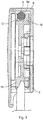
- Fig. 3 is a sectional view of a pulley case 8 shown in Fig. 2 taken along line A-A.;
- slats 3 are supported by ladder cords 2 which are supported by a head box 1 so as to suspend therefrom, and a bottom rail 4 is disposed at bottom ends of the ladder cords 2.
- Hoisting cords 5 are inserted in the slats 3 at positions near supporting positions of the ladder cords 2.
- the bottom rail 4 is supported by bottom ends of the hoisting cords 5 so as to suspend therefrom.
- Top ends of the hoisting cords 5 are wound around a winding shaft 7 which is supported so as to be rotatable by a supporting member disposed in the head box 1.
- a pulley 16 disposed in a pulley case 8 is supported so as to be rotatable at an end of the head box 1.
- An operation cord 9 is hung on the pulley 16 such that the operation cord 9 is in a concavity 17 formed on an outer periphery of the pulley 16 so as not to touch the inside 8a of the pulley case 8.
- the winding shaft 7 is rotated via gears in a gear box 10, a hoisting shaft 12a and the like, so that the hoisting cord 5 is wound by the winding shaft 7 or unwound, causing the slats 3 and the bottom rail 4 to move up or down.
- a tilt drum 13 is rotated via gears in the gear box 10, a tilt shaft 12b and the like, so that the respective slats 3 are turned via the ladder cords 2.
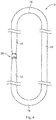
- Fig. 4 is a front view illustrating the operation cord 9 according to the embodiment of the present invention.
- Fig. 5 is a sectional view illustrating a coupling portion 20 constituting the operation cord 9 according to the embodiment of the present invention.
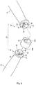
- Fig. 6 is an exploded perspective view illustrating the coupling portion 20 constituting the operation cord 9 according to the embodiment of the present invention.
- the operation cord 9 is formed into an endless shape with both ends of a cord 14 being coupled with each other by means of a coupling portion 20.
- the cord 14 is of a cylindrical shape, and each end thereof has a tapered shape.
- a polyester resin can be preferably used, for example.
- the material for the cord 14 is not specifically limited provided that the material is a thermoplastic resin having strength of a predetermined level or higher, and thus, a resin other than a polyester resin, for example, a polyamide resin, may be used.
- a core made of a polyester resin, a polyamide resin or the like may be coated with an envelope cord woven from a polyester resin. With a cord of this configuration, linearity of the operation cord 9 is ensured thanks to the core, and durability in an extending direction is also ensured.
- the coupling portion 20 is composed of a first joint body 40, a second joint body 41 which is of the same constitution as the first joint body 40, and a joint ring 42 which is disposed between the first and second joint bodies 40, 41 and connects them.
- the coupling portion 20 in which these three members are formed has a cylindrical shape, and is formed such that an outer diameter, that is, an outer diameter M in a lateral direction, is smaller than a maximum diameter P of the cord 14. Note, however, that the outer diameter M of the coupling portion 20 may be equal to the maximum diameter P of the cord 14. Since the coupling portion 20 is configured as described above, when the operation cord 9 is operated to rotate the pulley 16 shown in Fig.
- a tip of each tapered end of the cord 14, which is made of a thermoplastic resin, is provided with a flange 30 configured to fit with the first joint body 40 or the second joint body 41.
- the flange 30 is formed into a ring which has a diameter greater than that of the smallest portion on a tip side of the tapered end and smaller than the maximum diameter P.
- the flange 30 is for ensuring sufficient joint force with the first joint body 40 or the second joint body 41, so that a shape of the flange 30 is not limited particularly, provided that sufficient joint force is ensured, and thus, the flange 3 may have a shape of a gear or the like.
- the outer diameter R1 of the flange 30 is set between 1.05 to 1.3 times a smallest diameter R2 of the cord 14. It is preferable that a value of R1 / R2 is between 1.1 to 1.2 in view of ease of forming the flange 30 and strength of outsert molding of the first joint body 40 and the second joint body 41.
- first joint body 40 or the second joint body 41 can be employed in attaching the first joint body 40 or the second joint body 41 to the tip of each end of the cord 14.
- the tip of each end of the cord 14 is heated while being compressed, and the ring-shaped flange 30 is formed using a mold prepared beforehand.
- the first joint body 40 or the second joint body 41 is formed by means of outsert molding so as to cover the flange 30.
- outsert molding each end of the cord 14 is fixed to the first joint body 40 or the second joint body 41 with enhanced joint force.
- the method of integrating the first joint body 40 or the second joint body 41 with the cord 14 is not limited to the method described above.
- the first joint body 40 or the second joint body 41 is formed first, and thereafter the flange 30 formed at each end of the cord 14 is fitted in the first joint body 40 or the second joint body 41.
- the cord 14 is provided with reduced diameter portions 35 between each of the flanges 30 and a portion of the maximum diameter P of the cord 14, where the diameter is gradually reduced as a distance to the flange 30 decreases. Therefore, each end of the cord 14 can be easily coupled with the first joint body 40 or the second joint body 41 constituting the coupling portion 20, and the outer diameter M of the coupling portion 20 in the lateral direction can be easily made equal to or smaller than the maximum diameter P of the cord 14.
- Fig. 7 is an enlarged front view illustrating the first joint body 40 or the second joint body 41 constituting the coupling portion 20 shown in Figs. 5 and 6 .
- Fig. 8 is an enlarged plan view illustrating the first joint body 40 or the second joint body 41 constituting the coupling portion 20 shown in Figs. 5 and 6 .
- Fig. 9 is an enlarged side view illustrating the first joint body 40 or the second joint body 41 constituting the coupling portion 20 shown in Figs. 5 and 6 .
- Fig. 10 is a sectional view taken along line B-B in Fig. 7 .
- the first joint body 40 and the second joint body 41 are formed of a same synthetic resin at the both ends of the cord 14.
- a fitting protrusion 45 of a round shank shape is formed at each of the tips of the first joint body 40 and the second joint body 41.
- two swelled portions 46 are formed line symmetrically with regard to a center of the round shank so as to have a greater outer diameter.
- a locking concavity 47 which is a concavity having a semicircular cross section.
- chamfered edges 54 are formed on a front end side and a base end side of the swelled portion 46.
- a cross section of the swelled portion 46, cut along a central axis, has a trapezoidal shape due to the chamfered edges 54, 54.
- rotation restriction portions 48 protruding in radial directions of the round shank are formed line symmetrically with regard to the center.
- Each of the rotation restriction portions 48 is formed at a position shifted by 45 degrees from the locking concavity 47 in a circumferential direction with regard to the center of the round shank.
- Fig. 11 is an enlarged front view illustrating the joint ring 42 constituting the coupling portion 20 shown in Figs. 5 and 6 .
- Fig. 12 is an enlarged rear view illustrating the joint ring 42 constituting the coupling portion 20 shown in Figs. 5 and 6 .
- Fig. 13 is a sectional view taken along line C-C in Fig. 11 .
- Fig. 14 is a sectional view taken along line D-D in Fig. 11 .
- Fig. 15 is a sectional view taken along line E-E in Fig. 13 .
- Fig. 16 is a sectional view illustrating a fitting state of the first joint body 40 or the second joint body 41 with the joint ring 42.
- the joint ring 42 is formed entirely into a cylindrical shape. As shown in Figs. 11 and 12 , openings 49a, 49b on both sides of the joint ring 42 are each formed generally into a rectangular shape in order to allow the tip of the fitting protrusion 45 including the swelled portion 46 to be inserted therein. Additionally, the openings 49a, 49b are so formed that longitudinal directions of the rectangles are rotated by 90 degrees from each other with regard to a center of a cylinder.
- a circular hole (fitting hole) 50 is formed having a diameter which allows the tip of the fitting protrusion 45 to rotate.
- the circular hole 50 has a center which is identical with a center of the outer diameter of the joint ring 42.
- a locking portion 51a, 51b is formed which constitutes a first locking portion for preventing the swelled portion 46 from dropping off the circular hole 50. Also, as shown in Fig.
- a locking portion 51c, 51d is formed which constitutes a second locking portion for preventing the swelled portion 46 from dropping off the circular hole 50.
- the first locking portion 51a, 51b and the second locking portion 51c, 51d are arranged, within the both openings 49a, 49b of the circular hole 50, mirror symmetrically such that they are rotationally shifted by 90 degrees from each other. Note, however, that the angle is not limited to 90 degrees.
- chamfered edges 52 are provided at boundaries of the first locking portion 51a, 51b and the second locking portion 51c, 51d with the circular hole 50, so that when the fitting protrusion 45 is pulled out of the circular hole 50, that is, when a fast and furious force is applied and separation at the coupling portion 20 occurs, the locking portions 51a to 51d are prevented from being damaged thanks to working of the chamfered edges 52.
- a locking protrusion 53a protruding inward in a radial direction is formed on the inside of the first locking portion 51a
- a locking protrusion 53b protruding inward in a radial direction is formed on the inside of the second locking portion 51c. That is, a locking protrusion 53a, 53b configured to engage with the locking concavity 47 is formed on an inner peripheral surface of each of the circular holes 50.
- the locking concavity 47 of the fitting protrusion 45 engages with the locking protrusion 53a in the circular hole 50, one of the rotation restriction portions 48 moves from a side of one second locking portion 51c to a side of another second locking portion 51d so as to abut the second locking portion 51d, and the other of the rotation restriction portions 48 moves from the side of the other second locking portion 51d to the side of the one second locking portion 51c so as to abut the second locking portion 51c, and thus, they are positioned as shown in Fig. 16 .
- the second joint body 41 is similarly inserted in the other opening 49a of the joint ring 42 and then relatively rotated by 90 degrees, so that they are positioned. As a result, as shown in Fig. 5 , the first joint body 40 and the second joint body 41 are coupled with each other via the joint ring 42.
- a force for this holding is so set that the fitting protrusion 45 never drops out of the joint ring 42 with a normal pull force applied to the operation cord 9 during a normal operation for moving the slats up and down and adjusting the angle of the slats.
- the openings 49a, 49b of the joint ring 42 are expanded in the radial directions by the swelled portions 46 of the fitting protrusions 45 due to resiliency of the synthetic resin of the joint ring 42, so that the fitting protrusion 45 drops out of the joint ring 42.
- either one of the first joint body 40 and the second joint body 41 first drops out of the joint ring 42. Therefore, a state arises where the joint ring 42 is engaged with one of the first joint body 40 and the second joint body 41, and thus, the joint ring 42 never drops off the operation cord 9.
- the operation cord 9 configured as described above can be rotated unlimitedly and smoothly relative to the pulley 16 and is equipped with a failsafe function. After the fitting at the coupling portion 20 is broken, the first joint body 40 or the second joint body 41 can be fitted in the joint ring 42 again, so that the endless operation cord 9 is easily reconstructed. Further, since a configuration is adopted where the fitting protrusion 45 is inserted in the opening 49a, 49b of the joint ring 42 and subsequently rotated by 90 degrees to achieve the fitting of the fitting protrusion 45 with the joint ring 42, it is possible to minimize the operation force needed for fitting the fitting protrusion 45 with the joint ring 42.
- the elevation apparatus employing the operation cord 9 according to one embodiment of the present invention can be suitably used for a light shielding apparatus such as, in addition to the horizontal blind shown in Fig. 1 , a shade, a blind of another type, and a curtain.
- the elevation apparatus of the present invention, with the operation cord 9 being provided, is not only easy to handle but also free from a potential risk caused by an operation cord.
- a horizontal blind has been described thus far, as a preferable embodiment of the operation cord 9 and the elevation apparatus using the same according to the present invention, however, the present invention is not limited to the embodiment shown above, but can be implemented in variously altered forms.
- Fig. 17 is an exploded perspective view illustrating a coupling portion 60 of an operation cord according to another embodiment of the present invention.
- Fig. 18 is a sectional view of a major part of the coupling portion 60 shown in Fig. 17 .
- the coupling portion 60 may comprise two members, that is, an integrated portion 61 configured as if the first joint body 40 and the joint ring 42 are integrated together, and the second joint body 41. Both ends of the cord 14 are provided with the second joint body 41 and the integrated portion 61, respectively, via the respective flanges 30.
- a step having a cross-section of a right angle may be provided in place of the chamfered edge 52 in the joint ring 42.
- two members are provided for each of the swelled portion 46, the locking concavity 47, the first locking portion 51a, 51b and the second locking portion 51c, 51d, one member of three or more members may be provided for each of them. In this case, a value other than 90 degrees is preferably employed for the rotation angle.
- the cord 14 may be formed of a resin other than a thermoplastic resin or of braided threads. Though each end of the cord 14 is formed into the reduced diameter portion 35 which is gradually reduced in diameter size, it may be formed into a small diameter portion 35 having a fixed diameter from a certain point to the tip. Further, the end may be formed by means of outsert molding without providing the flange 30.
- connection of the cord 14 and the first joint body 40 or the integrated portion 61, or the connection of the cord 14 and the second joint body 41 may be established by a method other than outsert molding, for example, by bonding with an adhesive agent.
- the outer diameters of the first joint body 40, the second joint body 41, and the joint ring 42 are all made equal to the outer diameter of the coupling portion 20 in the lateral direction
- a configuration may be employed where only one or two of the two members or three members are made larger to have a diameter equal to the diameter M of the coupling portion 20, and remaining one or two members are made to have a smaller diameter.
- these three or two members are molded from a synthetic resin, they may be made of another material, such as a metallic material.
Landscapes
- Engineering & Computer Science (AREA)
- Structural Engineering (AREA)
- Architecture (AREA)
- Civil Engineering (AREA)
- Blinds (AREA)
Description
- The present invention is related to an operation cord suitably used in a horizontal blind, a vertical blind, a shade, a screen window, an up-down sliding window, an awning, a skylight window, a laundry pole and the like, and to an elevation apparatus employing the same.
- A kind of a horizontal blind is known where an endless-type operation cord is engaged with a pulley that is supported so as to be rotatable at an end of a head box, and the operation cord is operated to rotate the pulley so that operations for moving slats up and down and adjusting their angle are enabled. Further, a technique is known in which an operation cord is wound around a pulley to operate a vertical blind (see Patent Document 1).
- Such an operation cord is formed to be endless through fusing or stitching together both ends of a cord which is formed of a synthetic resin into a string shape. The operation cord of this type is engaged with a concavity formed on a peripheral surface of the pulley without touching the inside of a pulley case in which the pulley is disposed so that the operation cord can rotate the pulley.
- When the endless-type operation cord mentioned above is hanging down from the pulley, part of the endless operation cord sometimes catches a dweller moving in the room or another moving object. Especially, if the operation cord catches a child or an aged person, a dangerous situation easily occurs in which the operation cord tangles around the neck, or the child or the aged person falls down. As a countermeasure against this problem, the following operation cord is proposed. That is, an operation cord which is used in an arrangement where a supporting frame for suspending a light shielding member such as a shade, a blind or a curtain is disposed on a wall surface around a window, to open and close the suspending light shielding member horizontally or vertically, and hanging down from the supporting frame, is provided with a safety member which can be attached and detached and is configured to be deconstructed when a fast and furious force is applied in an extending direction of the operation cord (see Patent Document 2).
-
- Patent Document 1:
JP-A-05-010081 - Patent Document 2:
JP-A-2003-184456 - Patent Document 3:
JP-A-2007-177440 - However, with the operation cord disclosed in
Patent Document - Accordingly, the present invention is made to solve the above-mentioned problem, and the object thereof is to enable smooth rotation of an operation cord and to provide an operation cord equipped with a failsafe function and an elevation apparatus employing the operation cord.
- To achieve the object, an operation cord according to
claim 1 is suggested. - In the operation cord of the above-mentioned configuration, the coupling portion cannot be a hindrance during rotation, so that the operation cord is rotated smoothly. Further, through adjustment of a coupling force of the coupling portion, the operation cord can be divided at the coupling portion when a fast and furious force is applied in an extending direction of the operation cord, so that the operation cord is equipped with a failsafe function.
- According to a further embodiment, in the above-mentioned invention, each end of the cord is so formed that a diameter thereof gets smaller as a distance to the coupling portion decreases.
- In the operation cord of the above configuration, each end of the cord can be surely connected to the coupling portion, and it is easy to make the outer diameter of the coupling portion in the lateral direction equal to or smaller than the maximum diameter of the cord.
- According to a further embodiment, in the above-mentioned invention, a length of the coupling portion in a longitudinal direction is at least 1.2 times the maximum diameter of the cord and at most 2.5 times the maximum diameter of the cord.
- In the operation cord of the above configuration, the coupling portion is prevented from touching the inside of the pulley case so that the pulley can be rotated smoothly.
- According to a further embodiment, in the above-mentioned invention, the coupling portion comprises a first joint body provided at one end of the cord, a second joint body provided at another end of the cord, and a joint ring provided between the first joint body and the second joint body, wherein the first joint body and the second joint body each have a fitting protrusion of an axial shape, the joint ring has fitting holes each configured to fit with the fitting protrusion, the fitting protrusion is configured to engage with the fitting hole through being inserted in the fitting hole and subsequently rotated, and the first joint body, the second joint body and the joint ring are each so configured that an outer diameter thereof in a lateral direction is equal to or smaller than the maximum diameter of the cord.
- In the operation cord of the above configuration, the operation cord can be rotated smoothly, and an operation cord equipped with a failsafe function is realized. That is, the coupling portion of the operation cord, which is formed to have an outer diameter in the lateral direction equal to or smaller than the maximum diameter of the cord, seldom touches the inside of the pulley case or the like. Further, the coupling portion is prevented from getting hung up in a concavity or the like formed on a peripheral surface of the pulley. Moreover, the coupling portion is provided with the first joint body, the second joint body and the joint ring disposed between the first joint body and the second joint body, and each of the fitting protrusions provided in the first joint body and the second joint body can engage with the fitting hole provided in the joint ring through being inserted in the fitting hole and subsequently rotated, so that it is possible to make fitting of the fitting protrusion of the coupling portion with the fitting hole break easily, when a great pull force exceeding a normal pull force is applied to the operation cord. Accordingly, when part of the endless operation cord catches a dweller moving in the room or another moving object, it is easy to cut the operation cord at the coupling portion to ensure safety, and to obviate damaging the pulley or the like with which the operation cord is engaged.
- According to a further embodiment, in the above-mentioned invention, a fitting position of the fitting protrusion and the fitting hole is set at a position to which the fitting protrusion is brought through a rotation by 90 degrees after inserted in the fitting hole.
- In the operation cord of the above configuration, it is possible to ensure a sufficient holding force to hold the fitting protrusion in the fitting hole, while minimizing an operation force to make the fitting protrusion fit in the fitting hole.
- According to a further embodiment, in the above-mentioned invention, the first joint body and the second joint body are each formed at one end or another end of the cord by means of outsert molding.
- In the operation cord of the above configuration, joint force of each of the first joint body and the second joint body with the cord can be enhanced.
- According to a further embodiment, in the above-mentioned invention, the cord is made of a thermoplastic resin, and a tip of each end of the cord is provided with a flange configured to fit with the first joint body or the second joint body.
- In the operation cord of the above configuration, it is possible to ensure sufficient joint force of each of the first joint body and the second joint body with the cord by way of each flange.
- According to a further embodiment, in the above-mentioned invention, the first joint body, the second joint body and the joint ring are molded from a synthetic resin, the fitting protrusion is provided with swelled portions each having a diameter greater than a diameter of a base end of the fitting protrusion, and the fitting hole is provided with a first locking portion and a second locking portion each configured to engage with the swelled portion.
- In the operation cord of the above configuration, the swelled portions of the fitting protrusion can be fit and held resiliently in the first locking portion and the second locking portion. As a result, it is possible to ensure a sufficient holding force to hold the fitting protrusion in the fitting hole.
- According to a further embodiment, in the above-mentioned invention, the first locking portion and the second locking portion are provided mirror symmetrically within openings of the fitting holes so as to be rotationally shifted from each other by 90 degrees.
- In the operation cord of the above configuration, the first joint body and the second joint body each fitted in the joint ring are held in a state where their fitting protrusions are rotationally shifted from each other by 90 degrees. Therefore, when a pull force is applied to each of the fitting protrusions, the swelled portions of the both fitting protrusions work, by way of the first locking portion and the second locking portion, on the openings of the joint ring so as to push out them in directions shifted from each other by 90 degrees. Therefore, it is easy to ensure a sufficient holding force.
- According to a further embodiment, in the above-mentioned invention, the swelled portion and an inner peripheral surface of the fitting hole are provided with positioning means for determining a rotational position of the fitting protrusion.
- In the operation cord of the above configuration, through determining the rotational position of the fitting protrusion, it is possible to ensure a sufficient holding force to hold the fitting protrusion in the fitting hole.
- According to a further embodiment, an elevation apparatus comprises the operation cord of any one of
claims 1 to 9. - In the elevation apparatus of the above configuration, the operation cord can be rotated smoothly and, at the same time, a failsafe function is equipped.
- According to the present invention, smooth rotation of the operation cord is enabled, and an operation cord equipped with a failsafe function and an elevation apparatus employing the operation cord are provided.
-
-
Fig. 1 is a view illustrating a horizontal blind employing an operation cord according to an embodiment of the present invention; -
Fig. 2 is an enlarged view of an operation section on the right side of the horizontal blind shown inFig. 1 ; -
Fig. 3 is a sectional view of a pulley case shown inFig. 2 taken along line A-A.; -
Fig. 4 is a front view illustrating the operation cord according to the embodiment of the present invention; -
Fig. 5 is a sectional view illustrating a coupling portion constituting the operation cord according to the embodiment of the present invention; -
Fig. 6 is an exploded perspective view illustrating the coupling portion constituting the operation cord according to the embodiment of the present invention; -
Fig. 7 is an enlarged front view illustrating a first joint body or a second joint body constituting the coupling portion shown inFigs. 5 and6 ; -
Fig. 8 is an enlarged plan view illustrating the first joint body or the second joint body constituting the coupling portion shown inFigs. 5 and6 ; -
Fig. 9 is an enlarged side view illustrating the first joint body or the second joint body constituting the coupling portion shown inFigs. 5 and6 ; -
Fig. 10 is a sectional view taken along line B-B inFig. 7 ; -
Fig. 11 is an enlarged front view illustrating a joint ring constituting the coupling portion shown inFigs. 5 and6 ; -
Fig. 12 is an enlarged rear view illustrating the joint ring constituting the coupling portion shown inFigs. 5 and6 ; -
Fig. 13 is a sectional view taken along line C-C inFig. 11 ; -
Fig. 14 is a sectional view taken along line D-D inFig. 11 ; -
Fig. 15 is a sectional view taken along line E-E inFig. 13 ; -
Fig. 16 is a sectional view illustrating a fitting state of the first or second joint body with the joint ring; -
Fig. 17 is an exploded perspective view illustrating a coupling portion of an operation cord according to another embodiment of the present invention; and -
Fig. 18 is a sectional view of a major part of the coupling portion shown inFig. 17 . - Hereafter, preferred embodiments of an operation cord according to the present invention and an elevation apparatus employing the operation cord will be described in detail with reference to the drawings. However, the present invention is not limited to any of the following preferred embodiments by any means.
-
Fig. 1 illustrates a horizontal blind employing anoperation cord 9 according to an embodiment of the present invention, where (A) is a front view and (B) is a plan view.Fig. 2 is an enlarged view of an operation section on the right side of the horizontal blind shown inFig. 1 .Fig. 3 is a sectional view of apulley case 8 shown inFig. 2 taken along line A-A.; - In the horizontal blind shown in
Fig. 1 ,multiple slats 3 are supported byladder cords 2 which are supported by ahead box 1 so as to suspend therefrom, and abottom rail 4 is disposed at bottom ends of theladder cords 2. - Hoisting
cords 5 are inserted in theslats 3 at positions near supporting positions of theladder cords 2. Thebottom rail 4 is supported by bottom ends of thehoisting cords 5 so as to suspend therefrom. Top ends of thehoisting cords 5 are wound around a windingshaft 7 which is supported so as to be rotatable by a supporting member disposed in thehead box 1. - As shown in
Figs. 2 and3 , apulley 16 disposed in apulley case 8 is supported so as to be rotatable at an end of thehead box 1. Anoperation cord 9 is hung on thepulley 16 such that theoperation cord 9 is in aconcavity 17 formed on an outer periphery of thepulley 16 so as not to touch the inside 8a of thepulley case 8. When theoperation cord 9 is operated to rotate thepulley 16 in a forward or reverse direction, the windingshaft 7 is rotated via gears in agear box 10, a hoistingshaft 12a and the like, so that thehoisting cord 5 is wound by the windingshaft 7 or unwound, causing theslats 3 and thebottom rail 4 to move up or down. - When the
pulley 16 is rotated, atilt drum 13 is rotated via gears in thegear box 10, atilt shaft 12b and the like, so that therespective slats 3 are turned via theladder cords 2. -
Fig. 4 is a front view illustrating theoperation cord 9 according to the embodiment of the present invention.Fig. 5 is a sectional view illustrating acoupling portion 20 constituting theoperation cord 9 according to the embodiment of the present invention.Fig. 6 is an exploded perspective view illustrating thecoupling portion 20 constituting theoperation cord 9 according to the embodiment of the present invention. - As shown in
Fig. 4 , theoperation cord 9 is formed into an endless shape with both ends of acord 14 being coupled with each other by means of acoupling portion 20. Thecord 14 is of a cylindrical shape, and each end thereof has a tapered shape. For thecord 14, a polyester resin can be preferably used, for example. However, the material for thecord 14 is not specifically limited provided that the material is a thermoplastic resin having strength of a predetermined level or higher, and thus, a resin other than a polyester resin, for example, a polyamide resin, may be used. Further, a core made of a polyester resin, a polyamide resin or the like may be coated with an envelope cord woven from a polyester resin. With a cord of this configuration, linearity of theoperation cord 9 is ensured thanks to the core, and durability in an extending direction is also ensured. - As shown in
Figs. 5 and6 , thecoupling portion 20 is composed of a firstjoint body 40, a secondjoint body 41 which is of the same constitution as the firstjoint body 40, and ajoint ring 42 which is disposed between the first and secondjoint bodies coupling portion 20 in which these three members are formed has a cylindrical shape, and is formed such that an outer diameter, that is, an outer diameter M in a lateral direction, is smaller than a maximum diameter P of thecord 14. Note, however, that the outer diameter M of thecoupling portion 20 may be equal to the maximum diameter P of thecord 14. Since thecoupling portion 20 is configured as described above, when theoperation cord 9 is operated to rotate thepulley 16 shown inFig. 3 in a forward or reverse direction, thecoupling portion 20 of theoperation cord 9, which is so formed as to have the outer diameter M in the lateral direction equal to or smaller than the maximum diameter P of thecord 14, seldom touches the inside 8a of thepulley case 8. Further, thecoupling portion 20 hardly gets hung up in aconcavity 17 formed on the peripheral surface of thepulley 16. As a result, smooth rotation of theoperation cord 9 is possible. Moreover, thecoupling portion 20 is so formed that a longitudinal length thereof is at least 1.2 times the maximum diameter P of thecord 14 and at most 2.5 times the maximum diameter P of thecord 14. When the maximum diameter P of thecord 14 is 5.5 mm, for example, the length of thecoupling portion 20 may be 7 mm. Thus, thecoupling portion 20 does not touches the inside 8a of thepulley case 8, so that thepulley 16 can be rotated more smoothly. - Further, a tip of each tapered end of the
cord 14, which is made of a thermoplastic resin, is provided with aflange 30 configured to fit with the firstjoint body 40 or the secondjoint body 41. In this embodiment, as shown inFig. 5 , theflange 30 is formed into a ring which has a diameter greater than that of the smallest portion on a tip side of the tapered end and smaller than the maximum diameter P. Theflange 30 is for ensuring sufficient joint force with the firstjoint body 40 or the secondjoint body 41, so that a shape of theflange 30 is not limited particularly, provided that sufficient joint force is ensured, and thus, theflange 3 may have a shape of a gear or the like. Moreover, the outer diameter R1 of theflange 30 is set between 1.05 to 1.3 times a smallest diameter R2 of thecord 14. It is preferable that a value of R1 / R2 is between 1.1 to 1.2 in view of ease of forming theflange 30 and strength of outsert molding of the firstjoint body 40 and the secondjoint body 41. - Various methods can be employed in attaching the first
joint body 40 or the secondjoint body 41 to the tip of each end of thecord 14. For example, firstly, the tip of each end of thecord 14 is heated while being compressed, and the ring-shapedflange 30 is formed using a mold prepared beforehand. Subsequently, the firstjoint body 40 or the secondjoint body 41 is formed by means of outsert molding so as to cover theflange 30. Through such outsert molding, each end of thecord 14 is fixed to the firstjoint body 40 or the secondjoint body 41 with enhanced joint force. Note, however, that the method of integrating the firstjoint body 40 or the secondjoint body 41 with thecord 14 is not limited to the method described above. For example, the firstjoint body 40 or the secondjoint body 41 is formed first, and thereafter theflange 30 formed at each end of thecord 14 is fitted in the firstjoint body 40 or the secondjoint body 41. - Further, as shown in
Fig. 5 , thecord 14 is provided with reduceddiameter portions 35 between each of theflanges 30 and a portion of the maximum diameter P of thecord 14, where the diameter is gradually reduced as a distance to theflange 30 decreases. Therefore, each end of thecord 14 can be easily coupled with the firstjoint body 40 or the secondjoint body 41 constituting thecoupling portion 20, and the outer diameter M of thecoupling portion 20 in the lateral direction can be easily made equal to or smaller than the maximum diameter P of thecord 14. -
Fig. 7 is an enlarged front view illustrating the firstjoint body 40 or the secondjoint body 41 constituting thecoupling portion 20 shown inFigs. 5 and6 .Fig. 8 is an enlarged plan view illustrating the firstjoint body 40 or the secondjoint body 41 constituting thecoupling portion 20 shown inFigs. 5 and6 .Fig. 9 is an enlarged side view illustrating the firstjoint body 40 or the secondjoint body 41 constituting thecoupling portion 20 shown inFigs. 5 and6 .Fig. 10 is a sectional view taken along line B-B inFig. 7 . - As shown in
Figs. 6 to 10 , the firstjoint body 40 and the secondjoint body 41 are formed of a same synthetic resin at the both ends of thecord 14. Afitting protrusion 45 of a round shank shape is formed at each of the tips of the firstjoint body 40 and the secondjoint body 41. - On an outer peripheral surface of a tip of the
fitting protrusion 45, two swelledportions 46 are formed line symmetrically with regard to a center of the round shank so as to have a greater outer diameter. At a middle in a radial direction of each of the swelledportions 46 is formed a lockingconcavity 47 which is a concavity having a semicircular cross section. Further, chamfered edges 54 are formed on a front end side and a base end side of the swelledportion 46. A cross section of the swelledportion 46, cut along a central axis, has a trapezoidal shape due to the chamfered edges 54, 54. - At a base end of the
fitting protrusion 45, that is, on the side to theflange 30, as shown inFigs. 6 and10 ,rotation restriction portions 48 protruding in radial directions of the round shank are formed line symmetrically with regard to the center. Each of therotation restriction portions 48 is formed at a position shifted by 45 degrees from the lockingconcavity 47 in a circumferential direction with regard to the center of the round shank. -
Fig. 11 is an enlarged front view illustrating thejoint ring 42 constituting thecoupling portion 20 shown inFigs. 5 and6 .Fig. 12 is an enlarged rear view illustrating thejoint ring 42 constituting thecoupling portion 20 shown inFigs. 5 and6 .Fig. 13 is a sectional view taken along line C-C inFig. 11 .Fig. 14 is a sectional view taken along line D-D inFig. 11 .Fig. 15 is a sectional view taken along line E-E inFig. 13 .Fig. 16 is a sectional view illustrating a fitting state of the firstjoint body 40 or the secondjoint body 41 with thejoint ring 42. - The
joint ring 42 is formed entirely into a cylindrical shape. As shown inFigs. 11 and 12 ,openings joint ring 42 are each formed generally into a rectangular shape in order to allow the tip of thefitting protrusion 45 including the swelledportion 46 to be inserted therein. Additionally, theopenings - Within the
joint ring 42, a circular hole (fitting hole) 50 is formed having a diameter which allows the tip of thefitting protrusion 45 to rotate. Thecircular hole 50 has a center which is identical with a center of the outer diameter of thejoint ring 42. Further, at each of opening edges, in a shorter-axis direction, of the laterally long opening 49a shown inFig. 11 , a lockingportion portion 46 from dropping off thecircular hole 50. Also, as shown inFig. 12 , at each of opening edges, in a shorter-axis direction, of the longitudinallylong opening 49b, a lockingportion portion 46 from dropping off thecircular hole 50. Thefirst locking portion second locking portion openings circular hole 50, mirror symmetrically such that they are rotationally shifted by 90 degrees from each other. Note, however, that the angle is not limited to 90 degrees. Therefore, when a pull force is applied to each of thefitting protrusions 45 in directions to separate them away from each other, though the swelledportions 46 of eachfitting protrusion 45 act on theopenings - As shown in
Figs. 13 and 14 , chamfered edges 52 are provided at boundaries of thefirst locking portion second locking portion circular hole 50, so that when thefitting protrusion 45 is pulled out of thecircular hole 50, that is, when a fast and furious force is applied and separation at thecoupling portion 20 occurs, the lockingportions 51a to 51d are prevented from being damaged thanks to working of the chamfered edges 52. - Further, a locking
protrusion 53a protruding inward in a radial direction is formed on the inside of thefirst locking portion 51a, and a lockingprotrusion 53b protruding inward in a radial direction is formed on the inside of thesecond locking portion 51c. That is, a lockingprotrusion concavity 47 is formed on an inner peripheral surface of each of the circular holes 50. To couple the firstjoint body 40 and thejoint ring 42, thefitting protrusion 45 of the firstjoint body 40 is inserted in theopening 49b of thejoint ring 42, and then the firstjoint body 40 is rotated by 90 degrees with respect to thejoint ring 42 in a counter clockwise direction, as seen from theopening 49a. As a result, the lockingconcavity 47 of thefitting protrusion 45 engages with the lockingprotrusion 53a in thecircular hole 50, one of therotation restriction portions 48 moves from a side of onesecond locking portion 51c to a side of anothersecond locking portion 51d so as to abut thesecond locking portion 51d, and the other of therotation restriction portions 48 moves from the side of the othersecond locking portion 51d to the side of the onesecond locking portion 51c so as to abut thesecond locking portion 51c, and thus, they are positioned as shown inFig. 16 . - Also, the second
joint body 41 is similarly inserted in theother opening 49a of thejoint ring 42 and then relatively rotated by 90 degrees, so that they are positioned. As a result, as shown inFig. 5 , the firstjoint body 40 and the secondjoint body 41 are coupled with each other via thejoint ring 42. - In this state, the swelled
portions 46 of each of thefitting protrusions 45 of the firstjoint body 40 and the secondjoint body 41 engage with each of the lockingportions 51a to 51d of thejoint ring 42, and are held within thecircular holes 50 of thejoint ring 42. - A force for this holding is so set that the
fitting protrusion 45 never drops out of thejoint ring 42 with a normal pull force applied to theoperation cord 9 during a normal operation for moving the slats up and down and adjusting the angle of the slats. Moreover, only when a great force exceeding the normal pull force is applied to theoperation cord 9, theopenings joint ring 42 are expanded in the radial directions by the swelledportions 46 of thefitting protrusions 45 due to resiliency of the synthetic resin of thejoint ring 42, so that thefitting protrusion 45 drops out of thejoint ring 42. In this process, either one of the firstjoint body 40 and the secondjoint body 41 first drops out of thejoint ring 42. Therefore, a state arises where thejoint ring 42 is engaged with one of the firstjoint body 40 and the secondjoint body 41, and thus, thejoint ring 42 never drops off theoperation cord 9. - The
operation cord 9 configured as described above can be rotated unlimitedly and smoothly relative to thepulley 16 and is equipped with a failsafe function. After the fitting at thecoupling portion 20 is broken, the firstjoint body 40 or the secondjoint body 41 can be fitted in thejoint ring 42 again, so that theendless operation cord 9 is easily reconstructed. Further, since a configuration is adopted where thefitting protrusion 45 is inserted in theopening joint ring 42 and subsequently rotated by 90 degrees to achieve the fitting of thefitting protrusion 45 with thejoint ring 42, it is possible to minimize the operation force needed for fitting thefitting protrusion 45 with thejoint ring 42. - Moreover, since the pulling force in the direction of the axis of the swelled
portion 46 is sustained by each of the lockingportions 51a to 51d, it is possible to make the holding force to hold thefitting protrusion 45 in thejoint ring 42 sufficiently strong. Also, when the lockingprotrusion concavity 47, the position can be certainly maintained since the positioning is realized by working of therotation restriction portion 48. - The elevation apparatus employing the
operation cord 9 according to one embodiment of the present invention can be suitably used for a light shielding apparatus such as, in addition to the horizontal blind shown inFig. 1 , a shade, a blind of another type, and a curtain. The elevation apparatus of the present invention, with theoperation cord 9 being provided, is not only easy to handle but also free from a potential risk caused by an operation cord. - A horizontal blind has been described thus far, as a preferable embodiment of the
operation cord 9 and the elevation apparatus using the same according to the present invention, however, the present invention is not limited to the embodiment shown above, but can be implemented in variously altered forms. -
Fig. 17 is an exploded perspective view illustrating acoupling portion 60 of an operation cord according to another embodiment of the present invention.Fig. 18 is a sectional view of a major part of thecoupling portion 60 shown inFig. 17 . As shown inFigs. 17 and 18 , thecoupling portion 60 may comprise two members, that is, anintegrated portion 61 configured as if the firstjoint body 40 and thejoint ring 42 are integrated together, and the secondjoint body 41. Both ends of thecord 14 are provided with the secondjoint body 41 and the integratedportion 61, respectively, via therespective flanges 30. - Further, a step having a cross-section of a right angle may be provided in place of the chamfered
edge 52 in thejoint ring 42. Though two members are provided for each of the swelledportion 46, the lockingconcavity 47, thefirst locking portion second locking portion - Moreover, the
cord 14 may be formed of a resin other than a thermoplastic resin or of braided threads. Though each end of thecord 14 is formed into the reduceddiameter portion 35 which is gradually reduced in diameter size, it may be formed into asmall diameter portion 35 having a fixed diameter from a certain point to the tip. Further, the end may be formed by means of outsert molding without providing theflange 30. - Further, the arrangement or the number of the
coupling portion cord 14 and the firstjoint body 40 or the integratedportion 61, or the connection of thecord 14 and the secondjoint body 41 may be established by a method other than outsert molding, for example, by bonding with an adhesive agent. - Though, in each of the embodiments described above, the outer diameters of the first
joint body 40, the secondjoint body 41, and thejoint ring 42 are all made equal to the outer diameter of thecoupling portion 20 in the lateral direction, a configuration may be employed where only one or two of the two members or three members are made larger to have a diameter equal to the diameter M of thecoupling portion 20, and remaining one or two members are made to have a smaller diameter. Furthermore, though these three or two members are molded from a synthetic resin, they may be made of another material, such as a metallic material. -
- 1 ... horizontal blind (elevation apparatus); 9 ... operation cord; 14 ... cord; 20 ... coupling portion; 30 ... flange; 40 ... first joint body; 41 ... second joint body; 42 ... joint ring; 45 ... fitting protrusion; 46 ... swelled portion; 47 ... locking concavity (positioning means); 48 ... rotation restriction portion; 50 ... circular hole (fitting hole); 51a, 51b ... first locking portion; 51c, 51d ... second locking portion; 53a, 53b ... locking protrusion (positioning means)
Claims (13)
- An operation cord (9) comprising a cord (14) whose both ends are configured to be coupled with each other by means of a coupling portion (20, 60) so that the operation cord has an endless shape,
characterized in that the coupling portion (20, 60) comprises:(1) a first joint body (40) provided at one end of the cord; a second joint body (41) provided at another end of the cord; and a joint ring (42) provided between the first joint body (40) and the second joint body (41); or (2) an integrated portion provided at one end of the cord and a second joint body (41) provided at another end of the cord, wherein
the first joint body (40) and the second joint body (41) each have a fitting protrusion (45) of an axial shape,
the joint ring (42) and the integrated portion each have a fitting hole (50) configured to fit with the fitting protrusion (45),
the fitting protrusion (45) is configured to engage with the fitting hole (50) through being inserted in the fitting hole (50) and subsequently rotated, and
the first joint body (40), the second joint body (41), the joint ring (42), and the integrated portion are each so formed that an outer diameter thereof in a lateral direction is equal to or smaller than a maximum diameter of the cord. - The operation cord (9) of claim 1, wherein the coupling portion (20, 60) is so formed that an outer diameter thereof in a lateral direction is smaller than a maximum diameter of the cord.
- The operation cord (9) of claim 1 or 2, wherein each end of the cord (14) is so formed that a diameter thereof gets smaller as a distance to the coupling portion (20, 60) decreases.
- The operation cord (9) of any one of claims 1 to 3, wherein a length of the coupling portion (20, 60) in a longitudinal direction is at least 1.2 times the maximum diameter of the cord and at most 2.5 times the maximum diameter of the cord.
- The operation cord (9) of any one of claims 1 to 4, wherein a fitting position of the fitting protrusion (45) and the fitting hole (50) is set at a position to which the fitting protrusion (45) is brought through a rotation by 90 degrees after inserted in the fitting hole (50).
- The operation cord (9) of any one of claims 1 to 5, wherein the first joint body (40) and the second joint body (41) are each formed at the one end or the other end of the cord by means of outsert molding.
- The operation cord (9) of any one of claims 1 to 6, wherein the cord (14) is made of a thermoplastic resin, and
a tip of each end of the cord is provided with a flange configured to fit with the first joint body (40) or the second joint body (41). - The operation cord (9) of any one of claims 1 to 7, wherein the first joint body (40), the second joint body (41) and the joint ring (42) are molded from a synthetic resin,
the fitting protrusion (45) is provided with swelled portions (46) each having a diameter greater than a diameter of a base end of the fitting protrusion (45), and
the fitting hole (50) is provided with a first locking portion (51a, 51b) and a second locking portion (51c, 51d) each configured to engage with the swelled portion (46). - The operation cord (9) of claim 8, wherein the first locking portion (51a, 51b) and the second locking portion (51c, 51d) are provided mirror symmetrically within openings of the fitting holes (50) so as to be rotationally shifted from each other by 90 degrees.
- The operation cord (9) of claim 8 or 9, wherein the swelled portion (46) and an inner peripheral surface of the fitting hole (50) are provided with positioning means (53a, 53b) for determining a rotational position of the fitting protrusion (45).
- An operation cord (9) according to any of claims 1 to 10 wherein the joint ring (42) is so formed to be a cylindrical shape having a fitting hole (50),
the fitting hole (50) is provided with a circular hole having a diameter which allows a tip of a fitting protrusion (45) to rotate,
the fitting hole (50) is provided with a locking portion configured to engage with the fitting protrusion (45),
the joint ring (42) is so formed that an outer diameter thereof in a lateral direction is equal to or smaller than a maximum diameter of the cord, and
the coupling portion (20, 60) couples the both ends of the cord by fitting of the fitting protrusion (45) and the fitting hole (50). - An operation cord (9) according to any of claims 1 to 10 wherein the joint body (40, 41) is provided with a fitting protrusion (45) having a round shank shape on a tip of the joint body,
the fitting protrusion (45) is provided with a swelled portion (46) having a diameter greater than a diameter of a base end of the fitting protrusion (45), and
the joint body (40, 41) is so formed that an outer diameter thereof in a lateral direction is equal to or smaller than a maximum diameter of the cord. - An elevation apparatus comprising the operation cord of any one of claims 1-12.
Applications Claiming Priority (1)
| Application Number | Priority Date | Filing Date | Title |
|---|---|---|---|
| PCT/JP2009/004397 WO2011027407A1 (en) | 2009-09-04 | 2009-09-04 | Operation cord and lifting device using same |
Publications (3)
| Publication Number | Publication Date |
|---|---|
| EP2474701A1 EP2474701A1 (en) | 2012-07-11 |
| EP2474701A4 EP2474701A4 (en) | 2015-05-06 |
| EP2474701B1 true EP2474701B1 (en) | 2017-11-01 |
Family
ID=43648969
Family Applications (1)
| Application Number | Title | Priority Date | Filing Date |
|---|---|---|---|
| EP09848938.8A Not-in-force EP2474701B1 (en) | 2009-09-04 | 2009-09-04 | Operation cord and lifting device using same |
Country Status (4)
| Country | Link |
|---|---|
| EP (1) | EP2474701B1 (en) |
| JP (1) | JPWO2011027407A1 (en) |
| CN (1) | CN102575497B (en) |
| WO (1) | WO2011027407A1 (en) |
Families Citing this family (2)
| Publication number | Priority date | Publication date | Assignee | Title |
|---|---|---|---|---|
| JP7502013B2 (en) * | 2019-10-25 | 2024-06-18 | 立川ブラインド工業株式会社 | Ball Chain |
| EP3954859A4 (en) * | 2019-04-12 | 2022-06-22 | Tachikawa Corporation | BALL CHAIN AND ROLLER DEVICE |
Family Cites Families (15)
| Publication number | Priority date | Publication date | Assignee | Title |
|---|---|---|---|---|
| US1378507A (en) * | 1919-07-19 | 1921-05-17 | Cutler Hammer Mfg Co | Helical-spring belt |
| US2009330A (en) * | 1934-01-09 | 1935-07-23 | James E Tate | Shoe string |
| US2038469A (en) * | 1934-12-27 | 1936-04-21 | Charles A Bannister | Transmission band |
| US2451247A (en) * | 1944-07-29 | 1948-10-12 | Sims Herman | Adjustable locking shoe lace tip |
| JPS5379959U (en) * | 1976-12-07 | 1978-07-03 | ||
| JPS6285747U (en) * | 1985-11-15 | 1987-06-01 | ||
| JP2538726B2 (en) | 1991-07-05 | 1996-10-02 | 株式会社ニチベイ | Vertical blinds |
| CN2145893Y (en) * | 1992-07-27 | 1993-11-10 | 阜宁县晨光机械厂 | Cable connector |
| JP2782508B2 (en) * | 1996-03-29 | 1998-08-06 | 小島繊維工業株式会社 | Rope end fusion splicing method |
| JP2003184456A (en) * | 2001-12-20 | 2003-07-03 | Yokota:Kk | Operating cord for sun shade member |
| JP4438289B2 (en) * | 2002-12-25 | 2010-03-24 | ブリヂストンフローテック株式会社 | Joint structure |
| JP2006070449A (en) * | 2004-08-31 | 2006-03-16 | Toso Co Ltd | Operation code of solar shading device |
| JP2006207788A (en) * | 2005-01-24 | 2006-08-10 | Shinko Kk | Rope connecting joint |
| JP2007177440A (en) * | 2005-12-27 | 2007-07-12 | Tachikawa Blind Mfg Co Ltd | Operation cord connector and method for manufacturing operation cord connector |
| JP4832180B2 (en) * | 2006-06-23 | 2011-12-07 | トーソー株式会社 | Safety mechanism for operation code of solar shading device |
-
2009
- 2009-09-04 EP EP09848938.8A patent/EP2474701B1/en not_active Not-in-force
- 2009-09-04 CN CN200980161177.7A patent/CN102575497B/en not_active Expired - Fee Related
- 2009-09-04 JP JP2011529705A patent/JPWO2011027407A1/en active Pending
- 2009-09-04 WO PCT/JP2009/004397 patent/WO2011027407A1/en not_active Ceased
Non-Patent Citations (1)
| Title |
|---|
| None * |
Also Published As
| Publication number | Publication date |
|---|---|
| CN102575497A (en) | 2012-07-11 |
| EP2474701A4 (en) | 2015-05-06 |
| JPWO2011027407A1 (en) | 2013-01-31 |
| EP2474701A1 (en) | 2012-07-11 |
| WO2011027407A1 (en) | 2011-03-10 |
| CN102575497B (en) | 2015-07-15 |
Similar Documents
| Publication | Publication Date | Title |
|---|---|---|
| AU2010263600B2 (en) | Operation cord and method of manufacturing operation cord | |
| TWI583860B (en) | Window shade, actuating system, and operating method thereof | |
| EP3164565B1 (en) | Window shade and actuating system thereof | |
| JP2015508466A (en) | Window shade and its control module | |
| JP5341637B2 (en) | Operation code | |
| TW201619489A (en) | Window shade and actuating system thereof | |
| CN102859107B (en) | Operation code, and operation device for sunlight shielding device | |
| EP2474701A1 (en) | Operation cord and lifting device using same | |
| JP5577055B2 (en) | Ball chain of operating device | |
| EP2787161B1 (en) | Sunlight-shielding device and device for adjusting lower limit position of bottom rail | |
| JP5514494B2 (en) | Operation cord and lifting device using the same | |
| JP5351349B2 (en) | Operation cord and lifting device using the same | |
| AU2014263713B2 (en) | Cam unit, horizontal blind, and drive unit for sunlight blocking device | |
| JP5719120B2 (en) | Operation code | |
| JP5538599B2 (en) | Endless cord | |
| JP5271859B2 (en) | Ball chain and solar shading device | |
| JP5442331B2 (en) | Ball chain and ball chain manufacturing method | |
| JP5767363B2 (en) | Operation codes and blinds operated by operation codes | |
| JP5752777B2 (en) | Ball chain and blind | |
| JP6345526B2 (en) | Safety tool | |
| KR101549059B1 (en) | Protection device for blind string | |
| JP6778124B2 (en) | Solar shielding device | |
| JP6322464B2 (en) | Guide ring for shield lifting code | |
| JP2017223003A (en) | Roll blind and take-up device | |
| KR200322712Y1 (en) | Carrier for curtain |
Legal Events
| Date | Code | Title | Description |
|---|---|---|---|
| PUAI | Public reference made under article 153(3) epc to a published international application that has entered the european phase |
Free format text: ORIGINAL CODE: 0009012 |
|
| 17P | Request for examination filed |
Effective date: 20120312 |
|
| AK | Designated contracting states |
Kind code of ref document: A1 Designated state(s): AT BE BG CH CY CZ DE DK EE ES FI FR GB GR HR HU IE IS IT LI LT LU LV MC MK MT NL NO PL PT RO SE SI SK SM TR |
|
| DAX | Request for extension of the european patent (deleted) | ||
| RA4 | Supplementary search report drawn up and despatched (corrected) |
Effective date: 20150409 |
|
| RIC1 | Information provided on ipc code assigned before grant |
Ipc: A47H 5/032 20060101ALI20150401BHEP Ipc: E06B 9/326 20060101AFI20150401BHEP |
|
| GRAP | Despatch of communication of intention to grant a patent |
Free format text: ORIGINAL CODE: EPIDOSNIGR1 |
|
| STAA | Information on the status of an ep patent application or granted ep patent |
Free format text: STATUS: GRANT OF PATENT IS INTENDED |
|
| INTG | Intention to grant announced |
Effective date: 20170404 |
|
| GRAS | Grant fee paid |
Free format text: ORIGINAL CODE: EPIDOSNIGR3 |
|
| GRAA | (expected) grant |
Free format text: ORIGINAL CODE: 0009210 |
|
| STAA | Information on the status of an ep patent application or granted ep patent |
Free format text: STATUS: THE PATENT HAS BEEN GRANTED |
|
| AK | Designated contracting states |
Kind code of ref document: B1 Designated state(s): AT BE BG CH CY CZ DE DK EE ES FI FR GB GR HR HU IE IS IT LI LT LU LV MC MK MT NL NO PL PT RO SE SI SK SM TR |
|
| REG | Reference to a national code |
Ref country code: GB Ref legal event code: FG4D |
|
| REG | Reference to a national code |
Ref country code: CH Ref legal event code: EP Ref country code: AT Ref legal event code: REF Ref document number: 942209 Country of ref document: AT Kind code of ref document: T Effective date: 20171115 |
|
| REG | Reference to a national code |
Ref country code: IE Ref legal event code: FG4D |
|
| REG | Reference to a national code |
Ref country code: DE Ref legal event code: R096 Ref document number: 602009049195 Country of ref document: DE |
|
| REG | Reference to a national code |
Ref country code: NL Ref legal event code: MP Effective date: 20171101 |
|
| REG | Reference to a national code |
Ref country code: LT Ref legal event code: MG4D |
|
| REG | Reference to a national code |
Ref country code: AT Ref legal event code: MK05 Ref document number: 942209 Country of ref document: AT Kind code of ref document: T Effective date: 20171101 |
|
| PG25 | Lapsed in a contracting state [announced via postgrant information from national office to epo] |
Ref country code: SE Free format text: LAPSE BECAUSE OF FAILURE TO SUBMIT A TRANSLATION OF THE DESCRIPTION OR TO PAY THE FEE WITHIN THE PRESCRIBED TIME-LIMIT Effective date: 20171101 Ref country code: NL Free format text: LAPSE BECAUSE OF FAILURE TO SUBMIT A TRANSLATION OF THE DESCRIPTION OR TO PAY THE FEE WITHIN THE PRESCRIBED TIME-LIMIT Effective date: 20171101 Ref country code: FI Free format text: LAPSE BECAUSE OF FAILURE TO SUBMIT A TRANSLATION OF THE DESCRIPTION OR TO PAY THE FEE WITHIN THE PRESCRIBED TIME-LIMIT Effective date: 20171101 Ref country code: LT Free format text: LAPSE BECAUSE OF FAILURE TO SUBMIT A TRANSLATION OF THE DESCRIPTION OR TO PAY THE FEE WITHIN THE PRESCRIBED TIME-LIMIT Effective date: 20171101 Ref country code: ES Free format text: LAPSE BECAUSE OF FAILURE TO SUBMIT A TRANSLATION OF THE DESCRIPTION OR TO PAY THE FEE WITHIN THE PRESCRIBED TIME-LIMIT Effective date: 20171101 Ref country code: NO Free format text: LAPSE BECAUSE OF FAILURE TO SUBMIT A TRANSLATION OF THE DESCRIPTION OR TO PAY THE FEE WITHIN THE PRESCRIBED TIME-LIMIT Effective date: 20180201 |
|
| PG25 | Lapsed in a contracting state [announced via postgrant information from national office to epo] |
Ref country code: AT Free format text: LAPSE BECAUSE OF FAILURE TO SUBMIT A TRANSLATION OF THE DESCRIPTION OR TO PAY THE FEE WITHIN THE PRESCRIBED TIME-LIMIT Effective date: 20171101 Ref country code: HR Free format text: LAPSE BECAUSE OF FAILURE TO SUBMIT A TRANSLATION OF THE DESCRIPTION OR TO PAY THE FEE WITHIN THE PRESCRIBED TIME-LIMIT Effective date: 20171101 Ref country code: BG Free format text: LAPSE BECAUSE OF FAILURE TO SUBMIT A TRANSLATION OF THE DESCRIPTION OR TO PAY THE FEE WITHIN THE PRESCRIBED TIME-LIMIT Effective date: 20180201 Ref country code: IS Free format text: LAPSE BECAUSE OF FAILURE TO SUBMIT A TRANSLATION OF THE DESCRIPTION OR TO PAY THE FEE WITHIN THE PRESCRIBED TIME-LIMIT Effective date: 20180301 Ref country code: GR Free format text: LAPSE BECAUSE OF FAILURE TO SUBMIT A TRANSLATION OF THE DESCRIPTION OR TO PAY THE FEE WITHIN THE PRESCRIBED TIME-LIMIT Effective date: 20180202 Ref country code: LV Free format text: LAPSE BECAUSE OF FAILURE TO SUBMIT A TRANSLATION OF THE DESCRIPTION OR TO PAY THE FEE WITHIN THE PRESCRIBED TIME-LIMIT Effective date: 20171101 |
|
| PG25 | Lapsed in a contracting state [announced via postgrant information from national office to epo] |
Ref country code: CY Free format text: LAPSE BECAUSE OF FAILURE TO SUBMIT A TRANSLATION OF THE DESCRIPTION OR TO PAY THE FEE WITHIN THE PRESCRIBED TIME-LIMIT Effective date: 20171101 Ref country code: EE Free format text: LAPSE BECAUSE OF FAILURE TO SUBMIT A TRANSLATION OF THE DESCRIPTION OR TO PAY THE FEE WITHIN THE PRESCRIBED TIME-LIMIT Effective date: 20171101 Ref country code: DK Free format text: LAPSE BECAUSE OF FAILURE TO SUBMIT A TRANSLATION OF THE DESCRIPTION OR TO PAY THE FEE WITHIN THE PRESCRIBED TIME-LIMIT Effective date: 20171101 Ref country code: CZ Free format text: LAPSE BECAUSE OF FAILURE TO SUBMIT A TRANSLATION OF THE DESCRIPTION OR TO PAY THE FEE WITHIN THE PRESCRIBED TIME-LIMIT Effective date: 20171101 Ref country code: SK Free format text: LAPSE BECAUSE OF FAILURE TO SUBMIT A TRANSLATION OF THE DESCRIPTION OR TO PAY THE FEE WITHIN THE PRESCRIBED TIME-LIMIT Effective date: 20171101 |
|
| REG | Reference to a national code |
Ref country code: DE Ref legal event code: R097 Ref document number: 602009049195 Country of ref document: DE |
|
| PG25 | Lapsed in a contracting state [announced via postgrant information from national office to epo] |
Ref country code: PL Free format text: LAPSE BECAUSE OF FAILURE TO SUBMIT A TRANSLATION OF THE DESCRIPTION OR TO PAY THE FEE WITHIN THE PRESCRIBED TIME-LIMIT Effective date: 20171101 Ref country code: SM Free format text: LAPSE BECAUSE OF FAILURE TO SUBMIT A TRANSLATION OF THE DESCRIPTION OR TO PAY THE FEE WITHIN THE PRESCRIBED TIME-LIMIT Effective date: 20171101 Ref country code: RO Free format text: LAPSE BECAUSE OF FAILURE TO SUBMIT A TRANSLATION OF THE DESCRIPTION OR TO PAY THE FEE WITHIN THE PRESCRIBED TIME-LIMIT Effective date: 20171101 Ref country code: IT Free format text: LAPSE BECAUSE OF FAILURE TO SUBMIT A TRANSLATION OF THE DESCRIPTION OR TO PAY THE FEE WITHIN THE PRESCRIBED TIME-LIMIT Effective date: 20171101 |
|
| PLBE | No opposition filed within time limit |
Free format text: ORIGINAL CODE: 0009261 |
|
| STAA | Information on the status of an ep patent application or granted ep patent |
Free format text: STATUS: NO OPPOSITION FILED WITHIN TIME LIMIT |
|
| 26N | No opposition filed |
Effective date: 20180802 |
|
| PGFP | Annual fee paid to national office [announced via postgrant information from national office to epo] |
Ref country code: DE Payment date: 20180913 Year of fee payment: 10 |
|
| PG25 | Lapsed in a contracting state [announced via postgrant information from national office to epo] |
Ref country code: SI Free format text: LAPSE BECAUSE OF FAILURE TO SUBMIT A TRANSLATION OF THE DESCRIPTION OR TO PAY THE FEE WITHIN THE PRESCRIBED TIME-LIMIT Effective date: 20171101 |
|
| PG25 | Lapsed in a contracting state [announced via postgrant information from national office to epo] |
Ref country code: MC Free format text: LAPSE BECAUSE OF FAILURE TO SUBMIT A TRANSLATION OF THE DESCRIPTION OR TO PAY THE FEE WITHIN THE PRESCRIBED TIME-LIMIT Effective date: 20171101 |
|
| REG | Reference to a national code |
Ref country code: CH Ref legal event code: PL |
|
| GBPC | Gb: european patent ceased through non-payment of renewal fee |
Effective date: 20180904 |
|
| REG | Reference to a national code |
Ref country code: BE Ref legal event code: MM Effective date: 20180930 |
|
| REG | Reference to a national code |
Ref country code: IE Ref legal event code: MM4A |
|
| PG25 | Lapsed in a contracting state [announced via postgrant information from national office to epo] |
Ref country code: LU Free format text: LAPSE BECAUSE OF NON-PAYMENT OF DUE FEES Effective date: 20180904 |
|
| PG25 | Lapsed in a contracting state [announced via postgrant information from national office to epo] |
Ref country code: IE Free format text: LAPSE BECAUSE OF NON-PAYMENT OF DUE FEES Effective date: 20180904 |
|
| PG25 | Lapsed in a contracting state [announced via postgrant information from national office to epo] |
Ref country code: BE Free format text: LAPSE BECAUSE OF NON-PAYMENT OF DUE FEES Effective date: 20180930 Ref country code: FR Free format text: LAPSE BECAUSE OF NON-PAYMENT OF DUE FEES Effective date: 20180930 Ref country code: LI Free format text: LAPSE BECAUSE OF NON-PAYMENT OF DUE FEES Effective date: 20180930 Ref country code: CH Free format text: LAPSE BECAUSE OF NON-PAYMENT OF DUE FEES Effective date: 20180930 |
|
| PG25 | Lapsed in a contracting state [announced via postgrant information from national office to epo] |
Ref country code: GB Free format text: LAPSE BECAUSE OF NON-PAYMENT OF DUE FEES Effective date: 20180904 |
|
| PG25 | Lapsed in a contracting state [announced via postgrant information from national office to epo] |
Ref country code: MT Free format text: LAPSE BECAUSE OF NON-PAYMENT OF DUE FEES Effective date: 20180904 |
|
| PG25 | Lapsed in a contracting state [announced via postgrant information from national office to epo] |
Ref country code: TR Free format text: LAPSE BECAUSE OF FAILURE TO SUBMIT A TRANSLATION OF THE DESCRIPTION OR TO PAY THE FEE WITHIN THE PRESCRIBED TIME-LIMIT Effective date: 20171101 |
|
| REG | Reference to a national code |
Ref country code: DE Ref legal event code: R119 Ref document number: 602009049195 Country of ref document: DE |
|
| PG25 | Lapsed in a contracting state [announced via postgrant information from national office to epo] |
Ref country code: HU Free format text: LAPSE BECAUSE OF FAILURE TO SUBMIT A TRANSLATION OF THE DESCRIPTION OR TO PAY THE FEE WITHIN THE PRESCRIBED TIME-LIMIT; INVALID AB INITIO Effective date: 20090904 Ref country code: PT Free format text: LAPSE BECAUSE OF FAILURE TO SUBMIT A TRANSLATION OF THE DESCRIPTION OR TO PAY THE FEE WITHIN THE PRESCRIBED TIME-LIMIT Effective date: 20171101 |
|
| PG25 | Lapsed in a contracting state [announced via postgrant information from national office to epo] |
Ref country code: MK Free format text: LAPSE BECAUSE OF NON-PAYMENT OF DUE FEES Effective date: 20171101 |
|
| PG25 | Lapsed in a contracting state [announced via postgrant information from national office to epo] |
Ref country code: DE Free format text: LAPSE BECAUSE OF NON-PAYMENT OF DUE FEES Effective date: 20200401 |