EP2474646A1 - Electric discharge surface treatment - Google Patents
Electric discharge surface treatment Download PDFInfo
- Publication number
- EP2474646A1 EP2474646A1 EP10813773A EP10813773A EP2474646A1 EP 2474646 A1 EP2474646 A1 EP 2474646A1 EP 10813773 A EP10813773 A EP 10813773A EP 10813773 A EP10813773 A EP 10813773A EP 2474646 A1 EP2474646 A1 EP 2474646A1
- Authority
- EP
- European Patent Office
- Prior art keywords
- powder
- mixed powder
- weight
- electrode
- total
- Prior art date
- Legal status (The legal status is an assumption and is not a legal conclusion. Google has not performed a legal analysis and makes no representation as to the accuracy of the status listed.)
- Granted
Links
Images



Classifications
-
- C—CHEMISTRY; METALLURGY
- C23—COATING METALLIC MATERIAL; COATING MATERIAL WITH METALLIC MATERIAL; CHEMICAL SURFACE TREATMENT; DIFFUSION TREATMENT OF METALLIC MATERIAL; COATING BY VACUUM EVAPORATION, BY SPUTTERING, BY ION IMPLANTATION OR BY CHEMICAL VAPOUR DEPOSITION, IN GENERAL; INHIBITING CORROSION OF METALLIC MATERIAL OR INCRUSTATION IN GENERAL
- C23C—COATING METALLIC MATERIAL; COATING MATERIAL WITH METALLIC MATERIAL; SURFACE TREATMENT OF METALLIC MATERIAL BY DIFFUSION INTO THE SURFACE, BY CHEMICAL CONVERSION OR SUBSTITUTION; COATING BY VACUUM EVAPORATION, BY SPUTTERING, BY ION IMPLANTATION OR BY CHEMICAL VAPOUR DEPOSITION, IN GENERAL
- C23C26/00—Coating not provided for in groups C23C2/00 - C23C24/00
-
- B—PERFORMING OPERATIONS; TRANSPORTING
- B22—CASTING; POWDER METALLURGY
- B22F—WORKING METALLIC POWDER; MANUFACTURE OF ARTICLES FROM METALLIC POWDER; MAKING METALLIC POWDER; APPARATUS OR DEVICES SPECIALLY ADAPTED FOR METALLIC POWDER
- B22F9/00—Making metallic powder or suspensions thereof
- B22F9/02—Making metallic powder or suspensions thereof using physical processes
- B22F9/04—Making metallic powder or suspensions thereof using physical processes starting from solid material, e.g. by crushing, grinding or milling
-
- C—CHEMISTRY; METALLURGY
- C22—METALLURGY; FERROUS OR NON-FERROUS ALLOYS; TREATMENT OF ALLOYS OR NON-FERROUS METALS
- C22C—ALLOYS
- C22C21/00—Alloys based on aluminium
-
- B—PERFORMING OPERATIONS; TRANSPORTING
- B22—CASTING; POWDER METALLURGY
- B22F—WORKING METALLIC POWDER; MANUFACTURE OF ARTICLES FROM METALLIC POWDER; MAKING METALLIC POWDER; APPARATUS OR DEVICES SPECIALLY ADAPTED FOR METALLIC POWDER
- B22F2998/00—Supplementary information concerning processes or compositions relating to powder metallurgy
- B22F2998/10—Processes characterised by the sequence of their steps
-
- B—PERFORMING OPERATIONS; TRANSPORTING
- B22—CASTING; POWDER METALLURGY
- B22F—WORKING METALLIC POWDER; MANUFACTURE OF ARTICLES FROM METALLIC POWDER; MAKING METALLIC POWDER; APPARATUS OR DEVICES SPECIALLY ADAPTED FOR METALLIC POWDER
- B22F3/00—Manufacture of workpieces or articles from metallic powder characterised by the manner of compacting or sintering; Apparatus specially adapted therefor ; Presses and furnaces
- B22F3/12—Both compacting and sintering
- B22F3/14—Both compacting and sintering simultaneously
Definitions
- the present invention relates to an electrode for forming a coating on a subject body by using electric discharge, a production method therefor, and a method for forming a coating therewith.
- the present inventors had tried growth of a thicker titanium carbide coating in order to seek further improvement of properties and then found that formation of a titanium carbide coating with a thickness greater than the aforementioned thickness is difficult.
- the present invention has been achieved in view of this problem and is intended to provide a method for forming thicker coatings including titanium carbide by discharge surface treatment and electrodes therefor.
- an electrode used in combination with an electric spark machine for surface treatment is comprised of a mixed powder including a powder of aluminum at a ratio of 5 - 18 weight % to the total of the mixed powder or a powder of any metal selected from the group consisting of nickel, cobalt, and iron at a ratio of 5 - 40 weight % to the total of the mixed powder, and a powder of titanium hydride, wherein the mixed powder is formed by molding and sintering into a structure so dimensioned as to be incorporated in the electric spark machine as an electrode therefor.
- a method of production of an electrode used in combination with an electric spark machine is obtaining a mixed powder by mixing a powder of aluminum at a ratio of 5 - 18 weight % to the total of the mixed powder or a powder of any metal selected from the group consisting of nickel, cobalt, and iron at a ratio of 5 - 40 weight % to the total of the mixed powder with a powder of titanium hydride; and molding and sintering the mixed powder to form a structure so dimensioned as to be incorporated in the electric spark machine as an electrode therefor.
- a method of surface treatment of a subject body by an electric spark machine is comprised of obtaining a mixed powder by mixing a powder of aluminum at a ratio of 5 - 18 weight % to the total of the mixed powder or a powder of any metal selected from the group consisting of nickel, cobalt, and iron at a ratio of 5 - 40 weight % to the total of the mixed powder with a powder of titanium hydride, obtaining a molded body by molding and sintering the mixed powder to form a structure so dimensioned as to be incorporated in the electric spark machine as an electrode therefor, incorporating the molded body into the electric spark machine, and generating a coating on the subject body by bringing the molded body close to the subject body in an oil and generating electric discharge therebetween.
- an exhaustible electrode having a property by which it gradually wears in electric discharge.
- a powder including an electrically conductive substance is preferably used.
- the powder may be totally of any electrically conductive substance, or alternatively be a mixed powder of a powder of an electrically conductive substance and a powder of any other substance, such as a proper ceramic. Further, as the electrically conductive substance, a mixed powder of two or more electrically conductive substances may be used.
- a titanium hydride (TiH 2 ) is selected as the electrically conductive material and the discharge surface treatment is executed in a liquid including hydrocarbon such as a mineral oil, a coating including titanium carbide is obtained as discussed above.
- a coating including titanium carbide is obtained as discussed above.
- the present inventors currently infer that, when the coating grows to be relatively thick, wearing of the coating occurs as well as it grows and then wearing and growth balance. Thus it can be inferred that, if additives to prevent the coating from wearing are in advance made contained in the electrode, thicker growth of a coating including titanium carbide may be possible.
- the electrode is produced by utilizing a mixed powder of a powder 11 of titanium hydride and a powder 13 of aluminum.
- This titanium hydride forms titanium carbide and then becomes incorporated in the coating, thereby giving hardness to the coating.
- Aluminum as a result of discharge surface treatment, becomes incorporated in the coating, thereby giving deformability to the coating.
- aluminum changes part of titanium hydride into titanium, which becomes incorporated in the coating, thereby further giving deformability to the coating.
- a coating with hardness but short of deformability will be vulnerable to local thermal shock given in the process of discharge surface treatment and be therefore likely to wear as it grows.
- a coating with deformability given by aluminum can be resistant to thermal shock and is therefore capable of growing thicker.
- the amount of addition of the powder of aluminum is over 0 weight % to the total of the mixed powder because greater amounts lead to better deformability, preferably over 5 weight %, and more preferably over 10 weight %. Moreover, in light of exhaustibility of the electrode after sintering, non-excessive amounts of addition of aluminum are beneficial. Thus the amount is less than 30 weight % to the total of the mixed powder, preferably less than 18 weight %, and more preferably less than 15 weight %.
- a powder 15 of any metal of the iron group may be mixed therein.
- the metal of the iron group is, in accordance with the well-known definition, any of nickel, cobalt, and iron. Any single element, or a mixture, of nickel, cobalt, and iron may be applicable. These iron group metals, as with aluminum, give deformability to the coating and therefore contribute to thicker growth of the coating.
- the amount of addition of the powder of the iron group metal is over 0 weight % to the total of the mixed powder because greater amounts lead to better deformability, preferably over 5 weight %, and more preferably over 10 weight %. Moreover, in light of exhaustibility of the electrode after sintering, non-excessive amounts of addition of the amount of the iron group metal are beneficial. Thus the amount is less than 60 weight % to the total of the mixed powder, preferably less than 40 weight %.
- a powder 17 of titanium carbide may be mixed therein as shown in FIG. 1(b) .
- the powder if mixed, is preferably over 0 weight % to the total of the mixed powder, and less than 30 weight % in light of retention of sufficient electrical conductivity of the electrode. Inclusion of any component which materially affects the basic and novel characteristics of the present invention is essentially excluded except it is an unavoidable impurity, whereas inclusion of any component which does not materially affect the basic and novel characteristics is permissible.
- the particle size may be, although not particularly limited, 10 micrometers or less and more preferably 3 micrometers or less for example.
- FIG. 3 depicts an example of such a mixer, which is generally referred to as "V-blender".
- the V-blender 19 is comprised of a pair of hollow cylinders joined together in a V-letter shape, and is driven by a proper motor to rotate about an axis shown by a dashed line in the drawing. Because the V-blender 19, by means of its rotation, applies force by which the powder in the cylinders departs and force by which the powder gathers together alternately to the powder, and simultaneously stirs the powder, it is preferably suited for uniform mixing. Of course, any other proper mixer can be used.
- the powder 11 of titanium hydride and the powder 13 of aluminum (alternatively, instead of, or in addition thereto, the powder 15 of an iron-group metal), and the powder 17 of titanium carbide added in some cases, are prepared in a way described above and thereafter put in the V-letter-shape cylinder. Then the V-letter-shape cylinder is made to rotate by means of a proper motor, so that the powder is uniformly mixed and then a mixed powder M is obtained.
- the mixed powder M is subject to hot pressing.
- a hot pressing device is, as shown in FIG. 4 , comprised of a mold 21, which is comprised of a die 27 supporting its side and punches 29, 31 supporting its ends.
- a space enclosed by the die 27 and the punches 29, 31 is so dimensioned as to have a shape, a molded powder by which is applicable to an electrode for the electric spark machine.
- the mixed powder M is filled in the space enclosed by the die 27 and the punches 29, 31.
- the hot pressing device is further comprised of a vacuum furnace 33 with a heater 35, and the mixed powder M is heated in a pressurized state, thereby executing molding and sintering simultaneously.
- a molded body obtained in a step as described above has a structure so dimensioned as to be incorporated in the electric spark machine as its electrode, and is also adapted for electric surface treatment as it has proper exhaustibility.
- hot isostatic pressing may be executed.
- sintering in a vacuum furnace after proper molding may be executed.
- injection molding or slurry pouring may be used.
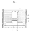
- the aforementioned molded body is, as shown in FIG. 2 , incorporated into the electric spark machine as its electrode 1.
- a processing bath 3 of the electric spark machine is filled with proper oil 5 such as mineral oil and the electrode 1 along with a subject body 7 is sunk into the oil 5.
- the electrode 1 is next brought close to the subject body 7 and electric power is intermittently applied from an external power source to generate electric discharge therebetween, thereby executing electric surface treatment.
- a profile of current and voltage applied from the external power source is exemplarily shown in FIG. 5 for example.
- Voltage V with a voltage value u i is initially applied, however, electric discharge does not occur for a very short duration of time t d and therefore the current I is then 0.
- the voltage V steeply declines down to a voltage value U e and then current I with a steeply increased current value I s flows.
- current I with a steady current value I e flows and then the electric discharge continues for a duration of time t e . Impression of the electric power is suspended for a duration of time t i under proper control and next the same procedures are repeated, thereby realizing intermittent electric discharge.
- t e is 8 microseconds and t i is 64 microseconds for example, but it is not limiting. Further it can be selected that I s is 30 A, I e is less than 10 A and the voltage is in the range of several tens V for example, but it is not limiting.
- the aforementioned discharge surface treatment is applicable to growth of a titanium carbide coating 9 on an end portion 37a of a turbine rotor blade 37 shown in FIG. 6 for example.
- the turbine rotor blades 37 rotate with making severe friction with a turbine shroud which surrounds the blades.
- a hard coating such as titanium carbide is required and also the coating require considerable thickness for proving long-time use. Therefore the present embodiment is preferably applied thereto.
- FIG. 7 schematically depicts a microstructure of the coating 9 according to the present embodiment.
- the coating 9 has a structure in which a metal phase 9m acts as a matrix and titanium carbide phases 9h disperse therein.
- the metal phase 9m gives deformability to the coating, the growing coating stands local thermal shock which may occur in the course of discharge surface treatment, thereby enabling growth of a relatively thick coating.
- the titanium carbide phase 9h gives hardness to the coating, the coating 9 stands long-time operation.
- Table 1 Results of discharge surface treatment with titanium hydride electrodes to which aluminum powder is added Mixing ratio of aluminum powder (mass %) 1 5 10 15 18 20 thickness (micrometers) 30 60 230 200 70 25 micro-Vickers hardness (Hv) 1300 or greater 1300 or greater 1300 or greater 1300 or greater 1300 or greater 1300 or greater 1300 or greater 1300 or greater
- a method for forming thicker coatings including titanium carbide by discharge surface treatment and electrodes therefor are provided.
Landscapes
- Chemical & Material Sciences (AREA)
- Engineering & Computer Science (AREA)
- Materials Engineering (AREA)
- Mechanical Engineering (AREA)
- Metallurgy (AREA)
- Organic Chemistry (AREA)
- Chemical Kinetics & Catalysis (AREA)
- Other Surface Treatments For Metallic Materials (AREA)
- Powder Metallurgy (AREA)
Abstract
Description
- The present invention relates to an electrode for forming a coating on a subject body by using electric discharge, a production method therefor, and a method for forming a coating therewith.
- To bring a non-exhaustible electrode close to a subject body in oil or in the air and then generate electric discharge therebetween may result in machining of the subject body. This art is generally referred to as electric spark machining, which enables precise and complex machining. Under considerable conditions, e.g. a condition in which an exhaustible electrode such as a green pellet is used instead of a non-exhaustible electrode, wear of the electrode preferentially occurs instead of machining of the subject body. Constituents of the electrode or its reaction products then cover a region opposed to the electrode on the subject body, thereby enabling surface treatment of the subject body. This art is sometimes referred to as "discharge surface treatment".
- When the discharge surface treatment is executed in a liquid including hydrocarbon such as mineral oil, substances discharged out of an electrode and carbon often develop chemical reactions, thereby enabling formation of a coating consisting of carbides. Among many carbides, titanium carbide is very hard. Thus such coatings are promising in view of various industrial uses. A related art is disclosed in an International Patent Publication
WO01/005545 - It is possible to successfully form a coating of titanium carbide about 20 - 30 micrometers thick by means of discharge surface treatment. The present inventors had tried growth of a thicker titanium carbide coating in order to seek further improvement of properties and then found that formation of a titanium carbide coating with a thickness greater than the aforementioned thickness is difficult. The present invention has been achieved in view of this problem and is intended to provide a method for forming thicker coatings including titanium carbide by discharge surface treatment and electrodes therefor.
- According to a first aspect of the present invention, an electrode used in combination with an electric spark machine for surface treatment is comprised of a mixed powder including a powder of aluminum at a ratio of 5 - 18 weight % to the total of the mixed powder or a powder of any metal selected from the group consisting of nickel, cobalt, and iron at a ratio of 5 - 40 weight % to the total of the mixed powder, and a powder of titanium hydride, wherein the mixed powder is formed by molding and sintering into a structure so dimensioned as to be incorporated in the electric spark machine as an electrode therefor.
- According to a second aspect of the present invention, a method of production of an electrode used in combination with an electric spark machine, is obtaining a mixed powder by mixing a powder of aluminum at a ratio of 5 - 18 weight % to the total of the mixed powder or a powder of any metal selected from the group consisting of nickel, cobalt, and iron at a ratio of 5 - 40 weight % to the total of the mixed powder with a powder of titanium hydride; and molding and sintering the mixed powder to form a structure so dimensioned as to be incorporated in the electric spark machine as an electrode therefor.
- According to a third aspect of the present invention, a method of surface treatment of a subject body by an electric spark machine is comprised of obtaining a mixed powder by mixing a powder of aluminum at a ratio of 5 - 18 weight % to the total of the mixed powder or a powder of any metal selected from the group consisting of nickel, cobalt, and iron at a ratio of 5 - 40 weight % to the total of the mixed powder with a powder of titanium hydride, obtaining a molded body by molding and sintering the mixed powder to form a structure so dimensioned as to be incorporated in the electric spark machine as an electrode therefor, incorporating the molded body into the electric spark machine, and generating a coating on the subject body by bringing the molded body close to the subject body in an oil and generating electric discharge therebetween.
-
- [
FIG. 1] FIG. 1 is a schematic drawing depicting a microstructure of an electrode according to an embodiment of the present invention. - [
FIG. 2] FIG. 2 is a schematic drawing depicting an electric spark machine used in discharge surface treatment according to the embodiment. - [
FIG. 3] FIG. 3 is a schematic drawing depicting a mixer used in production of the electrode according to the embodiment of the present invention. - [
FIG. 4] FIG. 4 is a schematic drawing depicting a step in the production of the electrode according to the embodiment. - [
FIG. 5] FIG. 5 is an example of a profile of voltage and current applied to the electric spark machine. - [
FIG. 6] FIG. 6 shows an example of a subject body of discharge surface treatment, which depicts an elevational view of a turbine rotor blade. - [
FIG. 7] FIG. 7 is a schematic drawing depicting a microstructure of a coating formed by the discharge surface treatment. - Certain embodiments will be described hereinafter with reference to the appended drawings.
- In discharge surface treatment used is an exhaustible electrode having a property by which it gradually wears in electric discharge. As a material for the exhaustible electrode, a powder including an electrically conductive substance is preferably used. The powder may be totally of any electrically conductive substance, or alternatively be a mixed powder of a powder of an electrically conductive substance and a powder of any other substance, such as a proper ceramic. Further, as the electrically conductive substance, a mixed powder of two or more electrically conductive substances may be used.
- If a titanium hydride (TiH2) is selected as the electrically conductive material and the discharge surface treatment is executed in a liquid including hydrocarbon such as a mineral oil, a coating including titanium carbide is obtained as discussed above. According to studies by the present inventors, when electric discharge is repeatedly applied so as to grow the coating with a thickness beyond 20 - 30 micrometers, it is observed that the growth rate extremely gets smaller. If electric discharge is further repeated, no coating growth is observed. Although the cause of this phenomenon has not been sufficiently made clear, the present inventors currently infer that, when the coating grows to be relatively thick, wearing of the coating occurs as well as it grows and then wearing and growth balance. Thus it can be inferred that, if additives to prevent the coating from wearing are in advance made contained in the electrode, thicker growth of a coating including titanium carbide may be possible.
- Referring to
FIG. 1(a) , in the present embodiment, the electrode is produced by utilizing a mixed powder of apowder 11 of titanium hydride and apowder 13 of aluminum. This titanium hydride, as a result of discharge surface treatment, forms titanium carbide and then becomes incorporated in the coating, thereby giving hardness to the coating. Aluminum, as a result of discharge surface treatment, becomes incorporated in the coating, thereby giving deformability to the coating. In parallel, aluminum changes part of titanium hydride into titanium, which becomes incorporated in the coating, thereby further giving deformability to the coating. A coating with hardness but short of deformability will be vulnerable to local thermal shock given in the process of discharge surface treatment and be therefore likely to wear as it grows. In contrast, a coating with deformability given by aluminum can be resistant to thermal shock and is therefore capable of growing thicker. - The amount of addition of the powder of aluminum is over 0 weight % to the total of the mixed powder because greater amounts lead to better deformability, preferably over 5 weight %, and more preferably over 10 weight %. Moreover, in light of exhaustibility of the electrode after sintering, non-excessive amounts of addition of aluminum are beneficial. Thus the amount is less than 30 weight % to the total of the mixed powder, preferably less than 18 weight %, and more preferably less than 15 weight %.
- Alternatively, instead of the
powder 13 of aluminum, or in addition thereto, apowder 15 of any metal of the iron group may be mixed therein. The metal of the iron group is, in accordance with the well-known definition, any of nickel, cobalt, and iron. Any single element, or a mixture, of nickel, cobalt, and iron may be applicable. These iron group metals, as with aluminum, give deformability to the coating and therefore contribute to thicker growth of the coating. - The amount of addition of the powder of the iron group metal is over 0 weight % to the total of the mixed powder because greater amounts lead to better deformability, preferably over 5 weight %, and more preferably over 10 weight %. Moreover, in light of exhaustibility of the electrode after sintering, non-excessive amounts of addition of the amount of the iron group metal are beneficial. Thus the amount is less than 60 weight % to the total of the mixed powder, preferably less than 40 weight %.
- In addition, a
powder 17 of titanium carbide may be mixed therein as shown inFIG. 1(b) . The powder, if mixed, is preferably over 0 weight % to the total of the mixed powder, and less than 30 weight % in light of retention of sufficient electrical conductivity of the electrode. Inclusion of any component which materially affects the basic and novel characteristics of the present invention is essentially excluded except it is an unavoidable impurity, whereas inclusion of any component which does not materially affect the basic and novel characteristics is permissible. - The particle size may be, although not particularly limited, 10 micrometers or less and more preferably 3 micrometers or less for example.
- The respective powders are mixed together by utilizing any proper mixer.
FIG. 3 depicts an example of such a mixer, which is generally referred to as "V-blender". The V-blender 19 is comprised of a pair of hollow cylinders joined together in a V-letter shape, and is driven by a proper motor to rotate about an axis shown by a dashed line in the drawing. Because the V-blender 19, by means of its rotation, applies force by which the powder in the cylinders departs and force by which the powder gathers together alternately to the powder, and simultaneously stirs the powder, it is preferably suited for uniform mixing. Of course, any other proper mixer can be used. - The
powder 11 of titanium hydride and thepowder 13 of aluminum (alternatively, instead of, or in addition thereto, thepowder 15 of an iron-group metal), and thepowder 17 of titanium carbide added in some cases, are prepared in a way described above and thereafter put in the V-letter-shape cylinder. Then the V-letter-shape cylinder is made to rotate by means of a proper motor, so that the powder is uniformly mixed and then a mixed powder M is obtained. - Preferably the mixed powder M is subject to hot pressing. A hot pressing device is, as shown in
FIG. 4 , comprised of amold 21, which is comprised of a die 27 supporting its side and punches 29, 31 supporting its ends. A space enclosed by thedie 27 and thepunches die 27 and thepunches die 27 is placed in a fixed state, thepunches rams mold 21. The hot pressing device is further comprised of avacuum furnace 33 with aheater 35, and the mixed powder M is heated in a pressurized state, thereby executing molding and sintering simultaneously. A molded body obtained in a step as described above has a structure so dimensioned as to be incorporated in the electric spark machine as its electrode, and is also adapted for electric surface treatment as it has proper exhaustibility. - Instead of hot pressing, hot isostatic pressing (HIP) may be executed. Alternatively, sintering in a vacuum furnace after proper molding may be executed. For the purpose of molding, injection molding or slurry pouring may be used.
- The aforementioned molded body is, as shown in
FIG. 2 , incorporated into the electric spark machine as itselectrode 1. A processing bath 3 of the electric spark machine is filled withproper oil 5 such as mineral oil and theelectrode 1 along with asubject body 7 is sunk into theoil 5. Theelectrode 1 is next brought close to thesubject body 7 and electric power is intermittently applied from an external power source to generate electric discharge therebetween, thereby executing electric surface treatment. - A profile of current and voltage applied from the external power source is exemplarily shown in
FIG. 5 for example. Voltage V with a voltage value ui is initially applied, however, electric discharge does not occur for a very short duration of time td and therefore the current I is then 0. As electric discharge next occurs, the voltage V steeply declines down to a voltage value Ue and then current I with a steeply increased current value Is flows. Subsequently current I with a steady current value Ie flows and then the electric discharge continues for a duration of time te. Impression of the electric power is suspended for a duration of time ti under proper control and next the same procedures are repeated, thereby realizing intermittent electric discharge. It can be selected that te is 8 microseconds and ti is 64 microseconds for example, but it is not limiting. Further it can be selected that Is is 30 A, Ie is less than 10 A and the voltage is in the range of several tens V for example, but it is not limiting. - The aforementioned discharge surface treatment is applicable to growth of a
titanium carbide coating 9 on anend portion 37a of aturbine rotor blade 37 shown inFIG. 6 for example. Theturbine rotor blades 37 rotate with making severe friction with a turbine shroud which surrounds the blades. To protect theturbine rotor blade 37 from the friction, a hard coating such as titanium carbide is required and also the coating require considerable thickness for proving long-time use. Therefore the present embodiment is preferably applied thereto. -
FIG. 7 schematically depicts a microstructure of thecoating 9 according to the present embodiment. Thecoating 9 has a structure in which ametal phase 9m acts as a matrix andtitanium carbide phases 9h disperse therein. As themetal phase 9m gives deformability to the coating, the growing coating stands local thermal shock which may occur in the course of discharge surface treatment, thereby enabling growth of a relatively thick coating. Further as thetitanium carbide phase 9h gives hardness to the coating, thecoating 9 stands long-time operation. - The following tests are executed to demonstrate effects produced by the present embodiment.
- With powder of titanium hydride, 1, 5, 10, 18 and 20 weight % of aluminum powder are respectively mixed, and molding and sintering are executed in a way as described above, thereby obtaining prism-shaped electrodes with a dimension of 4 x 10 mm, respectively. With them respectively and metal mock workpieces in oil, electric discharge is repeatedly generated with a feeding length of 2mm of the electrodes to execute discharge surface treatment. Micro-Vickers hardness measurement is executed on the obtained coatings. Results are summarized in Table 1.
Table 1 Results of discharge surface treatment with titanium hydride electrodes to which aluminum powder is added Mixing ratio of aluminum powder (mass %) 1 5 10 15 18 20 thickness (micrometers) 30 60 230 200 70 25 micro-Vickers hardness (Hv) 1300 or greater 1300 or greater 1300 or greater 1300 or greater 1300 or greater 1300 or greater - As being apparent from Table 1, thicknesses not obtainable by conventional methods (60 micrometers or greater) are obtained if the mixing ratios of the aluminum powder are 5 weight % or greater. Further, in any range, the obtained coatings have hardness of Hv 1300 or greater.
- With powder of titanium hydride, 1, 5, 10, 20, 40 and 50 weight % of nickel powder (nickel carbonyl) are respectively mixed, and molding and sintering are executed in a way as described above, thereby obtaining prism-shaped electrodes with a dimension of 4 x 10 mm, respectively. With them respectively and metal mock workpieces in oil, electric discharge is repeatedly generated with a feeding length of 2mm of the electrodes to execute discharge surface treatment. Micro-Vickers hardness measurement is executed on the obtained coatings. Results are summarized in Table 2.
Table 2 Results of discharge surface treatment with titanium hydride electrodes to which nickel powder is added Mixing ratio of nickel powder (mass %) 1 5 10 20 40 50 thickness (micrometers) 25 55 230 200 250 or greater 250 or greater micro-Vickers hardness (Hv) 1300 or greater 1300 or greater 1300 or greater 1300 or greater 1300 or greater 800 or less - As being apparent from Table 2, thicknesses not obtainable by conventional methods (55 micrometers or greater) are obtained if the mixing ratios of the nickel powder are in any range of 5 weight % or greater. Further, in any range of 40 weight % or less, the obtained coatings have hardness of Hv 1300 or greater.
- With powder of titanium hydride, 1, 5, 10, 20, 40 and 50 weight % of cobalt powder are respectively mixed, and molding and sintering are executed in a way as described above, thereby obtaining prism-shaped electrodes with a dimension of 4 x 10 mm, respectively. With them respectively and metal mock workpieces in oil, electric discharge is repeatedly generated with a feeding length of 2mm of the electrodes to execute discharge surface treatment. Micro-Vickers hardness measurement is executed on the obtained coatings. Results are summarized in Table 3.
Table 3 Results of discharge surface treatment with titanium hydride electrodes to which cobalt powder is added Mixing ratio of cobalt powder (mass %) 1 5 10 20 40 50 thickness (micrometers) 25 45 230 180 200 or greater 200 or greater micro-Vickers hardness (Hv) 1300 or greater 1300 or greater 1300 or greater 1300 or greater 1300 or greater 800 or less - As being apparent from Table 3, thicknesses not obtainable by conventional methods (45 micrometers or greater) are obtained if the mixing ratios of the cobalt powder are in any range of 5 weight % or greater. Further, in any range of 40 weight % or less, the obtained coatings have hardness of Hv 1300 or greater.
- Although detailed data are omitted, similar results are obtained in regard to iron powder as with the nickel powder or the cobalt powder. Further a case where titanium carbide is further added produces similar results.
- More specifically, in the method of surface treatment of a subject body by an electric spark machine, if proper powder of aluminum or any of the iron group is mixed with powder of titanium hydride, resultant mixed powder is molded and sintered and then incorporated in the electric spark machine, and discharge surface treatment is executed in oil, a coating with sufficient thickness and hardness can be obtained. As the thickness and the hardness are sufficient, a long life coating can be expected.
- Although the invention has been described above by reference to certain embodiments of the invention, the invention is not limited to the embodiments described above. Modifications and variations of the embodiments described above will occur to those skilled in the art, in light of the above teachings.
- A method for forming thicker coatings including titanium carbide by discharge surface treatment and electrodes therefor are provided.
Claims (9)
- An electrode used in combination with an electric spark machine for surface treatment, comprising:a mixed powder including a powder of aluminum at a ratio of 5 - 18 weight % to the total of the mixed powder or a powder of any metal selected from the group consisting of nickel, cobalt, and iron at a ratio of 5 - 40 weight % to the total of the mixed powder; anda powder of titanium hydride,wherein the mixed powder is formed by molding and sintering into a structure so dimensioned as to be incorporated in the electric spark machine as an electrode therefor.
- The electrode of claim 1, further comprising:titanium carbide beyond 0 weight % and not greater than 30 weight % to the total of the mixed powder.
- The electrode of claim 2, wherein the powder of the titanium hydride is the rest of the mixed powder.
- A method of production of an electrode used in combination with an electric spark machine, comprising:obtaining a mixed powder by mixing a powder of aluminum at a ratio of 5 - 18 weight % to the total of the mixed powder or a powder of any metal selected from the group consisting of nickel, cobalt, and iron at a ratio of 5 - 40 weight % to the total of the mixed powder with a powder of titanium hydride; andmolding and sintering the mixed powder to form a structure so dimensioned as to be incorporated in the electric spark machine as an electrode therefor.
- The method of claim 4, wherein the mixed powder further includes titanium carbide beyond 0 weight % and not greater than 30 weight % to the total of the mixed powder.
- The method of claim 5, wherein the powder of the titanium hydride is the rest of the mixed powder.
- A method of surface treatment of a subject body by an electric spark machine, comprising:obtaining a mixed powder by mixing a powder of aluminum at a ratio of 5 - 18 weight % to the total of the mixed powder or a powder of any metal selected from the group consisting of nickel, cobalt, and iron at a ratio of 5 - 40 weight % to the total of the mixed powder with a powder of titanium hydride;obtaining a molded body by molding and sintering the mixed powder to form a structure so dimensioned as to be incorporated in the electric spark machine as an electrode therefor;incorporating the molded body into the electric spark machine; andgenerating a coating on the subject body by bringing the molded body close to the subject body in an oil and generating electric discharge therebetween.
- The method of claim 7, wherein the mixed powder further includes titanium carbide beyond 0 weight % and not greater than 30 weight % to the total of the mixed powder.
- The method of claim 8, wherein the powder of the titanium hydride is the rest of the mixed powder.
Applications Claiming Priority (2)
| Application Number | Priority Date | Filing Date | Title |
|---|---|---|---|
| JP2009203629 | 2009-09-03 | ||
| PCT/JP2010/065026 WO2011027825A1 (en) | 2009-09-03 | 2010-09-02 | Electric discharge surface treatment |
Publications (3)
| Publication Number | Publication Date |
|---|---|
| EP2474646A1 true EP2474646A1 (en) | 2012-07-11 |
| EP2474646A4 EP2474646A4 (en) | 2013-11-06 |
| EP2474646B1 EP2474646B1 (en) | 2015-03-04 |
Family
ID=43649359
Family Applications (1)
| Application Number | Title | Priority Date | Filing Date |
|---|---|---|---|
| EP10813773.8A Active EP2474646B1 (en) | 2009-09-03 | 2010-09-02 | Electric discharge surface treatment |
Country Status (4)
| Country | Link |
|---|---|
| US (1) | US20120156394A1 (en) |
| EP (1) | EP2474646B1 (en) |
| JP (1) | JPWO2011027825A1 (en) |
| WO (1) | WO2011027825A1 (en) |
Family Cites Families (10)
| Publication number | Priority date | Publication date | Assignee | Title |
|---|---|---|---|---|
| IT1173866B (en) * | 1984-03-16 | 1987-06-24 | Getters Spa | PERFECT METHOD FOR MANUFACTURING NON-VARIABLE PORTABLE GETTER DEVICES AND GETTER DEVICES SO PRODUCED |
| JP3537939B2 (en) * | 1996-01-17 | 2004-06-14 | 独立行政法人 科学技術振興機構 | Surface treatment by submerged discharge |
| US5858479A (en) * | 1996-01-17 | 1999-01-12 | Japan Science And Technology Corporation | Surface treating method by electric discharge |
| JP3596272B2 (en) * | 1998-02-16 | 2004-12-02 | 三菱電機株式会社 | Discharge surface treatment apparatus and discharge surface treatment method using the same |
| JP3421321B2 (en) * | 1998-03-11 | 2003-06-30 | 三菱電機株式会社 | Green compact electrode for discharge surface treatment and method for manufacturing compact green electrode for discharge surface treatment |
| DE19983550B4 (en) * | 1999-07-16 | 2009-07-09 | Mitsubishi Denki K.K. | Electrode for a spark discharge coating and manufacturing method therefor |
| US6935917B1 (en) * | 1999-07-16 | 2005-08-30 | Mitsubishi Denki Kabushiki Kaisha | Discharge surface treating electrode and production method thereof |
| CN100529182C (en) * | 2002-07-30 | 2009-08-19 | 三菱电机株式会社 | Electrode for electric discharge surface treatment, electric discharge surface treatment method and electric discharge surface treatment apparatus |
| CN1798871B (en) * | 2003-05-29 | 2011-08-10 | 三菱电机株式会社 | Electrode for electric discharge surface treatment, and method and apparatus for electric discharge surface treatment |
| EP1643007B1 (en) * | 2003-05-29 | 2014-01-15 | Mitsubishi Denki Kabushiki Kaisha | Discharge surface treatment electrode and process for its manufacture |
-
2010
- 2010-09-02 EP EP10813773.8A patent/EP2474646B1/en active Active
- 2010-09-02 US US13/392,326 patent/US20120156394A1/en not_active Abandoned
- 2010-09-02 JP JP2011529938A patent/JPWO2011027825A1/en active Pending
- 2010-09-02 WO PCT/JP2010/065026 patent/WO2011027825A1/en not_active Ceased
Also Published As
| Publication number | Publication date |
|---|---|
| JPWO2011027825A1 (en) | 2013-02-04 |
| EP2474646B1 (en) | 2015-03-04 |
| US20120156394A1 (en) | 2012-06-21 |
| EP2474646A4 (en) | 2013-11-06 |
| WO2011027825A1 (en) | 2011-03-10 |
Similar Documents
| Publication | Publication Date | Title |
|---|---|---|
| JP4137886B2 (en) | Discharge surface treatment electrode, discharge surface treatment method, and discharge surface treatment apparatus | |
| CN1185366C (en) | Electrode for discharge surface treatment and manufacturing method, discharge surface treatment method and equipment | |
| CN108558398B (en) | A method of pulse discharge room temperature flash sintering nano-ceramic materials | |
| KR20000057987A (en) | Method of electric sintering method and mold for use in the method | |
| EP1640476B1 (en) | Discharge surface treating electrode, discharge surface treating device and discharge surface treating method | |
| CN109804104B (en) | Sliding member provided with wear-resistant film and method for forming wear-resistant film | |
| CN110229986B (en) | Rare earth tungsten-molybdenum alloy for electrode and preparation method thereof | |
| EP2017370B1 (en) | Coating and method of forming coating | |
| EP2474646B1 (en) | Electric discharge surface treatment | |
| CN102858481B (en) | Method for manufacturing electrode suitable for discharge surface treatment | |
| JP5168288B2 (en) | Discharge surface treatment method and discharge surface treatment coating block | |
| JP2019123638A (en) | Sintering mold and its production method | |
| CN100497736C (en) | Discharging surface processing method and discharge surface processing device | |
| JP6654169B2 (en) | How to make a mold for sintering | |
| JP5408349B2 (en) | Discharge surface treatment electrode and discharge surface treatment film | |
| CN113526959B (en) | Method and device for rapidly sintering tungsten carbide powder without adhesive | |
| JP4504691B2 (en) | Turbine parts and gas turbines | |
| JP3857625B2 (en) | Discharge surface treatment electrode and discharge surface treatment method | |
| RU74844U1 (en) | ELECTRODE FOR ELECTRIC SPARK ALLOYING | |
| JP2012122133A (en) | Method for producing screw and screw | |
| JP4119461B2 (en) | Manufacturing method of electrode for discharge surface treatment | |
| RU76594U1 (en) | ELECTRODE FOR ELECTRIC SPARK ALLOYING | |
| JP4984015B1 (en) | Discharge surface treatment electrode and method for producing discharge surface treatment electrode | |
| JP6615446B2 (en) | Graphite-copper composite electrode material for electric discharge machining and electrode for electric discharge machining using the material | |
| JPWO2006057053A1 (en) | Discharge surface treatment electrode, discharge surface treatment method, and discharge surface treatment apparatus |
Legal Events
| Date | Code | Title | Description |
|---|---|---|---|
| PUAI | Public reference made under article 153(3) epc to a published international application that has entered the european phase |
Free format text: ORIGINAL CODE: 0009012 |
|
| 17P | Request for examination filed |
Effective date: 20120302 |
|
| AK | Designated contracting states |
Kind code of ref document: A1 Designated state(s): AL AT BE BG CH CY CZ DE DK EE ES FI FR GB GR HR HU IE IS IT LI LT LU LV MC MK MT NL NO PL PT RO SE SI SK SM TR |
|
| DAX | Request for extension of the european patent (deleted) | ||
| REG | Reference to a national code |
Ref country code: DE Ref legal event code: R079 Ref document number: 602010022920 Country of ref document: DE Free format text: PREVIOUS MAIN CLASS: C23C0026000000 Ipc: C22C0001050000 |
|
| A4 | Supplementary search report drawn up and despatched |
Effective date: 20131004 |
|
| RIC1 | Information provided on ipc code assigned before grant |
Ipc: C23C 14/02 20060101ALI20130927BHEP Ipc: C22C 1/05 20060101AFI20130927BHEP Ipc: B22F 9/04 20060101ALI20130927BHEP Ipc: B23H 1/06 20060101ALI20130927BHEP Ipc: B23H 9/00 20060101ALI20130927BHEP Ipc: C23C 26/00 20060101ALI20130927BHEP Ipc: B22F 5/00 20060101ALI20130927BHEP |
|
| 17Q | First examination report despatched |
Effective date: 20140425 |
|
| GRAP | Despatch of communication of intention to grant a patent |
Free format text: ORIGINAL CODE: EPIDOSNIGR1 |
|
| INTG | Intention to grant announced |
Effective date: 20141028 |
|
| GRAS | Grant fee paid |
Free format text: ORIGINAL CODE: EPIDOSNIGR3 |
|
| GRAA | (expected) grant |
Free format text: ORIGINAL CODE: 0009210 |
|
| AK | Designated contracting states |
Kind code of ref document: B1 Designated state(s): AL AT BE BG CH CY CZ DE DK EE ES FI FR GB GR HR HU IE IS IT LI LT LU LV MC MK MT NL NO PL PT RO SE SI SK SM TR |
|
| REG | Reference to a national code |
Ref country code: GB Ref legal event code: FG4D |
|
| REG | Reference to a national code |
Ref country code: CH Ref legal event code: EP |
|
| REG | Reference to a national code |
Ref country code: IE Ref legal event code: FG4D |
|
| REG | Reference to a national code |
Ref country code: AT Ref legal event code: REF Ref document number: 713977 Country of ref document: AT Kind code of ref document: T Effective date: 20150415 |
|
| REG | Reference to a national code |
Ref country code: DE Ref legal event code: R096 Ref document number: 602010022920 Country of ref document: DE Effective date: 20150416 |
|
| REG | Reference to a national code |
Ref country code: AT Ref legal event code: MK05 Ref document number: 713977 Country of ref document: AT Kind code of ref document: T Effective date: 20150304 Ref country code: NL Ref legal event code: VDEP Effective date: 20150304 |
|
| PG25 | Lapsed in a contracting state [announced via postgrant information from national office to epo] |
Ref country code: HR Free format text: LAPSE BECAUSE OF FAILURE TO SUBMIT A TRANSLATION OF THE DESCRIPTION OR TO PAY THE FEE WITHIN THE PRESCRIBED TIME-LIMIT Effective date: 20150304 Ref country code: NO Free format text: LAPSE BECAUSE OF FAILURE TO SUBMIT A TRANSLATION OF THE DESCRIPTION OR TO PAY THE FEE WITHIN THE PRESCRIBED TIME-LIMIT Effective date: 20150604 Ref country code: SE Free format text: LAPSE BECAUSE OF FAILURE TO SUBMIT A TRANSLATION OF THE DESCRIPTION OR TO PAY THE FEE WITHIN THE PRESCRIBED TIME-LIMIT Effective date: 20150304 Ref country code: LT Free format text: LAPSE BECAUSE OF FAILURE TO SUBMIT A TRANSLATION OF THE DESCRIPTION OR TO PAY THE FEE WITHIN THE PRESCRIBED TIME-LIMIT Effective date: 20150304 Ref country code: FI Free format text: LAPSE BECAUSE OF FAILURE TO SUBMIT A TRANSLATION OF THE DESCRIPTION OR TO PAY THE FEE WITHIN THE PRESCRIBED TIME-LIMIT Effective date: 20150304 Ref country code: ES Free format text: LAPSE BECAUSE OF FAILURE TO SUBMIT A TRANSLATION OF THE DESCRIPTION OR TO PAY THE FEE WITHIN THE PRESCRIBED TIME-LIMIT Effective date: 20150304 |
|
| REG | Reference to a national code |
Ref country code: LT Ref legal event code: MG4D |
|
| PG25 | Lapsed in a contracting state [announced via postgrant information from national office to epo] |
Ref country code: LV Free format text: LAPSE BECAUSE OF FAILURE TO SUBMIT A TRANSLATION OF THE DESCRIPTION OR TO PAY THE FEE WITHIN THE PRESCRIBED TIME-LIMIT Effective date: 20150304 Ref country code: GR Free format text: LAPSE BECAUSE OF FAILURE TO SUBMIT A TRANSLATION OF THE DESCRIPTION OR TO PAY THE FEE WITHIN THE PRESCRIBED TIME-LIMIT Effective date: 20150605 Ref country code: AT Free format text: LAPSE BECAUSE OF FAILURE TO SUBMIT A TRANSLATION OF THE DESCRIPTION OR TO PAY THE FEE WITHIN THE PRESCRIBED TIME-LIMIT Effective date: 20150304 |
|
| PG25 | Lapsed in a contracting state [announced via postgrant information from national office to epo] |
Ref country code: NL Free format text: LAPSE BECAUSE OF FAILURE TO SUBMIT A TRANSLATION OF THE DESCRIPTION OR TO PAY THE FEE WITHIN THE PRESCRIBED TIME-LIMIT Effective date: 20150304 |
|
| PG25 | Lapsed in a contracting state [announced via postgrant information from national office to epo] |
Ref country code: RO Free format text: LAPSE BECAUSE OF FAILURE TO SUBMIT A TRANSLATION OF THE DESCRIPTION OR TO PAY THE FEE WITHIN THE PRESCRIBED TIME-LIMIT Effective date: 20150304 Ref country code: EE Free format text: LAPSE BECAUSE OF FAILURE TO SUBMIT A TRANSLATION OF THE DESCRIPTION OR TO PAY THE FEE WITHIN THE PRESCRIBED TIME-LIMIT Effective date: 20150304 Ref country code: SK Free format text: LAPSE BECAUSE OF FAILURE TO SUBMIT A TRANSLATION OF THE DESCRIPTION OR TO PAY THE FEE WITHIN THE PRESCRIBED TIME-LIMIT Effective date: 20150304 Ref country code: CZ Free format text: LAPSE BECAUSE OF FAILURE TO SUBMIT A TRANSLATION OF THE DESCRIPTION OR TO PAY THE FEE WITHIN THE PRESCRIBED TIME-LIMIT Effective date: 20150304 Ref country code: PT Free format text: LAPSE BECAUSE OF FAILURE TO SUBMIT A TRANSLATION OF THE DESCRIPTION OR TO PAY THE FEE WITHIN THE PRESCRIBED TIME-LIMIT Effective date: 20150706 |
|
| PG25 | Lapsed in a contracting state [announced via postgrant information from national office to epo] |
Ref country code: PL Free format text: LAPSE BECAUSE OF FAILURE TO SUBMIT A TRANSLATION OF THE DESCRIPTION OR TO PAY THE FEE WITHIN THE PRESCRIBED TIME-LIMIT Effective date: 20150304 Ref country code: IS Free format text: LAPSE BECAUSE OF FAILURE TO SUBMIT A TRANSLATION OF THE DESCRIPTION OR TO PAY THE FEE WITHIN THE PRESCRIBED TIME-LIMIT Effective date: 20150704 |
|
| REG | Reference to a national code |
Ref country code: DE Ref legal event code: R097 Ref document number: 602010022920 Country of ref document: DE |
|
| PG25 | Lapsed in a contracting state [announced via postgrant information from national office to epo] |
Ref country code: IT Free format text: LAPSE BECAUSE OF FAILURE TO SUBMIT A TRANSLATION OF THE DESCRIPTION OR TO PAY THE FEE WITHIN THE PRESCRIBED TIME-LIMIT Effective date: 20150304 |
|
| PLBE | No opposition filed within time limit |
Free format text: ORIGINAL CODE: 0009261 |
|
| STAA | Information on the status of an ep patent application or granted ep patent |
Free format text: STATUS: NO OPPOSITION FILED WITHIN TIME LIMIT |
|
| PG25 | Lapsed in a contracting state [announced via postgrant information from national office to epo] |
Ref country code: DK Free format text: LAPSE BECAUSE OF FAILURE TO SUBMIT A TRANSLATION OF THE DESCRIPTION OR TO PAY THE FEE WITHIN THE PRESCRIBED TIME-LIMIT Effective date: 20150304 |
|
| 26N | No opposition filed |
Effective date: 20151207 |
|
| PG25 | Lapsed in a contracting state [announced via postgrant information from national office to epo] |
Ref country code: SI Free format text: LAPSE BECAUSE OF FAILURE TO SUBMIT A TRANSLATION OF THE DESCRIPTION OR TO PAY THE FEE WITHIN THE PRESCRIBED TIME-LIMIT Effective date: 20150304 |
|
| PG25 | Lapsed in a contracting state [announced via postgrant information from national office to epo] |
Ref country code: MC Free format text: LAPSE BECAUSE OF FAILURE TO SUBMIT A TRANSLATION OF THE DESCRIPTION OR TO PAY THE FEE WITHIN THE PRESCRIBED TIME-LIMIT Effective date: 20150304 Ref country code: LU Free format text: LAPSE BECAUSE OF FAILURE TO SUBMIT A TRANSLATION OF THE DESCRIPTION OR TO PAY THE FEE WITHIN THE PRESCRIBED TIME-LIMIT Effective date: 20150902 |
|
| REG | Reference to a national code |
Ref country code: CH Ref legal event code: PL |
|
| REG | Reference to a national code |
Ref country code: IE Ref legal event code: MM4A |
|
| PG25 | Lapsed in a contracting state [announced via postgrant information from national office to epo] |
Ref country code: IE Free format text: LAPSE BECAUSE OF NON-PAYMENT OF DUE FEES Effective date: 20150902 Ref country code: CH Free format text: LAPSE BECAUSE OF NON-PAYMENT OF DUE FEES Effective date: 20150930 Ref country code: LI Free format text: LAPSE BECAUSE OF NON-PAYMENT OF DUE FEES Effective date: 20150930 |
|
| REG | Reference to a national code |
Ref country code: FR Ref legal event code: PLFP Year of fee payment: 7 |
|
| PG25 | Lapsed in a contracting state [announced via postgrant information from national office to epo] |
Ref country code: BE Free format text: LAPSE BECAUSE OF FAILURE TO SUBMIT A TRANSLATION OF THE DESCRIPTION OR TO PAY THE FEE WITHIN THE PRESCRIBED TIME-LIMIT Effective date: 20150304 |
|
| PG25 | Lapsed in a contracting state [announced via postgrant information from national office to epo] |
Ref country code: MT Free format text: LAPSE BECAUSE OF FAILURE TO SUBMIT A TRANSLATION OF THE DESCRIPTION OR TO PAY THE FEE WITHIN THE PRESCRIBED TIME-LIMIT Effective date: 20150304 |
|
| PG25 | Lapsed in a contracting state [announced via postgrant information from national office to epo] |
Ref country code: BG Free format text: LAPSE BECAUSE OF FAILURE TO SUBMIT A TRANSLATION OF THE DESCRIPTION OR TO PAY THE FEE WITHIN THE PRESCRIBED TIME-LIMIT Effective date: 20150304 Ref country code: HU Free format text: LAPSE BECAUSE OF FAILURE TO SUBMIT A TRANSLATION OF THE DESCRIPTION OR TO PAY THE FEE WITHIN THE PRESCRIBED TIME-LIMIT; INVALID AB INITIO Effective date: 20100902 Ref country code: SM Free format text: LAPSE BECAUSE OF FAILURE TO SUBMIT A TRANSLATION OF THE DESCRIPTION OR TO PAY THE FEE WITHIN THE PRESCRIBED TIME-LIMIT Effective date: 20150304 |
|
| PG25 | Lapsed in a contracting state [announced via postgrant information from national office to epo] |
Ref country code: CY Free format text: LAPSE BECAUSE OF FAILURE TO SUBMIT A TRANSLATION OF THE DESCRIPTION OR TO PAY THE FEE WITHIN THE PRESCRIBED TIME-LIMIT Effective date: 20150304 |
|
| REG | Reference to a national code |
Ref country code: FR Ref legal event code: PLFP Year of fee payment: 8 |
|
| PG25 | Lapsed in a contracting state [announced via postgrant information from national office to epo] |
Ref country code: TR Free format text: LAPSE BECAUSE OF FAILURE TO SUBMIT A TRANSLATION OF THE DESCRIPTION OR TO PAY THE FEE WITHIN THE PRESCRIBED TIME-LIMIT Effective date: 20150304 |
|
| PG25 | Lapsed in a contracting state [announced via postgrant information from national office to epo] |
Ref country code: MK Free format text: LAPSE BECAUSE OF FAILURE TO SUBMIT A TRANSLATION OF THE DESCRIPTION OR TO PAY THE FEE WITHIN THE PRESCRIBED TIME-LIMIT Effective date: 20150304 |
|
| REG | Reference to a national code |
Ref country code: FR Ref legal event code: PLFP Year of fee payment: 9 |
|
| PG25 | Lapsed in a contracting state [announced via postgrant information from national office to epo] |
Ref country code: AL Free format text: LAPSE BECAUSE OF FAILURE TO SUBMIT A TRANSLATION OF THE DESCRIPTION OR TO PAY THE FEE WITHIN THE PRESCRIBED TIME-LIMIT Effective date: 20150304 |
|
| PGFP | Annual fee paid to national office [announced via postgrant information from national office to epo] |
Ref country code: DE Payment date: 20250730 Year of fee payment: 16 |
|
| PGFP | Annual fee paid to national office [announced via postgrant information from national office to epo] |
Ref country code: GB Payment date: 20250731 Year of fee payment: 16 |
|
| PGFP | Annual fee paid to national office [announced via postgrant information from national office to epo] |
Ref country code: FR Payment date: 20250808 Year of fee payment: 16 |