EP2474467A1 - A marine device to record seismic and/or electromagnetic data - Google Patents
A marine device to record seismic and/or electromagnetic data Download PDFInfo
- Publication number
- EP2474467A1 EP2474467A1 EP11305020A EP11305020A EP2474467A1 EP 2474467 A1 EP2474467 A1 EP 2474467A1 EP 11305020 A EP11305020 A EP 11305020A EP 11305020 A EP11305020 A EP 11305020A EP 2474467 A1 EP2474467 A1 EP 2474467A1
- Authority
- EP
- European Patent Office
- Prior art keywords
- submerged
- power source
- anyone
- marine device
- payload
- Prior art date
- Legal status (The legal status is an assumption and is not a legal conclusion. Google has not performed a legal analysis and makes no representation as to the accuracy of the status listed.)
- Granted
Links
Images

Classifications
-
- G—PHYSICS
- G01—MEASURING; TESTING
- G01V—GEOPHYSICS; GRAVITATIONAL MEASUREMENTS; DETECTING MASSES OR OBJECTS; TAGS
- G01V1/00—Seismology; Seismic or acoustic prospecting or detecting
- G01V1/38—Seismology; Seismic or acoustic prospecting or detecting specially adapted for water-covered areas
- G01V1/3817—Positioning of seismic devices
-
- B—PERFORMING OPERATIONS; TRANSPORTING
- B63—SHIPS OR OTHER WATERBORNE VESSELS; RELATED EQUIPMENT
- B63B—SHIPS OR OTHER WATERBORNE VESSELS; EQUIPMENT FOR SHIPPING
- B63B21/00—Tying-up; Shifting, towing, or pushing equipment; Anchoring
- B63B21/56—Towing or pushing equipment
- B63B21/66—Equipment specially adapted for towing underwater objects or vessels, e.g. fairings for tow-cables
-
- Y—GENERAL TAGGING OF NEW TECHNOLOGICAL DEVELOPMENTS; GENERAL TAGGING OF CROSS-SECTIONAL TECHNOLOGIES SPANNING OVER SEVERAL SECTIONS OF THE IPC; TECHNICAL SUBJECTS COVERED BY FORMER USPC CROSS-REFERENCE ART COLLECTIONS [XRACs] AND DIGESTS
- Y02—TECHNOLOGIES OR APPLICATIONS FOR MITIGATION OR ADAPTATION AGAINST CLIMATE CHANGE
- Y02A—TECHNOLOGIES FOR ADAPTATION TO CLIMATE CHANGE
- Y02A90/00—Technologies having an indirect contribution to adaptation to climate change
- Y02A90/30—Assessment of water resources
Definitions
- a submerged payload such as an elongated subsea cable adapted to record seismic and/or electromagnetic data and transfer said data to a processing unit which can be located on a ship.
- Difficulties remain concerning anchoring the submerged payload, maintaining the floating buoy at or near the surface of water, while the buoys are now more and more heavy and large. Their overweights are related at least notably to increase of electrical power requirements. Further, allowing the submerged payload to be precisely located, or localizable, especially in deep water, is important.
- the submerged anchor will include at least a part of said power source submerged part.
- said power source submerged part will possibly be used as dead weight.
- the submerged anchor is connected to the mooring line, retaining the floating buoy and preventing it from drifting will be easier than before.
- At least one of the power source submerged part and the submerged anchor has a mass allowing it to lay down on seabed and the surface floating buoy is mechanically connected therewith.
- the power source includes at least one electrochemical battery cell and said (submerged part) power source is used as dead weight.
- the floating buoy and submerged payload are connected through at least one of a wireless connection and a cable (electrical or optical) connection, collecting data from the payload (such as recorded seismic data or electromagnetic data) and/or allowing the data transmitter to transmit such data will be allowed.
- the submerged payload comprises an elongated subsea cable and said at least one of the second electrical means and electronics comprises at least one of a seismic sensor and an electromagnetic sensor, such a sensitive payload should take advantage of both an improved power source (higher power capacity) and a stabilized buoy offering higher electronics and/or transmission capacities.
- the mooring line be adapted for passing therethrough at least one of electrical, hydraulic and pneumatic powers, data (seismic or electromagnetic data) and fluid.
- data semiconductor or electromagnetic data
- Such a dual (mechanical and other) function mooring line will improve the safety and efficiency of the marine device.
- the mooring line comprises at least one of a cable (electrical or optical)adapted to transmit seismic or electromagnetic data, also called data cable later on description, and an electrical cable adapted to supply the power for said submerged payload.
- a cable electrical or optical
- an electrical cable adapted to supply the power for said submerged payload.
- the mooring line is flexible over at least a major portion of its length, so as to define a common cable line adapted to both electrically and mechanically connect the floating buoy and at least one of the submerged anchor, the submerged payload and the power source submerged part.
- An improved control of the mechanical stress (especially on the buoy) should also be reached.
- the submerged payload is connected to the power source submerged part through at least one of a splitter and a jumper, different ways of connecting the elements will be available.
- the marine device will further comprise at least one mid-water buoy having positive buoyancy and disposed at or connected to an intermediate portion of the mooring line, for allowing it to float under the water surface. This will improve the ability of controlling (limiting) the mechanical stresses, especially those soliciting the floating buoy.
- the submerged anchor will comprise a plurality of submerged anchors located on seabed. A drifting prevention in different directions will thus be reached.
- the submerged anchor will preferably include materials including at least one of:
- the submerged anchor(s) will have at least a dual function: dead weight and power/communication/processing function.
- a marine device 1 including specifications in conformity with the invention and adapted to be disposed in water.
- the marine device 1 comprises a floating buoy 3, a submerged payload 5, a power source 7 at least a part of which, 7a, is submerged, and a mooring line 9 extending between the floating buoy 3 and at least one of the power source submerged part 7a, the submerged payload 5 and a submerged anchor 11; see figure 2 .
- buoy covers any shape of buoy, including for example a platform shape, provided that said platform has a floating capacity.
- the submerged anchor 11 has a mass allowing it to stay under the water surface 13, for preventing the floating buoy from drifting beyond a determined area referenced 130 figures 2 , 6 .
- the floating buoy 3 contains electrical means and electronics 15 including a data logger 15a, a data receiver 15b and a data transmitter 15c (see figure 7 ). Said buoy 3 has a mass allowing it to float at the surface, or near the surface 13 of water (just below).
- the submerged anchor 11 comprises at least one heavy block.
- Figure 6 it comprises a plurality of submerged anchors 110, 111, 113 located on seabed 12. Disposing such a plurality of submerged anchors radially around a vertical axis 3a passing by the floating buoy 3 will prevent it from excessively drifting in different directions more closely.
- the so-called mooring line 9 can be one of the respective cable links 9, 19, 29 which (at least) mechanically connect the buoy 3 to the respective dead weights, or passive anchors, 110, 111, 113.
- cable links 19, 29 are mechanical links, only.
- the submerged payload 5 has also a mass allowing it to stay under the water surface 13. It contains at least one of electrical means and electronics 17a, 17b, such as sensors, data transmitter, switches,... .
- the submerged payload 5 comprises an elongated subsea cable 50.
- said at least one of electrical means and electronics 17a, 17b comprises at least one sensor 170a, like seismic sensor (geophone or hydrophone for example) and a electromagnetic sensor; see figure 3 .
- the latter and said submerged payload 5 are connected through at least one of a wireless connection and a cable (electrical or optical) connection.
- reference 23 shows such a wireless connection.
- cable 50 has a weight allowing it to lay down on seabed 12 over at least the major part of its length.
- the submerged payload comprises an elongated subsea cable 50
- the latter can be a cable of a seismic survey system.
- the sensor unit of such a cable typically includes at least one of a electromagnetic sensor and a seismic sensors, these lasts allowing to detect particle motion waves (geophones) and/or pressure waves (hydrophones).
- a decoupling device can substantially mechanically uncouple the sensor unit from the cable.
- marine cable 50 can be used in a seismic survey conducted by a vessel towing an acoustic source close to a water surface.
- This source emits acoustical energy, typically in the form of pressure waves (p-waves), that penetrates a geological formation of interest below a seabed or mud line (often called "subsurface formation").
- p-waves pressure waves
- subsurface formation of interest below a seabed or mud line
- a network of sensors e.g., hydrophones mounted in one or more cables registers reflected acoustical energy in the form of p-waves. These cables are typically towed in conjunction with or separately from the acoustic source.
- the hydrophones are pressure sensitive electrical sensors that generate electrical signals corresponding to the detected acoustical energy.
- s-waves shear waves
- the sensors configured to detect s-waves are ideally placed at the seabed to record this type of signals. This is known technology, and the method is amongst other described in U.S. Patent No. 4,725,990 .
- the sensors that are used have to be motion sensitive (e.g., geophones or accelerometers).
- FIG 1 shows an exemplary embodiment of a marine seismic survey system 10 for recording seismic or electromagnetic data.
- the preferred system 10 includes a first vessel 2 for towing a seismic source 4 such as an air gun array and a second vessel 6 for deploying cable 50 with sensor units 171 at the seabed 12.
- the survey can be performed with one vessel.
- a vessel can deploy the sensor cable 50, which can include tethering or hooking up the sensor cable 50 to a substantially stationary installation, which can be buoy 3, in a pre-selected area.
- substantially stationary it is meant that the movement of the sensor is restricted to a predefined range or perimeter.
- the buoy can be fitted with a suitable data recording system 15d ( figure 7 ). Thereafter, the same vessel can deploy the seismic source.
- the cable-deployment vessel and the source-towing vessel are the same vessel.
- the seismic source 4 upon deployment, emits acoustic pulses or pressure waves ("p-waves"), illustrated by line 8, that propagate through the water and the different layers of a subsurface geological formation of interest 14.
- p-waves acoustic pulses or pressure waves
- Some of the energy in the emitted energy 8 is reflected from the boundaries between the different layers in the subsurface formation 16. These boundaries are sometimes referred to as "reflectors” having different acoustic impedances.
- the reflected acoustical energy will partly be shear waves ("s-waves") and partly p-waves, and are illustrated by line 18.
- the reflected energy is detected by the sensor units 171, which transmit responsive signals to a recording system (not shown) onboard the vessel 6. These signals are recorded, processed and analyzed by known techniques.
- Vessel or ship 6 can accordingly be provided with a processing unit 33 and a communication unit 35 ( figure 1 ) for recovering data from the payload (such as seismic data), possibly through the data transmitter 15c, the data receiver 15b, and the data logger 15a, via antenna 15e of the buoy 3.
- a processing unit 33 and a communication unit 35 figure 1 for recovering data from the payload (such as seismic data), possibly through the data transmitter 15c, the data receiver 15b, and the data logger 15a, via antenna 15e of the buoy 3.
- the submerged anchor 11 can be, or include, one or more heavy dead weight, such as a block of concrete. However, it is recommended that the submerged anchor 11 includes materials including at least one of:
- Electrical means 110a can be switches, pumps, generator; electronics 110b can be loggers, data memories, communication unit for communication with buoy 3,... .
- such means will include an electric power unit (referenced 27 below), electronics and communication means which can be used to power and communicate with buoy 3, and possibly any other subsea system connected to the submerged anchor 11.
- an electric power unit referenced 27 below
- electronics and communication means which can be used to power and communicate with buoy 3, and possibly any other subsea system connected to the submerged anchor 11.
- the following components could be housed in buoy 3: Wireless communication means (HF radio, Wifi, etc..), Wired communication means (Ethernet, USB, FireWire IEEE1394, or any other protocol), optical or electrical communication means for data communication, light power supplies or conversion systems, data logger, computer or microcontroller.
- Wireless communication means HF radio, Wifi, etc..
- Wired communication means Ethernet, USB, FireWire IEEE1394, or any other protocol
- optical or electrical communication means for data communication light power supplies or conversion systems
- data logger computer or microcontroller.
- the submerged payload 5 and the submerged power source 7a be connected.
- the submerged power source 7a could also be used for powering the active components of electrical means and electronics 15 of the buoy 3, while being involved in the anti-drifting action.
- both the power source submerged part and the submerged anchor 11 will preferably have a mass allowing them to lay on seabed 12, for preventing drifting of the buoy 3, as explained.
- the electrical power source submerged part 7a is electrically connected to the submerged payload 5 and the floating buoy 3.
- Such a connection can be direct or indirect.
- the power source will include one or more electrical battery 27.
- Figure 2 shows, as elements of part 7a, a lead-acid battery cell 27a and a fuel cell 27b which are both electrochemical batteries. Only one of them can be used.
- the mooring line 9 extends between the floating buoy 5 and at least one of the power source submerged part 7a, the submerged payload 5 and the submerged anchor 11.
- the mooring line 9 will be connected at one end to the floating buoy 3 and, at the opposite end, to the submerged anchor 11.
- the length of the mooring line 9 is referenced L
- said mooring line comprises a cable 90, also called “data cable”, adapted to transmit seismic or electromagnetic data through electrical or optical connection, and an electrical cable 91 for supplying electrical power to the submerged payload (for example, in a preferred embodiment).
- the mooring line will preferably be flexible over at least a major portion of its length L , so as to define a common cable line adapted to both electrically and mechanically connect the floating buoy 3 and the submerged anchor 11, the submerged payload 5 and the power source submerged part 7a, directly or not.
- Figure 9 shows a mooring line 900 adapted for passing therethrough electrical power, through cable 910, hydraulic power, through duct 911, pneumatic power, through duct 912, seismic or electromagnetic data, through cable 913, and fluid (such as water), through duct 914.
- the figure 3 shows said submerged payload 5 connected to the power source submerged part 7a through the splitter 25.
- the figure 4 shows said submerged payload 5 connected to the power source submerged part 7a through the jumper 27.
- FIGS 3-5 show embodiments in which the marine device 1 further comprises at least one mid-water buoy 300, 301 (presently, a plurality) having positive buoyancy and disposed at (buoys 300), or connected to (buoys 301), an intermediate portion of the mooring line 9, for allowing it to float under the water surface 13.
- the marine device 1 further comprises at least one mid-water buoy 300, 301 (presently, a plurality) having positive buoyancy and disposed at (buoys 300), or connected to (buoys 301), an intermediate portion of the mooring line 9, for allowing it to float under the water surface 13.
- the payload is also a mid-water component.
- the mooring line has an S-shape, lazy wave, steep wave or lazy S configuration. Consequently, it has a reserve of length adapted for absorbing limited movements and primary stress. Such an over-length prevents the buoy 3 from being excessively stresses via line 9. Other shapes can be retained.
Landscapes
- Life Sciences & Earth Sciences (AREA)
- Engineering & Computer Science (AREA)
- Physics & Mathematics (AREA)
- General Life Sciences & Earth Sciences (AREA)
- Geophysics (AREA)
- Environmental & Geological Engineering (AREA)
- Geology (AREA)
- Remote Sensing (AREA)
- Oceanography (AREA)
- General Physics & Mathematics (AREA)
- Acoustics & Sound (AREA)
- Chemical & Material Sciences (AREA)
- Combustion & Propulsion (AREA)
- Mechanical Engineering (AREA)
- Ocean & Marine Engineering (AREA)
- Laying Of Electric Cables Or Lines Outside (AREA)
- Other Liquid Machine Or Engine Such As Wave Power Use (AREA)
- Arrangements For Transmission Of Measured Signals (AREA)
Abstract
Description
- Is concerned a marine device adapted for cooperating with a submerged payload, such as an elongated subsea cable adapted to record seismic and/or electromagnetic data and transfer said data to a processing unit which can be located on a ship.
- Should be already known such a marine device comprising:
- a floating buoy having a mass allowing it to float at the surface or near the surface of water and containing electronics including at least one of first electrical means and electronics,
- a submerged payload at least a part of which has a mass allowing it to stay under the water surface and containing at least one of second electrical means and electronics.
- a power source, and
- a mooring line.
- Difficulties remain concerning anchoring the submerged payload, maintaining the floating buoy at or near the surface of water, while the buoys are now more and more heavy and large. Their overweights are related at least notably to increase of electrical power requirements. Further, allowing the submerged payload to be precisely located, or localizable, especially in deep water, is important.
- For overcoming at least some of the above drawbacks, it is presently recommended that:
- at least a part of the power source is submerged and electrically connected to at least one of the submerged payload and the floating buoy and,
- the mooring line extends between the surface floating buoy and at least one of the power source submerged part, the submerged payload and a submerged anchor having a mass allowing it to stay under the water surface, for preventing the floating buoy from drifting beyond a determined area.
- Preferably, the submerged anchor will include at least a part of said power source submerged part. As a consequence, said power source submerged part will possibly be used as dead weight.
- If, as recommended, the submerged anchor is connected to the mooring line, retaining the floating buoy and preventing it from drifting will be easier than before.
- Same effect if at least one of the power source submerged part and the submerged anchor has a mass allowing it to lay down on seabed and the surface floating buoy is mechanically connected therewith.
- Same effect if the power source includes at least one electrochemical battery cell and said (submerged part) power source is used as dead weight.
- If the floating buoy and submerged payload are connected through at least one of a wireless connection and a cable (electrical or optical) connection, collecting data from the payload (such as recorded seismic data or electromagnetic data) and/or allowing the data transmitter to transmit such data will be allowed.
- If the submerged payload comprises an elongated subsea cable and said at least one of the second electrical means and electronics comprises at least one of a seismic sensor and an electromagnetic sensor, such a sensitive payload should take advantage of both an improved power source (higher power capacity) and a stabilized buoy offering higher electronics and/or transmission capacities.
- According to another aspect, it is recommended that the mooring line be adapted for passing therethrough at least one of electrical, hydraulic and pneumatic powers, data (seismic or electromagnetic data) and fluid. Such a dual (mechanical and other) function mooring line will improve the safety and efficiency of the marine device.
- Such advantages will also be reached if the mooring line comprises at least one of a cable (electrical or optical)adapted to transmit seismic or electromagnetic data, also called data cable later on description, and an electrical cable adapted to supply the power for said submerged payload.
- It is also an advantage if the mooring line is flexible over at least a major portion of its length, so as to define a common cable line adapted to both electrically and mechanically connect the floating buoy and at least one of the submerged anchor, the submerged payload and the power source submerged part. An improved control of the mechanical stress (especially on the buoy) should also be reached.
- If the submerged payload is connected to the power source submerged part through at least one of a splitter and a jumper, different ways of connecting the elements will be available.
- According to a further aspect, the marine device will further comprise at least one mid-water buoy having positive buoyancy and disposed at or connected to an intermediate portion of the mooring line, for allowing it to float under the water surface. This will improve the ability of controlling (limiting) the mechanical stresses, especially those soliciting the floating buoy.
- According to another aspect, the submerged anchor will comprise a plurality of submerged anchors located on seabed. A drifting prevention in different directions will thus be reached.
- According to a further aspect, the submerged anchor will preferably include materials including at least one of:
- said power source submerged part, and
- at least one of (third) electrical means and electronics.
- As a consequence, the submerged anchor(s) will have at least a dual function: dead weight and power/communication/processing function.
- The above-mentioned architecture can present several advantages compared to a more classical one in which active components of the weight are in the surface buoy:
- lighter and smaller buoy,
- possibility to use energy sources that could not be used on a moving/dynamic buoy,
- power sources being heavy elements, their mass is used as part of the dead weight,
- better cooling of power source and at least some electronics in cold subsea water, away from direct sunlight,
- if elements to be powered are subsea the energy source (in the weight) is closer, hence limiting voltage drops and energy losses.
- The following description discloses various details in relation to different embodiments shown in drawings, which are given by way of illustration only, and thus are not limiting the invention, and wherein:
-
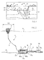
figure 1 schematically illustrates a marine seismic survey system arranged according to one embodiment, -
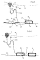
figure 2 schematically illustrates a marine device arranged according to one embodiment, -
figures 3, 4 ,5 schematically illustrate marine devices arranged according to different embodiments, -
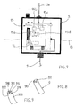
figure 6 schematically illustrates an alternative embodiment for anchoring the buoy, -
figure 7 shows details about the buoy, according to one embodiment, -
figures 8, 9 schematically illustrate a portion of mooring line according to two different embodiments. - Through the figures is detailed a marine device 1 including specifications in conformity with the invention and adapted to be disposed in water.
- The marine device 1 comprises a
floating buoy 3, a submerged payload 5, a power source 7 at least a part of which, 7a, is submerged, and amooring line 9 extending between thefloating buoy 3 and at least one of the power source submergedpart 7a, the submerged payload 5 and a submergedanchor 11; seefigure 2 . - It must be clear that the expression "buoy" covers any shape of buoy, including for example a platform shape, provided that said platform has a floating capacity.
- The submerged
anchor 11 has a mass allowing it to stay under thewater surface 13, for preventing the floating buoy from drifting beyond a determined area referenced 130figures 2 ,6 . - The
floating buoy 3 contains electrical means andelectronics 15 including adata logger 15a, adata receiver 15b and adata transmitter 15c (seefigure 7 ). Saidbuoy 3 has a mass allowing it to float at the surface, or near thesurface 13 of water (just below). - In the illustrations, the submerged
anchor 11 comprises at least one heavy block.Figure 6 , it comprises a plurality of submergedanchors seabed 12. Disposing such a plurality of submerged anchors radially around a vertical axis 3a passing by the floatingbuoy 3 will prevent it from excessively drifting in different directions more closely. As illustratedfigure 6 , the so-calledmooring line 9 can be one of therespective cable links buoy 3 to the respective dead weights, or passive anchors, 110, 111, 113. In the illustration,cable links - The submerged payload 5 has also a mass allowing it to stay under the
water surface 13. It contains at least one of electrical means andelectronics 17a, 17b, such as sensors, data transmitter, switches,... . Specifically, in the illustrated embodiment, the submerged payload 5 comprises anelongated subsea cable 50. And said at least one of electrical means andelectronics 17a, 17b comprises at least onesensor 170a, like seismic sensor (geophone or hydrophone for example) and a electromagnetic sensor; seefigure 3 . - To improve the efficiency of the floating
buoy 3, the latter and said submerged payload 5 are connected through at least one of a wireless connection and a cable (electrical or optical) connection. -
Figure 3 ,reference 23 shows such a wireless connection. - In the illustrations,
cable 50 has a weight allowing it to lay down onseabed 12 over at least the major part of its length. - If the submerged payload comprises an
elongated subsea cable 50, the latter can be a cable of a seismic survey system. The sensor unit of such a cable typically includes at least one of a electromagnetic sensor and a seismic sensors, these lasts allowing to detect particle motion waves (geophones) and/or pressure waves (hydrophones). A decoupling device can substantially mechanically uncouple the sensor unit from the cable. - Thus, with such a marine cable having a sensor unit, detection of reflected acoustical energy can be obtained.
- As a consequence,
marine cable 50 can be used in a seismic survey conducted by a vessel towing an acoustic source close to a water surface. This source emits acoustical energy, typically in the form of pressure waves (p-waves), that penetrates a geological formation of interest below a seabed or mud line (often called "subsurface formation"). Some of the emitted energy is reflected when the pressure waves pass through the boundaries between the different layers in the ground. A network of sensors (e.g., hydrophones) mounted in one or more cables registers reflected acoustical energy in the form of p-waves. These cables are typically towed in conjunction with or separately from the acoustic source. Conventionally, the hydrophones are pressure sensitive electrical sensors that generate electrical signals corresponding to the detected acoustical energy. - Parts of the energy in the emitted p-waves are reflected as shear waves (s-waves). By registration of the s-waves one can get additional information about the subsurface formation. S-waves propagate only through solids, not liquids. Therefore, the sensors configured to detect s-waves are ideally placed at the seabed to record this type of signals. This is known technology, and the method is amongst other described in
U.S. Patent No. 4,725,990 . The sensors that are used have to be motion sensitive (e.g., geophones or accelerometers). -
Figure 1 shows an exemplary embodiment of a marine seismic survey system 10 for recording seismic or electromagnetic data. The preferred system 10 includes a first vessel 2 for towing a seismic source 4 such as an air gun array and a second vessel 6 for deployingcable 50 withsensor units 171 at theseabed 12. Alternatively, the survey can be performed with one vessel. For example, a vessel can deploy thesensor cable 50, which can include tethering or hooking up thesensor cable 50 to a substantially stationary installation, which can bebuoy 3, in a pre-selected area. By substantially stationary, it is meant that the movement of the sensor is restricted to a predefined range or perimeter. The buoy can be fitted with a suitabledata recording system 15d (figure 7 ). Thereafter, the same vessel can deploy the seismic source. Thus, in such an alternate arrangement, the cable-deployment vessel and the source-towing vessel are the same vessel. - Regardless of the particular arrangement used, and as illustrated
figure 1 , the seismic source 4, upon deployment, emits acoustic pulses or pressure waves ("p-waves"), illustrated byline 8, that propagate through the water and the different layers of a subsurface geological formation ofinterest 14. Some of the energy in the emittedenergy 8 is reflected from the boundaries between the different layers in thesubsurface formation 16. These boundaries are sometimes referred to as "reflectors" having different acoustic impedances. The reflected acoustical energy will partly be shear waves ("s-waves") and partly p-waves, and are illustrated byline 18. The reflected energy is detected by thesensor units 171, which transmit responsive signals to a recording system (not shown) onboard the vessel 6. These signals are recorded, processed and analyzed by known techniques. - The above details are disclosed in
EP-A-1385022 . - Vessel or ship 6 can accordingly be provided with a
processing unit 33 and a communication unit 35 (figure 1 ) for recovering data from the payload (such as seismic data), possibly through thedata transmitter 15c, thedata receiver 15b, and thedata logger 15a, viaantenna 15e of thebuoy 3. - The submerged
anchor 11 can be, or include, one or more heavy dead weight, such as a block of concrete. However, it is recommended that the submergedanchor 11 includes materials including at least one of: - said power source submerged
part 7a, and - at least one of
electrical means 110a and electronics 110b; seefigure 2 . - Electrical means 110a can be switches, pumps, generator; electronics 110b can be loggers, data memories, communication unit for communication with
buoy 3,... . - Preferably, such means will include an electric power unit (referenced 27 below), electronics and communication means which can be used to power and communicate with
buoy 3, and possibly any other subsea system connected to the submergedanchor 11. - Functions of submerged
anchor 11 are included in the following: - providing anchoring function to the
buoy 3, by acting as a dead weight; - providing electric power to the buoy and/or the payload;
- providing communication means if needed, for controlling communications between the various components of the system.
- Functions of the
buoy 3 are included in the following: - providing localisation means for easy recovery with the support vessel 6,2;
- providing communication means between the support vessel and the submerged
anchor 11, for monitoring and/or quality control; - providing communication means by wireless, optical or electrical communication between the
buoy 3 and any subsea equipment as submergedanchor 11 and/or payload 5 (figure 4 depicts, for example, one embodiment with wireless means 23 for communication); - providing localization/recovery means for easy retrieval at the end of the mission or the installation operation of the payload 5;
- embedding any equipments, electronics,... and even possible light energy source (wind turbine and/or solar unit 7b..) that are would not be integrated in
anchor 11. - The following components could be housed in buoy 3: Wireless communication means (HF radio, Wifi, etc..), Wired communication means (Ethernet, USB, FireWire IEEE1394, or any other protocol), optical or electrical communication means for data communication, light power supplies or conversion systems, data logger, computer or microcontroller.
- Basically, it is not necessarily requested that the submerged payload 5 and the submerged
power source 7a be connected. The submergedpower source 7a could also be used for powering the active components of electrical means andelectronics 15 of thebuoy 3, while being involved in the anti-drifting action. - As above-mentioned, another part of the electrical power source, 7b, can be maintained within the
buoy 3; seefigure 7 . It is however a minor part of the global power source 7. - As illustrated
figure 2 , both the power source submerged part and the submergedanchor 11 will preferably have a mass allowing them to lay onseabed 12, for preventing drifting of thebuoy 3, as explained. - For providing at least a part of the electrical power to the device, the electrical power source submerged
part 7a is electrically connected to the submerged payload 5 and the floatingbuoy 3. - Such a connection can be direct or indirect.
- Advantageously, the power source will include one or more
electrical battery 27. -
Figure 2 shows, as elements ofpart 7a, a lead-acid battery cell 27a and a fuel cell 27b which are both electrochemical batteries. Only one of them can be used. - For the previously cited mechanical and/or communication and/or electrical requirements (and possibly others), the
mooring line 9 extends between the floating buoy 5 and at least one of the power source submergedpart 7a, the submerged payload 5 and the submergedanchor 11. - Preferably, the
mooring line 9 will be connected at one end to the floatingbuoy 3 and, at the opposite end, to the submergedanchor 11. - According to
figures 6 and8 , the length of themooring line 9 is referenced L, and said mooring line comprises acable 90, also called "data cable", adapted to transmit seismic or electromagnetic data through electrical or optical connection, and anelectrical cable 91 for supplying electrical power to the submerged payload (for example, in a preferred embodiment). - The mooring line will preferably be flexible over at least a major portion of its length L, so as to define a common cable line adapted to both electrically and mechanically connect the floating
buoy 3 and the submergedanchor 11, the submerged payload 5 and the power source submergedpart 7a, directly or not. -
Figure 9 shows amooring line 900 adapted for passing therethrough electrical power, throughcable 910, hydraulic power, throughduct 911, pneumatic power, throughduct 912, seismic or electromagnetic data, throughcable 913, and fluid (such as water), throughduct 914. - The
figure 3 shows said submerged payload 5 connected to the power source submergedpart 7a through thesplitter 25. - The
figure 4 shows said submerged payload 5 connected to the power source submergedpart 7a through thejumper 27. - Further,
figures 3-5 show embodiments in which the marine device 1 further comprises at least onemid-water buoy 300, 301 (presently, a plurality) having positive buoyancy and disposed at (buoys 300), or connected to (buoys 301), an intermediate portion of themooring line 9, for allowing it to float under thewater surface 13. -
Figure 5 , the payload is also a mid-water component. - Furthermore, in said figures, the mooring line has an S-shape, lazy wave, steep wave or lazy S configuration. Consequently, it has a reserve of length adapted for absorbing limited movements and primary stress. Such an over-length prevents the
buoy 3 from being excessively stresses vialine 9. Other shapes can be retained. - It must be clear that the above-described and illustrated embodiments can mix all or part of their specifications.
- It must also be clear that the above-described and illustrated embodiments can be applied to another seismic method using another power source and another sensors, for example electromagnetic power source and electromagnetic sensors.
Claims (16)
- A marine device (1) comprising:- a floating buoy (3) having a mass allowing it to float at the surface or near the surface (13) of water and containing at least one of first electrical means and electronics (15a,15b,15c),- a submerged payload (5) at least a part of which has a mass allowing it to stay under the water surface (13) and containing at least one of second electrical means and electronics (17a, 17b),- a power source (7),- a mooring line (9,90,900),characterized in that:- at least a part (7a) of the power source is submerged and electrically connected to at least one of the submerged payload (5) and the floating buoy (3) and,- the mooring line extends between the surface floating buoy (3) and at least one of the power source submerged part (7a), the submerged payload (5) and a submerged anchor (11) having a mass allowing said mooring line to stay under the water surface (13), for preventing the floating buoy (3) from drifting beyond a determined area (130).
- The marine device of claim 1, in which the submerged anchor (11) includes at least a part of said power source submerged part (7a).
- The marine device of anyone of the preceding claims, in which the submerged anchor (11) is connected to the mooring line (9, 90, 900).
- The marine device of anyone of the preceding claims, in which at least one of the power source submerged part (7a) and the submerged anchor (11) has a mass allowing it to lay on seabed (12).
- The marine device of anyone of the preceding claims, in which the floating buoy (3) and submerged payload (5) are connected through at least one of a wireless connection (23) and a cable connection.
- The marine device of anyone of the preceding claims, in which the power source (7a) includes an electrochemical battery cell (27a, 27b).
- The marine device of anyone of the preceding claims, in which the submerged payload comprises a submerged cable (50) having a weight allowing it to lay on seabed (12).
- The marine device of anyone of the preceding claims, in which the submerged payload comprises an elongated subsea cable (50) and said at least one of second electrical means and electronics (17a, 17b) comprises at least one of a seismic sensor and an electromagnetic sensor.
- The marine device of anyone of the preceding claims, wherein said power source is an electromagnetic power source and wherein said at least one of second electrical means and electronics comprises at least one electromagnetic sensor.
- The marine device of anyone of the preceding claims, in which the mooring line (900) is adapted for passing therethrough at least one of electrical, hydraulic (911) and pneumatic powers (912), data and fluid (913).
- The marine device of anyone of the preceding claims, in which the submerged payload (5) is connected to the power source submerged part (7a) through at least one of a splitter (25) and a jumper (27).
- The marine device of anyone of the preceding claims further comprising at least one mid-water buoy (300, 301) having positive buoyancy and disposed at or connected to an intermediate portion of the mooring line, for allowing it to float under the water surface (13).
- The marine device of anyone of the preceding claims, in which the mooring line (9, 90, 900) has a length, comprises at least one data cable (90) adapted to transmit data and at least one electrical cable (91), said mooring line being flexible over at least a major portion of said length, so as to define a common cable line adapted to both electrically and mechanically connect the floating buoy (3) and at least one of the submerged anchor (11), the submerged payload (5) and the power source submerged part (7a).
- The marine device of anyone of the preceding claims, in which the submerged anchor comprises a plurality of submerged anchors (110, 111, 113) located on seabed (12) .
- The marine device of anyone of the preceding claims, in which the submerged anchor (11) includes materials including at least one of:- said power source submerged part (7a), and- at least one of electrical means (110a) and electronics (110b) .
- The marine device of anyone of the preceding claims, in which said at least one of the first electrical means and electronics (15a,15b,15c) includes at least one of a data transmitter (15c), a data receiver (15b) and a data logger (15a).
Priority Applications (5)
| Application Number | Priority Date | Filing Date | Title |
|---|---|---|---|
| EP11305020.7A EP2474467B1 (en) | 2011-01-07 | 2011-01-07 | A marine device to record seismic and/or electromagnetic data |
| CA2763154A CA2763154C (en) | 2011-01-07 | 2012-01-04 | Marine device |
| US13/344,841 US8758072B2 (en) | 2011-01-07 | 2012-01-06 | Marine device |
| CN201210004783.1A CN102673740B (en) | 2011-01-07 | 2012-01-09 | Marine device |
| RU2012100229/11A RU2596383C2 (en) | 2011-01-07 | 2012-01-10 | Ship device |
Applications Claiming Priority (1)
| Application Number | Priority Date | Filing Date | Title |
|---|---|---|---|
| EP11305020.7A EP2474467B1 (en) | 2011-01-07 | 2011-01-07 | A marine device to record seismic and/or electromagnetic data |
Publications (2)
| Publication Number | Publication Date |
|---|---|
| EP2474467A1 true EP2474467A1 (en) | 2012-07-11 |
| EP2474467B1 EP2474467B1 (en) | 2014-09-03 |
Family
ID=44246151
Family Applications (1)
| Application Number | Title | Priority Date | Filing Date |
|---|---|---|---|
| EP11305020.7A Not-in-force EP2474467B1 (en) | 2011-01-07 | 2011-01-07 | A marine device to record seismic and/or electromagnetic data |
Country Status (5)
| Country | Link |
|---|---|
| US (1) | US8758072B2 (en) |
| EP (1) | EP2474467B1 (en) |
| CN (1) | CN102673740B (en) |
| CA (1) | CA2763154C (en) |
| RU (1) | RU2596383C2 (en) |
Cited By (5)
| Publication number | Priority date | Publication date | Assignee | Title |
|---|---|---|---|---|
| EP2712802A1 (en) * | 2012-09-27 | 2014-04-02 | Sercel | An underwater cable deployment system and method |
| WO2015026778A1 (en) * | 2013-08-19 | 2015-02-26 | Shell Oil Company | Offset installation systems |
| KR101531321B1 (en) * | 2014-07-11 | 2015-06-25 | 대한민국 | Mooring type buoy device for an observation of ocean circumstances |
| WO2019123080A1 (en) * | 2017-12-18 | 2019-06-27 | Saipem S.P.A. | System and method for power and data transmission in a body of water to unmanned underwater vehicles |
| RU2769559C1 (en) * | 2021-04-01 | 2022-04-04 | Федеральное государственное казенное военное образовательное учреждение высшего образования "Военный учебно-научный центр Военно-Морского Флота "Военно-морская академия им. Адмирала Флота Советского Союза Н.Г. Кузнецова" | Method for detecting and hitting an underwater target |
Families Citing this family (25)
| Publication number | Priority date | Publication date | Assignee | Title |
|---|---|---|---|---|
| TW201412603A (en) * | 2012-09-21 | 2014-04-01 | Nat Applied Res Laboratories | Floating type monitoring device |
| US11092710B2 (en) | 2013-06-27 | 2021-08-17 | Pgs Geophysical As | Inversion techniques using streamers at different depths |
| US10459100B2 (en) | 2013-06-27 | 2019-10-29 | Pgs Geophysical As | Survey techniques using streamers at different depths |
| CN103466045B (en) * | 2013-09-11 | 2016-05-18 | 中国科学院海洋研究所 | A kind of shallow sea subsurface buoy and using method thereof |
| CN103711999A (en) * | 2014-01-07 | 2014-04-09 | 中国海洋石油总公司 | Cross-over pipeline structure |
| JP6715850B2 (en) * | 2014-10-27 | 2020-07-01 | プリンシプル パワー,インコーポレイテッド | Connection system for array cable of severable marine energy equipment |
| CN104638574B (en) * | 2015-01-26 | 2017-02-22 | 中船重工(武汉)船舶与海洋工程装备设计有限公司 | Cable layout device |
| CN104724553B (en) * | 2015-01-26 | 2017-01-18 | 中船重工(武汉)船舶与海洋工程装备设计有限公司 | Device and method for laying and recycling cables |
| US10523047B2 (en) | 2015-06-24 | 2019-12-31 | Oceaneering International, Inc. | Autonomous ROVs with offshore power source that can return to recharge |
| WO2017019558A1 (en) * | 2015-07-24 | 2017-02-02 | Oceaneering International, Inc | Resident rov signal distribution hub |
| EP3429918B1 (en) * | 2016-03-18 | 2020-11-04 | Oceaneering International Inc. | Rechargeable autonomous rovs with an offshore power source |
| TWI607929B (en) * | 2016-07-22 | 2017-12-11 | Dwtek Co Ltd | Underwater transfer tank device with coupling unit |
| US10309374B2 (en) * | 2016-12-01 | 2019-06-04 | Makani Technologies Llc | Energy kite winching using buoyancy |
| CN106774356B (en) * | 2017-01-04 | 2020-10-30 | 北京臻迪科技股份有限公司 | Communication system |
| US10429184B2 (en) * | 2017-04-06 | 2019-10-01 | Aridea LLC | Environmental monitoring system including an underwater sensor assembly |
| US10725199B2 (en) | 2017-05-10 | 2020-07-28 | Pgs Geophysical As | Noise reduction for total field magnetometer measurements |
| CN107592590A (en) * | 2017-08-10 | 2018-01-16 | 大连理工大学 | Sound pick up equipment is monitored in a kind of underwater sampling |
| CN107499459A (en) * | 2017-08-24 | 2017-12-22 | 中国科学院测量与地球物理研究所 | A kind of floating servicing unit for water surface monitoring |
| JP6766122B2 (en) * | 2018-11-12 | 2020-10-07 | 応用地質株式会社 | Underwater tremor exploration device |
| GB2584124B (en) * | 2019-05-22 | 2023-01-04 | Equinor Energy As | System for acquiring seismic data |
| CN110697001B (en) * | 2019-11-04 | 2023-12-01 | 中国科学院海洋研究所 | Recovery device and recovery method of seabed-based observation system without release function |
| CN112606961A (en) * | 2020-12-29 | 2021-04-06 | 中国长江三峡集团有限公司 | Offshore wind power floating foundation integrated with chemical energy storage system |
| CN113428297A (en) * | 2021-06-18 | 2021-09-24 | 广州鸿海海洋技术服务有限公司 | Buoy mechanism for marine environment monitoring |
| CN114348181A (en) * | 2021-12-24 | 2022-04-15 | 中国船舶重工集团公司七五0试验场 | Double-cable anti-winding method and structure applied to submerged buoy |
| CN114537589B (en) * | 2022-04-01 | 2025-01-28 | 国家海洋局南海调查技术中心(国家海洋局南海浮标中心) | A mooring system |
Citations (4)
| Publication number | Priority date | Publication date | Assignee | Title |
|---|---|---|---|---|
| US4004265A (en) * | 1974-08-02 | 1977-01-18 | Sanders Associates, Inc. | Self-propelled array system |
| US4725990A (en) | 1983-05-18 | 1988-02-16 | Shell Offshore Inc. | Marine shear cable |
| US5228406A (en) * | 1990-12-10 | 1993-07-20 | Framatome | Subsea exploration apparatus |
| EP1385022A1 (en) | 2002-07-18 | 2004-01-28 | Input/Output, Inc. | Seismic seabed cable with acoustically uncoupled sensor units |
Family Cites Families (7)
| Publication number | Priority date | Publication date | Assignee | Title |
|---|---|---|---|---|
| US2422337A (en) * | 1940-04-19 | 1947-06-17 | Chilowsky Constantin | Submarine detecting buoy |
| CA2320587C (en) * | 2000-09-26 | 2007-08-14 | George A. Fowler | Energy efficient moored ocean profiler |
| CN100445164C (en) * | 2006-12-21 | 2008-12-24 | 天津大学 | Hybrid energy self-sustaining underwater profiling buoy and its driving method |
| CN100564152C (en) * | 2007-06-06 | 2009-12-02 | 中国科学院海洋研究所 | A kind of self-sustaining marine environmental monitoring system |
| CN101549744B (en) * | 2009-05-14 | 2011-04-20 | 天津大学 | Hybrid multifunctional ocean monitoring independent platform |
| RU2404081C1 (en) * | 2009-07-22 | 2010-11-20 | Андрей Георгиевич Зацепин | Method for installation of submerged oceanologic float |
| CN201633884U (en) * | 2009-11-17 | 2010-11-17 | 陈锦哲 | Float ball type solar energy electronic equipment bearer |
-
2011
- 2011-01-07 EP EP11305020.7A patent/EP2474467B1/en not_active Not-in-force
-
2012
- 2012-01-04 CA CA2763154A patent/CA2763154C/en not_active Expired - Fee Related
- 2012-01-06 US US13/344,841 patent/US8758072B2/en not_active Expired - Fee Related
- 2012-01-09 CN CN201210004783.1A patent/CN102673740B/en not_active Expired - Fee Related
- 2012-01-10 RU RU2012100229/11A patent/RU2596383C2/en not_active IP Right Cessation
Patent Citations (4)
| Publication number | Priority date | Publication date | Assignee | Title |
|---|---|---|---|---|
| US4004265A (en) * | 1974-08-02 | 1977-01-18 | Sanders Associates, Inc. | Self-propelled array system |
| US4725990A (en) | 1983-05-18 | 1988-02-16 | Shell Offshore Inc. | Marine shear cable |
| US5228406A (en) * | 1990-12-10 | 1993-07-20 | Framatome | Subsea exploration apparatus |
| EP1385022A1 (en) | 2002-07-18 | 2004-01-28 | Input/Output, Inc. | Seismic seabed cable with acoustically uncoupled sensor units |
Cited By (9)
| Publication number | Priority date | Publication date | Assignee | Title |
|---|---|---|---|---|
| EP2712802A1 (en) * | 2012-09-27 | 2014-04-02 | Sercel | An underwater cable deployment system and method |
| US9316333B2 (en) | 2012-09-27 | 2016-04-19 | Sercel | Underwater cable deployment system and method |
| WO2015026778A1 (en) * | 2013-08-19 | 2015-02-26 | Shell Oil Company | Offset installation systems |
| US9725138B2 (en) | 2013-08-19 | 2017-08-08 | Shell Oil Company | Offset installation systems |
| KR101531321B1 (en) * | 2014-07-11 | 2015-06-25 | 대한민국 | Mooring type buoy device for an observation of ocean circumstances |
| WO2019123080A1 (en) * | 2017-12-18 | 2019-06-27 | Saipem S.P.A. | System and method for power and data transmission in a body of water to unmanned underwater vehicles |
| EP4023544A1 (en) * | 2017-12-18 | 2022-07-06 | Saipem S.P.A. | System and method for power and data trasmission in a body of water to unmanned underwater vehicles |
| US11440626B2 (en) | 2017-12-18 | 2022-09-13 | Saipem S.P.A. | System and method for power and data transmission in a body of water to unmanned underwater vehicles |
| RU2769559C1 (en) * | 2021-04-01 | 2022-04-04 | Федеральное государственное казенное военное образовательное учреждение высшего образования "Военный учебно-научный центр Военно-Морского Флота "Военно-морская академия им. Адмирала Флота Советского Союза Н.Г. Кузнецова" | Method for detecting and hitting an underwater target |
Also Published As
| Publication number | Publication date |
|---|---|
| CN102673740A (en) | 2012-09-19 |
| RU2012100229A (en) | 2013-07-20 |
| US20120184161A1 (en) | 2012-07-19 |
| EP2474467B1 (en) | 2014-09-03 |
| CA2763154A1 (en) | 2012-07-07 |
| CN102673740B (en) | 2015-12-16 |
| CA2763154C (en) | 2018-10-23 |
| US8758072B2 (en) | 2014-06-24 |
| RU2596383C2 (en) | 2016-09-10 |
Similar Documents
| Publication | Publication Date | Title |
|---|---|---|
| EP2474467B1 (en) | A marine device to record seismic and/or electromagnetic data | |
| US9081119B2 (en) | Underseas seismic acquisition | |
| CN109143325B (en) | Submarine four-component node seismic instrument system and submarine seismic data acquisition method | |
| US11401010B2 (en) | Underwater data capture and transmission system having a variable buoy | |
| US9170344B2 (en) | System and method for deployment of seismic data recorders | |
| US20080144442A1 (en) | Apparatus, systems and methods for seabed data acquisition | |
| US20110292758A1 (en) | Method for Deployment of Seismic Recorder Array With Removable Data Recorders | |
| EA027580B1 (en) | Ocean bottom seismic cable recording apparatus | |
| GB2511938A (en) | Power savings mode for ocean bottom seismic data acquisition systems | |
| CN101487900A (en) | In-sea power generation for marine seismic operations | |
| CN101057160A (en) | Method and apparatus for seismic data acquisition | |
| JP6927688B2 (en) | Power transmission system | |
| US7104728B2 (en) | Method for deploying seafloor equipment | |
| US20140169125A1 (en) | Seismic Data Acquisition System Comprising at Least One Towfish Tail Device Connectable to a Tail of a Towed Acoustic Linear Antenna | |
| US20160025883A1 (en) | Submerged hub for ocean bottom seismic data acquisition | |
| WO2014023925A1 (en) | Survey apparatus and methods for collecting sensor data in a body of water | |
| US10605935B2 (en) | Ocean bottom sensing system and method | |
| Zhang et al. | Ocean observation system design of mooring buoy and benthic node with electro-optical-mechanical cable | |
| CA2485470A1 (en) | Method for deploying seafloor equipment | |
| CN112055320A (en) | An integrated base station system for deep-sea submarine information network | |
| CN208872883U (en) | A kind of four component nodes seismic instrument system of seabed | |
| CN109061746B (en) | Satellite transmission ocean magnetic force detection device | |
| CN207867045U (en) | A kind of underwater sound array apparatus based on underwater movable platform | |
| Zhang et al. | Prototype system design of mooring buoy for seafloor observation and construction of its communication link | |
| KR101964139B1 (en) | Long stay type sono-glider and operating method of thereof |
Legal Events
| Date | Code | Title | Description |
|---|---|---|---|
| PUAI | Public reference made under article 153(3) epc to a published international application that has entered the european phase |
Free format text: ORIGINAL CODE: 0009012 |
|
| AK | Designated contracting states |
Kind code of ref document: A1 Designated state(s): AL AT BE BG CH CY CZ DE DK EE ES FI FR GB GR HR HU IE IS IT LI LT LU LV MC MK MT NL NO PL PT RO RS SE SI SK SM TR |
|
| AX | Request for extension of the european patent |
Extension state: BA ME |
|
| 17P | Request for examination filed |
Effective date: 20121128 |
|
| 17Q | First examination report despatched |
Effective date: 20130103 |
|
| GRAP | Despatch of communication of intention to grant a patent |
Free format text: ORIGINAL CODE: EPIDOSNIGR1 |
|
| INTG | Intention to grant announced |
Effective date: 20140522 |
|
| GRAS | Grant fee paid |
Free format text: ORIGINAL CODE: EPIDOSNIGR3 |
|
| GRAA | (expected) grant |
Free format text: ORIGINAL CODE: 0009210 |
|
| AK | Designated contracting states |
Kind code of ref document: B1 Designated state(s): AL AT BE BG CH CY CZ DE DK EE ES FI FR GB GR HR HU IE IS IT LI LT LU LV MC MK MT NL NO PL PT RO RS SE SI SK SM TR |
|
| REG | Reference to a national code |
Ref country code: GB Ref legal event code: FG4D |
|
| REG | Reference to a national code |
Ref country code: AT Ref legal event code: REF Ref document number: 685431 Country of ref document: AT Kind code of ref document: T Effective date: 20140915 Ref country code: CH Ref legal event code: EP |
|
| REG | Reference to a national code |
Ref country code: IE Ref legal event code: FG4D |
|
| REG | Reference to a national code |
Ref country code: DE Ref legal event code: R096 Ref document number: 602011009587 Country of ref document: DE Effective date: 20141016 |
|
| REG | Reference to a national code |
Ref country code: AT Ref legal event code: MK05 Ref document number: 685431 Country of ref document: AT Kind code of ref document: T Effective date: 20140903 |
|
| REG | Reference to a national code |
Ref country code: NO Ref legal event code: T2 Effective date: 20140903 |
|
| PG25 | Lapsed in a contracting state [announced via postgrant information from national office to epo] |
Ref country code: FI Free format text: LAPSE BECAUSE OF FAILURE TO SUBMIT A TRANSLATION OF THE DESCRIPTION OR TO PAY THE FEE WITHIN THE PRESCRIBED TIME-LIMIT Effective date: 20140903 Ref country code: SE Free format text: LAPSE BECAUSE OF FAILURE TO SUBMIT A TRANSLATION OF THE DESCRIPTION OR TO PAY THE FEE WITHIN THE PRESCRIBED TIME-LIMIT Effective date: 20140903 Ref country code: GR Free format text: LAPSE BECAUSE OF FAILURE TO SUBMIT A TRANSLATION OF THE DESCRIPTION OR TO PAY THE FEE WITHIN THE PRESCRIBED TIME-LIMIT Effective date: 20141204 Ref country code: ES Free format text: LAPSE BECAUSE OF FAILURE TO SUBMIT A TRANSLATION OF THE DESCRIPTION OR TO PAY THE FEE WITHIN THE PRESCRIBED TIME-LIMIT Effective date: 20140903 Ref country code: LT Free format text: LAPSE BECAUSE OF FAILURE TO SUBMIT A TRANSLATION OF THE DESCRIPTION OR TO PAY THE FEE WITHIN THE PRESCRIBED TIME-LIMIT Effective date: 20140903 |
|
| REG | Reference to a national code |
Ref country code: NL Ref legal event code: VDEP Effective date: 20140903 |
|
| REG | Reference to a national code |
Ref country code: LT Ref legal event code: MG4D |
|
| PG25 | Lapsed in a contracting state [announced via postgrant information from national office to epo] |
Ref country code: HR Free format text: LAPSE BECAUSE OF FAILURE TO SUBMIT A TRANSLATION OF THE DESCRIPTION OR TO PAY THE FEE WITHIN THE PRESCRIBED TIME-LIMIT Effective date: 20140903 Ref country code: LV Free format text: LAPSE BECAUSE OF FAILURE TO SUBMIT A TRANSLATION OF THE DESCRIPTION OR TO PAY THE FEE WITHIN THE PRESCRIBED TIME-LIMIT Effective date: 20140903 Ref country code: AT Free format text: LAPSE BECAUSE OF FAILURE TO SUBMIT A TRANSLATION OF THE DESCRIPTION OR TO PAY THE FEE WITHIN THE PRESCRIBED TIME-LIMIT Effective date: 20140903 Ref country code: RS Free format text: LAPSE BECAUSE OF FAILURE TO SUBMIT A TRANSLATION OF THE DESCRIPTION OR TO PAY THE FEE WITHIN THE PRESCRIBED TIME-LIMIT Effective date: 20140903 Ref country code: CY Free format text: LAPSE BECAUSE OF FAILURE TO SUBMIT A TRANSLATION OF THE DESCRIPTION OR TO PAY THE FEE WITHIN THE PRESCRIBED TIME-LIMIT Effective date: 20140903 |
|
| PG25 | Lapsed in a contracting state [announced via postgrant information from national office to epo] |
Ref country code: NL Free format text: LAPSE BECAUSE OF FAILURE TO SUBMIT A TRANSLATION OF THE DESCRIPTION OR TO PAY THE FEE WITHIN THE PRESCRIBED TIME-LIMIT Effective date: 20140903 |
|
| PG25 | Lapsed in a contracting state [announced via postgrant information from national office to epo] |
Ref country code: RO Free format text: LAPSE BECAUSE OF FAILURE TO SUBMIT A TRANSLATION OF THE DESCRIPTION OR TO PAY THE FEE WITHIN THE PRESCRIBED TIME-LIMIT Effective date: 20140903 Ref country code: EE Free format text: LAPSE BECAUSE OF FAILURE TO SUBMIT A TRANSLATION OF THE DESCRIPTION OR TO PAY THE FEE WITHIN THE PRESCRIBED TIME-LIMIT Effective date: 20140903 Ref country code: CZ Free format text: LAPSE BECAUSE OF FAILURE TO SUBMIT A TRANSLATION OF THE DESCRIPTION OR TO PAY THE FEE WITHIN THE PRESCRIBED TIME-LIMIT Effective date: 20140903 Ref country code: SK Free format text: LAPSE BECAUSE OF FAILURE TO SUBMIT A TRANSLATION OF THE DESCRIPTION OR TO PAY THE FEE WITHIN THE PRESCRIBED TIME-LIMIT Effective date: 20140903 Ref country code: IS Free format text: LAPSE BECAUSE OF FAILURE TO SUBMIT A TRANSLATION OF THE DESCRIPTION OR TO PAY THE FEE WITHIN THE PRESCRIBED TIME-LIMIT Effective date: 20150103 Ref country code: PT Free format text: LAPSE BECAUSE OF FAILURE TO SUBMIT A TRANSLATION OF THE DESCRIPTION OR TO PAY THE FEE WITHIN THE PRESCRIBED TIME-LIMIT Effective date: 20150105 |
|
| PG25 | Lapsed in a contracting state [announced via postgrant information from national office to epo] |
Ref country code: PL Free format text: LAPSE BECAUSE OF FAILURE TO SUBMIT A TRANSLATION OF THE DESCRIPTION OR TO PAY THE FEE WITHIN THE PRESCRIBED TIME-LIMIT Effective date: 20140903 |
|
| REG | Reference to a national code |
Ref country code: DE Ref legal event code: R097 Ref document number: 602011009587 Country of ref document: DE |
|
| PG25 | Lapsed in a contracting state [announced via postgrant information from national office to epo] |
Ref country code: BE Free format text: LAPSE BECAUSE OF NON-PAYMENT OF DUE FEES Effective date: 20150131 |
|
| PLBE | No opposition filed within time limit |
Free format text: ORIGINAL CODE: 0009261 |
|
| STAA | Information on the status of an ep patent application or granted ep patent |
Free format text: STATUS: NO OPPOSITION FILED WITHIN TIME LIMIT |
|
| PG25 | Lapsed in a contracting state [announced via postgrant information from national office to epo] |
Ref country code: DK Free format text: LAPSE BECAUSE OF FAILURE TO SUBMIT A TRANSLATION OF THE DESCRIPTION OR TO PAY THE FEE WITHIN THE PRESCRIBED TIME-LIMIT Effective date: 20140903 |
|
| REG | Reference to a national code |
Ref country code: DE Ref legal event code: R119 Ref document number: 602011009587 Country of ref document: DE |
|
| 26N | No opposition filed |
Effective date: 20150604 |
|
| REG | Reference to a national code |
Ref country code: CH Ref legal event code: PL |
|
| PG25 | Lapsed in a contracting state [announced via postgrant information from national office to epo] |
Ref country code: LU Free format text: LAPSE BECAUSE OF FAILURE TO SUBMIT A TRANSLATION OF THE DESCRIPTION OR TO PAY THE FEE WITHIN THE PRESCRIBED TIME-LIMIT Effective date: 20150107 Ref country code: IT Free format text: LAPSE BECAUSE OF FAILURE TO SUBMIT A TRANSLATION OF THE DESCRIPTION OR TO PAY THE FEE WITHIN THE PRESCRIBED TIME-LIMIT Effective date: 20140903 |
|
| PG25 | Lapsed in a contracting state [announced via postgrant information from national office to epo] |
Ref country code: MC Free format text: LAPSE BECAUSE OF FAILURE TO SUBMIT A TRANSLATION OF THE DESCRIPTION OR TO PAY THE FEE WITHIN THE PRESCRIBED TIME-LIMIT Effective date: 20140903 |
|
| PG25 | Lapsed in a contracting state [announced via postgrant information from national office to epo] |
Ref country code: LI Free format text: LAPSE BECAUSE OF NON-PAYMENT OF DUE FEES Effective date: 20150131 Ref country code: DE Free format text: LAPSE BECAUSE OF NON-PAYMENT OF DUE FEES Effective date: 20150801 Ref country code: CH Free format text: LAPSE BECAUSE OF NON-PAYMENT OF DUE FEES Effective date: 20150131 |
|
| REG | Reference to a national code |
Ref country code: IE Ref legal event code: MM4A |
|
| PG25 | Lapsed in a contracting state [announced via postgrant information from national office to epo] |
Ref country code: SI Free format text: LAPSE BECAUSE OF FAILURE TO SUBMIT A TRANSLATION OF THE DESCRIPTION OR TO PAY THE FEE WITHIN THE PRESCRIBED TIME-LIMIT Effective date: 20140903 |
|
| REG | Reference to a national code |
Ref country code: FR Ref legal event code: PLFP Year of fee payment: 6 |
|
| PG25 | Lapsed in a contracting state [announced via postgrant information from national office to epo] |
Ref country code: IE Free format text: LAPSE BECAUSE OF NON-PAYMENT OF DUE FEES Effective date: 20150107 |
|
| PG25 | Lapsed in a contracting state [announced via postgrant information from national office to epo] |
Ref country code: BE Free format text: LAPSE BECAUSE OF FAILURE TO SUBMIT A TRANSLATION OF THE DESCRIPTION OR TO PAY THE FEE WITHIN THE PRESCRIBED TIME-LIMIT Effective date: 20140903 |
|
| PG25 | Lapsed in a contracting state [announced via postgrant information from national office to epo] |
Ref country code: MT Free format text: LAPSE BECAUSE OF FAILURE TO SUBMIT A TRANSLATION OF THE DESCRIPTION OR TO PAY THE FEE WITHIN THE PRESCRIBED TIME-LIMIT Effective date: 20140903 |
|
| REG | Reference to a national code |
Ref country code: FR Ref legal event code: PLFP Year of fee payment: 7 |
|
| PG25 | Lapsed in a contracting state [announced via postgrant information from national office to epo] |
Ref country code: HU Free format text: LAPSE BECAUSE OF FAILURE TO SUBMIT A TRANSLATION OF THE DESCRIPTION OR TO PAY THE FEE WITHIN THE PRESCRIBED TIME-LIMIT; INVALID AB INITIO Effective date: 20110107 Ref country code: BG Free format text: LAPSE BECAUSE OF FAILURE TO SUBMIT A TRANSLATION OF THE DESCRIPTION OR TO PAY THE FEE WITHIN THE PRESCRIBED TIME-LIMIT Effective date: 20140903 Ref country code: SM Free format text: LAPSE BECAUSE OF FAILURE TO SUBMIT A TRANSLATION OF THE DESCRIPTION OR TO PAY THE FEE WITHIN THE PRESCRIBED TIME-LIMIT Effective date: 20140903 |
|
| PG25 | Lapsed in a contracting state [announced via postgrant information from national office to epo] |
Ref country code: TR Free format text: LAPSE BECAUSE OF FAILURE TO SUBMIT A TRANSLATION OF THE DESCRIPTION OR TO PAY THE FEE WITHIN THE PRESCRIBED TIME-LIMIT Effective date: 20140903 |
|
| REG | Reference to a national code |
Ref country code: FR Ref legal event code: PLFP Year of fee payment: 8 |
|
| PG25 | Lapsed in a contracting state [announced via postgrant information from national office to epo] |
Ref country code: MK Free format text: LAPSE BECAUSE OF FAILURE TO SUBMIT A TRANSLATION OF THE DESCRIPTION OR TO PAY THE FEE WITHIN THE PRESCRIBED TIME-LIMIT Effective date: 20140903 |
|
| PG25 | Lapsed in a contracting state [announced via postgrant information from national office to epo] |
Ref country code: AL Free format text: LAPSE BECAUSE OF FAILURE TO SUBMIT A TRANSLATION OF THE DESCRIPTION OR TO PAY THE FEE WITHIN THE PRESCRIBED TIME-LIMIT Effective date: 20140903 |
|
| PGFP | Annual fee paid to national office [announced via postgrant information from national office to epo] |
Ref country code: GB Payment date: 20190121 Year of fee payment: 9 Ref country code: NO Payment date: 20190123 Year of fee payment: 9 |
|
| REG | Reference to a national code |
Ref country code: NO Ref legal event code: MMEP |
|
| GBPC | Gb: european patent ceased through non-payment of renewal fee |
Effective date: 20200107 |
|
| PG25 | Lapsed in a contracting state [announced via postgrant information from national office to epo] |
Ref country code: NO Free format text: LAPSE BECAUSE OF NON-PAYMENT OF DUE FEES Effective date: 20200131 Ref country code: GB Free format text: LAPSE BECAUSE OF NON-PAYMENT OF DUE FEES Effective date: 20200107 |
|
| PGFP | Annual fee paid to national office [announced via postgrant information from national office to epo] |
Ref country code: FR Payment date: 20210122 Year of fee payment: 11 |
|
| PG25 | Lapsed in a contracting state [announced via postgrant information from national office to epo] |
Ref country code: FR Free format text: LAPSE BECAUSE OF NON-PAYMENT OF DUE FEES Effective date: 20220131 |