EP2474441B1 - Booster seat - Google Patents
Booster seat Download PDFInfo
- Publication number
- EP2474441B1 EP2474441B1 EP12150173.8A EP12150173A EP2474441B1 EP 2474441 B1 EP2474441 B1 EP 2474441B1 EP 12150173 A EP12150173 A EP 12150173A EP 2474441 B1 EP2474441 B1 EP 2474441B1
- Authority
- EP
- European Patent Office
- Prior art keywords
- armrest
- seat shell
- seat
- storage cavity
- booster
- Prior art date
- Legal status (The legal status is an assumption and is not a legal conclusion. Google has not performed a legal analysis and makes no representation as to the accuracy of the status listed.)
- Active
Links
- 230000000284 resting effect Effects 0.000 claims description 14
- 238000010276 construction Methods 0.000 description 4
- 230000035622 drinking Effects 0.000 description 4
- 238000000071 blow moulding Methods 0.000 description 3
- 239000007924 injection Substances 0.000 description 3
- 238000001746 injection moulding Methods 0.000 description 3
- 239000000463 material Substances 0.000 description 3
- 238000000465 moulding Methods 0.000 description 3
- 230000002093 peripheral effect Effects 0.000 description 2
Images


Classifications
-
- B—PERFORMING OPERATIONS; TRANSPORTING
- B60—VEHICLES IN GENERAL
- B60N—SEATS SPECIALLY ADAPTED FOR VEHICLES; VEHICLE PASSENGER ACCOMMODATION NOT OTHERWISE PROVIDED FOR
- B60N2/00—Seats specially adapted for vehicles; Arrangement or mounting of seats in vehicles
- B60N2/24—Seats specially adapted for vehicles; Arrangement or mounting of seats in vehicles for particular purposes or particular vehicles
- B60N2/26—Seats specially adapted for vehicles; Arrangement or mounting of seats in vehicles for particular purposes or particular vehicles for children
- B60N2/28—Seats readily mountable on, and dismountable from, existing seats or other parts of the vehicle
- B60N2/2821—Seats readily mountable on, and dismountable from, existing seats or other parts of the vehicle having a seat and a base part
-
- B—PERFORMING OPERATIONS; TRANSPORTING
- B60—VEHICLES IN GENERAL
- B60N—SEATS SPECIALLY ADAPTED FOR VEHICLES; VEHICLE PASSENGER ACCOMMODATION NOT OTHERWISE PROVIDED FOR
- B60N2/00—Seats specially adapted for vehicles; Arrangement or mounting of seats in vehicles
- B60N2/24—Seats specially adapted for vehicles; Arrangement or mounting of seats in vehicles for particular purposes or particular vehicles
- B60N2/26—Seats specially adapted for vehicles; Arrangement or mounting of seats in vehicles for particular purposes or particular vehicles for children
- B60N2/28—Seats readily mountable on, and dismountable from, existing seats or other parts of the vehicle
- B60N2/2866—Seats readily mountable on, and dismountable from, existing seats or other parts of the vehicle booster cushions, e.g. to lift a child to allow proper use of the conventional safety belts
-
- B—PERFORMING OPERATIONS; TRANSPORTING
- B60—VEHICLES IN GENERAL
- B60N—SEATS SPECIALLY ADAPTED FOR VEHICLES; VEHICLE PASSENGER ACCOMMODATION NOT OTHERWISE PROVIDED FOR
- B60N2/00—Seats specially adapted for vehicles; Arrangement or mounting of seats in vehicles
- B60N2/24—Seats specially adapted for vehicles; Arrangement or mounting of seats in vehicles for particular purposes or particular vehicles
- B60N2/26—Seats specially adapted for vehicles; Arrangement or mounting of seats in vehicles for particular purposes or particular vehicles for children
- B60N2/28—Seats readily mountable on, and dismountable from, existing seats or other parts of the vehicle
- B60N2/2872—Seats readily mountable on, and dismountable from, existing seats or other parts of the vehicle provided with side rests
-
- B—PERFORMING OPERATIONS; TRANSPORTING
- B60—VEHICLES IN GENERAL
- B60N—SEATS SPECIALLY ADAPTED FOR VEHICLES; VEHICLE PASSENGER ACCOMMODATION NOT OTHERWISE PROVIDED FOR
- B60N2/00—Seats specially adapted for vehicles; Arrangement or mounting of seats in vehicles
- B60N2/24—Seats specially adapted for vehicles; Arrangement or mounting of seats in vehicles for particular purposes or particular vehicles
- B60N2/26—Seats specially adapted for vehicles; Arrangement or mounting of seats in vehicles for particular purposes or particular vehicles for children
- B60N2/28—Seats readily mountable on, and dismountable from, existing seats or other parts of the vehicle
- B60N2/2881—Upholstery, padded or cushioned members therefor
-
- B—PERFORMING OPERATIONS; TRANSPORTING
- B60—VEHICLES IN GENERAL
- B60N—SEATS SPECIALLY ADAPTED FOR VEHICLES; VEHICLE PASSENGER ACCOMMODATION NOT OTHERWISE PROVIDED FOR
- B60N2/00—Seats specially adapted for vehicles; Arrangement or mounting of seats in vehicles
- B60N2/75—Arm-rests
- B60N2/753—Arm-rests movable to an inoperative position
- B60N2/76—Arm-rests movable to an inoperative position in a recess of the cushion
-
- B—PERFORMING OPERATIONS; TRANSPORTING
- B60—VEHICLES IN GENERAL
- B60N—SEATS SPECIALLY ADAPTED FOR VEHICLES; VEHICLE PASSENGER ACCOMMODATION NOT OTHERWISE PROVIDED FOR
- B60N3/00—Arrangements or adaptations of other passenger fittings, not otherwise provided for
- B60N3/10—Arrangements or adaptations of other passenger fittings, not otherwise provided for of receptacles for food or beverages, e.g. refrigerated
-
- B—PERFORMING OPERATIONS; TRANSPORTING
- B60—VEHICLES IN GENERAL
- B60N—SEATS SPECIALLY ADAPTED FOR VEHICLES; VEHICLE PASSENGER ACCOMMODATION NOT OTHERWISE PROVIDED FOR
- B60N2/00—Seats specially adapted for vehicles; Arrangement or mounting of seats in vehicles
- B60N2/24—Seats specially adapted for vehicles; Arrangement or mounting of seats in vehicles for particular purposes or particular vehicles
- B60N2/26—Seats specially adapted for vehicles; Arrangement or mounting of seats in vehicles for particular purposes or particular vehicles for children
- B60N2/28—Seats readily mountable on, and dismountable from, existing seats or other parts of the vehicle
- B60N2002/2896—Seats readily mountable on, and dismountable from, existing seats or other parts of the vehicle the child seat being foldable, e.g. to facilitate transport
Definitions
- the present invention relates to child booster seats, and more particularly to a child booster seat structure that can be arranged in a compact manner.
- Car safety seats for children are commercially available in many types to match the age, weight, and size of the child being transported.
- a young child can initially use an infant car seat that is installed facing rearward in the vehicle, and includes an independent harness for securely holding the child.
- the infant car seat may be no longer appropriate or needed.
- a booster seat can be used to seat the child at a raised position, such that the vehicle's seatbelt can be used to safely hold the child.
- the booster seat may include other convenient features, such as armrests and cup holders. However, these additional features may increase the volume of the booster seat, which is less convenient to store.
- the present application describes child booster seats that include a seat shell, and armrests that can be placed in an outer envelop of the seat shell.
- the armrests can be either placed in a storage cavity of the seat shell, or deployed outside the storage cavity for use.
- the outer envelop of the booster seat can substantially match with an outer contour shape of the seat shell. Accordingly, the booster seat can occupy a smaller volume and be disposed in a smaller package box for convenient storage.
- the storage of the armrests in the seat shell can also permit to stack up multiple booster seats in a compact manner, which can reduce the shipment cost of the booster seats.
- the present application describes child booster seats that include a seat shell, and armrests that can be conveniently placed within an outer envelop of the seat shell.
- the armrests can be stowed in a storage cavity of the seat shell, and deployed outside the storage cavity for use of the booster seat.
- the outer envelop of the booster seat can substantially match with the outer contour shape of the seat shell. Accordingly, the volume of the booster seat can be reduced to a compact size, which can be packed with a smaller package box. Shipment costs can be thereby reduced.
- Multiple embodiments of the booster seats are described hereafter with reference to Figures 1A through 6F .
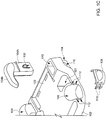
- FIGS 1A through 1E are schematic views illustrating a first embodiment of a child booster seat 100.
- the booster seat 100 can include a seat shell 102 and armrests 104.
- the seat shell 102 can be formed in a single body, for example by injection or blow molding of plastic material.
- the seat shell 102 can have a generally oblong or square shape.
- the upper side of the seat shell 102 can include a support surface 103 on which a child can be seated.
- the support surface 103 toward the rear of the seat shell 102 can also include slits 105 through which resilient latches 107A of a backrest 107 (shown with phantom lines) can be engaged to assemble the backrest 107 with the seat shell 102.
- the backrest 107 may be provided as an optional accessory that can be removable when unused. While the aforementioned construction uses a specific snap engagement, any attachment structures in general may be suitable to attach the backrest 107 with the seat shell 102.
- each of the cup holders 108 can be formed as a bracket having latch prongs 110 that can snap into slits 112 formed on an outer side surface of the seat shell 102 to attach the cup holder 108.
- each of the mount sockets 114 can include a pocket 115 that is closed at the lower side and opened at the upper side of the seat shell 102.
- Each of the mount sockets 114 can include lateral sidewalls provided with latch openings 116 for locking the associated armrest 104 in place.
- the seat shell 102 can further include an inner storage cavity 118 accessible from the lower side of the seat shell 102 and located at a central region between the two mount sockets 114.
- the storage cavity 118 can be defined at the underside of the support surface 103 via molding of the seat shell 102.
- the storage cavity 118 can be at least partially delimited or surrounded by a plurality of sidewalls 118A at the front, rear, right and left side of the seat shell 102.
- One of the sidewalls 118A (e.g., the rear one) can be provided with retainer tabs 120 for holding accessory elements, such as instruction manuals, brochures etc.
- the storage cavity 118 can have a size adapted to receive the placement of the armrests 104, which can be thereby accommodated in an outer envelop of the seat shell 102.
- the seat shell 102 can also include a plurality of pockets or recesses 121 formed at the upper side of the seat shell 102. These pockets or recesses 121 can facilitate hand gripping of the seat shell 102. The bottom surface of the pockets or recesses 121 can also provide additional support for the seat shell 102. Other than the above uses, alternate embodiments may also have the pockets or recesses 121 configured to receive a lower portion of the backrest 107 to hold the backrest 107 with the seat shell 102.
- each of the armrests 104 can have a generally L-shape including an elongated stem 104A upwardly joined with an arm resting portion 104B.
- the stem 104A can have two opposite sidewall surfaces respectively provided with detents 126.
- Each of the detents 126 can be formed as a resilient tab that includes a protruding stud 130 adapted to engage with the corresponding latch opening 116 to lock the armrest 104 in place.
- the armrests 104 can be conveniently placed in the storage cavity 118 when the booster seat 100 is being shipped or unused.
- the armrests 104 can be entirely contained and concealed in the storage cavity 118, so that the outer envelop of the booster seat 100 can be reduced and substantially match with the outer contour shape of the seat shell 102.
- the total size of the booster seat 100 can be reduced to be substantially equal to the size of the seat shell 102.
- the booster seat 100 can be disposed in a smaller package box for storage or shipment. In case the booster seat 100 is to be shipped in batches (for example, from the manufacturer to the point of sales), this configuration can also allow to stack multiple booster seats 100 in a compact manner, as shown in Figure 1F .
- the armrest 104 can be first removed from the storage cavity 118. Then, the stem 104A can be respectively inserted from the upper side of the seat shell 102 into the mount socket 114 until the studs 130 respectively engage with the latch openings 116 and are exposed at the sides of the mount socket 114. Once the studs 130 engage with the latch openings 116, the armrests 104 can be securely locked with the seat shell 102 in a position where the arm resting portion 104B extends above the support surface 103 of the seat shell 102.
- the studs 130 can be pushed inward to disengage from the latch openings 116.
- specific clearance can be provided in the structure of the seat shell 102.
- the sidewalls 118A of the storage cavity 118 that are adjacent to the latch openings 116 can include gaps 132 to facilitate access to the engaged studs 130.
- FIGS 2A through 2C are schematic views illustrating a second embodiment of a booster seat 200.
- the booster seat 200 is generally similar in structure to the embodiment described previously, including a seat shell 202 and armrests 204.
- the seat shell 202 can be formed in a single body, for example by injection or blow molding of plastic material.
- the upper side of the seat shell 202 can define a support surface 203 on which a child can be seated.
- This support surface 203 toward the rear of the seat shell 202 can also include slits 205 for detachably assembling a backrest (not shown).
- Left and right front corners of the seat shell 202 can respectively include recessed cavities 206 where cup holders 208 can be mounted to hold drinking bottles, cups or like containers.
- right and left sides of the seat shell 202 can respectively include mount sockets 214 for assembling the armrests 204.
- each of the mount sockets 214 can include a pocket 215 that is closed at the lower side and opened at the upper side of the seat shell 202.
- the mount socket 214 can have opposite sidewalls provided with latch openings 216 for locking the armrests 204 in place.
- the seat shell 202 can include an inner storage cavity 218 accessible from the lower side of the seat shell 202 and located in a central region between the two mount sockets 214.
- the storage cavity 218 can be formed at the underside of the support surface 203 via molding of the seat shell 202.
- the storage cavity 218 can be at least partially delimited or surrounded by a plurality of sidewalls 218A, and have a size adapted to receive the placement of the armrests 204.
- the seat shell 202 can also include a plurality of pockets or recesses 221 formed at the upper side of the seat shell 202 to facilitate hand gripping of the seat shell 202 and provide additional bottom support.
- Each of the armrests 204 can have a generally L-shape including an elongated stem 204A joined upward with a bent arm resting portion 204B.
- the stem 204A can have two opposite sidewalls respectively provided with protruding studs 226.
- Each of the studs 226 can have a tapered shape including an upper retainer surface 226A and a side angled surface 226B.
- the stem 204A can be inserted from the upper side of the seat shell 202 into the associated mount socket 214.
- the studs 226 may be respectively squeezed and deformed by contact against the inner sidewalls of the mount socket 214 until they reach and permanently engage through the latch openings 216.
- the retainer surface 226A of each stud 226 can abut against an upper rim of the associated latch opening 216 to stop the stud 226.
- the armrest 204 can be thereby locked with the seat shell 20 in a permanent manner, rather than detachably as described in the previous embodiment.
- FIGS 3A through 3E are schematic views illustrating a third embodiment of a booster seat 300.
- the booster seat 300 can include a seat shell 302 and armrests 304. Left and right front corners of the seat shell 302 can be respectively assembled with cup holders 306 to hold drinking bottles, cups or like containers.
- the cup holders 306 may also be constructed such that the bottom surface thereof can rest in contact with the seat of the vehicle on which the booster seat 300 is installed.
- the bottom surface of each cup holder 306 can be formed with a curved shape that can match with that of the vehicle seat, whereby additional support can be provided to improve stability of the booster seat 300.
- FIG. 3D illustrates one example in which each of the cup holders 306 can be formed as a cup-like receptacle having an outer surface provided with a retainer slot 308 that is opened at a lower end, whereas an outer side surface of the seat shell 302 can have a protruding T-shaped rib 310 adapted to engage with the retainer slot 308.
- the cup holder 306 can be assembled with the seat shell 302 for use by engaging the T-shaped rib 310 with the retainer slot 308 from its lower end. When it is unused or convenient storage of the booster seat 300 is needed, the cup holder 306 can be pulled upward to become detached from the seat shell 302. While one specific example has been illustrated, it will be understood that any fasteners for attaching the cup holder 306 may be suitable in general.
- right and left sides of the seat shell 302 can include mount sockets 314 near the rear of the seat shell 302.
- each of the mount sockets 314 can include an aperture 315 that is opened on the upper and lower sides of the seat shell 302.
- Opposite sidewalls of the mount sockets 314 can include latch openings 316 for locking the armrests 304 in place.
- the seat shell 302 can include an inner storage cavity 318 accessible from the underside and located between the two mount sockets 314.
- the storage cavity 318 can be defined at the underside of the support surface 303 at molding of the seat shell 302.
- the storage cavity 318 can be at least partially delimited or surrounded by a plurality of sidewalls 318A at the front, rear, right and left sides of the seat shell 302.
- the storage cavity 318 can be sized to receive the armrests 304 and the cup holders 306 in the outer envelop of the seat shell 302 for facilitating the storage of the booster seat 300.
- each of the armrests 304 can have a stem 304A, a bent arm resting portion 304B joined with an upper end of the stem 304A, and an enlarged base 304C joined with a lower end of the stem 304A.
- a region joining the base 304C with the stem 304A can form a shoulder 320.
- Opposite sidewalls of the stem 304A can also include protruding studs 322 adapted to engage with the latch openings 316 of the mount socket 314 for locking the armrest 304 in place.
- the armrests 304 may be placed in the storage cavity 318 of the seat shell 302 when the booster seat 300 is being shipped or unused.
- the cup holders 306 can also be disassembled from the seat shell 302 and stowed in the storage cavity 318.
- the outer envelop of the booster seat 300 can substantially match with the outer contour shape of the seat shell 302.
- the size of the booster seat 300 can be substantially equal to that of the seat shell 302.
- the armrests 304 are first removed from the storage cavity 318. Then, each of the armrests 304 can be inserted into the aperture 315 of the associated mount socket 314 from the underside of the seat shell 302, and be rotated until the arm resting portion 304B properly extends outward from the upper side and the studs 322 engage with the latch openings 316. The armrests 304 can be thereby locked in place, the base 304C being restrained at the lower side of the seat shell 302, and the arm resting portion 304B extending above the support surface 303 of the seat shell 302.
- the shoulder 320 of the base 304C can abut against an opposing rim of the aperture 315 in the mount socket 314, which can provide effective resistance in addition to the mechanical strength of the snap engagement between the studs 322 and the latch openings 316.
- the cup holder 306 can also be assembled with the seat shell 302 by engaging the T-shaped rib 310 with the retainer slot 308.
- FIGS 4A through 4D are schematic views illustrating a fourth embodiment of a booster seat 400.
- the booster seat 400 can include a seat shell 402 and two armrests 404.
- the seat shell 402 and the armrests 404 are constructed such that the armrests 404 can be nested into an interior of the seat shell 402 and assembled in a use configuration at right and left sides of the seat shell 402.
- the seat shell 402 can be formed integrally as a hollow body, for example by injection or blow molding of plastic material.
- the seat shell 402 can have a generally oblong or square shape, including an inner storage cavity 410 sized to receive the armrests 404.
- the storage cavity 410 can be delimited at least partially by upper and lower envelop portions 412 and 414, and front and rear envelop portions 416 and 418 of the seat shell 402.
- the upper and lower envelop portions 412 and 414 are respectively joined with the front and rear envelop portions 416 and 418 to define the outer contour shape of the seat shell 402, the upper envelop portion 412 defining the support surface where a child can be seated.
- Insert openings 420 are respectively formed at the right and left sides of the seat shell 402 communicating with the storage cavity 410. In this manner, the storage cavity 410 can be accessible via the insert openings 420 to receive the placement of the armrests 404.
- each of the armrests 404 can include an enlarged base 404A, and a bent arm resting portion 404B joined with the base 404A.
- the base 404B can include a lateral protrusion 422 adapted to engage through one corresponding insert opening 420 to hold the armrest 404 at one side of the seat shell 402.
- the armrest 404 can also optionally include a cup holder portion 404C joined with the base 404A (as shown in Figure 4A ).
- the cup holder portion 404C can be formed as a raised portion that is located in front of the arm resting portion 404B, and includes a recess against which a cup holder 430 formed as a bracket can assemble to retain a drinking cup, bottle or the like.
- the armrest 404 including the base 404A, the arm resting portion 404B, the cup holder portion 404C and the lateral protrusion 422, can be formed in a single body.
- the cup holder 430 can be provided as an accessory part that can be assembled with the cup holder portion 404C.
- the armrests 404 can be conveniently placed in the storage cavity 410 when the booster seat 400 is being shipped or unused.
- each of the armrests 404 can be laid down horizontal and nest through the corresponding insert opening 420 into the storage cavity 410 such that the arm resting portion 404B and the cup holder portion 404C are substantially confined in the storage cavity 410, whereas a bottom of the base 404A remains visible from the insert opening 420.
- the outer envelop of the booster seat 400 can substantially match with the outer contour shape of the seat shell 402, which occupies a smaller volume.
- the armrests 404 can be removed from the storage cavity 410 via the insert openings 420, and then erected vertical. Subsequently, the lateral protrusion 422 can be engaged through the insert opening 420 of the seat shell 202.
- the lateral protrusion 422 and the insert opening 420 can be designed to complementarily mate with each other via an interference fit so that the armrest 404 can be securely held with the seat shell 402 in a position where the arm resting portion 404B lies above the support surface of the seat shell 402.
- FIGS 5A and 5B are schematic views illustrating a fifth embodiment of a booster seat 500.
- the booster seat 500 can include a seat shell 502, two armrests 504 and cup holders 506.
- the seat shell 502 can include a storage cavity 514 (shown with phantom lines in Figure 5B ) accessible from an underside of the seat shell 502 and opened at the right and left sides of the seat shell 502 at locations corresponding to the positions of the armrests 504.
- the seat shell 502 and armrests 504 are constructed such that the armrests 504 can be pivotally coupled with the right and left flanks of the seat shell 502 via pivot links 516.
- Each of the pivot links 516 can define a pivot axis that extends generally from the rear to the front of the seat shell 502.
- each of the armrests 504 can be set to a deployed position erected above an upper surface of the seat shell 502 for use.
- the armrests 504 can be operable to rotate from the deployed position toward the bottom of the seat shell 502 (as shown with phantom lines) until they reach a folded position received in the storage cavity 514. Once the armrests 504 are adjusted to the folded position, the outer envelop of the booster seat 500 can substantially match with the outer contour shape of the seat shell 502.
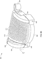
- FIGS. 6A through 6F are schematic views illustrating a sixth embodiment of a booster seat 600.
- the booster seat 600 can include a seat shell 602, two armrests 604 that are pivotally coupled with the right and left flanks of the seat shell 602 via pivot links 606, and cup holders 608.
- An upper side of the seat shell 602 can be detachably mounted with a seat board 610 on which a child can be seated.
- the surface of the seat board 610 can include a plurality of through-holes or apertures 612 so as to provide a breathable surface for increased seating comfort.
- each of the cup holders 608 can be detachably mounted with a side surface of the seat shell 602.
- the cup holder 608 can include a detent portion 614 provided with a stud, and two parallel elongated slots 616 provided at two opposite sides of the detent portion 614.
- a corresponding outer side surface of the seat shell 602 can include an opening 620, and two parallel guide ribs 622 provided at two opposite sides of the opening 620.
- the ribs 622 can cooperate with the elongated slots 616 to guide a sliding movement of the cup holder 608, until the detent portion 614 engages with the opening 620 to hold the cup holder 608 in place.
- the detent portion 614 can be pressed from the inner side of the seat shell 602 to disengage from the opening 620.
- the cup holder 608 then can be removed from the outer side surface of the seat shell 602.
- the interior of the seat shell 602 can include a storage cavity 630 adapted to receive the armrests 604 and the cup holders 608.
- the storage cavity 630 can include a first compartment 632 having a bottom surface 632A, and a second compartment 634 opened at the underside and separated from the first compartment 632 via a sidewall 636.
- the seat board 610 can be detached from the upper side of the seat shell 602 such that the storage cavity 630 is opened and accessible from the upper side.
- the two armrests 604 then can be rotated about their respective pivot axis toward the upper side of the seat shell 602, and then respectively fold into the second compartment 634 of the storage cavity 630.
- the cup holders 608 can also be detached from the respective side surfaces of the seat shell 602, and then disposed in the first compartment 632 of the storage cavity 630. Once the armrests 604 and the cup holders 608 are suitably disposed in the storage cavity 630, the seat board 610 can be mounted to cover the upper side of the seat shell 602 and close the storage cavity 630 from the upper side.
- the outer envelop of the booster seat 600 can substantially match with the outer contour shape of the seat shell 602 which is upwardly closed by the seat board 610. While the booster seat 600 is arranged in this configuration, a child can be seated on the seat board 610 without using the armrests 604 and cup holders 608.
- the seat board 610 can be detached from the seat shell 602.
- the armrests 604 then can be rotated outward until they reach the respective deployed positions shown in Figure 6A .
- the cup holders 608 can also be installed on the side surfaces of the seat shell 602 in the manner described above.
- the seat board 610 can be mounted at the upper side of the seat shell 602 to upwardly close the storage cavity 630. Folding of the armrests 604 into the storage cavity 630 can be thereby prevented.
- Figure 6F is a schematic cross-sectional view taken along section C shown in Figure 6B .
- the seat board 610 can also be constructed to cooperate with each of the armrests 604 disposed in their deployed positions.
- an outer peripheral sidewall of the seat board 610 can include a resilient detent portion 640, and a lower portion of the armrest 604 can have an inner side surface provided with a recess 642.
- the detent portion 640 can resiliently engage with the recess 642. Upward removal of the seat board 610 can be thereby blocked, and the seat board 610 can be securely held in place.
- the outer peripheral sidewall of the seat board 610 from which is formed the detent portion 640 can be operated so as to cause the detent portion 640 to disengage from the recess 642.
- the seat board 610 then can be detached from the seat shell 602 to uncover the storage cavity 630.
- seat board 610 has been described as being removably attached with the seat shell 602, other constructions are possible.
- alternate embodiments may also have the seat board movably connected with the seat shell, e.g., via a pivot or sliding connection. In this manner, the seat board may also be operable to the open and close the storage cavity.
- At least one advantage of the booster seats described herein is the ability to provide a storage cavity in the seat shell that can receive the armrests and cup holders for storage. Accordingly, the booster seats can be packed in smaller boxes, which can effectively reduce the shipment cost.
Landscapes
- Engineering & Computer Science (AREA)
- Transportation (AREA)
- Mechanical Engineering (AREA)
- Aviation & Aerospace Engineering (AREA)
- Health & Medical Sciences (AREA)
- Child & Adolescent Psychology (AREA)
- General Health & Medical Sciences (AREA)
- Physics & Mathematics (AREA)
- Thermal Sciences (AREA)
- Vehicle Step Arrangements And Article Storage (AREA)
- Passenger Equipment (AREA)
- Seats For Vehicles (AREA)
Description
- This application claims priority of
U.S. provisional application no. 61/460,815 filed on January 7, 2011 201110348933.6 filed on November 4, 2011 - The present invention relates to child booster seats, and more particularly to a child booster seat structure that can be arranged in a compact manner.
- Car safety seats for children, as disclosed in
GB 2414660 A - Therefore, there is a need for an improved booster seat that can be manufactured in a cost-effective manner and address at least the foregoing issues.
- The present application describes child booster seats that include a seat shell, and armrests that can be placed in an outer envelop of the seat shell. The armrests can be either placed in a storage cavity of the seat shell, or deployed outside the storage cavity for use. When the armrests are stored in the seat shell, the outer envelop of the booster seat can substantially match with an outer contour shape of the seat shell. Accordingly, the booster seat can occupy a smaller volume and be disposed in a smaller package box for convenient storage. In alternate embodiments, the storage of the armrests in the seat shell can also permit to stack up multiple booster seats in a compact manner, which can reduce the shipment cost of the booster seats.
-
-
Figure 1A is a perspective view illustrating a first embodiment of a booster seat; -
Figure 1B is a perspective view illustrating a bottom side of the first embodiment; -
Figure 1C is a schematic view illustrating how an armrest and a cup holder can be detachably assembled with a seat shell in the first embodiment; -
Figure 1D is a schematic view illustrating one armrest of the first embodiment; -
Figure 1E is a schematic view of the first embodiment in a configuration where the armrests are received in the seat shell; -
Figure 1F is a schematic view illustrating multiple booster seats of the first embodiment stacked upon one another; -
Figure 2A is a perspective view illustrating a second embodiment of a booster seat; -
Figure 2B is an enlarged view illustrating a bottom side of the seat shell of the second embodiment; -
Figure 2C is a partially enlarged view illustrating a bottom side of the seat shell of the second embodiment without assembly of the armrest; -
Figure 3A is a perspective view illustrating a third embodiment of a booster seat; -
Figure 3B is a perspective view illustrating a bottom side of the third embodiment; -
Figure 3C is a schematic view illustrating how an armrest can be assembled with a seat shell in the third embodiment; -
Figure 3D is schematic view illustrating how a cup holder can be assembled with a seat shell in the third embodiment; -
Figure 3E is a schematic view of the third embodiment in a configuration where the armrests are received in the seat shell; -
Figure 4A is a perspective view illustrating a fourth embodiment of a booster seat; -
Figure 4B is a schematic view illustrating the construction of a seat shell used in the fourth embodiment; -
Figure 4C is a schematic view illustrating the construction of an armrest used in the fourth embodiment; -
Figure 4D is a schematic view of the fourth embodiment in a configuration where the armrests are received in the seat shell; -
Figure 5A is a perspective view illustrating a fifth embodiment of a booster seat; -
Figure 5B is a schematic front view illustrating how adjustable armrests are operable to store in the seat shell of the fifth embodiment; -
Figure 6A is a perspective view illustrating a sixth embodiment of a booster seat; -
Figure 6B is another perspective view of the booster seat according to the sixth embodiment; -
Figure 6C is a schematic view illustrating the assembly of a cup holder with the booster seat shown inFigure 6A ; -
Figure 6D is a schematic view illustrating the storage of armrests and cup holders in the booster seat shown inFigure 6A ; -
Figure 6E is a schematic top view illustrating the booster seat shown inFigure 6A with the armrests and cup holders stored therein; and -
Figure 6F is a schematic cross-sectional view taken along section C ofFigure 6B . - The present application describes child booster seats that include a seat shell, and armrests that can be conveniently placed within an outer envelop of the seat shell. The armrests can be stowed in a storage cavity of the seat shell, and deployed outside the storage cavity for use of the booster seat. When the armrests are stored in the seat shell, the outer envelop of the booster seat can substantially match with the outer contour shape of the seat shell. Accordingly, the volume of the booster seat can be reduced to a compact size, which can be packed with a smaller package box. Shipment costs can be thereby reduced. Multiple embodiments of the booster seats are described hereafter with reference to
Figures 1A through 6F . -
Figures 1A through 1E are schematic views illustrating a first embodiment of achild booster seat 100. Thebooster seat 100 can include aseat shell 102 andarmrests 104. Theseat shell 102 can be formed in a single body, for example by injection or blow molding of plastic material. Theseat shell 102 can have a generally oblong or square shape. The upper side of theseat shell 102 can include asupport surface 103 on which a child can be seated. Thesupport surface 103 toward the rear of theseat shell 102 can also includeslits 105 through whichresilient latches 107A of a backrest 107 (shown with phantom lines) can be engaged to assemble thebackrest 107 with theseat shell 102. It is worth noting that thebackrest 107 may be provided as an optional accessory that can be removable when unused. While the aforementioned construction uses a specific snap engagement, any attachment structures in general may be suitable to attach thebackrest 107 with theseat shell 102. - Right and left front corners of the
seat shell 102 can respectively includerecessed cavities 106 wherecup holders 108 can be detachably mounted to hold drinking bottles, cups or containers. As better shown inFigure 1C , each of thecup holders 108 can be formed as a bracket havinglatch prongs 110 that can snap intoslits 112 formed on an outer side surface of theseat shell 102 to attach thecup holder 108. - Right and left sides of the
seat shell 102 can respectively includemount sockets 114 for detachably mounting thearmrests 104. As better shown inFigures 1B and1C , each of themount sockets 114 can include apocket 115 that is closed at the lower side and opened at the upper side of theseat shell 102. Each of themount sockets 114 can include lateral sidewalls provided withlatch openings 116 for locking the associatedarmrest 104 in place. - The
seat shell 102 can further include aninner storage cavity 118 accessible from the lower side of theseat shell 102 and located at a central region between the twomount sockets 114. In one embodiment, thestorage cavity 118 can be defined at the underside of thesupport surface 103 via molding of theseat shell 102. Thestorage cavity 118 can be at least partially delimited or surrounded by a plurality ofsidewalls 118A at the front, rear, right and left side of theseat shell 102. One of thesidewalls 118A (e.g., the rear one) can be provided withretainer tabs 120 for holding accessory elements, such as instruction manuals, brochures etc. Thestorage cavity 118 can have a size adapted to receive the placement of thearmrests 104, which can be thereby accommodated in an outer envelop of theseat shell 102. - Referring again to
Figure 1A , theseat shell 102 can also include a plurality of pockets or recesses 121 formed at the upper side of theseat shell 102. These pockets or recesses 121 can facilitate hand gripping of theseat shell 102. The bottom surface of the pockets or recesses 121 can also provide additional support for theseat shell 102. Other than the above uses, alternate embodiments may also have the pockets or recesses 121 configured to receive a lower portion of thebackrest 107 to hold thebackrest 107 with theseat shell 102. - As better shown in
Figures 1C and1D , each of thearmrests 104 can have a generally L-shape including anelongated stem 104A upwardly joined with anarm resting portion 104B. Thestem 104A can have two opposite sidewall surfaces respectively provided withdetents 126. Each of thedetents 126 can be formed as a resilient tab that includes a protrudingstud 130 adapted to engage with the corresponding latch opening 116 to lock thearmrest 104 in place. - Referring to
Figure 1E , thearmrests 104 can be conveniently placed in thestorage cavity 118 when thebooster seat 100 is being shipped or unused. In this configuration, thearmrests 104 can be entirely contained and concealed in thestorage cavity 118, so that the outer envelop of thebooster seat 100 can be reduced and substantially match with the outer contour shape of theseat shell 102. As a result, the total size of thebooster seat 100 can be reduced to be substantially equal to the size of theseat shell 102. Having a smaller volume, thebooster seat 100 can be disposed in a smaller package box for storage or shipment. In case thebooster seat 100 is to be shipped in batches (for example, from the manufacturer to the point of sales), this configuration can also allow to stackmultiple booster seats 100 in a compact manner, as shown inFigure 1F . - To assemble the
armrest 104 with theseat shell 102, thearmrest 104 can be first removed from thestorage cavity 118. Then, thestem 104A can be respectively inserted from the upper side of theseat shell 102 into themount socket 114 until thestuds 130 respectively engage with thelatch openings 116 and are exposed at the sides of themount socket 114. Once thestuds 130 engage with thelatch openings 116, thearmrests 104 can be securely locked with theseat shell 102 in a position where thearm resting portion 104B extends above thesupport surface 103 of theseat shell 102. - To detach the
armrests 104, thestuds 130 can be pushed inward to disengage from thelatch openings 116. For facilitating access to thestuds 130, specific clearance can be provided in the structure of theseat shell 102. For example, thesidewalls 118A of thestorage cavity 118 that are adjacent to thelatch openings 116 can includegaps 132 to facilitate access to the engagedstuds 130. Once thestuds 130 are disengaged from thelatch openings 116, theunlocked armrests 104 can be entirely removed from themount sockets 114 from the upper side of theseat shell 102. -
Figures 2A through 2C are schematic views illustrating a second embodiment of abooster seat 200. Thebooster seat 200 is generally similar in structure to the embodiment described previously, including aseat shell 202 andarmrests 204. Theseat shell 202 can be formed in a single body, for example by injection or blow molding of plastic material. The upper side of theseat shell 202 can define asupport surface 203 on which a child can be seated. Thissupport surface 203 toward the rear of theseat shell 202 can also includeslits 205 for detachably assembling a backrest (not shown). Left and right front corners of theseat shell 202 can respectively include recessedcavities 206 wherecup holders 208 can be mounted to hold drinking bottles, cups or like containers. Moreover, right and left sides of theseat shell 202 can respectively includemount sockets 214 for assembling thearmrests 204. -
Figure 2B is a partially enlarged view showing a bottom of theseat shell 202, andFigure 2C is a partially enlarged view showing a bottom of theseat shell 202 without assembly of thearmrest 204. As shown, each of themount sockets 214 can include apocket 215 that is closed at the lower side and opened at the upper side of theseat shell 202. Themount socket 214 can have opposite sidewalls provided withlatch openings 216 for locking thearmrests 204 in place. - Referring again to
Figure 2A and2B , theseat shell 202 can include aninner storage cavity 218 accessible from the lower side of theseat shell 202 and located in a central region between the twomount sockets 214. In one embodiment, thestorage cavity 218 can be formed at the underside of thesupport surface 203 via molding of theseat shell 202. Thestorage cavity 218 can be at least partially delimited or surrounded by a plurality of sidewalls 218A, and have a size adapted to receive the placement of thearmrests 204. - Similar to the embodiment described previously, the
seat shell 202 can also include a plurality of pockets or recesses 221 formed at the upper side of theseat shell 202 to facilitate hand gripping of theseat shell 202 and provide additional bottom support. - Each of the
armrests 204 can have a generally L-shape including anelongated stem 204A joined upward with a bentarm resting portion 204B. Thestem 204A can have two opposite sidewalls respectively provided with protrudingstuds 226. Each of thestuds 226 can have a tapered shape including anupper retainer surface 226A and a sideangled surface 226B. - For assembling the
armrest 204 with theseat shell 202, thestem 204A can be inserted from the upper side of theseat shell 202 into the associatedmount socket 214. As thestem 204A is traveling through themount socket 214, thestuds 226 may be respectively squeezed and deformed by contact against the inner sidewalls of themount socket 214 until they reach and permanently engage through thelatch openings 216. Once engaged, theretainer surface 226A of eachstud 226 can abut against an upper rim of the associated latch opening 216 to stop thestud 226. Thearmrest 204 can be thereby locked with the seat shell 20 in a permanent manner, rather than detachably as described in the previous embodiment. -
Figures 3A through 3E are schematic views illustrating a third embodiment of abooster seat 300. Like the embodiments previously described, thebooster seat 300 can include aseat shell 302 andarmrests 304. Left and right front corners of theseat shell 302 can be respectively assembled withcup holders 306 to hold drinking bottles, cups or like containers. In addition, thecup holders 306 may also be constructed such that the bottom surface thereof can rest in contact with the seat of the vehicle on which thebooster seat 300 is installed. In particular, the bottom surface of eachcup holder 306 can be formed with a curved shape that can match with that of the vehicle seat, whereby additional support can be provided to improve stability of thebooster seat 300. - A variety of fastener systems may be used to attach the
cup holders 306 with theseat shell 302.Figure 3D illustrates one example in which each of thecup holders 306 can be formed as a cup-like receptacle having an outer surface provided with aretainer slot 308 that is opened at a lower end, whereas an outer side surface of theseat shell 302 can have a protruding T-shapedrib 310 adapted to engage with theretainer slot 308. Thecup holder 306 can be assembled with theseat shell 302 for use by engaging the T-shapedrib 310 with theretainer slot 308 from its lower end. When it is unused or convenient storage of thebooster seat 300 is needed, thecup holder 306 can be pulled upward to become detached from theseat shell 302. While one specific example has been illustrated, it will be understood that any fasteners for attaching thecup holder 306 may be suitable in general. - Referring to
Figures 3A through 3C , right and left sides of theseat shell 302 can include mountsockets 314 near the rear of theseat shell 302. In this embodiment, each of themount sockets 314 can include anaperture 315 that is opened on the upper and lower sides of theseat shell 302. Opposite sidewalls of themount sockets 314 can includelatch openings 316 for locking thearmrests 304 in place. - As better shown in
Figure 3B , theseat shell 302 can include aninner storage cavity 318 accessible from the underside and located between the twomount sockets 314. In one embodiment, thestorage cavity 318 can be defined at the underside of thesupport surface 303 at molding of theseat shell 302. Thestorage cavity 318 can be at least partially delimited or surrounded by a plurality ofsidewalls 318A at the front, rear, right and left sides of theseat shell 302. Thestorage cavity 318 can be sized to receive thearmrests 304 and thecup holders 306 in the outer envelop of theseat shell 302 for facilitating the storage of thebooster seat 300. - Referring to
Figure 3C , each of thearmrests 304 can have astem 304A, a bentarm resting portion 304B joined with an upper end of thestem 304A, and anenlarged base 304C joined with a lower end of thestem 304A. As thebase 304C is larger than thestem 304A, a region joining thebase 304C with thestem 304A can form ashoulder 320. Opposite sidewalls of thestem 304A can also include protrudingstuds 322 adapted to engage with thelatch openings 316 of themount socket 314 for locking thearmrest 304 in place. - As shown in
Figure 3E , thearmrests 304 may be placed in thestorage cavity 318 of theseat shell 302 when thebooster seat 300 is being shipped or unused. In addition to thearmrests 304, thecup holders 306 can also be disassembled from theseat shell 302 and stowed in thestorage cavity 318. As thearmrests 304 andcup holders 306 can be entirely contained in thestorage cavity 318, the outer envelop of thebooster seat 300 can substantially match with the outer contour shape of theseat shell 302. As a result, the size of thebooster seat 300 can be substantially equal to that of theseat shell 302. - For assembling the
armrests 304 with theseat shell 302, thearmrests 304 are first removed from thestorage cavity 318. Then, each of thearmrests 304 can be inserted into theaperture 315 of the associatedmount socket 314 from the underside of theseat shell 302, and be rotated until thearm resting portion 304B properly extends outward from the upper side and thestuds 322 engage with thelatch openings 316. Thearmrests 304 can be thereby locked in place, thebase 304C being restrained at the lower side of theseat shell 302, and thearm resting portion 304B extending above thesupport surface 303 of theseat shell 302. In case of a crash scenario where upward forces are applied on thearmrest 304 from the underside of theseat shell 302, theshoulder 320 of thebase 304C can abut against an opposing rim of theaperture 315 in themount socket 314, which can provide effective resistance in addition to the mechanical strength of the snap engagement between thestuds 322 and thelatch openings 316. To add further convenience features, thecup holder 306 can also be assembled with theseat shell 302 by engaging the T-shapedrib 310 with theretainer slot 308. -
Figures 4A through 4D are schematic views illustrating a fourth embodiment of abooster seat 400. Thebooster seat 400 can include aseat shell 402 and twoarmrests 404. In this embodiment, theseat shell 402 and thearmrests 404 are constructed such that thearmrests 404 can be nested into an interior of theseat shell 402 and assembled in a use configuration at right and left sides of theseat shell 402. - As better shown in
Figure 4B , theseat shell 402 can be formed integrally as a hollow body, for example by injection or blow molding of plastic material. Theseat shell 402 can have a generally oblong or square shape, including aninner storage cavity 410 sized to receive thearmrests 404. Thestorage cavity 410 can be delimited at least partially by upper andlower envelop portions rear envelop portions seat shell 402. The upper andlower envelop portions rear envelop portions seat shell 402, theupper envelop portion 412 defining the support surface where a child can be seated. Insertopenings 420 are respectively formed at the right and left sides of theseat shell 402 communicating with thestorage cavity 410. In this manner, thestorage cavity 410 can be accessible via theinsert openings 420 to receive the placement of thearmrests 404. - As better shown in
Figure 4C , each of thearmrests 404 can include anenlarged base 404A, and a bentarm resting portion 404B joined with thebase 404A. Thebase 404B can include alateral protrusion 422 adapted to engage through one corresponding insert opening 420 to hold thearmrest 404 at one side of theseat shell 402. As shown, thearmrest 404 can also optionally include acup holder portion 404C joined with thebase 404A (as shown inFigure 4A ). Thecup holder portion 404C can be formed as a raised portion that is located in front of thearm resting portion 404B, and includes a recess against which acup holder 430 formed as a bracket can assemble to retain a drinking cup, bottle or the like. In one embodiment, thearmrest 404, including thebase 404A, thearm resting portion 404B, thecup holder portion 404C and thelateral protrusion 422, can be formed in a single body. Thecup holder 430 can be provided as an accessory part that can be assembled with thecup holder portion 404C. - As shown in
Figure 4D , thearmrests 404 can be conveniently placed in thestorage cavity 410 when thebooster seat 400 is being shipped or unused. In this configuration, each of thearmrests 404 can be laid down horizontal and nest through the corresponding insert opening 420 into thestorage cavity 410 such that thearm resting portion 404B and thecup holder portion 404C are substantially confined in thestorage cavity 410, whereas a bottom of thebase 404A remains visible from theinsert opening 420. Accordingly, the outer envelop of thebooster seat 400 can substantially match with the outer contour shape of theseat shell 402, which occupies a smaller volume. - For assembling the
armrests 404 with theseat shell 402, thearmrests 404 can be removed from thestorage cavity 410 via theinsert openings 420, and then erected vertical. Subsequently, thelateral protrusion 422 can be engaged through the insert opening 420 of theseat shell 202. In one embodiment, thelateral protrusion 422 and theinsert opening 420 can be designed to complementarily mate with each other via an interference fit so that thearmrest 404 can be securely held with theseat shell 402 in a position where thearm resting portion 404B lies above the support surface of theseat shell 402. -
Figures 5A and5B are schematic views illustrating a fifth embodiment of abooster seat 500. Like previously described, thebooster seat 500 can include aseat shell 502, twoarmrests 504 andcup holders 506. Theseat shell 502 can include a storage cavity 514 (shown with phantom lines inFigure 5B ) accessible from an underside of theseat shell 502 and opened at the right and left sides of theseat shell 502 at locations corresponding to the positions of thearmrests 504. In this embodiment, theseat shell 502 andarmrests 504 are constructed such that thearmrests 504 can be pivotally coupled with the right and left flanks of theseat shell 502 via pivot links 516. Each of the pivot links 516 can define a pivot axis that extends generally from the rear to the front of theseat shell 502. As shown inFigure 5A , each of thearmrests 504 can be set to a deployed position erected above an upper surface of theseat shell 502 for use. As shown inFigure 5B , thearmrests 504 can be operable to rotate from the deployed position toward the bottom of the seat shell 502 (as shown with phantom lines) until they reach a folded position received in thestorage cavity 514. Once thearmrests 504 are adjusted to the folded position, the outer envelop of thebooster seat 500 can substantially match with the outer contour shape of theseat shell 502. -
Figure 6A through 6F are schematic views illustrating a sixth embodiment of abooster seat 600. Like the fifth embodiment described inFigures 5A and5B , thebooster seat 600 can include aseat shell 602, twoarmrests 604 that are pivotally coupled with the right and left flanks of theseat shell 602 viapivot links 606, andcup holders 608. An upper side of theseat shell 602 can be detachably mounted with aseat board 610 on which a child can be seated. In one embodiment, the surface of theseat board 610 can include a plurality of through-holes orapertures 612 so as to provide a breathable surface for increased seating comfort. - As shown in
Figure 6C , each of thecup holders 608 can be detachably mounted with a side surface of theseat shell 602. In one embodiment, thecup holder 608 can include adetent portion 614 provided with a stud, and two parallelelongated slots 616 provided at two opposite sides of thedetent portion 614. A corresponding outer side surface of theseat shell 602 can include anopening 620, and twoparallel guide ribs 622 provided at two opposite sides of theopening 620. Theribs 622 can cooperate with theelongated slots 616 to guide a sliding movement of thecup holder 608, until thedetent portion 614 engages with theopening 620 to hold thecup holder 608 in place. To dismount thecup holder 608, thedetent portion 614 can be pressed from the inner side of theseat shell 602 to disengage from theopening 620. Thecup holder 608 then can be removed from the outer side surface of theseat shell 602. - Referring to
Figures 6D and6E , the interior of theseat shell 602 can include astorage cavity 630 adapted to receive thearmrests 604 and thecup holders 608. In one embodiment, thestorage cavity 630 can include afirst compartment 632 having abottom surface 632A, and asecond compartment 634 opened at the underside and separated from thefirst compartment 632 via asidewall 636. - The
seat board 610 can be detached from the upper side of theseat shell 602 such that thestorage cavity 630 is opened and accessible from the upper side. The twoarmrests 604 then can be rotated about their respective pivot axis toward the upper side of theseat shell 602, and then respectively fold into thesecond compartment 634 of thestorage cavity 630. Thecup holders 608 can also be detached from the respective side surfaces of theseat shell 602, and then disposed in thefirst compartment 632 of thestorage cavity 630. Once thearmrests 604 and thecup holders 608 are suitably disposed in thestorage cavity 630, theseat board 610 can be mounted to cover the upper side of theseat shell 602 and close thestorage cavity 630 from the upper side. Accordingly, the outer envelop of thebooster seat 600 can substantially match with the outer contour shape of theseat shell 602 which is upwardly closed by theseat board 610. While thebooster seat 600 is arranged in this configuration, a child can be seated on theseat board 610 without using thearmrests 604 andcup holders 608. - When the use of the
armrests 604 and/or thecup holders 608 is needed, theseat board 610 can be detached from theseat shell 602. Thearmrests 604 then can be rotated outward until they reach the respective deployed positions shown inFigure 6A . Thecup holders 608 can also be installed on the side surfaces of theseat shell 602 in the manner described above. Once thearmrests 604 are suitably deployed, theseat board 610 can be mounted at the upper side of theseat shell 602 to upwardly close thestorage cavity 630. Folding of thearmrests 604 into thestorage cavity 630 can be thereby prevented. -
Figure 6F is a schematic cross-sectional view taken along section C shown inFigure 6B . In one embodiment, theseat board 610 can also be constructed to cooperate with each of thearmrests 604 disposed in their deployed positions. For example, an outer peripheral sidewall of theseat board 610 can include aresilient detent portion 640, and a lower portion of thearmrest 604 can have an inner side surface provided with arecess 642. When thearmrest 604 is disposed in the deployed position and theseat board 610 installed at the upper side of theseat shell 602, thedetent portion 640 can resiliently engage with therecess 642. Upward removal of theseat board 610 can be thereby blocked, and theseat board 610 can be securely held in place. To remove theseat board 610, the outer peripheral sidewall of theseat board 610 from which is formed thedetent portion 640 can be operated so as to cause thedetent portion 640 to disengage from therecess 642. Theseat board 610 then can be detached from theseat shell 602 to uncover thestorage cavity 630. - While the
seat board 610 has been described as being removably attached with theseat shell 602, other constructions are possible. For example, alternate embodiments may also have the seat board movably connected with the seat shell, e.g., via a pivot or sliding connection. In this manner, the seat board may also be operable to the open and close the storage cavity. - At least one advantage of the booster seats described herein is the ability to provide a storage cavity in the seat shell that can receive the armrests and cup holders for storage. Accordingly, the booster seats can be packed in smaller boxes, which can effectively reduce the shipment cost.
- Realizations in accordance with the present invention therefore have been described only in the context of particular embodiments. These embodiments are meant to be illustrative and not limiting.
Claims (15)
- A child booster seat comprising:a seat shell (502, 602) having an inner storage cavity (514, 630); andan armrest (504, 604) assembled with the seat shell, the armrest being pivotally connected with the seat shell;wherein the storage cavity is adapted to receive the armrest, the armrest being placed in the storage cavity for storage, and deployed outside the storage cavity for use.
- The booster seat according to claim 1, wherein the armrest (504, 604) is operable to rotate relative to the seat shell until the armrest reaches a folded position received in the storage cavity (514, 630).
- The booster seat according to claim 1 or 2, wherein the seat shell has a support surface for seating a child, and the storage cavity (514) is accessible from an underside of the support surface.
- The booster seat according to claim 1 or 2, wherein the seat shell has an upper side provided with a seat board (610) that is operable to close and open the storage cavity from the upper side of the seat shell.
- The booster seat according to claim 1, further including a cup holder (608) operable to detachably mount with a side surface of the seat shell, the storage cavity being further adapted to store the cup holder with the armrest.
- A child booster seat comprising:a seat shell (102, 202, 302, 402, 502, 602) having an outer surface and an inner storage cavity (118, 218, 318, 410, 514, 630);a cup holder (108, 208, 306, 608) operable to detachably mount with a side surface of the seat shell; andan armrest (104, 204, 304, 404, 504, 604) operable to detachably assemble with the seat shell;wherein the storage cavity (318, 630) is adapted to receive the armrest and the cup holder, the armrest and the cup holder being placed in the storage cavity for storage, and deployed outside the storage cavity for use.
- The booster seat according to claim 6, wherein the seat shell includes a mount socket (114, 214, 314) into which the armrest (104, 204, 304) is engaged to fixedly assemble the armrest with the seat shell in a use configuration.
- The booster seat according to claim 7, wherein the armrest (104, 204) includes a protruding stud (130, 226) that comes into locking engagement with a latch opening (116, 216) formed on an inner sidewall of the mount socket (114, 214) as the armrest is inserted into the mount socket.
- The booster seat according to claim 7, wherein the mount socket (114, 214) is opened at an upper side of the seat shell from which the armrest (104, 204) is inserted into the mount socket.
- The booster seat according to claim 7, wherein the mount socket (314) includes an aperture (315) that is respectively opened at an upper and lower side of the seat shell, and the armrest (304) is adapted to mount through the aperture from the lower side of the seat shell.
- The booster seat according to claim 10, wherein the armrest (304) has an enlarged base (304C) that is adapted to abut against an upper rim of the aperture (315) to prevent removal of the armrest from the upper side of the seat shell.
- The booster seat according to claim 10, wherein the armrest (304) includes at least one stud (322), and the mount socket (314) includes at least one latch opening (316), the armrest being adapted to insert into the aperture (315) from the lower side of the seat shell, and to rotate until a portion (304B) of the armrest extends outward from the upper side and the stud engages with the latch opening.
- A child booster seat comprising:a seat shell (102, 202, 302, 402, 502, 602) having an inner storage cavity (118, 218, 318, 410, 514, 630), wherein the storage cavity (410) is at least partially delimited between an upper surface (412) and a lower surface (414) of the seat shell and is accessible via an insert opening (420) formed at a lateral side of the seat shell; andan armrest (104, 204, 304, 404, 504, 604) operable to detachably assemble with the seat shell, wherein the armrest (404) is adapted to nest through the insert opening into the storage cavity such that the armrest is substantially confined in the storage cavity and has a bottom remaining visible from the insert opening;wherein the armrest is placed in the storage cavity for storage, and deployed outside the storage cavity for use.
- The booster seat according to claim 13, wherein the armrest includes a base, and an arm resting portion joined with the base, the armrest being adapted to nest through the insert opening into the storage cavity such that the arm resting portion is substantially confined in the storage cavity and a bottom of the base remains visible from the insert opening.
- The booster seat according to claim 14, wherein the base of the armrest includes a lateral protrusion adapted to complementarily mate with the insert opening via an interference fit to hold the armrest in a position where the arm resting portion extends above the seat shell.
Priority Applications (1)
| Application Number | Priority Date | Filing Date | Title |
|---|---|---|---|
| PL12150173T PL2474441T3 (en) | 2011-01-07 | 2012-01-04 | Booster seat |
Applications Claiming Priority (2)
| Application Number | Priority Date | Filing Date | Title |
|---|---|---|---|
| US201161460815P | 2011-01-07 | 2011-01-07 | |
| CN201110348933.6A CN102582480B (en) | 2011-01-07 | 2011-11-04 | Booster seat |
Publications (2)
| Publication Number | Publication Date |
|---|---|
| EP2474441A1 EP2474441A1 (en) | 2012-07-11 |
| EP2474441B1 true EP2474441B1 (en) | 2017-11-01 |
Family
ID=46471918
Family Applications (1)
| Application Number | Title | Priority Date | Filing Date |
|---|---|---|---|
| EP12150173.8A Active EP2474441B1 (en) | 2011-01-07 | 2012-01-04 | Booster seat |
Country Status (7)
| Country | Link |
|---|---|
| US (1) | US8960793B2 (en) |
| EP (1) | EP2474441B1 (en) |
| JP (2) | JP5425175B2 (en) |
| CN (2) | CN102582480B (en) |
| BR (1) | BR102012000351B1 (en) |
| ES (1) | ES2654571T3 (en) |
| PL (1) | PL2474441T3 (en) |
Cited By (1)
| Publication number | Priority date | Publication date | Assignee | Title |
|---|---|---|---|---|
| US11912182B2 (en) | 2020-10-30 | 2024-02-27 | Wonderland Switzerland Ag | Fixing device for an armrest of an automobile seat and automobile seats |
Families Citing this family (23)
| Publication number | Priority date | Publication date | Assignee | Title |
|---|---|---|---|---|
| US8382202B2 (en) * | 2010-05-26 | 2013-02-26 | Wonderland Nurserygoods Company Limited | Stackable child safety seat |
| FR2985465A1 (en) * | 2012-01-06 | 2013-07-12 | Peugeot Citroen Automobiles Sa | VEHICLE SEAT COMPRISING A SEAT WITH REMOVABLE SEAT ELEMENTS |
| CN202686063U (en) * | 2012-07-02 | 2013-01-23 | 宝钜(中国)儿童用品有限公司 | Cup holder connecting structure and seat with connecting structure |
| US9376037B1 (en) * | 2013-07-09 | 2016-06-28 | Baby Trend, Inc. | Car seat |
| TR201815644T4 (en) * | 2013-10-23 | 2018-11-21 | Wonderland Switzerland Ag | Child safety seat. |
| JP5893089B2 (en) * | 2014-07-07 | 2016-03-23 | 三菱電機株式会社 | Control method of DC converter |
| US20160059762A1 (en) * | 2014-08-28 | 2016-03-03 | Goodbaby Child Product Co., Ltd. | Integrated Rotatable Cup Holder |
| GB2537798A (en) * | 2014-11-11 | 2016-11-02 | James Hicks Ben | Child car seat |
| FR3035833A1 (en) * | 2015-05-06 | 2016-11-11 | Dorel France Sa | CHILD CAR SEAT HAVING ADJUSTABLE STRAP GUIDING ELEMENTS |
| US10112508B2 (en) * | 2015-08-05 | 2018-10-30 | Evenflo Company, Inc. | Harness booster car seat convertible to multiple separately usable configurations |
| GB2548240A (en) * | 2016-03-08 | 2017-09-13 | Graco Children's Products Inc | Apparatus and method for an adjustable cup holder |
| US10562419B2 (en) * | 2016-08-19 | 2020-02-18 | Graco Children's Products, Inc. | Child's booster seat |
| US10300826B2 (en) * | 2016-09-01 | 2019-05-28 | Dorel Juvenile Group, Inc. | Juvenile vehicle seat with cupholder |
| CN207101011U (en) * | 2016-09-14 | 2018-03-16 | 儿童二代公司 | With can collecting pallet compartment and bedplate padded chair |
| GB2571662B (en) * | 2017-01-12 | 2019-12-25 | Wonderland Switzerland Ag | Belt-positioning seat incorporable into a child safety seat and detachable for independent use |
| DE102017106144A1 (en) * | 2017-03-22 | 2018-09-27 | Kettler Alu-Rad GmbH | Bicycle child seat with integrated cup holder |
| KR102540926B1 (en) * | 2018-10-02 | 2023-06-08 | 현대자동차주식회사 | Booster seat |
| DE102019100145A1 (en) * | 2019-01-04 | 2020-07-09 | Johannes Sklenarz | Child seat with a ventilation system |
| CN110641328A (en) * | 2019-10-09 | 2020-01-03 | 浙江感恩科技股份有限公司 | Armrest structure of child safety seat |
| CN113895326B (en) * | 2020-07-06 | 2024-09-13 | 宝钜瑞士股份有限公司 | Child safety seat and removable side-impact protection block |
| USD961946S1 (en) | 2020-08-31 | 2022-08-30 | Kids2, Inc. | Booster seat |
| FR3118730B1 (en) * | 2021-01-11 | 2022-11-25 | Psa Automobiles Sa | SEAT RAISER FOR A VEHICLE SEAT, WITH TENSION REDUCTION DURING A FRONT IMPACT |
| WO2022187213A1 (en) * | 2021-03-01 | 2022-09-09 | Breana Monique Armstrong | Convertible child seat device with pockets |
Family Cites Families (26)
| Publication number | Priority date | Publication date | Assignee | Title |
|---|---|---|---|---|
| US1898008A (en) * | 1931-07-29 | 1933-02-21 | Fred G Fox | Arm support for auto rumble seats |
| US1993437A (en) * | 1932-12-07 | 1935-03-05 | Simmons Co | Furniture construction |
| US4858869A (en) * | 1988-09-20 | 1989-08-22 | Stang Michael Andrew | Cup attachment system |
| GB2262511B (en) * | 1991-12-06 | 1995-05-31 | Derrick John Martin Barker | Booster seat container |
| DE59603047D1 (en) | 1995-06-30 | 1999-10-21 | Margarete Schraeder | Child car seat |
| US5964502A (en) | 1996-10-25 | 1999-10-12 | Evenflo Company, Inc. | High-back child restraint system |
| JPH10338066A (en) * | 1997-06-06 | 1998-12-22 | Aichi Mach Ind Co Ltd | Detachable seat |
| US6478372B1 (en) * | 1999-05-25 | 2002-11-12 | Graco Children's Products Inc. | Armrests for car seats |
| JP2001047904A (en) | 1999-08-03 | 2001-02-20 | Minoru Kasei Kk | Junior seat with seat height adjusting mechanism |
| JP2001047903A (en) | 1999-08-03 | 2001-02-20 | Minoru Kasei Kk | Junior seat with opening/closing guard |
| US6705675B1 (en) * | 2000-05-08 | 2004-03-16 | Graco Children's Products Inc. | Adjustable child seat for toddlers to small children |
| US6467839B1 (en) * | 2000-09-22 | 2002-10-22 | Cosco Management, Inc. | Juvenile seat article holder |
| US6520586B2 (en) * | 2001-05-22 | 2003-02-18 | In Hyuk Park | Seating structure equipped with retractable armrest |
| US7066536B2 (en) * | 2002-02-11 | 2006-06-27 | Graco Children's Products Inc. | Child seat |
| GB2414662B (en) | 2002-02-11 | 2006-11-08 | Graco Childrens Prod Inc | Child seat |
| KR20040022099A (en) * | 2002-09-06 | 2004-03-11 | 기아자동차주식회사 | Improved seat |
| JP2005538764A (en) * | 2002-09-12 | 2005-12-22 | パク,キ−ス | Multipurpose car seat for infants |
| TWM274273U (en) | 2004-12-13 | 2005-09-01 | Link Treasure Ltd | Connection structure of infant car seat |
| CN201124775Y (en) * | 2007-10-29 | 2008-10-01 | 好孩子儿童用品有限公司 | Seat of children's car |
| US20090115230A1 (en) * | 2007-11-04 | 2009-05-07 | Robert Evan Haut | Child safety seat |
| CN101659224B (en) * | 2008-06-25 | 2011-11-23 | 明门香港股份有限公司 | Child chair |
| CN101480930A (en) * | 2009-02-12 | 2009-07-15 | 好孩子儿童用品有限公司 | Vehicle seat for children |
| CN201362194Y (en) | 2009-02-12 | 2009-12-16 | 好孩子儿童用品有限公司 | Child car seat |
| JP5441444B2 (en) | 2009-03-02 | 2014-03-12 | 株式会社カーメイト | Child seat for vehicle |
| CN201472192U (en) * | 2009-06-17 | 2010-05-19 | 好孩子儿童用品有限公司 | Children vehicle seat |
| CN201484232U (en) | 2009-08-06 | 2010-05-26 | 宁波艾贝汽车安全系统有限公司 | Detachable child seat |
-
2011
- 2011-11-04 CN CN201110348933.6A patent/CN102582480B/en active Active
- 2011-11-04 CN CN201310333122.8A patent/CN103434422B/en active Active
- 2011-12-20 JP JP2011278425A patent/JP5425175B2/en active Active
- 2011-12-28 US US13/338,460 patent/US8960793B2/en active Active
-
2012
- 2012-01-04 PL PL12150173T patent/PL2474441T3/en unknown
- 2012-01-04 EP EP12150173.8A patent/EP2474441B1/en active Active
- 2012-01-04 ES ES12150173.8T patent/ES2654571T3/en active Active
- 2012-01-06 BR BR102012000351A patent/BR102012000351B1/en active IP Right Grant
-
2013
- 2013-10-09 JP JP2013211908A patent/JP5689160B2/en active Active
Non-Patent Citations (1)
| Title |
|---|
| None * |
Cited By (2)
| Publication number | Priority date | Publication date | Assignee | Title |
|---|---|---|---|---|
| US11912182B2 (en) | 2020-10-30 | 2024-02-27 | Wonderland Switzerland Ag | Fixing device for an armrest of an automobile seat and automobile seats |
| DE102022103946B4 (en) | 2020-10-30 | 2024-10-24 | Wonderland Switzerland Ag | FASTENING DEVICE FOR A CAR SEAT ARMREST AND CAR SEATS |
Also Published As
| Publication number | Publication date |
|---|---|
| US8960793B2 (en) | 2015-02-24 |
| ES2654571T3 (en) | 2018-02-14 |
| US20120175922A1 (en) | 2012-07-12 |
| JP2014028305A (en) | 2014-02-13 |
| JP2012144249A (en) | 2012-08-02 |
| EP2474441A1 (en) | 2012-07-11 |
| CN102582480B (en) | 2014-07-09 |
| CN103434422B (en) | 2016-03-30 |
| JP5425175B2 (en) | 2014-02-26 |
| JP5689160B2 (en) | 2015-03-25 |
| CN102582480A (en) | 2012-07-18 |
| BR102012000351B1 (en) | 2020-05-05 |
| CN103434422A (en) | 2013-12-11 |
| PL2474441T3 (en) | 2018-04-30 |
| BR102012000351A2 (en) | 2013-07-02 |
Similar Documents
| Publication | Publication Date | Title |
|---|---|---|
| EP2474441B1 (en) | Booster seat | |
| US9603464B2 (en) | Booster seat with stowable tray and/or stowable securing strap | |
| US8540312B2 (en) | Infant support with independently repositionable legs | |
| US9346387B2 (en) | Cup holder and storage bin assembly | |
| US8424900B2 (en) | Stroller trays and methods of mounting the same on strollers | |
| US20070046058A1 (en) | Removable storage console | |
| US20170119172A1 (en) | Booster seat with stowable tray compartment and base panel | |
| US20130193708A1 (en) | Package tray with cargo catchment | |
| CN211844262U (en) | Vehicle with a steering wheel | |
| GB2585163A (en) | Child safety seat | |
| US9490461B2 (en) | Storage system for passenger vehicle | |
| US20020134807A1 (en) | Pivot down container holder and tray combination | |
| EP3640137B1 (en) | Armrest assembly with in-arm cup holder | |
| GB2447708A (en) | Booster cushion | |
| US9371019B2 (en) | Child seat and method of fabricating the same | |
| US11731550B2 (en) | Cup holder assembly bracket | |
| JP2014058271A (en) | Vehicle console | |
| EP3295832A1 (en) | Booster seat with stowable tray compartment and base panel | |
| JP5432663B2 (en) | Vehicle storage pocket | |
| JPS6345920Y2 (en) | ||
| JP6418489B2 (en) | Car luggage compartment structure | |
| CN214231147U (en) | Vehicle-mounted paper extraction box | |
| JP4016087B2 (en) | Car interior storage structure | |
| JPH02220936A (en) | Rear seat construction for automobile | |
| KR200397532Y1 (en) | car rear seat console box |
Legal Events
| Date | Code | Title | Description |
|---|---|---|---|
| PUAI | Public reference made under article 153(3) epc to a published international application that has entered the european phase |
Free format text: ORIGINAL CODE: 0009012 |
|
| 17P | Request for examination filed |
Effective date: 20120104 |
|
| AK | Designated contracting states |
Kind code of ref document: A1 Designated state(s): AL AT BE BG CH CY CZ DE DK EE ES FI FR GB GR HR HU IE IS IT LI LT LU LV MC MK MT NL NO PL PT RO RS SE SI SK SM TR |
|
| AX | Request for extension of the european patent |
Extension state: BA ME |
|
| GRAP | Despatch of communication of intention to grant a patent |
Free format text: ORIGINAL CODE: EPIDOSNIGR1 |
|
| INTG | Intention to grant announced |
Effective date: 20170516 |
|
| RAP1 | Party data changed (applicant data changed or rights of an application transferred) |
Owner name: WONDERLAND NURSERYGOODS COMPANY LIMITED |
|
| GRAS | Grant fee paid |
Free format text: ORIGINAL CODE: EPIDOSNIGR3 |
|
| GRAA | (expected) grant |
Free format text: ORIGINAL CODE: 0009210 |
|
| AK | Designated contracting states |
Kind code of ref document: B1 Designated state(s): AL AT BE BG CH CY CZ DE DK EE ES FI FR GB GR HR HU IE IS IT LI LT LU LV MC MK MT NL NO PL PT RO RS SE SI SK SM TR |
|
| REG | Reference to a national code |
Ref country code: GB Ref legal event code: FG4D |
|
| REG | Reference to a national code |
Ref country code: CH Ref legal event code: EP Ref country code: AT Ref legal event code: REF Ref document number: 941694 Country of ref document: AT Kind code of ref document: T Effective date: 20171115 |
|
| REG | Reference to a national code |
Ref country code: IE Ref legal event code: FG4D |
|
| REG | Reference to a national code |
Ref country code: CH Ref legal event code: NV Representative=s name: E. BLUM AND CO. AG PATENT- UND MARKENANWAELTE , CH |
|
| REG | Reference to a national code |
Ref country code: DE Ref legal event code: R096 Ref document number: 602012039110 Country of ref document: DE |
|
| REG | Reference to a national code |
Ref country code: DE Ref legal event code: R082 Ref document number: 602012039110 Country of ref document: DE Representative=s name: EPPING HERMANN FISCHER PATENTANWALTSGESELLSCHA, DE Ref country code: DE Ref legal event code: R081 Ref document number: 602012039110 Country of ref document: DE Owner name: WONDERLAND SWITZERLAND AG, CH Free format text: FORMER OWNER: WONDERLAND NURSERYGOODS COMPANY LIMITED, HONG KONG, HK |
|
| REG | Reference to a national code |
Ref country code: FR Ref legal event code: PLFP Year of fee payment: 7 |
|
| REG | Reference to a national code |
Ref country code: NL Ref legal event code: FP |
|
| REG | Reference to a national code |
Ref country code: ES Ref legal event code: FG2A Ref document number: 2654571 Country of ref document: ES Kind code of ref document: T3 Effective date: 20180214 |
|
| REG | Reference to a national code |
Ref country code: LT Ref legal event code: MG4D |
|
| REG | Reference to a national code |
Ref country code: GB Ref legal event code: 732E Free format text: REGISTERED BETWEEN 20180315 AND 20180326 |
|
| REG | Reference to a national code |
Ref country code: AT Ref legal event code: MK05 Ref document number: 941694 Country of ref document: AT Kind code of ref document: T Effective date: 20171101 |
|
| PG25 | Lapsed in a contracting state [announced via postgrant information from national office to epo] |
Ref country code: SE Free format text: LAPSE BECAUSE OF FAILURE TO SUBMIT A TRANSLATION OF THE DESCRIPTION OR TO PAY THE FEE WITHIN THE PRESCRIBED TIME-LIMIT Effective date: 20171101 Ref country code: LT Free format text: LAPSE BECAUSE OF FAILURE TO SUBMIT A TRANSLATION OF THE DESCRIPTION OR TO PAY THE FEE WITHIN THE PRESCRIBED TIME-LIMIT Effective date: 20171101 Ref country code: NO Free format text: LAPSE BECAUSE OF FAILURE TO SUBMIT A TRANSLATION OF THE DESCRIPTION OR TO PAY THE FEE WITHIN THE PRESCRIBED TIME-LIMIT Effective date: 20180201 Ref country code: FI Free format text: LAPSE BECAUSE OF FAILURE TO SUBMIT A TRANSLATION OF THE DESCRIPTION OR TO PAY THE FEE WITHIN THE PRESCRIBED TIME-LIMIT Effective date: 20171101 |
|
| PG25 | Lapsed in a contracting state [announced via postgrant information from national office to epo] |
Ref country code: RS Free format text: LAPSE BECAUSE OF FAILURE TO SUBMIT A TRANSLATION OF THE DESCRIPTION OR TO PAY THE FEE WITHIN THE PRESCRIBED TIME-LIMIT Effective date: 20171101 Ref country code: LV Free format text: LAPSE BECAUSE OF FAILURE TO SUBMIT A TRANSLATION OF THE DESCRIPTION OR TO PAY THE FEE WITHIN THE PRESCRIBED TIME-LIMIT Effective date: 20171101 Ref country code: HR Free format text: LAPSE BECAUSE OF FAILURE TO SUBMIT A TRANSLATION OF THE DESCRIPTION OR TO PAY THE FEE WITHIN THE PRESCRIBED TIME-LIMIT Effective date: 20171101 Ref country code: BG Free format text: LAPSE BECAUSE OF FAILURE TO SUBMIT A TRANSLATION OF THE DESCRIPTION OR TO PAY THE FEE WITHIN THE PRESCRIBED TIME-LIMIT Effective date: 20180201 Ref country code: GR Free format text: LAPSE BECAUSE OF FAILURE TO SUBMIT A TRANSLATION OF THE DESCRIPTION OR TO PAY THE FEE WITHIN THE PRESCRIBED TIME-LIMIT Effective date: 20180202 Ref country code: AT Free format text: LAPSE BECAUSE OF FAILURE TO SUBMIT A TRANSLATION OF THE DESCRIPTION OR TO PAY THE FEE WITHIN THE PRESCRIBED TIME-LIMIT Effective date: 20171101 Ref country code: IS Free format text: LAPSE BECAUSE OF FAILURE TO SUBMIT A TRANSLATION OF THE DESCRIPTION OR TO PAY THE FEE WITHIN THE PRESCRIBED TIME-LIMIT Effective date: 20180301 |
|
| PG25 | Lapsed in a contracting state [announced via postgrant information from national office to epo] |
Ref country code: EE Free format text: LAPSE BECAUSE OF FAILURE TO SUBMIT A TRANSLATION OF THE DESCRIPTION OR TO PAY THE FEE WITHIN THE PRESCRIBED TIME-LIMIT Effective date: 20171101 Ref country code: CY Free format text: LAPSE BECAUSE OF FAILURE TO SUBMIT A TRANSLATION OF THE DESCRIPTION OR TO PAY THE FEE WITHIN THE PRESCRIBED TIME-LIMIT Effective date: 20171101 Ref country code: SK Free format text: LAPSE BECAUSE OF FAILURE TO SUBMIT A TRANSLATION OF THE DESCRIPTION OR TO PAY THE FEE WITHIN THE PRESCRIBED TIME-LIMIT Effective date: 20171101 Ref country code: DK Free format text: LAPSE BECAUSE OF FAILURE TO SUBMIT A TRANSLATION OF THE DESCRIPTION OR TO PAY THE FEE WITHIN THE PRESCRIBED TIME-LIMIT Effective date: 20171101 Ref country code: CZ Free format text: LAPSE BECAUSE OF FAILURE TO SUBMIT A TRANSLATION OF THE DESCRIPTION OR TO PAY THE FEE WITHIN THE PRESCRIBED TIME-LIMIT Effective date: 20171101 |
|
| REG | Reference to a national code |
Ref country code: DE Ref legal event code: R097 Ref document number: 602012039110 Country of ref document: DE |
|
| PG25 | Lapsed in a contracting state [announced via postgrant information from national office to epo] |
Ref country code: SM Free format text: LAPSE BECAUSE OF FAILURE TO SUBMIT A TRANSLATION OF THE DESCRIPTION OR TO PAY THE FEE WITHIN THE PRESCRIBED TIME-LIMIT Effective date: 20171101 Ref country code: RO Free format text: LAPSE BECAUSE OF FAILURE TO SUBMIT A TRANSLATION OF THE DESCRIPTION OR TO PAY THE FEE WITHIN THE PRESCRIBED TIME-LIMIT Effective date: 20171101 |
|
| PLBE | No opposition filed within time limit |
Free format text: ORIGINAL CODE: 0009261 |
|
| STAA | Information on the status of an ep patent application or granted ep patent |
Free format text: STATUS: NO OPPOSITION FILED WITHIN TIME LIMIT |
|
| 26N | No opposition filed |
Effective date: 20180802 |
|
| PG25 | Lapsed in a contracting state [announced via postgrant information from national office to epo] |
Ref country code: LU Free format text: LAPSE BECAUSE OF NON-PAYMENT OF DUE FEES Effective date: 20180104 |
|
| REG | Reference to a national code |
Ref country code: IE Ref legal event code: MM4A |
|
| REG | Reference to a national code |
Ref country code: BE Ref legal event code: MM Effective date: 20180131 |
|
| PG25 | Lapsed in a contracting state [announced via postgrant information from national office to epo] |
Ref country code: BE Free format text: LAPSE BECAUSE OF NON-PAYMENT OF DUE FEES Effective date: 20180131 Ref country code: SI Free format text: LAPSE BECAUSE OF FAILURE TO SUBMIT A TRANSLATION OF THE DESCRIPTION OR TO PAY THE FEE WITHIN THE PRESCRIBED TIME-LIMIT Effective date: 20171101 |
|
| PG25 | Lapsed in a contracting state [announced via postgrant information from national office to epo] |
Ref country code: IE Free format text: LAPSE BECAUSE OF NON-PAYMENT OF DUE FEES Effective date: 20180104 |
|
| REG | Reference to a national code |
Ref country code: CH Ref legal event code: PUE Owner name: WONDERLAND SWITZERLAND AG, CH Free format text: FORMER OWNER: WONDERLAND NURSERYGOODS COMPANY LIMITED, CN |
|
| REG | Reference to a national code |
Ref country code: NL Ref legal event code: PD Owner name: WONDERLAND SWITZERLAND AG; CH Free format text: DETAILS ASSIGNMENT: CHANGE OF OWNER(S), ASSIGNMENT; FORMER OWNER NAME: WONDERLAND NURSERYGOODS COMPANY LIMITED Effective date: 20190509 |
|
| REG | Reference to a national code |
Ref country code: ES Ref legal event code: PC2A Owner name: WONDERLAND SWITZERLAND AG Effective date: 20190520 |
|
| PG25 | Lapsed in a contracting state [announced via postgrant information from national office to epo] |
Ref country code: MC Free format text: LAPSE BECAUSE OF FAILURE TO SUBMIT A TRANSLATION OF THE DESCRIPTION OR TO PAY THE FEE WITHIN THE PRESCRIBED TIME-LIMIT Effective date: 20171101 |
|
| REG | Reference to a national code |
Ref country code: CH Ref legal event code: NV Representative=s name: FELBER UND PARTNER AG, CH |
|
| PG25 | Lapsed in a contracting state [announced via postgrant information from national office to epo] |
Ref country code: MT Free format text: LAPSE BECAUSE OF NON-PAYMENT OF DUE FEES Effective date: 20180104 |
|
| PG25 | Lapsed in a contracting state [announced via postgrant information from national office to epo] |
Ref country code: TR Free format text: LAPSE BECAUSE OF FAILURE TO SUBMIT A TRANSLATION OF THE DESCRIPTION OR TO PAY THE FEE WITHIN THE PRESCRIBED TIME-LIMIT Effective date: 20171101 |
|
| PG25 | Lapsed in a contracting state [announced via postgrant information from national office to epo] |
Ref country code: PT Free format text: LAPSE BECAUSE OF FAILURE TO SUBMIT A TRANSLATION OF THE DESCRIPTION OR TO PAY THE FEE WITHIN THE PRESCRIBED TIME-LIMIT Effective date: 20171101 Ref country code: HU Free format text: LAPSE BECAUSE OF FAILURE TO SUBMIT A TRANSLATION OF THE DESCRIPTION OR TO PAY THE FEE WITHIN THE PRESCRIBED TIME-LIMIT; INVALID AB INITIO Effective date: 20120104 |
|
| PG25 | Lapsed in a contracting state [announced via postgrant information from national office to epo] |
Ref country code: MK Free format text: LAPSE BECAUSE OF NON-PAYMENT OF DUE FEES Effective date: 20171101 |
|
| PG25 | Lapsed in a contracting state [announced via postgrant information from national office to epo] |
Ref country code: AL Free format text: LAPSE BECAUSE OF FAILURE TO SUBMIT A TRANSLATION OF THE DESCRIPTION OR TO PAY THE FEE WITHIN THE PRESCRIBED TIME-LIMIT Effective date: 20171101 |
|
| P01 | Opt-out of the competence of the unified patent court (upc) registered |
Effective date: 20230522 |
|
| PGFP | Annual fee paid to national office [announced via postgrant information from national office to epo] |
Ref country code: PL Payment date: 20231227 Year of fee payment: 13 Ref country code: NL Payment date: 20240125 Year of fee payment: 13 |
|
| PGFP | Annual fee paid to national office [announced via postgrant information from national office to epo] |
Ref country code: ES Payment date: 20240209 Year of fee payment: 13 |
|
| PGFP | Annual fee paid to national office [announced via postgrant information from national office to epo] |
Ref country code: DE Payment date: 20231222 Year of fee payment: 13 Ref country code: CH Payment date: 20240201 Year of fee payment: 13 Ref country code: GB Payment date: 20240102 Year of fee payment: 13 |
|
| PGFP | Annual fee paid to national office [announced via postgrant information from national office to epo] |
Ref country code: IT Payment date: 20240119 Year of fee payment: 13 Ref country code: FR Payment date: 20240102 Year of fee payment: 13 |