EP2473992B1 - Schalldämpfende belüftungsdüse, schalldämpfende verkleidung und verfahren zur bereitstellung einer schalldämpfenden belüftungsdüse - Google Patents
Schalldämpfende belüftungsdüse, schalldämpfende verkleidung und verfahren zur bereitstellung einer schalldämpfenden belüftungsdüse Download PDFInfo
- Publication number
- EP2473992B1 EP2473992B1 EP10754775.4A EP10754775A EP2473992B1 EP 2473992 B1 EP2473992 B1 EP 2473992B1 EP 10754775 A EP10754775 A EP 10754775A EP 2473992 B1 EP2473992 B1 EP 2473992B1
- Authority
- EP
- European Patent Office
- Prior art keywords
- sound
- vent
- lining
- sound absorbing
- strips
- Prior art date
- Legal status (The legal status is an assumption and is not a legal conclusion. Google has not performed a legal analysis and makes no representation as to the accuracy of the status listed.)
- Not-in-force
Links
- 238000000034 method Methods 0.000 title claims description 27
- 239000000463 material Substances 0.000 claims description 81
- 239000011358 absorbing material Substances 0.000 claims description 58
- 238000009423 ventilation Methods 0.000 claims description 21
- 238000010276 construction Methods 0.000 claims description 13
- 230000002238 attenuated effect Effects 0.000 claims description 8
- 238000005192 partition Methods 0.000 claims description 5
- 238000000465 moulding Methods 0.000 claims description 2
- 239000010410 layer Substances 0.000 description 18
- 230000033001 locomotion Effects 0.000 description 11
- 238000013461 design Methods 0.000 description 8
- 230000007246 mechanism Effects 0.000 description 8
- 238000004364 calculation method Methods 0.000 description 7
- 230000008901 benefit Effects 0.000 description 6
- 210000000056 organ Anatomy 0.000 description 6
- 230000005540 biological transmission Effects 0.000 description 5
- 239000006260 foam Substances 0.000 description 5
- 239000004033 plastic Substances 0.000 description 5
- 230000008859 change Effects 0.000 description 4
- 229920000877 Melamine resin Polymers 0.000 description 3
- 238000004590 computer program Methods 0.000 description 3
- 230000000694 effects Effects 0.000 description 3
- 238000009434 installation Methods 0.000 description 3
- JDSHMPZPIAZGSV-UHFFFAOYSA-N melamine Chemical compound NC1=NC(N)=NC(N)=N1 JDSHMPZPIAZGSV-UHFFFAOYSA-N 0.000 description 3
- 230000002745 absorbent Effects 0.000 description 2
- 239000002250 absorbent Substances 0.000 description 2
- 238000010521 absorption reaction Methods 0.000 description 2
- 238000004378 air conditioning Methods 0.000 description 2
- 238000004458 analytical method Methods 0.000 description 2
- 230000000052 comparative effect Effects 0.000 description 2
- 239000006261 foam material Substances 0.000 description 2
- 210000002837 heart atrium Anatomy 0.000 description 2
- 230000001788 irregular Effects 0.000 description 2
- 239000002991 molded plastic Substances 0.000 description 2
- 239000002245 particle Substances 0.000 description 2
- 230000009467 reduction Effects 0.000 description 2
- 238000004088 simulation Methods 0.000 description 2
- 238000012360 testing method Methods 0.000 description 2
- 239000011800 void material Substances 0.000 description 2
- 239000004821 Contact adhesive Substances 0.000 description 1
- 229910000831 Steel Inorganic materials 0.000 description 1
- 239000012790 adhesive layer Substances 0.000 description 1
- 230000000712 assembly Effects 0.000 description 1
- 238000000429 assembly Methods 0.000 description 1
- 239000011449 brick Substances 0.000 description 1
- 239000007795 chemical reaction product Substances 0.000 description 1
- 239000011093 chipboard Substances 0.000 description 1
- 239000000470 constituent Substances 0.000 description 1
- 238000012938 design process Methods 0.000 description 1
- 230000009365 direct transmission Effects 0.000 description 1
- 238000004836 empirical method Methods 0.000 description 1
- 239000000835 fiber Substances 0.000 description 1
- 239000002657 fibrous material Substances 0.000 description 1
- 238000007667 floating Methods 0.000 description 1
- 230000006872 improvement Effects 0.000 description 1
- 238000003780 insertion Methods 0.000 description 1
- 230000037431 insertion Effects 0.000 description 1
- 239000003562 lightweight material Substances 0.000 description 1
- 238000004519 manufacturing process Methods 0.000 description 1
- 238000013178 mathematical model Methods 0.000 description 1
- 238000005259 measurement Methods 0.000 description 1
- 238000005399 mechanical ventilation Methods 0.000 description 1
- 239000002184 metal Substances 0.000 description 1
- 239000011490 mineral wool Substances 0.000 description 1
- 230000037361 pathway Effects 0.000 description 1
- 239000011148 porous material Substances 0.000 description 1
- 230000008569 process Effects 0.000 description 1
- 230000003068 static effect Effects 0.000 description 1
- 239000010959 steel Substances 0.000 description 1
- 229920001169 thermoplastic Polymers 0.000 description 1
- 239000004416 thermosoftening plastic Substances 0.000 description 1
- 238000012800 visualization Methods 0.000 description 1
- 239000002023 wood Substances 0.000 description 1
Images
Classifications
-
- F—MECHANICAL ENGINEERING; LIGHTING; HEATING; WEAPONS; BLASTING
- F24—HEATING; RANGES; VENTILATING
- F24F—AIR-CONDITIONING; AIR-HUMIDIFICATION; VENTILATION; USE OF AIR CURRENTS FOR SCREENING
- F24F13/00—Details common to, or for air-conditioning, air-humidification, ventilation or use of air currents for screening
- F24F13/02—Ducting arrangements
- F24F13/0263—Insulation for air ducts
-
- G—PHYSICS
- G10—MUSICAL INSTRUMENTS; ACOUSTICS
- G10K—SOUND-PRODUCING DEVICES; METHODS OR DEVICES FOR PROTECTING AGAINST, OR FOR DAMPING, NOISE OR OTHER ACOUSTIC WAVES IN GENERAL; ACOUSTICS NOT OTHERWISE PROVIDED FOR
- G10K11/00—Methods or devices for transmitting, conducting or directing sound in general; Methods or devices for protecting against, or for damping, noise or other acoustic waves in general
- G10K11/16—Methods or devices for protecting against, or for damping, noise or other acoustic waves in general
-
- E—FIXED CONSTRUCTIONS
- E04—BUILDING
- E04B—GENERAL BUILDING CONSTRUCTIONS; WALLS, e.g. PARTITIONS; ROOFS; FLOORS; CEILINGS; INSULATION OR OTHER PROTECTION OF BUILDINGS
- E04B1/00—Constructions in general; Structures which are not restricted either to walls, e.g. partitions, or floors or ceilings or roofs
- E04B1/62—Insulation or other protection; Elements or use of specified material therefor
- E04B1/74—Heat, sound or noise insulation, absorption, or reflection; Other building methods affording favourable thermal or acoustical conditions, e.g. accumulating of heat within walls
- E04B1/82—Heat, sound or noise insulation, absorption, or reflection; Other building methods affording favourable thermal or acoustical conditions, e.g. accumulating of heat within walls specifically with respect to sound only
-
- F—MECHANICAL ENGINEERING; LIGHTING; HEATING; WEAPONS; BLASTING
- F16—ENGINEERING ELEMENTS AND UNITS; GENERAL MEASURES FOR PRODUCING AND MAINTAINING EFFECTIVE FUNCTIONING OF MACHINES OR INSTALLATIONS; THERMAL INSULATION IN GENERAL
- F16L—PIPES; JOINTS OR FITTINGS FOR PIPES; SUPPORTS FOR PIPES, CABLES OR PROTECTIVE TUBING; MEANS FOR THERMAL INSULATION IN GENERAL
- F16L55/00—Devices or appurtenances for use in, or in connection with, pipes or pipe systems
- F16L55/02—Energy absorbers; Noise absorbers
- F16L55/033—Noise absorbers
- F16L55/0336—Noise absorbers by means of sound-absorbing materials
-
- F—MECHANICAL ENGINEERING; LIGHTING; HEATING; WEAPONS; BLASTING
- F16—ENGINEERING ELEMENTS AND UNITS; GENERAL MEASURES FOR PRODUCING AND MAINTAINING EFFECTIVE FUNCTIONING OF MACHINES OR INSTALLATIONS; THERMAL INSULATION IN GENERAL
- F16L—PIPES; JOINTS OR FITTINGS FOR PIPES; SUPPORTS FOR PIPES, CABLES OR PROTECTIVE TUBING; MEANS FOR THERMAL INSULATION IN GENERAL
- F16L9/00—Rigid pipes
- F16L9/21—Rigid pipes made of sound-absorbing materials or with sound-absorbing structure
-
- F—MECHANICAL ENGINEERING; LIGHTING; HEATING; WEAPONS; BLASTING
- F24—HEATING; RANGES; VENTILATING
- F24F—AIR-CONDITIONING; AIR-HUMIDIFICATION; VENTILATION; USE OF AIR CURRENTS FOR SCREENING
- F24F13/00—Details common to, or for air-conditioning, air-humidification, ventilation or use of air currents for screening
- F24F13/02—Ducting arrangements
- F24F13/06—Outlets for directing or distributing air into rooms or spaces, e.g. ceiling air diffuser
-
- F—MECHANICAL ENGINEERING; LIGHTING; HEATING; WEAPONS; BLASTING
- F24—HEATING; RANGES; VENTILATING
- F24F—AIR-CONDITIONING; AIR-HUMIDIFICATION; VENTILATION; USE OF AIR CURRENTS FOR SCREENING
- F24F13/00—Details common to, or for air-conditioning, air-humidification, ventilation or use of air currents for screening
- F24F13/24—Means for preventing or suppressing noise
-
- Y—GENERAL TAGGING OF NEW TECHNOLOGICAL DEVELOPMENTS; GENERAL TAGGING OF CROSS-SECTIONAL TECHNOLOGIES SPANNING OVER SEVERAL SECTIONS OF THE IPC; TECHNICAL SUBJECTS COVERED BY FORMER USPC CROSS-REFERENCE ART COLLECTIONS [XRACs] AND DIGESTS
- Y10—TECHNICAL SUBJECTS COVERED BY FORMER USPC
- Y10T—TECHNICAL SUBJECTS COVERED BY FORMER US CLASSIFICATION
- Y10T29/00—Metal working
- Y10T29/49—Method of mechanical manufacture
- Y10T29/494—Fluidic or fluid actuated device making
Definitions
- This invention relates to a sound attenuating air vent and a lining for such an air vent.
- the air vent may be used for passive ventilation between two areas of a building or between a building and the outside where unrestricted transmission of sound is undesirable.
- Passive ventilation is frequently specified by a building designer. For spaces to be passively ventilated they must be connected to each other to allow passive (i.e. unforced) movement of air. Ultimately, the air pathways are connected to the outside to allow fresh air to enter the building and to allow circulated air to leave the building.
- a passively ventilated building will work most effectively when air is able to move at or above a given rate between internal spaces and/or between outside and inside.
- the acoustic specification of a building will place limits on the acceptable transmission of sound between adjacent areas of the building.
- the same issues can also arise in mechanical ventilation systems, for example when it is undesirable for the noise of a fan or other elements of an air conditioning system to be transmitted to a room without some attenuation.
- Periscope type vents are known, and consist of a vent with a periscope shape, i.e. with two right angle bends, which is lined with a sound absorbent lining.
- US 4615411 discloses a sound insulated flow duct with walls made up of an inner layer of open cell soft foam material and an outer layer of closed cell elastic thermoplastic foam material.
- JP 8-152888 discloses a cylinder for an engine intake or a household air duct, the cylinder having multiple fibre assemblies to improve the sound absorbing performance of the cylinder.
- the invention provides a sound attenuating air vent for passive ventilation between two areas of a building or between a building and the outside, the air vent comprising: an air path, a discontinuous sound absorbing lining around at least a part of the air path, and sound reflecting material between areas of the discontinuous sound absorbing lining, wherein the discontinuous sound absorbing lining comprises strips of sound absorbing material positioned in the vent so as to be generally perpendicular to the direction of the air flow and sound propagation; characterised in that the sound reflecting material comprises ribs of sound reflecting material provided between some or all of the strips of sound absorbing material, wherein the ribs of sound reflecting material are thinner in width than the strips of sound absorbing material, with the width direction of the strips and the ribs being the direction of the air flow through the air path.
- a discontinuous sound absorbing lining provides improved sound attenuation in a selected frequency range compared to a traditional continuous lining.
- the discontinuities provide additional attenuation of sound at target frequencies compared to a fully lined air vent.
- the primary mechanism responsible is half-wavelength resistive interference where sound is reflected and partly absorbed at frequencies having an integer multiple of half-wavelength equal or close to a period of the discontinuity in the lining.
- Open pipes exhibit resonances by virtue of the 'particle velocity maximum' boundary condition at the open end of the pipe. At integer multiples of this fundamental resonant frequency there are corresponding regions of maximum particle velocity within the pipe. If a porous material is placed in these positions then it is possible to attenuate that particular frequency. The mechanism of attenuation is completely different to that utilised in the present discontinuous lining.
- the discontinuous lining described herein acts to disturb the sound field in an air vent and produce resistive interference. It is effective for passive ventilation and does not require the ventilation to be forced. It is not connected with longitudinal resonances generated by the pipe itself during forced air flow in a narrow pipe.
- the discontinuous lining described herein does not need to relate the discontinuity to the resonant frequency of the air path.
- the air vent of the present invention may optionally be characterised as a vent having a discontinuous lining with a period of discontinuity that does not correspond to the half-wavelength of the resonant frequency of the vent structure.
- the lining has lining elements located such that half-wavelength resistive interference occurs at frequencies of interest relating to noise sources at an end of the vent in order to prevent noise from a source at one side of the air vent from passing to the other side of the vent.
- a secondary mechanism of attenuation is non-plane wave motion below the cut-on frequency.
- low frequency sound that could travel mostly unhindered in a uniformly lined vent of similar dimensions is 'disturbed' by the discontinuous lining and more readily attenuated.
- This secondary mechanism also means that the additional attenuation provided by the strips does not need to be at the expense of effective attenuation at other frequencies, as would be expected given that less sound absorbing material is being used.
- the discontinuous sound absorbing lining forms areas within the vent where there is no sound absorbing lining. A part of these areas or optionally the entirety of these areas is filled with a sound reflecting material. For example, sections of sound absorbing material may be separated by sections of a more rigid and/or more dense sound reflecting material.
- the addition of a sound reflecting material between areas of the discontinuous sound absorbing lining promotes the attenuation effects of the mechanisms discussed above by providing greater reflection of sound and increasing the disturbance affecting the movement of sound waves.
- Using the sound reflecting material to fill the entirety of the gaps in the discontinuous sound absorbing lining is advantageous, as it presents a smooth surface of the lining, which provides the least resistance to air movement through the vent.
- the vent has a continuous lining formed of discontinuous sound absorbing material and sound reflecting material placed between some or all of the areas of sound absorbing material and substantially filling the gaps therebetween.
- the air path is a direct air path.
- the air moving through the vent can pass directly from one space to another, without needing to pass through a curved or kinked air path.
- a direct air path would typically be provided by a straight air path, i.e. an air path with straight and parallel sides.
- straight air path i.e. an air path with straight and parallel sides.
- some deviation from straight can be tolerated and for some installations may in fact be necessary due to limitations arising from other elements of a building, for example to allow the vent to fit around pre-existing structural elements whilst providing a maximum area for air flow.
- a preferred embodiment hence comprises a sound attenuating air vent positioned in a structure to be out of plane with the sound source and/or receiver.
- the structure may include multiple sound attenuating air vents, for example vents at a low level (e.g. less than 500mm above finished floor level) for introducing fresh air, and vents at a high level (e.g. more than 2500mm above finished floor level) for extracting air.
- a preferred embodiment therefore comprises a sound attenuating air vent with a length of at least 500mm.
- the discontinuous sound absorbing lining may take any suitable form, i.e. any arrangement of presence and absence of sound absorbent lining material that generates attenuation by one or both of the mechanisms discussed above.
- the term "lining" is intended to encompass any material used as an internal covering in the vent, i.e. a material applied to an internal surface of the vent.
- the sound reflecting material may also take any suitable form. Preferably there is sound reflecting material between each area of sound absorbing material, such that the sound reflecting material is used to separate the discontinuous areas of the sound absorbing lining.
- the sound absorbing material will typically be less than 100mm thick. In some embodiments, the material may be less than 75mm thick or alternatively less than 60mm thick. The thickness may be from 20mm to 60mm, inclusive. For example, a material of about 25mm thickness or of about 50mm thickness may be used.
- the sound reflecting material can have a thickness selected from the same ranges. It is not essential for the thickness of the two types of material to be the same, however it is preferable as this reduces the resistance to air movement, leading to better aerodynamic performance for the vent, especially in the preferred arrangement where the sound absorbing and sound reflecting materials together form a continuous lining.
- sound absorbing it is meant that the total reflected sound energy by the sound absorbing material is less than the incident sound energy.
- the sound absorbing material has a sound absorption coefficient of at least 0.6 in the frequency range of interest.
- sound reflecting it is meant that the material reflects a greater proportion of sound that it absorbs.
- the sound reflecting material has an absorption coefficient of less than 0.1 in the frequency range of interest.
- the sound reflecting material preferably has a density of at least 250 kg/m 3 . In a preferred embodiment the sound reflecting material has a density of about 600 kg/m 3 or a higher density.
- the sound absorbing material used for the lining may be any suitable material, for example an open cell foam (e.g. melamine foam) or a fibrous material (e.g. mineral wool) can be used.
- the sound reflecting material may be any suitable material, for example dense plastic, timber based board or steel.
- the sound reflecting material is generally relatively rigid it can be used to enhance the stiffness of the vent. Increasing the stiffness increases the attenuation.
- the vent can be constructed of a more lightweight material than conventional vents, which might typically be of sheet metal construction.
- the areas of sound reflecting material may be formed integrally with the vent structure, optionally of the same material as the vent structure.
- the vent is moulded in plastic with plastic ribs forming the areas of sound reflecting material.
- the discontinuous sound absorbing lining comprises strips of sound absorbing material.
- strips of rectangular cross-section may conveniently be used.
- the strips are preferably positioned in the vent so as to be perpendicular to the direction of the air flow and sound propagation.
- the use of strips gives a simple and hence easy to manufacture arrangement that also has an effective sound reduction capability.
- the resistive interference mentioned above occurs for frequencies with integer multiple half-wavelengths equal or close to the period of the strips. For example, there may be 50mm strips separated by 100mm gaps or 100mm strips separated by 50mm gaps.
- the strips have a period of 150mm, which is a half-wavelength of 1.1kHz, and hence a regular array of such strips would generally provide a maximum attenuation at this frequency and integer multiples thereof i.e. 2.2kHz, 3.3kHz etc, depending on the duct dimensions and acoustic properties of the sound absorbing lining. Varying the thickness of the lining can shift the frequencies that are affected, in some cases.
- the ribs may have a width selected according to the density of the sound reflecting material so as to provide a minimum mass per unit area of 5kg/m 2 , more preferably a minimum mass per unit area of 10kg/m 2 .
- ribs with a width of 20mm may be used with a material density of not less than 250kg/m 3 to achieve a mass per unit area of 5kg/m 2 .
- a more preferred implementation for a 150mm period is a sequence of 20mm wide ribs of sound reflecting material and 130mm wide strips of sound absorbing material.
- discontinuous sound absorbing lining and the sound reflecting material may be arranged so as to include multiple periods of discontinuity.
- the different periods may be selected to correspond to a desired set of frequencies that should be attenuated. This irregular arrangement would result in sound attenuation over a wider range of frequencies, though it would be at the expense of the maximum attenuation achieved.
- the arrangement of strips of sound absorbing material and ribs of sound reflecting material may be determined by trial and error or empirical methods, with possible arrangements tested using models and numerical analysis to find optimal arrangements for attenuation of desired frequency ranges.
- Computer software may be provided to enable customised arrangements to be designed for a particular scenario, or to allow a user to be provided with a recommendation for an appropriate 'standard' lining arrangement to meet their requirements.
- the vent preferably has a shape, dimensions, and/or discontinuous lining selected based on a target performance.
- the target performance is calculated by considering the unwanted noise source, the desired noise level at the receiver and the separating construction.
- the required sound attenuating performance of the air path is dominated by sound reduction at the mid-frequencies (e.g. 500Hz - 2kHz) with much less needed at lower and higher frequencies.
- the shape, dimensions, and/or discontinuous lining may be arranged to provide attenuation centred on this frequency range.
- the discontinuous lining can be provided with varying periods by using an irregular discontinuity as discussed above.
- the shape and dimensions of the vent may be selected based on the target performance. Sound is attenuated in proportion to the length of the path along which it must travel, and hence the minimum length of the vent may be selected to provide the necessary attenuation.
- the cross-sectional dimensions of a vent determine the cut-on frequency, below which sound is poorly attenuated. For example, a 300mm square duct continuously lined with sound absorbing material will only attenuate effectively for frequencies above 560Hz.
- the cross-section also has an effect when sound exits the vent, because the cross-sectional area determines the radiating efficiency of the open ends of the vent. For example, small duct areas exhibit a large 'end reflection' which means that sound, particularly at the low frequencies, is reflected back into the vent at the termination and thus does not efficiently propagate beyond the end of the vent.
- the parameters discussed above can be optimised to provide attenuation of sound over a range of frequencies.
- the length and/or cross-section of the vent are based on the desired target performance, i.e. on a desired range of frequencies to be attenuated and/or on a desired degree of attenuation.
- the discontinuous sound absorbing lining is preferably present along the entire length of the vent and/or on all sides of the vent, as this provides the best acoustic performance.
- the areas of sound reflecting material may also be present on all sides.
- a 100% lined vent is not necessary to provide an improvement in attenuation performance over a conventional lined or unlined vent and so a vent that is only partially lined may be used.
- the lining may be provided only on two internal surfaces, being the upper and lower surfaces when the vent is in use.
- the lining may also extend along only a portion of the length of the vent, for example it may be present only along the central 60% or 80% of the length of the vent, with the outer ends of length of the vent having no lining or a conventional continuous lining.
- the air path extends through the vent from an entrance of the vent to an exit of the vent, with the discontinuous lining positioned between the entrance and exit.
- the entrance and/or exit are designed to allow unrestricted movement of air to minimise the resistance to air movement through the vent.
- the vent may take any appropriate form or shape.
- it may be a duct of standard construction, such as the rectangular ducts used in conventional ventilation and air conditioning systems.
- the vent may also be formed between other elements of a building, for example the upper surface of a vent positioned at ceiling level might be provided by the slab, or an under-floor vent might be formed by part of the cavity of a raised/floating floor. It will be appreciated that the advantages of the discontinuous lining in some of the embodiments discussed above can be realised irrespective of the type of construction of the vent itself.
- the invention provides a lining for a sound attenuating air vent for passive ventilation between two areas of a building or between a building and the outside, the lining comprising a discontinuous layer of sound absorbing material and sound reflecting material between areas of the discontinuous sound absorbing material; wherein the discontinuous sound absorbing material comprises strips of sound absorbing material positioned in the vent so as to be generally perpendicular to the direction of the air flow and sound propagation; wherein the sound reflecting material comprises ribs of sound reflecting material provided between some or all of the strips of sound absorbing material; and wherein the ribs of sound reflecting material are thinner in width than the strips of sound absorbing material, with the width direction of the strips and the ribs being the direction of the air flow through the air path.
- the lining includes features as discussed above.
- the lining may include a continuous backing layer, with sound absorbing material and sound reflecting material mounted on the backing layer in order to form the discontinuous layer of sound absorbing material.
- the backing layer may include a self adhesive layer, such as a contact adhesive.
- the backing layer may be formed integrally with ribs of sound reflecting material and in preferred embodiment is moulded from the same material. For example, a plastic may be moulded into a thin, preferably flexible, backing layer, with integral ribs. Sound absorbing material such as the open cell foams referred to above may then be moulded or formed into the gaps between the ribs to complete the lining.
- the invention provides a method of providing a sound attenuating air vent for passive ventilation between two areas of a building or between a building and the outside, the method comprising: providing a discontinuous sound absorbing lining around at least a part of an air path through the air vent, the sound absorbing lining comprising strips of sound absorbing material positioned in the vent so as to be generally perpendicular to the direction of the air flow and sound propagation; and providing sound reflecting material between areas of sound absorbing material; characterised in that the sound reflecting material comprises ribs of sound reflecting material provided between some or all of the strips of sound absorbing material, wherein the ribs of sound reflecting material are thinner in width than the strips of sound absorbing material, with the width direction of the strips and the ribs being the direction of the air flow through the air path.
- the method comprises providing a vent structure and providing the sound reflecting material integrally with the vent structure.
- Some of all of the vent structure may be formed of the same material as the sound reflecting material.
- the method may comprise moulding walls of the vent structure with internal ribs. Moulded plastic, such as blow or vacuum moulded plastic may be used.
- the method may comprise providing an air vent structure and/or the air vent may be formed using existing elements in a building.
- the method includes locating the sound attenuating air vent out of plane with a sound source and/or sound receiver. Multiple sound attenuating air vents may be provided, e.g. vents at different heights as discussed above.
- the method includes providing a discontinuous sound absorbing and sound reflecting lining wherein a period of discontinuity of elements of the lining is determined based on target frequencies for sound produced at a noise source at one end of the vent.
- a period of discontinuity of elements of the lining is determined based on target frequencies for sound produced at a noise source at one end of the vent.
- This arrangement is to be contrasted with linings utilising the organ pipe principle.
- the period of discontinuity is not based on the frequency of sound produced at a noise source outside of the vent, but instead it is based on the resonant frequency of the vent itself.
- the method may include installing the discontinuous lining in the vent prior to or during construction of an associated supporting structure, which may be a partition for location, in use, between a sound source and sound receiver.
- the lining may be installed by securing discontinuous elements within the vent, which may be a separate vent or duct, or may be an existing element in a building that is to be used as a wall of the vent.
- the lining may include a continuous backing layer, with sound absorbing material mounted on the backing layer in order to form the discontinuous layer of sound absorbing material.
- sound reflecting material can also be attached to the backing layer, or formed integrally with the backing layer.
- Preferred embodiments of the method comprise providing the vent and/or lining with features as discussed above, to thereby provide a target sound attenuation performance.
- the target performance is preferably defined based on the unwanted noise at the source, the desired noise level at the receiver and the separating construction between source and receiver.
- the method includes determining a desired arrangement for the lining and/or the vent based on the target performance.
- the method may include a calculation enabling the vent and lining arrangement to be determined based on the source and receiver characteristics, using the target performance.
- the calculation may comprise determining the required vent shape and dimensions based on known relationships between vent shape and dimensions and the vent's acoustic and/or aerodynamic characteristics in order to meet acoustic and/or aerodynamic performance criteria set by the user.
- the calculation may comprise determining a lining arrangement based on a model of the acoustic performance of the lining and on acoustic performance criteria set by the user.
- a customised arrangement is provided to meet the user's needs.
- the method may include matching the user's needs to the performance of one of a number of predetermined lining arrangements, and providing the user with a recommendation for an appropriate lining arrangement selected from the predetermined arrangements.
- computer software is used to perform the calculation and assist a user in determining an appropriate vent design.
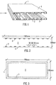
- a sound attenuating air vent 1 comprises an air path 2 extending between two vent openings, with a discontinuous sound absorbing lining placed around the air path 2.
- the preferred lining is made up of sound absorbing material in the form of strips 3 of melamine foam.
- the flow of air through the air path 2 is across the width of the strips 3 as shown by the arrow X in Figure 1 . Passage of sound through the air path 2 in the direction of arrow X is attenuated by the strips 3.
- Figure 1 is a perspective view that is cut-away through a longitudinal section of a vent and shows strips 3 applied with varying widths and varying spacings.
- the air path 2 is defined by an outer casing 4.
- Figure 2 shows a longitudinal cross-section through a similar vent, with casing 4 and strips 3.
- the strips 3 are evenly spaced instead of variably spaced as in Figure 1 .
- the strips 3 are of 50mm width at 100mm spacing, giving a period of 150mm.
- the strips are about 25mm in depth.
- Figure 2 also illustrates a typical length and depth for a vent. The length and cross-section of the vent are selected for attenuation properties and for the required passage of air for ventilation.
- the vent is 1500mm long and 300mm deep.
- Figure 3 is a transverse section through the vent.
- the casing 4 is rectangular in section forming a rectangular air path 2.
- the strips 3 are placed around the entire inner surface of the vent. As shown in Figure 3 , for a vent that is 300mm deep a typical width would be 750mm.
- the lining includes sound reflecting material between the areas of sound absorbing material.
- this feature is not shown, but could take the form of a strip or rib of a sound reflecting material (e.g. a dense plastic, or wood based board) located between the strips 3 of sound absorbing material.
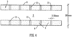
- Figure 4 gives an example of a vent including both sound absorbing material in strips 3, and sound reflecting material in ribs 11 between the strips.
- Figure 4 shows the most preferred arrangement where there are no gaps between the strips 3 and ribs 11.
- one possible set of dimensions uses a rib width of about 20mm, a strip width of about 130mm, and a thickness of about 50mm for both the ribs 11 and strips 3.
- vent 1, lining strips 3 and ribs 11 are not limited to these dimensions.
- Other sizes of vents 1 and other arrangements of strips 3 and ribs 11 can be selected based on the required acoustic and aerodynamic properties, and on the structure in which the vent/lining is to be installed.
- the table below sets out ranges of sizes for which the lining arrangements described herein are found to be particularly effective, although it should be noted that designs outside of these ranges may also find benefits in using the discontinuous lining.
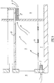
- Figure 5 gives an illustrated example of the use of first and second sound attenuating air vents 1', 1" being used for passive ventilation of a noise sensitive room 5.
- the room 5 is connected by a first vent 1' to the outside 6 for ventilation as in example (ii) above.
- the first vent 1' allows air to pass between the outside 6 and a floor void 7.
- This vent 1' is placed below floor level and is hence out of plane with the sound source, which would be outside, and/or the sound receiver, which would be in the room 5.
- the vent 1' would be designed for attenuation of undesirable sounds entering the building from the outside 6, such as traffic noise. Air can pass through the first vent 1' and the floor void 7 and into the noise sensitive room 5 via floor grilles 8. Arrows show the direction of air flow into the room 5.
- the second sound attenuating air vent 1" connects the room 5 to a circulation space 9 such as an atrium, enabling 'used' air from the room 5 to be vented to the circulation space 9 as in example (i) above.
- the second vent 1" is at ceiling level and in fact the upper wall surface of the vent 1" can be formed by the slab 10 of the floor above. As the vent 1" is at a high level it is out of plane with the sound receiver, in the room 5, and/or out of plane with the sound source in the circulation space 9.
- the second vent 1" could be designed for attenuation of sounds arising in the circulation space 9, such as background conversation noise. Arrows show the direction of air flow out of the room 5 and into the circulation space 9.
- the discontinuous lining can be supplied pre-installed in the vent 1, or the lining can be supplied separately, for example in the form of a roll of lining material that can be adhered to the casing 3 of the vent 1.
- this lining can be easily installed about the entirety of the vent 1 when the other walls of the vent 1 are formed.
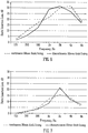
- Figures 6 and 7 are graphs showing the acoustic performance of linings having a thickness of 50mm and 20mm respectively. Frequency of the sound is shown on the horizontal axis and the vertical axis shows static insertion loss, which is a measure of attenuation.
- the dashed line 12 shows the performance of a conventional continuous layer of the sound absorbing material.
- the solid line 13 shows the performance of a discontinuous lining of the type illustrated in Figure 4 .
- discontinuous lining used 82mm wide strips of sound absorbing material and ribs formed of sound reflecting material 18mm wide, giving a period of 100mm for the discontinuity. Both the ribs and the strips had the same thickness, so as to present a continuous exposed surface in the vent.
- the discontinuous lining results in an increase in attenuation at certain frequencies.
- the period of discontinuity is 100mm which is a half-wavelength for frequencies of around 1.7kHz, and the graphs show improved attenuation at this frequency and nearby frequencies.
- the 50mm thick lining Figure 6 shows improved attenuation at a broad range of frequencies from about 700Hz to 2kHz, providing clear benefits.
- the 20mm lining Figure 7 shows increased attenuation about a higher range of frequencies.
- the discontinuous lining is aerodynamically similar to the conventional continuous lining of the same thickness.
- the discontinuous lining provides improved acoustic performance by increasing attenuation at selected frequencies whilst maintaining the aerodynamic performance of the conventional design. Varying the period of discontinuity and the thickness of the lining enables different frequencies to be targeted.
- a computer program product for designing a sound attenuating air vent and/or discontinuous lining can operate as follows.
- the computer program is graphic-orientated software that guides a user through the different steps of specifying a sound attenuating vent for their particular application. It starts with definition of noise source level, desired receiver noise level, constituent elements of the separating partition and the area of the vent required - this enables a target specification to be calculated.
- Other more detailed input information includes the position of source and receiver, and room details such as dimensions and surface finishes.
- the program will provide a summary page showing a typical elevation, section and detail, together with other more quantitative information. There is an option to listen to the sound transmission through the vent based on attenuation properties of the vent determined by the program - generic sound files will be made available for the most common room types.
- the main user interface comprises separate graphical objects that will serve as program input and output of data. Any suitable programming language or platform can be used for to generate the interface. Preferred platforms are Adobe FlashTM and Adobe Shockwave 3DTM.
- the interface will show the arrangement of the noise source, noise receiver and separating construction schematically based on data input by the user, and a 3D object representing the end product will also be shown
- Section - a 2D image that will update automatically as the user enters data.
- the image will be a generic cross-section along a line between noise source and noise receiver, comprising of two spaces separated by a partition wall.
- Typical parameters to be entered on this object via dropdown menus are: room/space size (I, w, h), room/space type, wall finishes and so on.
- the image is annotated by values set by the user and by values generated by the program. Further annotations could include images such as people.
- the elevation gets dynamically updated based on parameters entered. It shows the locations of vents, doors and windows. It also contains annotations, type and dimensions. There are options for the user to add/remove doors and windows.
- This object is dynamically updated based on parameters entered. Overlaid on top of this object will be annotations e.g. vent dimensions, a description of the sound absorbing lining and so on.
- the graphical objects for the section and elevation contain drop-down lists allowing the user to change parameters, which in-turn update all graphical objects. For example, if the user were to change an element of the separating construction from brick to plasterboard, the acoustic properties of the room will change and the vent/lining design 3D object is updated accordingly.
- information tables can be a combination of tables showing information. Some cells can be editable. Updating information in these cells will update the graphical objects described above. These tables could be expandable tabs i.e. a toggle between title and table, or any other suitable format.
- the user enters data into the program via dropdown menus and/or text input.
- the program also includes or has access to libraries on known pre-defined construction databases. For example, the program uses standard calculations and data relating to acoustic parameters to determine the acoustic properties of a space defined by the user by its dimensions and wall type. The various options available to the user are picked up by the program from a spreadsheet defining ranges of parameters for standard elements. This information is used by the program to generate drop-down lists, display appropriate titles to the user and know what multiplication factors to apply to the calculations.
- the output of the program is an image based on what is currently displayed on the screen. This can be saved to a number of image formats such as jpg, tiff, bmp etc.
- the program can also send this image to any connected printer. This simple output can be used for small or one-off installations or just as a visualisation tool for the end user. Additional outputs for use in more complex jobs or as input data for other systems or processes, such as an order setting out vents and lining materials required, take the form of spreadsheet files listing the components required and other parameters. For example the data included might number of vents, type, vent and/or lining details and so on.
- the program can also provide output sound files representing a simulation of sound at the receiver and at the source. This provides an indication of the acoustic performance of the vent/lining. The user can listen to simulations of noise transmitted by unlined vents or alternative vent constructions for comparison purposes.
- a design for a sound attenuating air vent or lining with desired acoustic and aerodynamic properties can hence be derived either based on the output from the computer program, or based on a manual design process using the principles discussed above.
Landscapes
- Engineering & Computer Science (AREA)
- General Engineering & Computer Science (AREA)
- Mechanical Engineering (AREA)
- Chemical & Material Sciences (AREA)
- Combustion & Propulsion (AREA)
- Physics & Mathematics (AREA)
- Acoustics & Sound (AREA)
- Architecture (AREA)
- Multimedia (AREA)
- Electromagnetism (AREA)
- Civil Engineering (AREA)
- Structural Engineering (AREA)
- Building Environments (AREA)
Claims (15)
- Schalldämpfende Belüftungsdüse für passive Belüftung zwischen zwei Bereichen eines Gebäudes oder zwischen einem Gebäude und dem Freien, wobei die Belüftungsdüse umfasst: einen Luftpfad (2), eine diskontinuierliche schallabsorbierende Verkleidung (3) um zumindest einen Teil des Luftpfads und schallreflektierendes Material (11) zwischen Bereichen der diskontinuierlichen schallabsorbierenden Verkleidung; wobei die diskontinuierliche schallabsorbierende Verkleidung Streifen aus schallabsorbierendem Material umfasst, die so in der Düse positioniert sind, dass sie im Allgemeinen senkrecht zur Richtung des Luftstroms und der Schallausbreitung sind;
dadurch gekennzeichnet, dass das schallreflektierende Material Rippen aus schallreflektierendem Material umfasst, die zwischen allen oder einigen der Streifen aus schallabsorbierendem Material vorgesehen sind, wobei die Rippen aus schallreflektierendem Material in der Breite dünner sind als die Streifen aus schallabsorbierendem Material und die Breitenrichtung der Streifen und der Rippen die Richtung des Luftstroms durch den Luftpfad ist. - Schalldämpfende Belüftungsdüse gemäß Anspruch 1, wobei das schallreflektierende Material (11) im Wesentlichen die Lücken zwischen der diskontinuierlichen schallabsorbierenden Verkleidung (3) füllt, sodass es dadurch eine im Wesentlichen kontinuierliche Verkleidung in der Düse bildet.
- Schalldämpfende Belüftungsdüse gemäß Anspruch 1 oder 2, wobei eine Periode der Diskontinuität der Streifen (3) und/oder Rippen (11) ausgewählt wird, die ungefähr eine halbe Wellenlänge der Basisfrequenz in einem zu dämpfenden Frequenzbereich beträgt.
- Schalldämpfende Belüftungsdüse gemäß einem der vorhergehenden Ansprüche, wobei die diskontinuierliche schallabsorbierende Verkleidung (3) so angeordnet ist, dass sie mehrere Perioden der Diskontinuität beinhaltet, die so ausgewählt wurden, dass sie einem gewünschten Satz von Frequenzen in einem zu dämpfenden Frequenzbereich entsprechen.
- Schalldämpfende Belüftungsdüse gemäß einem der vorhergehenden Ansprüche, wobei die Düse eine Form, Abmessungen und/oder diskontinuierliche Verkleidung (3) hat, die basierend auf einer Zielleistung ausgewählt wurden.
- Schalldämpfende Belüftungsdüse gemäß einem der vorhergehenden Ansprüche, Rippen aus schallreflektierendem Material (11) umfassend, die einstückig mit der Struktur der Düse gebildet sind.
- Verkleidung für eine schalldämpfende Belüftungsdüse für passive Belüftung zwischen zwei Bereichen eines Gebäudes oder zwischen einem Gebäude und dem Freien, wobei die Verkleidung umfasst: eine diskontinuierliche Schicht aus schallabsorbierendem Material (3) und schallreflektierendes Material (11) zwischen Bereichen des diskontinuierlichen schallabsorbierenden Materials; wobei das diskontinuierliche schallabsorbierende Material Streifen aus schallabsorbierendem Material umfasst, die dafür angepasst sind, so in der Düse positioniert zu werden, dass sie im Allgemeinen
senkrecht zur Richtung des Luftstroms und der Schallausbreitung sind; wobei das schallreflektierende Material Rippen aus schallreflektierendem Material umfasst, die zwischen allen oder einigen der Streifen aus schallabsorbierendem Material vorgesehen sind, und wobei die Rippen aus schallreflektierendem Material in der Breite dünner sind als die Streifen aus schallabsorbierendem Material und die Breitenrichtung der Streifen und der Rippen die Richtung des Luftstroms durch den Luftpfad ist. - Verkleidung gemäß Anspruch 7, umfassend eine Anordnung aus schallabsorbierendem Material (3) und/oder schallreflektierendem Material (11), wie in einem der Ansprüche 2 bis 6 beschrieben.
- Verkleidung gemäß Anspruch 7 oder 8, umfassend eine Trägerschicht, wobei das schallabsorbierende Material (3) auf der Trägerschicht montiert ist, um die diskontinuierliche Schicht aus schallabsorbierendem Material zu bilden.
- Abtrennung, die sich in Verwendung zwischen einer Schallquelle und einem Schallempfänger befindet, wobei die Abtrennung eine schalldämpfende Belüftungsdüse gemäß einem der Ansprüche 1 bis 6 und/oder eine Belüftungsdüse umfasst, die mit einer Verkleidung gemäß Anspruch 7, 8 oder 9 ausgekleidet ist, wobei die Düse so positioniert ist, dass sie nicht in einer Ebene mit der Schallquelle und oder dem Empfänger ist.
- Verfahren zu Bereitstellung einer schalldämpfenden Belüftungsdüse für passive Belüftung zwischen zwei Bereichen eines Gebäudes oder zwischen einem Gebäude und dem Freien, wobei das Verfahren umfasst:Bereitstellen einer diskontinuierlichen schallabsorbierenden Verkleidung (3) um zumindest einen Teil eines Luftpfads (2) durch die Belüftungsdüse, wobei die schallabsorbierende Verkleidung Streifen aus schallabsorbierendem Material umfasst, die so in der Düse positioniert sind, dass sie im Allgemeinen senkrecht zur Richtung des Luftstroms und der Schallausbreitung sind; undBereitstellen von schallreflektierendem Material (11) zwischen Bereichen aus schallabsorbierendem Material;dadurch gekennzeichnet, dass das schallreflektierende Material Rippen aus schallreflektierendem Material umfasst, die zwischen allen oder einigen der Streifen aus schallabsorbierendem Material vorgesehen sind, wobei die Rippen aus schallreflektierendem Material in der Breite dünner sind als die Streifen aus schallabsorbierendem Material und die Breitenrichtung der Streifen und der Rippen die Richtung des Luftstroms durch den Luftpfad ist.
- Verfahren gemäß Anspruch 11, umfassend das Anordnen der schalldämpfenden Belüftungsdüse, sodass sie nicht in einer Ebene mit der Schallquelle und oder dem Schallempfänger ist.
- Verfahren gemäß Anspruch 11 oder 12, umfassend das Formen von Wänden der Düsenstruktur mit Innenrippen aus schallreflektierendem Material (11).
- Verfahren gemäß Anspruch 11 oder 12, wobei die Verkleidung diskontinuierliche Elemente (3, 11) umfasst, die an einer Trägerschicht befestigt sind, und das Verfahren einen Schritt des Installierens der diskontinuierlichen Verkleidung durch Befestigen der Trägerschicht an einer Innenfläche der Düse umfasst.
- Verfahren gemäß einem der Ansprüche 11 bis 14, umfassend das Bereitstellen der Düse und/oder der Verkleidung (3, 11) mit Merkmalen gemäß einem der Ansprüche 1 bis 9, um dadurch eine Ziel-Schalldämpfungsleistung bereitzustellen, wobei die Ziel-Schalldämpfungsleistung basierend auf dem unerwünschten Geräusch an der Quelle, dem gewünschten Schallpegel am Empfänger und der Trennkonstruktion zwischen Quelle und Empfänger bestimmt wird.
Applications Claiming Priority (2)
| Application Number | Priority Date | Filing Date | Title |
|---|---|---|---|
| GBGB0915517.7A GB0915517D0 (en) | 2009-09-04 | 2009-09-04 | Sound attenuation air vent |
| PCT/GB2010/001672 WO2011027123A1 (en) | 2009-09-04 | 2010-09-03 | Sound attenuating air vent |
Publications (2)
| Publication Number | Publication Date |
|---|---|
| EP2473992A1 EP2473992A1 (de) | 2012-07-11 |
| EP2473992B1 true EP2473992B1 (de) | 2017-04-05 |
Family
ID=41203241
Family Applications (1)
| Application Number | Title | Priority Date | Filing Date |
|---|---|---|---|
| EP10754775.4A Not-in-force EP2473992B1 (de) | 2009-09-04 | 2010-09-03 | Schalldämpfende belüftungsdüse, schalldämpfende verkleidung und verfahren zur bereitstellung einer schalldämpfenden belüftungsdüse |
Country Status (4)
| Country | Link |
|---|---|
| US (1) | US8511426B2 (de) |
| EP (1) | EP2473992B1 (de) |
| GB (2) | GB0915517D0 (de) |
| WO (1) | WO2011027123A1 (de) |
Families Citing this family (14)
| Publication number | Priority date | Publication date | Assignee | Title |
|---|---|---|---|---|
| GB2493170B (en) * | 2011-07-26 | 2017-04-12 | Silentair Group Ltd | Improved air conditioning units |
| GB2493169A (en) * | 2011-07-26 | 2013-01-30 | Silentair Group Ltd | Sound insulated ducted unit and an air conditioner incorporating the same |
| US9169750B2 (en) * | 2013-08-17 | 2015-10-27 | ESI Energy Solutions, LLC. | Fluid flow noise mitigation structure and method |
| US9599124B2 (en) | 2014-04-02 | 2017-03-21 | Cnh Industrial Canada, Ltd. | Air diffuser for vacuum fan of planters |
| CN104500869A (zh) * | 2014-11-25 | 2015-04-08 | 南通四通林业机械制造安装有限公司 | 一种有降噪功能的干燥器风管 |
| US9546596B1 (en) * | 2015-09-16 | 2017-01-17 | General Electric Company | Silencer panel and system for having plastic perforated side wall and electrostatic particle removal |
| US10244662B2 (en) * | 2015-12-11 | 2019-03-26 | International Business Machines Corporation | Method and apparatus for acoustical noise reduction and distributed airflow |
| CA3079296A1 (en) * | 2017-10-18 | 2019-04-25 | Ramboll Denmark Contracting Aps | Acoustic shutter assembly |
| DE202018101452U1 (de) | 2018-03-15 | 2018-04-03 | Krantz Gmbh | Schallabsorbereinrichtung |
| US11421911B2 (en) * | 2018-08-22 | 2022-08-23 | Oneida Air Systems, Inc. | Modular stacking sound filter |
| EP3614066A1 (de) | 2018-08-22 | 2020-02-26 | Arup Ventures Limited | Öffenbare paneel-einheit |
| CN109163439A (zh) * | 2018-10-28 | 2019-01-08 | 扬州新扬通风设备有限公司 | 一种具有消声装置的通风座 |
| CN118168084B (zh) * | 2024-04-17 | 2026-02-24 | 西北工业大学 | 一种通风降噪除尘的管道复合结构 |
| CN119123213B (zh) * | 2024-10-28 | 2025-09-16 | 中国舰船研究设计中心 | 基于水下潜器内肋骨的消声结构风管 |
Family Cites Families (14)
| Publication number | Priority date | Publication date | Assignee | Title |
|---|---|---|---|---|
| US3207258A (en) * | 1964-03-17 | 1965-09-21 | Pittsburgh Corning Corp | Sound absorbing systems |
| DE2356184A1 (de) * | 1973-11-07 | 1975-05-15 | Johann Cieslik | In mehreren achsen flexibles material |
| US4104002A (en) * | 1976-12-02 | 1978-08-01 | General Electric Company | Spiral strip acoustic treatment |
| DE3220023C2 (de) * | 1982-05-27 | 1993-05-27 | Cellofoam Deutschland Gmbh, 7950 Biberach | Schalldämpfender Strömungskanal und Verfahren zu seiner Herstellung |
| US4645032A (en) * | 1985-09-05 | 1987-02-24 | The Garrett Corporation | Compact muffler apparatus and associated methods |
| US5728979A (en) * | 1993-04-05 | 1998-03-17 | Air Handling Engineering Ltd. | Air handling structure for fan inlet and outlet |
| WO1995006838A1 (en) * | 1993-08-31 | 1995-03-09 | E.I. Du Pont De Nemours And Company | Acoustically inactive corrugated structure |
| JP3275582B2 (ja) * | 1994-11-28 | 2002-04-15 | 日産自動車株式会社 | 吸音構造体 |
| US5728980A (en) * | 1995-04-21 | 1998-03-17 | Zarnick; Bernard | Duct silencer |
| US5679931A (en) * | 1995-07-10 | 1997-10-21 | Aaf-International | Sound attenuating apparatus and method of forming the same |
| DE19648200C2 (de) | 1995-11-23 | 2000-07-06 | Ltg Lufttechnische Gmbh | Luftleitung mit Rohrschalldämpfer |
| AUPO910697A0 (en) * | 1997-09-11 | 1997-10-02 | Hrl Technology Pty Ltd | Improved sound attenuating device |
| US6589112B2 (en) * | 2000-12-29 | 2003-07-08 | Evan Ruach | Duct silencer |
| DE50208072D1 (de) * | 2002-05-31 | 2006-10-19 | Siemens Ag | Schalldämpferanordnung für einen Strömungskanal, insbesondere für ein Ansaughaus einer Gasturbine |
-
2009
- 2009-09-04 GB GBGB0915517.7A patent/GB0915517D0/en not_active Ceased
-
2010
- 2010-09-03 EP EP10754775.4A patent/EP2473992B1/de not_active Not-in-force
- 2010-09-03 US US13/394,210 patent/US8511426B2/en not_active Expired - Fee Related
- 2010-09-03 GB GB1014763.5A patent/GB2473917B/en active Active
- 2010-09-03 WO PCT/GB2010/001672 patent/WO2011027123A1/en not_active Ceased
Non-Patent Citations (1)
| Title |
|---|
| None * |
Also Published As
| Publication number | Publication date |
|---|---|
| GB0915517D0 (en) | 2009-10-07 |
| GB201014763D0 (en) | 2010-10-20 |
| EP2473992A1 (de) | 2012-07-11 |
| US20120217088A1 (en) | 2012-08-30 |
| GB2473917A (en) | 2011-03-30 |
| GB2473917B (en) | 2014-12-10 |
| WO2011027123A1 (en) | 2011-03-10 |
| US8511426B2 (en) | 2013-08-20 |
Similar Documents
| Publication | Publication Date | Title |
|---|---|---|
| US8511426B2 (en) | Sound attenuating air vent | |
| JP6672391B2 (ja) | 消音システム | |
| EP3430323B1 (de) | Verfahren und vorrichtung zur akustischen rauschsteuerung von metamaterialien für kanalisierte systeme | |
| CN112534193B (zh) | 消声系统 | |
| WO2020036029A1 (ja) | 消音システム | |
| CN112069657B (zh) | 适用于气流环境下管道声衬设计方法及管道声衬 | |
| CN105373649A (zh) | 一种基于组合墙隔声理论的优化声学包的方法 | |
| JP2019056516A (ja) | 消音システム | |
| JP6672390B2 (ja) | 消音システム | |
| Sequeira et al. | Optimal acoustic design of multi-source industrial buildings by means of a simplified acoustic diffusion model | |
| JP2017101530A (ja) | 騒音低減構造 | |
| JP6196166B2 (ja) | 換気用のファンと消音チャンバとの組み合わせ性能のシミュレーション方法 | |
| Bibby et al. | Laboratory measurement of the acoustical and airflow performance of interior natural-ventilation openings and silencers | |
| EP4498361A1 (de) | Luftkanal mit schalldämpfer | |
| Li et al. | Scaled down measurement of HVAC duct insertion loss and comparison to simulation | |
| Herrin et al. | A review of prior ASHRAE research efforts to characterize noise propagation in ducts | |
| Ruan et al. | A Review of Prior Research on Assessing Insertion Loss and Breakout Transmission Loss of Ductwork | |
| JP2023061446A (ja) | 吸音材の設置量の算出方法及び算出装置 | |
| RU2789296C1 (ru) | Способ настройки частотных характеристик звукопоглощающих систем и материалов | |
| Wójciak et al. | Correlation between the shape of substitution ducts and insertion loss of silencers | |
| Li et al. | Utilization of microperforated panel parallel baffle silencers for noise reduction in ducts | |
| Li | Ramifications of Adding a Thin Protective Layer to Fiber Lining on Duct Insertion Loss | |
| EP4498362A1 (de) | Luftkanal mit schalldämpfer | |
| David et al. | Sound insulation of flow-permeable biomimetic honeycomb structures with Helmholtz resonators | |
| JP7650655B2 (ja) | ふかし壁構造 |
Legal Events
| Date | Code | Title | Description |
|---|---|---|---|
| PUAI | Public reference made under article 153(3) epc to a published international application that has entered the european phase |
Free format text: ORIGINAL CODE: 0009012 |
|
| 17P | Request for examination filed |
Effective date: 20120312 |
|
| AK | Designated contracting states |
Kind code of ref document: A1 Designated state(s): AL AT BE BG CH CY CZ DE DK EE ES FI FR GB GR HR HU IE IS IT LI LT LU LV MC MK MT NL NO PL PT RO SE SI SK SM TR |
|
| DAX | Request for extension of the european patent (deleted) | ||
| 17Q | First examination report despatched |
Effective date: 20150917 |
|
| GRAP | Despatch of communication of intention to grant a patent |
Free format text: ORIGINAL CODE: EPIDOSNIGR1 |
|
| RIC1 | Information provided on ipc code assigned before grant |
Ipc: F24F 13/02 20060101ALI20160928BHEP Ipc: F24F 13/24 20060101ALI20160928BHEP Ipc: G10K 11/16 20060101AFI20160928BHEP Ipc: F16L 55/033 20060101ALI20160928BHEP Ipc: F16L 9/21 20060101ALI20160928BHEP |
|
| INTG | Intention to grant announced |
Effective date: 20161103 |
|
| GRAS | Grant fee paid |
Free format text: ORIGINAL CODE: EPIDOSNIGR3 |
|
| GRAA | (expected) grant |
Free format text: ORIGINAL CODE: 0009210 |
|
| RBV | Designated contracting states (corrected) |
Designated state(s): AL AT BE BG CH CY CZ DE DK EE ES FI FR GR HR HU IE IS IT LI LT LU LV MC MK MT NL NO PL PT RO SE SI SK SM TR |
|
| AK | Designated contracting states |
Kind code of ref document: B1 Designated state(s): AL AT BE BG CH CY CZ DE DK EE ES FI FR GR HR HU IE IS IT LI LT LU LV MC MK MT NL NO PL PT RO SE SI SK SM TR |
|
| REG | Reference to a national code |
Ref country code: CH Ref legal event code: EP |
|
| REG | Reference to a national code |
Ref country code: AT Ref legal event code: REF Ref document number: 882469 Country of ref document: AT Kind code of ref document: T Effective date: 20170415 |
|
| REG | Reference to a national code |
Ref country code: IE Ref legal event code: FG4D |
|
| REG | Reference to a national code |
Ref country code: DE Ref legal event code: R096 Ref document number: 602010041313 Country of ref document: DE |
|
| REG | Reference to a national code |
Ref country code: NL Ref legal event code: MP Effective date: 20170405 |
|
| REG | Reference to a national code |
Ref country code: LT Ref legal event code: MG4D |
|
| REG | Reference to a national code |
Ref country code: AT Ref legal event code: MK05 Ref document number: 882469 Country of ref document: AT Kind code of ref document: T Effective date: 20170405 |
|
| REG | Reference to a national code |
Ref country code: FR Ref legal event code: PLFP Year of fee payment: 8 |
|
| PG25 | Lapsed in a contracting state [announced via postgrant information from national office to epo] |
Ref country code: NL Free format text: LAPSE BECAUSE OF FAILURE TO SUBMIT A TRANSLATION OF THE DESCRIPTION OR TO PAY THE FEE WITHIN THE PRESCRIBED TIME-LIMIT Effective date: 20170405 |
|
| PG25 | Lapsed in a contracting state [announced via postgrant information from national office to epo] |
Ref country code: FI Free format text: LAPSE BECAUSE OF FAILURE TO SUBMIT A TRANSLATION OF THE DESCRIPTION OR TO PAY THE FEE WITHIN THE PRESCRIBED TIME-LIMIT Effective date: 20170405 Ref country code: NO Free format text: LAPSE BECAUSE OF FAILURE TO SUBMIT A TRANSLATION OF THE DESCRIPTION OR TO PAY THE FEE WITHIN THE PRESCRIBED TIME-LIMIT Effective date: 20170705 Ref country code: LT Free format text: LAPSE BECAUSE OF FAILURE TO SUBMIT A TRANSLATION OF THE DESCRIPTION OR TO PAY THE FEE WITHIN THE PRESCRIBED TIME-LIMIT Effective date: 20170405 Ref country code: HR Free format text: LAPSE BECAUSE OF FAILURE TO SUBMIT A TRANSLATION OF THE DESCRIPTION OR TO PAY THE FEE WITHIN THE PRESCRIBED TIME-LIMIT Effective date: 20170405 Ref country code: ES Free format text: LAPSE BECAUSE OF FAILURE TO SUBMIT A TRANSLATION OF THE DESCRIPTION OR TO PAY THE FEE WITHIN THE PRESCRIBED TIME-LIMIT Effective date: 20170405 Ref country code: AT Free format text: LAPSE BECAUSE OF FAILURE TO SUBMIT A TRANSLATION OF THE DESCRIPTION OR TO PAY THE FEE WITHIN THE PRESCRIBED TIME-LIMIT Effective date: 20170405 Ref country code: GR Free format text: LAPSE BECAUSE OF FAILURE TO SUBMIT A TRANSLATION OF THE DESCRIPTION OR TO PAY THE FEE WITHIN THE PRESCRIBED TIME-LIMIT Effective date: 20170706 |
|
| PG25 | Lapsed in a contracting state [announced via postgrant information from national office to epo] |
Ref country code: BG Free format text: LAPSE BECAUSE OF FAILURE TO SUBMIT A TRANSLATION OF THE DESCRIPTION OR TO PAY THE FEE WITHIN THE PRESCRIBED TIME-LIMIT Effective date: 20170705 Ref country code: LV Free format text: LAPSE BECAUSE OF FAILURE TO SUBMIT A TRANSLATION OF THE DESCRIPTION OR TO PAY THE FEE WITHIN THE PRESCRIBED TIME-LIMIT Effective date: 20170405 Ref country code: SE Free format text: LAPSE BECAUSE OF FAILURE TO SUBMIT A TRANSLATION OF THE DESCRIPTION OR TO PAY THE FEE WITHIN THE PRESCRIBED TIME-LIMIT Effective date: 20170405 Ref country code: PL Free format text: LAPSE BECAUSE OF FAILURE TO SUBMIT A TRANSLATION OF THE DESCRIPTION OR TO PAY THE FEE WITHIN THE PRESCRIBED TIME-LIMIT Effective date: 20170405 Ref country code: IS Free format text: LAPSE BECAUSE OF FAILURE TO SUBMIT A TRANSLATION OF THE DESCRIPTION OR TO PAY THE FEE WITHIN THE PRESCRIBED TIME-LIMIT Effective date: 20170805 |
|
| REG | Reference to a national code |
Ref country code: DE Ref legal event code: R097 Ref document number: 602010041313 Country of ref document: DE |
|
| RAP2 | Party data changed (patent owner data changed or rights of a patent transferred) |
Owner name: ARUP VENTURES LIMITED |
|
| PG25 | Lapsed in a contracting state [announced via postgrant information from national office to epo] |
Ref country code: EE Free format text: LAPSE BECAUSE OF FAILURE TO SUBMIT A TRANSLATION OF THE DESCRIPTION OR TO PAY THE FEE WITHIN THE PRESCRIBED TIME-LIMIT Effective date: 20170405 Ref country code: DK Free format text: LAPSE BECAUSE OF FAILURE TO SUBMIT A TRANSLATION OF THE DESCRIPTION OR TO PAY THE FEE WITHIN THE PRESCRIBED TIME-LIMIT Effective date: 20170405 Ref country code: SK Free format text: LAPSE BECAUSE OF FAILURE TO SUBMIT A TRANSLATION OF THE DESCRIPTION OR TO PAY THE FEE WITHIN THE PRESCRIBED TIME-LIMIT Effective date: 20170405 Ref country code: RO Free format text: LAPSE BECAUSE OF FAILURE TO SUBMIT A TRANSLATION OF THE DESCRIPTION OR TO PAY THE FEE WITHIN THE PRESCRIBED TIME-LIMIT Effective date: 20170405 Ref country code: CZ Free format text: LAPSE BECAUSE OF FAILURE TO SUBMIT A TRANSLATION OF THE DESCRIPTION OR TO PAY THE FEE WITHIN THE PRESCRIBED TIME-LIMIT Effective date: 20170405 |
|
| PLBE | No opposition filed within time limit |
Free format text: ORIGINAL CODE: 0009261 |
|
| STAA | Information on the status of an ep patent application or granted ep patent |
Free format text: STATUS: NO OPPOSITION FILED WITHIN TIME LIMIT |
|
| REG | Reference to a national code |
Ref country code: BE Ref legal event code: PD Owner name: ARUP VENTURES LIMITED; GB Free format text: DETAILS ASSIGNMENT: CHANGE OF OWNER(S), AFFECTATION / CESSION; FORMER OWNER NAME: OVE ARUP&PARTNERS INTERNATIONAL LTD Effective date: 20171031 |
|
| PG25 | Lapsed in a contracting state [announced via postgrant information from national office to epo] |
Ref country code: IT Free format text: LAPSE BECAUSE OF FAILURE TO SUBMIT A TRANSLATION OF THE DESCRIPTION OR TO PAY THE FEE WITHIN THE PRESCRIBED TIME-LIMIT Effective date: 20170405 Ref country code: SM Free format text: LAPSE BECAUSE OF FAILURE TO SUBMIT A TRANSLATION OF THE DESCRIPTION OR TO PAY THE FEE WITHIN THE PRESCRIBED TIME-LIMIT Effective date: 20170405 |
|
| 26N | No opposition filed |
Effective date: 20180108 |
|
| REG | Reference to a national code |
Ref country code: DE Ref legal event code: R082 Ref document number: 602010041313 Country of ref document: DE Representative=s name: DREISS PATENTANWAELTE PARTG MBB, DE Ref country code: DE Ref legal event code: R081 Ref document number: 602010041313 Country of ref document: DE Owner name: ARUP VENTURES LIMITED, GB Free format text: FORMER OWNER: OVE ARUP&PARTNERS INTERNATIONAL LTD, LONDON, GB |
|
| REG | Reference to a national code |
Ref country code: CH Ref legal event code: PL |
|
| PG25 | Lapsed in a contracting state [announced via postgrant information from national office to epo] |
Ref country code: MC Free format text: LAPSE BECAUSE OF FAILURE TO SUBMIT A TRANSLATION OF THE DESCRIPTION OR TO PAY THE FEE WITHIN THE PRESCRIBED TIME-LIMIT Effective date: 20170405 Ref country code: SI Free format text: LAPSE BECAUSE OF FAILURE TO SUBMIT A TRANSLATION OF THE DESCRIPTION OR TO PAY THE FEE WITHIN THE PRESCRIBED TIME-LIMIT Effective date: 20170405 |
|
| PG25 | Lapsed in a contracting state [announced via postgrant information from national office to epo] |
Ref country code: LU Free format text: LAPSE BECAUSE OF NON-PAYMENT OF DUE FEES Effective date: 20170903 |
|
| PG25 | Lapsed in a contracting state [announced via postgrant information from national office to epo] |
Ref country code: LI Free format text: LAPSE BECAUSE OF NON-PAYMENT OF DUE FEES Effective date: 20170930 Ref country code: CH Free format text: LAPSE BECAUSE OF NON-PAYMENT OF DUE FEES Effective date: 20170930 |
|
| PG25 | Lapsed in a contracting state [announced via postgrant information from national office to epo] |
Ref country code: MT Free format text: LAPSE BECAUSE OF NON-PAYMENT OF DUE FEES Effective date: 20170903 |
|
| REG | Reference to a national code |
Ref country code: FR Ref legal event code: PLFP Year of fee payment: 9 |
|
| PG25 | Lapsed in a contracting state [announced via postgrant information from national office to epo] |
Ref country code: HU Free format text: LAPSE BECAUSE OF FAILURE TO SUBMIT A TRANSLATION OF THE DESCRIPTION OR TO PAY THE FEE WITHIN THE PRESCRIBED TIME-LIMIT; INVALID AB INITIO Effective date: 20100903 |
|
| PG25 | Lapsed in a contracting state [announced via postgrant information from national office to epo] |
Ref country code: CY Free format text: LAPSE BECAUSE OF NON-PAYMENT OF DUE FEES Effective date: 20170405 |
|
| PG25 | Lapsed in a contracting state [announced via postgrant information from national office to epo] |
Ref country code: MK Free format text: LAPSE BECAUSE OF FAILURE TO SUBMIT A TRANSLATION OF THE DESCRIPTION OR TO PAY THE FEE WITHIN THE PRESCRIBED TIME-LIMIT Effective date: 20170405 |
|
| PG25 | Lapsed in a contracting state [announced via postgrant information from national office to epo] |
Ref country code: TR Free format text: LAPSE BECAUSE OF FAILURE TO SUBMIT A TRANSLATION OF THE DESCRIPTION OR TO PAY THE FEE WITHIN THE PRESCRIBED TIME-LIMIT Effective date: 20170405 |
|
| PG25 | Lapsed in a contracting state [announced via postgrant information from national office to epo] |
Ref country code: PT Free format text: LAPSE BECAUSE OF FAILURE TO SUBMIT A TRANSLATION OF THE DESCRIPTION OR TO PAY THE FEE WITHIN THE PRESCRIBED TIME-LIMIT Effective date: 20170405 |
|
| PG25 | Lapsed in a contracting state [announced via postgrant information from national office to epo] |
Ref country code: AL Free format text: LAPSE BECAUSE OF FAILURE TO SUBMIT A TRANSLATION OF THE DESCRIPTION OR TO PAY THE FEE WITHIN THE PRESCRIBED TIME-LIMIT Effective date: 20170405 |
|
| PGFP | Annual fee paid to national office [announced via postgrant information from national office to epo] |
Ref country code: FR Payment date: 20200929 Year of fee payment: 11 |
|
| PGFP | Annual fee paid to national office [announced via postgrant information from national office to epo] |
Ref country code: BE Payment date: 20200928 Year of fee payment: 11 |
|
| PGFP | Annual fee paid to national office [announced via postgrant information from national office to epo] |
Ref country code: DE Payment date: 20201116 Year of fee payment: 11 |
|
| PGFP | Annual fee paid to national office [announced via postgrant information from national office to epo] |
Ref country code: IE Payment date: 20210820 Year of fee payment: 12 |
|
| REG | Reference to a national code |
Ref country code: DE Ref legal event code: R119 Ref document number: 602010041313 Country of ref document: DE |
|
| REG | Reference to a national code |
Ref country code: BE Ref legal event code: MM Effective date: 20210930 |
|
| PG25 | Lapsed in a contracting state [announced via postgrant information from national office to epo] |
Ref country code: FR Free format text: LAPSE BECAUSE OF NON-PAYMENT OF DUE FEES Effective date: 20210930 Ref country code: DE Free format text: LAPSE BECAUSE OF NON-PAYMENT OF DUE FEES Effective date: 20220401 Ref country code: BE Free format text: LAPSE BECAUSE OF NON-PAYMENT OF DUE FEES Effective date: 20210930 |
|
| PG25 | Lapsed in a contracting state [announced via postgrant information from national office to epo] |
Ref country code: IE Free format text: LAPSE BECAUSE OF NON-PAYMENT OF DUE FEES Effective date: 20220903 |