EP2473828B1 - Flexible deep tissue temperature measurement devices - Google Patents
Flexible deep tissue temperature measurement devices Download PDFInfo
- Publication number
- EP2473828B1 EP2473828B1 EP10743259.3A EP10743259A EP2473828B1 EP 2473828 B1 EP2473828 B1 EP 2473828B1 EP 10743259 A EP10743259 A EP 10743259A EP 2473828 B1 EP2473828 B1 EP 2473828B1
- Authority
- EP
- European Patent Office
- Prior art keywords
- disposed
- heater
- flexible
- temperature
- center section
- Prior art date
- Legal status (The legal status is an assumption and is not a legal conclusion. Google has not performed a legal analysis and makes no representation as to the accuracy of the status listed.)
- Active
Links
- 238000009529 body temperature measurement Methods 0.000 title description 29
- 239000000758 substrate Substances 0.000 claims description 54
- 239000012212 insulator Substances 0.000 claims description 13
- 239000003351 stiffener Substances 0.000 claims description 12
- 238000005259 measurement Methods 0.000 description 15
- 238000004519 manufacturing process Methods 0.000 description 14
- 238000010276 construction Methods 0.000 description 9
- 230000004907 flux Effects 0.000 description 9
- 238000000034 method Methods 0.000 description 8
- 238000009413 insulation Methods 0.000 description 6
- 239000000853 adhesive Substances 0.000 description 5
- 230000001070 adhesive effect Effects 0.000 description 5
- 239000011810 insulating material Substances 0.000 description 5
- 239000000463 material Substances 0.000 description 5
- 238000012544 monitoring process Methods 0.000 description 3
- RYGMFSIKBFXOCR-UHFFFAOYSA-N Copper Chemical compound [Cu] RYGMFSIKBFXOCR-UHFFFAOYSA-N 0.000 description 2
- 241001465754 Metazoa Species 0.000 description 2
- 239000004820 Pressure-sensitive adhesive Substances 0.000 description 2
- XAGFODPZIPBFFR-UHFFFAOYSA-N aluminium Chemical compound [Al] XAGFODPZIPBFFR-UHFFFAOYSA-N 0.000 description 2
- 229910052782 aluminium Inorganic materials 0.000 description 2
- 230000008901 benefit Effects 0.000 description 2
- 229910052802 copper Inorganic materials 0.000 description 2
- 239000010949 copper Substances 0.000 description 2
- 238000013461 design Methods 0.000 description 2
- 238000010586 diagram Methods 0.000 description 2
- -1 polyethylene Polymers 0.000 description 2
- 229920000139 polyethylene terephthalate Polymers 0.000 description 2
- 239000005020 polyethylene terephthalate Substances 0.000 description 2
- 230000002787 reinforcement Effects 0.000 description 2
- 239000004698 Polyethylene Substances 0.000 description 1
- 241001290266 Sciaenops ocellatus Species 0.000 description 1
- 208000031650 Surgical Wound Infection Diseases 0.000 description 1
- 230000004913 activation Effects 0.000 description 1
- 239000002313 adhesive film Substances 0.000 description 1
- 230000000712 assembly Effects 0.000 description 1
- 238000000429 assembly Methods 0.000 description 1
- 230000009286 beneficial effect Effects 0.000 description 1
- 230000017531 blood circulation Effects 0.000 description 1
- 230000036760 body temperature Effects 0.000 description 1
- 230000036757 core body temperature Effects 0.000 description 1
- 238000012864 cross contamination Methods 0.000 description 1
- 230000002500 effect on skin Effects 0.000 description 1
- 239000006260 foam Substances 0.000 description 1
- 238000012423 maintenance Methods 0.000 description 1
- 238000001259 photo etching Methods 0.000 description 1
- 229920003223 poly(pyromellitimide-1,4-diphenyl ether) Polymers 0.000 description 1
- 229920000573 polyethylene Polymers 0.000 description 1
- 229920001721 polyimide Polymers 0.000 description 1
- 230000000284 resting effect Effects 0.000 description 1
- 238000011012 sanitization Methods 0.000 description 1
- 238000001356 surgical procedure Methods 0.000 description 1
- 238000012546 transfer Methods 0.000 description 1
- 230000001052 transient effect Effects 0.000 description 1
Images


Classifications
-
- G—PHYSICS
- G01—MEASURING; TESTING
- G01K—MEASURING TEMPERATURE; MEASURING QUANTITY OF HEAT; THERMALLY-SENSITIVE ELEMENTS NOT OTHERWISE PROVIDED FOR
- G01K1/00—Details of thermometers not specially adapted for particular types of thermometer
- G01K1/16—Special arrangements for conducting heat from the object to the sensitive element
- G01K1/165—Special arrangements for conducting heat from the object to the sensitive element for application in zero heat flux sensors
-
- A—HUMAN NECESSITIES
- A61—MEDICAL OR VETERINARY SCIENCE; HYGIENE
- A61B—DIAGNOSIS; SURGERY; IDENTIFICATION
- A61B5/00—Measuring for diagnostic purposes; Identification of persons
- A61B5/01—Measuring temperature of body parts ; Diagnostic temperature sensing, e.g. for malignant or inflamed tissue
-
- G—PHYSICS
- G01—MEASURING; TESTING
- G01K—MEASURING TEMPERATURE; MEASURING QUANTITY OF HEAT; THERMALLY-SENSITIVE ELEMENTS NOT OTHERWISE PROVIDED FOR
- G01K13/00—Thermometers specially adapted for specific purposes
- G01K13/20—Clinical contact thermometers for use with humans or animals
-
- A—HUMAN NECESSITIES
- A61—MEDICAL OR VETERINARY SCIENCE; HYGIENE
- A61B—DIAGNOSIS; SURGERY; IDENTIFICATION
- A61B2562/00—Details of sensors; Constructional details of sensor housings or probes; Accessories for sensors
- A61B2562/12—Manufacturing methods specially adapted for producing sensors for in-vivo measurements
-
- Y—GENERAL TAGGING OF NEW TECHNOLOGICAL DEVELOPMENTS; GENERAL TAGGING OF CROSS-SECTIONAL TECHNOLOGIES SPANNING OVER SEVERAL SECTIONS OF THE IPC; TECHNICAL SUBJECTS COVERED BY FORMER USPC CROSS-REFERENCE ART COLLECTIONS [XRACs] AND DIGESTS
- Y10—TECHNICAL SUBJECTS COVERED BY FORMER USPC
- Y10T—TECHNICAL SUBJECTS COVERED BY FORMER US CLASSIFICATION
- Y10T29/00—Metal working
- Y10T29/49—Method of mechanical manufacture
- Y10T29/49002—Electrical device making
- Y10T29/49117—Conductor or circuit manufacturing
Definitions
- the subject matter relates to a device for use in the estimation of deep tissue temperature (DTT), a temperature of human or animal tissue at some distance beneath the skin.
- DTT deep tissue temperature
- the core temperature of a human body can be measured indirectly using a disposable temperature device placed on surface tissue (such as skin). The temperature of the surface tissue is read as the core temperature.
- Noninvasive measurement of deep tissue temperature by means of a zero-heat-flux device was described by Fox and Solman in 1971 ( Fox RH, Solman AJ. A new technique for monitoring the deep body temperature in man from the intact skin surface. J. Physiol. Jan 1971:212(2): pp 8-10 ).
- the Fox/Solman system illustrated in FIG. 1 , estimates body core temperature by indirect means using a specially designed measurement device 10 that stops or blocks heat flow through a portion of the skin.
- the components of the device 10 are contained in a housing 11.
- the device 10 includes two thermistors 20 mounted on either side of a thermal resistance 22.
- the thermal resistance 22 maintains the thermistors in a spaced-apart arrangement in which the thermistors are positioned on separate sides of the thermal resistance, along a line that is generally perpendicular to a region of skin on a person's body where deep tissue temperature is to be measured.
- a heater 24 is disposed at the top of the device 10, over the elements 20, 22, and 24. In use, the device 10 is placed on the region of skin. With the bottom surface 26 of the device resting on the person's body, in contact with the region, the thermistors 20 measure a temperature difference, or error signal, across the thermal resistance 22.
- the error signal is used to drive a heater controller 30 comprising a transistor switch and a control circuit for opening and closing the switch.
- the controller 30 operates to minimize the error signal by causing the heater 24 to provide just enough heat to equalize the temperature on both sides of the thermal resistance 22.
- the device 10 essentially acts as a thermal insulator that blocks heat flow through the thermal resistor 22; DTT measurement devices that operate in the same manner are termed "zero heat flux" (“ZHF”) devices. Since the heater 24 operates to guard against loss of heat along the path of measurement through the device, it is often referred to as a "guard heater".
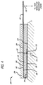
- the device, illustrated in FIG. 2 encloses Fox and Solman's ZHF design, which blocks heat flow normal to the body, in a thick aluminum housing with a cylindrical annulus construction that also reduces or eliminates radial heat flow from the center to the periphery of the device.
- Measurement of body core temperature is desirable for many reasons. For example, maintenance of core temperature in a normothermic range during a perioperative cycle has been shown to reduce the incidence of surgical site infection; and so it is beneficial to monitor a patient's body core temperature before, during, and after surgery. Of course noninvasive measurement is very desirable, for the comfort and the safety of a patient. Deep tissue temperature measurement using a measurement device supported on the skin provides an accurate and noninvasive means for monitoring body core temperature.
- the size and mass and cost of the Fox/Solman and Togawa devices do not promote disposability. Consequently, they must be sanitized after each use, and stored for reuse.
- An object of an invention completed in respect of the problems described above is to provide a disposable device as defined in claim 1, with which deep tissue temperature can be measured noninvasively, easily, and with minimal labor, length of time, and cost.
- the object is achieved with a disposable temperature measurement device constituted of a flexible substrate and an electrical circuit disposed on a surface of the flexible substrate.
- the electrical circuit includes a heater trace having a pattern surrounding a zone of the surface, a first thermal sensor disposed in the zone, a second thermal sensor disposed outside of the heater trace, a plurality of electrical pads disposed outside of the heater trace, and a plurality of conductive traces connecting the first and second thermal sensors and the heater trace with the plurality of electrical pads. Sections of the flexible substrate are folded together to place the first and second thermal sensors in proximity.
- the temperature measurement device preferably includes a layer of flexible insulation disposed between the folded-together sections and separating the first and second thermal sensors
- a pattern of slits in the flexible substrate defines a plurality of heater zones occupied by the heater trace.
- each heater zone is flexible independently of any other heater zone.
- a disposable temperature measurement device constituted of a flexible substrate having first and second sides.
- the flexible substrate includes a circular center section and a tab and a tail extending from the center section in respective radial directions.
- a first thermal sensor is disposed on a first substrate side, substantially at the center of the center section, and a heater trace is disposed on the first substrate side, in the center section, around the first thermal sensor.
- a second thermal sensor is disposed on the first side, in the tail. The center section and the tail are folded together to place the first and second thermal sensors in proximity to each other, and a layer of flexible insulation disposed between the folded-together center section and tail maintains the first and second thermal sensors in a spaced-apart relationship.
- a plurality of electrical pads is disposed on the first substrate side, in the tab, and a plurality of traces is disposed on the first side to connect the first and second thermal sensors and the heater trace with the plurality of electrical pads.
- the object is also achieved with a method of temperature device manufacture that includes fabricating an electrical circuit on a first side of a flexible substrate with a center section, a tab extending from the center section, and a tail extending from the center section.
- the electrical circuit includes a first thermal sensor disposed on the first side, in the center section, a heater trace disposed on the first side, in the center section, around the first thermal sensor, a second thermal sensor disposed on the first side, in the tail, a plurality of electrical pads disposed on the first side, in the tab, and a plurality of traces disposed on the first side and connecting the first and second thermal sensors and the heater trace with the plurality of electrical pads.
- a flexible heater insulating layer is attached to the second side, over the center section, and a flexible central insulating layer is attached to the first side, over the center section.
- the tail is folded over the central insulating layer such that the first and second thermal sensors are maintained in a spaced relationship by the central insulating layer.
- a release liner is attached to the central insulating layer, over at least the central insulating layer.
- zero heat flux, deep tissue temperature measurement device constructions be disposable.
- the constructions should be easy and inexpensive to fabricate and assemble, have a low mass and a low profile, and comprise inexpensive materials and parts.
- disposable DTT measurement device constructions be assembled from low-profile, light weight, flexible assemblies that enable zero heat flux temperature measurement at various locations on a human or animal body.
- a temperature device for zero heat flux deep tissue temperature measurement includes a flexible substrate with at least two thermal sensors disposed in a spaced-apart relationship and separated by one or more flexible layers of thermally insulating material. Preferably the sensors are maintained in a spaced apart relationship by a flexible thermal (and electrical) insulator.
- the substrate supports at least the thermal sensors, the separating thermal insulator, and a heater.
- temperature device constructions are described in terms of preferred embodiments comprising representative elements, the embodiments are merely illustrative. It is possible that other embodiments will include more elements, or fewer, than described. It is also possible that some of the described elements will be deleted, and/or other elements that are not described will be added. Further, elements may be combined with other elements, and/or partitioned into additional elements.
- FIG. 3 A layout of an electrical circuit for a temperature measurement device is illustrated in FIG. 3 .
- the electrical circuit is disposed on a flexible substrate in order to adapt or conform the physical configuration of the temperature measurement device to differing contours encountered at different temperature measurement locations.
- the flexible substrate is constructed or fabricated to have a plurality of contiguous sections.
- the flexible substrate 100 has three contiguous sections 102, 104, and 106.
- the first, or center, section 102 is substantially circular in shape.
- the second section (or "tail") 104 has the shape of a narrow, elongate rectangle that extends in a first radial direction from the periphery of the first section 102.
- the periphery of the center section has a straight portion and the width of the tail is reduced.
- the third, or tab, section 106 has the shape of a broad, elongate rectangle that extends in a second radial direction from the periphery of the center section 102.
- the tail and tab are aligned along a diameter of the center section.
- the elements of the electronic circuit are disposed on a single surface, on a first side 108 of the flexible substrate.
- a first thermal sensor 120 is positioned inside the outer perimeter of the center section 102, preferably, near or at the center of the center section 102.
- An electrically conductive heater trace 122 defines a heater with a shape that surrounds or encircles a zone 121 in which the first thermal sensor 120 is located.
- the heater trace has an annular shape that includes a circular array of wedge-shaped heater zones 124 that surround or encircle the zone 121 and the first thermal sensor 120 which is disposed in the zone.
- a second thermal sensor 126 is positioned on the tail 104.
- a plurality of electrical connection pads 130 is located in the tab 106.
- the heater trace includes two electrically conductive trace sections that terminate in the connection pads 130a and 130b. Two electrically conductive traces extend between mounting pads on which the first thermal sensor 120 is mounted and the connection pads 130c and 130d. Two additional electrically conductive traces extend between mounting pads on which the second thermal sensor 126 is mounted and the connection pads 130e and 130f.
- the path of the heater trace 122 crosses the paths of the two traces for the second thermal sensor 126.
- the continuity of the heater trace is preferably, but not necessarily, maintained by an electrically conductive zero-ohm jumper 132 which crosses, and is electrically isolated from, the two traces for the second thermal sensor 126.
- the continuity of the heater trace 122 can also be maintained by vias to the second side of the flexible substrate, by running the thermal sensor traces around the periphery of the first side of the flexible substrate, by a jumper wire instead of the zero-ohm resistor, or by any equivalent solution.
- the flexibility or conformability of the flexible substrate can be enhanced by a plurality of slits 133 that define zones which move or flex independently of each other.
- the slits 133 are made in the center section 102 in a pattern that follows or accommodates the layout of the heater trace 122.
- the pattern at least partially separates the heater zones 124 so as to allow any one of the heater zones 124 to move independently of any other heater zone.
- the preferred pattern of slits is a radial pattern in that each slit is made along a respective radius of the circular center section 102, between adjacent heater zones, and extends along the radius from the periphery of the center section 102 toward the center of the circular shape of the section. This is not meant to exclude other possible slit configurations determined by the different shapes of the heater trace layout and the flexible substrate sections.
- Sections of the flexible substrate are brought or folded together about an insulator to provide thermal resistance between the first and second thermal sensors 120 and 126 in a configuration that is preferred for ZHF temperature measurement.
- at least the center and tail sections 102 and 104 of the flexible substrate are brought or folded together about a flexible insulator.
- the first and second thermal sensors 120 and 126 are thereby disposed on respective sides of a thermal insulator.
- the center section 102 and tail 104 are folded together about a flexible layer of insulating material 140.
- the layer 140 provides thermal and electrical resistance between the thermal sensors; it also supports the thermal sensors in a spaced-apart configuration.
- a flexible temperature measurement device construction includes an electrical circuit laid out on a side of a flexible substrate as shown in FIG. 3 . With two sections of the flexible substrate brought or folded together so as to sandwich a flexible insulator, the construction has a multilayer structure as best seen in FIG. 4 .
- a temperature measurement device 200 includes the electrical circuit laid out on the surface of the first side 108 of the flexible substrate 100.
- the central and tail sections 102 and 104 are brought or folded together about the flexible insulating layer 140 so as to provide a thermal resistance between the first and second thermal sensors 120 and 126.
- the flexible insulating layer also maintains the first and second thermal sensors disposed in a spaced relationship.
- the second thermal sensor 126 is aligned with the first thermal sensor a line 202 which passes through the zone 121 that is surrounded by the heater trace (seen in FIG. 3 ).
- the temperature measurement device further includes a flexible heater insulator 208 attached to a second side 109 of the substrate 100, over the center section 102.
- the layout of the electrical circuit illustrated in FIG. 3 locates all of the circuit components on a single surface on one side of the flexible substrate 100. This layout confers several advantages. First, it requires only a single fabrication sequence to lay down traces for the heater, the thermal sensors, and the connection pads, thereby simplifying manufacture of the device. Second, when the sections carrying the thermal sensors are folded together, the thermal sensors are maintained within a thermally and mechanically controlled environment.
- the first thermal sensor 120 is physically removed from the heater, in a zone 121 of zero vertical heat flux that is surrounded or encircled by the heater trace 122, and not stacked under it as in the Fox/Solman and Togawa systems.
- the heater is turned on and the heat produced thereby travels generally vertically from the heater to the patient, but only medially to the first thermal sensor.
- the jump in temperature that occurs when the heater is activated is not immediately sensed by the first thermal sensor, which improves stability of the temperature measurement without requiring an increase in thermal mass of the temperature measurement device.
- the first temperature sensor 120 is preferably located in the same plane, or on the same surface, as the heater trace 122 (and can even be elevated slightly above the heater trace), and substantially in or in alignment with the region 121 of zero heat flux.
- the temperature measurement device support a pluggable interface for convenience and for modularity of a patient vital signs monitoring system.
- the tab 106 is configured with the array of pads 130 so as to be able to slide into and out of connection with a plug.
- the tab 106 is optionally stiffened.
- a flexible stiffener 204 is disposed on the second side 109 of the flexible substrate 100. The stiffener extends substantially coextensively with the tab 106 and partially over the center section 102, at least to the location of the first thermal sensor 120. As best seen in FIG.
- the stiffener 204 is disposed between the second side 109 of the flexible substrate 100 and the flexible insulator 208.
- a key to align the tab 106 with an electrical connector (not shown) and to retain the connector on the tab may be provided on the device 200.
- such a key includes an opening 209 through the stiffener and tab. In operation, the opening 209 would receive and retain a retractable, spring-loaded pawl on the casing of a plug.
- the temperature measurement device 200 is mounted on a region of skin where temperature is to be measured with the second thermal sensor 126 closest to the skin.
- a layer of adhesive 222 is disposed on the second side 109, on the layer of insulation 140 and the portion of the tail 104 where the second sensor 126 is located.
- a release liner (not shown in this figure) may be peeled from the layer of adhesive 222 to prepare the device 200 for attachment to the skin.
- a pluggable signal interface between the electrical circuit on the device 200 and a temperature measurement system is provided through the plurality of electrical connection pads 130 located in the tab 106.
- the signals transferred therethrough would include at least heater activation and thermal sensor signals.
- the traces and pads for an electrical circuit are fabricated on a first side 108 of a flexible substrate 100 with a center section 102, a tail 104 extending from the center section, and a tab 106 extending from the center section.
- the electronic elements (first and second thermal sensors) are mounted to the traces to complete an electrical circuit (which is omitted from these figures for convenience) including the elements of FIG. 3 , laid out as shown in that figure. If used, the pattern of slits 133 separating the heater zones may be made in the center section in this manufacturing step.
- a stiffener 204 is laminated to a second side of the flexible substrate.
- the stiffener has a portion shaped identically to the tab and narrows to an elongated portion with a circular tip.
- the stiffener substantially extends over the tab and partially over the center section, beneath the zone 121 where the first thermal sensor is located.
- an adhesive film (not seen) attaches the stiffener to the second side of the flexible substrate,
- a flexible layer 208 of insulating material is attached by adhesive or equivalent to the first side of the flexible substrate, over substantially all of the center section and at least a portion of the stiffener.
- This layer is provided to insulate the heater from the ambient environment.
- this flexible layer may include a truncated tab 210 that provides additional reinforcement to a pluggable connection between the tab 106 and a system plug.
- a flexible central layer of insulating material 140 is attached to the first side 108, over the center section, to cover the heater trace and the first thermal sensor.
- this flexible layer may also include a truncated tab 141 that provides additional reinforcement to a pluggable connection between the tab and a system plug.
- the tail 104 is folded over the central layer of insulating material 140 such that the first and second thermal sensors are maintained by the central layer in the preferred spaced relationship.
- a layer of adhesive with a release liner 226 is attached to the central insulating layer, over the central insulating layer with the tail folded thereto.
- the release liner 226 may have a shape that corresponds to the central section 102 and tab 106.
- a temperature measurement device has been fabricated using the materials and parts listed in the following table.
- An electrical circuit with copper traces and pads conforming to FIG. 3 was formed on a flexible substrate of polyimide film by a conventional photo-etching technique and thermal sensors were mounted using a conventional surface mount technique.
- the dimensions in the table are thicknesses, except that ⁇ signifies diameter.
- traces may be made wholly or partly with electrically conductive ink.
- the present invention also provides the features as set out in the following paragraphs 1 to 3:
- the present invention further provides the features as set out in the following paragraphs numbered 14-25:
Landscapes
- Physics & Mathematics (AREA)
- Health & Medical Sciences (AREA)
- Life Sciences & Earth Sciences (AREA)
- General Physics & Mathematics (AREA)
- Heart & Thoracic Surgery (AREA)
- Pathology (AREA)
- Engineering & Computer Science (AREA)
- Biomedical Technology (AREA)
- Biophysics (AREA)
- Medical Informatics (AREA)
- Molecular Biology (AREA)
- Surgery (AREA)
- Animal Behavior & Ethology (AREA)
- General Health & Medical Sciences (AREA)
- Public Health (AREA)
- Veterinary Medicine (AREA)
- Measuring And Recording Apparatus For Diagnosis (AREA)
Description
- The subject matter relates to a device for use in the estimation of deep tissue temperature (DTT), a temperature of human or animal tissue at some distance beneath the skin. For example, the core temperature of a human body can be measured indirectly using a disposable temperature device placed on surface tissue (such as skin). The temperature of the surface tissue is read as the core temperature.
- Noninvasive measurement of deep tissue temperature by means of a zero-heat-flux device was described by Fox and Solman in 1971 (Fox RH, Solman AJ. A new technique for monitoring the deep body temperature in man from the intact skin surface. J. Physiol. Jan 1971:212(2): pp 8-10). The Fox/Solman system, illustrated in
FIG. 1 , estimates body core temperature by indirect means using a specially designedmeasurement device 10 that stops or blocks heat flow through a portion of the skin. The components of thedevice 10 are contained in ahousing 11. Thedevice 10 includes twothermistors 20 mounted on either side of athermal resistance 22. Thethermal resistance 22 maintains the thermistors in a spaced-apart arrangement in which the thermistors are positioned on separate sides of the thermal resistance, along a line that is generally perpendicular to a region of skin on a person's body where deep tissue temperature is to be measured. Aheater 24 is disposed at the top of thedevice 10, over theelements device 10 is placed on the region of skin. With thebottom surface 26 of the device resting on the person's body, in contact with the region, thethermistors 20 measure a temperature difference, or error signal, across thethermal resistance 22. The error signal is used to drive aheater controller 30 comprising a transistor switch and a control circuit for opening and closing the switch. Thecontroller 30 operates to minimize the error signal by causing theheater 24 to provide just enough heat to equalize the temperature on both sides of thethermal resistance 22. When the temperatures sensed by thethermistors 20 are equal, there is no heat flow through the device, and the temperature measured by thelower thermistor 20 by way of a temperature meter circuit constituted of an amplifier 36 and atemperature meter 38 is equivalent to DTT. Thedevice 10 essentially acts as a thermal insulator that blocks heat flow through thethermal resistor 22; DTT measurement devices that operate in the same manner are termed "zero heat flux" ("ZHF") devices. Since theheater 24 operates to guard against loss of heat along the path of measurement through the device, it is often referred to as a "guard heater". - Togawa improved the Fox/Solman system with a DTT measurement device structure that accounted for the strong influence of dermal blood flow on heat transfer through the skin. (Togawa T. Non-Invasive Deep Body Temperature Measurement. In: Rolfe P (ed) Non-Invasive Physiological Measurements. Vol. 1. 1979. Academic Press, London, pp. 261-277). The device, illustrated in
FIG. 2 , encloses Fox and Solman's ZHF design, which blocks heat flow normal to the body, in a thick aluminum housing with a cylindrical annulus construction that also reduces or eliminates radial heat flow from the center to the periphery of the device. - Fox/Solman and Togawa have shown that heat flux normal to the body is useful to control the operation of a heater that blocks heat flow through a thermal resistance. This results in a construction that stacks components, which gives the DTT measurement device a substantial vertical profile. The thermal mass added by Togawa's cover improves the stability of the Fox/Solman design. Basic engineering for heat flux measurement would suggest that a large thermal resistance in the device makes the measurement more accurate, but it will also slow the transient response rate. Since the goal is zero heat flux across the device, the more thermal resistance the better. However, additional thermal resistance adds mass and size, and also increases the time required to reach a stable temperature.
Another device for determining core body temperature is described inUS 6,827,487 B2 . - Measurement of body core temperature is desirable for many reasons. For example, maintenance of core temperature in a normothermic range during a perioperative cycle has been shown to reduce the incidence of surgical site infection; and so it is beneficial to monitor a patient's body core temperature before, during, and after surgery. Of course noninvasive measurement is very desirable, for the comfort and the safety of a patient. Deep tissue temperature measurement using a measurement device supported on the skin provides an accurate and noninvasive means for monitoring body core temperature. However, the size and mass and cost of the Fox/Solman and Togawa devices do not promote disposability. Consequently, they must be sanitized after each use, and stored for reuse. As a result, use of these devices to measure deep tissue temperature may raise the costs associated with DTT measurement and may increase the risk of cross contamination between patients. It is therefore useful to reduce the size and mass of a DTT measurement device, without sacrificing its performance, in order to promote disposability.
- An object of an invention completed in respect of the problems described above is to provide a disposable device as defined in claim 1, with which deep tissue temperature can be measured noninvasively, easily, and with minimal labor, length of time, and cost.
- The object is achieved with a disposable temperature measurement device constituted of a flexible substrate and an electrical circuit disposed on a surface of the flexible substrate. The electrical circuit includes a heater trace having a pattern surrounding a zone of the surface, a first thermal sensor disposed in the zone, a second thermal sensor disposed outside of the heater trace, a plurality of electrical pads disposed outside of the heater trace, and a plurality of conductive traces connecting the first and second thermal sensors and the heater trace with the plurality of electrical pads. Sections of the flexible substrate are folded together to place the first and second thermal sensors in proximity.
- The temperature measurement device preferably includes a layer of flexible insulation disposed between the folded-together sections and separating the first and second thermal sensors
- In a preferred embodiment, a pattern of slits in the flexible substrate defines a plurality of heater zones occupied by the heater trace. Preferably, each heater zone is flexible independently of any other heater zone.
- The object is also achieved with a disposable temperature measurement device constituted of a flexible substrate having first and second sides. The flexible substrate includes a circular center section and a tab and a tail extending from the center section in respective radial directions. A first thermal sensor is disposed on a first substrate side, substantially at the center of the center section, and a heater trace is disposed on the first substrate side, in the center section, around the first thermal sensor. A second thermal sensor is disposed on the first side, in the tail. The center section and the tail are folded together to place the first and second thermal sensors in proximity to each other, and a layer of flexible insulation disposed between the folded-together center section and tail maintains the first and second thermal sensors in a spaced-apart relationship.
- A plurality of electrical pads is disposed on the first substrate side, in the tab, and a plurality of traces is disposed on the first side to connect the first and second thermal sensors and the heater trace with the plurality of electrical pads.
- The object is also achieved with a method of temperature device manufacture that includes fabricating an electrical circuit on a first side of a flexible substrate with a center section, a tab extending from the center section, and a tail extending from the center section. The electrical circuit includes a first thermal sensor disposed on the first side, in the center section, a heater trace disposed on the first side, in the center section, around the first thermal sensor, a second thermal sensor disposed on the first side, in the tail, a plurality of electrical pads disposed on the first side, in the tab, and a plurality of traces disposed on the first side and connecting the first and second thermal sensors and the heater trace with the plurality of electrical pads. A flexible heater insulating layer is attached to the second side, over the center section, and a flexible central insulating layer is attached to the first side, over the center section. The tail is folded over the central insulating layer such that the first and second thermal sensors are maintained in a spaced relationship by the central insulating layer. A release liner is attached to the central insulating layer, over at least the central insulating layer.
-
-
FIG.1 is a schematic block diagram of a first prior art deep tissue temperature measurement system including a ZHF deep tissue temperature measurement device. -
FIG. 2 is a schematic side sectional diagram of a second prior art deep tissue temperature measurement system including a ZHF deep tissue temperature measurement device with an aluminum cap. -
FIG. 3 is a plan view of a side of a flexible substrate showing an electrical circuit disposed on a surface of the substrate for temperature measurement. -
FIG. 4 is a side sectional view of a temperature device that incorporates the electrical circuit ofFIG. 3 . -
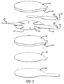
FIG. 5 is an exploded assembly view, in perspective, showing elements of the temperature device ofFIG. 4 . -
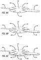
FIGS. 6A-6F illustrate a method of temperature device manufacture based on the temperature device ofFIGS. 4 and5 . - It is desirable that zero heat flux, deep tissue temperature measurement device constructions be disposable. Thus the constructions should be easy and inexpensive to fabricate and assemble, have a low mass and a low profile, and comprise inexpensive materials and parts. It is particularly desirable that disposable DTT measurement device constructions be assembled from low-profile, light weight, flexible assemblies that enable zero heat flux temperature measurement at various locations on a human or animal body.
- A temperature device for zero heat flux deep tissue temperature measurement includes a flexible substrate with at least two thermal sensors disposed in a spaced-apart relationship and separated by one or more flexible layers of thermally insulating material. Preferably the sensors are maintained in a spaced apart relationship by a flexible thermal (and electrical) insulator. The substrate supports at least the thermal sensors, the separating thermal insulator, and a heater.
- Although temperature device constructions are described in terms of preferred embodiments comprising representative elements, the embodiments are merely illustrative. It is possible that other embodiments will include more elements, or fewer, than described. It is also possible that some of the described elements will be deleted, and/or other elements that are not described will be added. Further, elements may be combined with other elements, and/or partitioned into additional elements.
- A layout of an electrical circuit for a temperature measurement device is illustrated in
FIG. 3 . The electrical circuit is disposed on a flexible substrate in order to adapt or conform the physical configuration of the temperature measurement device to differing contours encountered at different temperature measurement locations. Preferably, but not necessarily, the flexible substrate is constructed or fabricated to have a plurality of contiguous sections. For example, theflexible substrate 100 has threecontiguous sections section 102 is substantially circular in shape. The second section (or "tail") 104 has the shape of a narrow, elongate rectangle that extends in a first radial direction from the periphery of thefirst section 102. Where the center section and the tail join at 105, the periphery of the center section has a straight portion and the width of the tail is reduced. The third, or tab,section 106 has the shape of a broad, elongate rectangle that extends in a second radial direction from the periphery of thecenter section 102. Preferably, the tail and tab are aligned along a diameter of the center section. - As per
FIG. 3 , the elements of the electronic circuit are disposed on a single surface, on afirst side 108 of the flexible substrate. A firstthermal sensor 120 is positioned inside the outer perimeter of thecenter section 102, preferably, near or at the center of thecenter section 102. An electricallyconductive heater trace 122 defines a heater with a shape that surrounds or encircles azone 121 in which the firstthermal sensor 120 is located. In the preferred embodiment illustrated inFIG. 3 , the heater trace has an annular shape that includes a circular array of wedge-shapedheater zones 124 that surround or encircle thezone 121 and the firstthermal sensor 120 which is disposed in the zone. A secondthermal sensor 126 is positioned on thetail 104. A plurality ofelectrical connection pads 130 is located in thetab 106. The heater trace includes two electrically conductive trace sections that terminate in theconnection pads thermal sensor 120 is mounted and theconnection pads thermal sensor 126 is mounted and theconnection pads - In the specific layout shown of the preferred embodiment shown in
FIG. 3 , the path of theheater trace 122 crosses the paths of the two traces for the secondthermal sensor 126. In this case, the continuity of the heater trace is preferably, but not necessarily, maintained by an electrically conductive zero-ohm jumper 132 which crosses, and is electrically isolated from, the two traces for the secondthermal sensor 126. In other embodiments, the continuity of theheater trace 122 can also be maintained by vias to the second side of the flexible substrate, by running the thermal sensor traces around the periphery of the first side of the flexible substrate, by a jumper wire instead of the zero-ohm resistor, or by any equivalent solution. - The flexibility or conformability of the flexible substrate can be enhanced by a plurality of
slits 133 that define zones which move or flex independently of each other. In the preferred embodiment, theslits 133 are made in thecenter section 102 in a pattern that follows or accommodates the layout of theheater trace 122. The pattern at least partially separates theheater zones 124 so as to allow any one of theheater zones 124 to move independently of any other heater zone. The preferred pattern of slits is a radial pattern in that each slit is made along a respective radius of thecircular center section 102, between adjacent heater zones, and extends along the radius from the periphery of thecenter section 102 toward the center of the circular shape of the section. This is not meant to exclude other possible slit configurations determined by the different shapes of the heater trace layout and the flexible substrate sections. - Sections of the flexible substrate are brought or folded together about an insulator to provide thermal resistance between the first and second
thermal sensors tail sections thermal sensors FIGS. 3 and4 , thecenter section 102 andtail 104 are folded together about a flexible layer of insulatingmaterial 140. Thelayer 140 provides thermal and electrical resistance between the thermal sensors; it also supports the thermal sensors in a spaced-apart configuration. - A flexible temperature measurement device construction includes an electrical circuit laid out on a side of a flexible substrate as shown in
FIG. 3 . With two sections of the flexible substrate brought or folded together so as to sandwich a flexible insulator, the construction has a multilayer structure as best seen inFIG. 4 . Thus, a temperature measurement device 200 includes the electrical circuit laid out on the surface of thefirst side 108 of theflexible substrate 100. The central andtail sections layer 140 so as to provide a thermal resistance between the first and secondthermal sensors thermal sensor 126 is aligned with the first thermal sensor aline 202 which passes through thezone 121 that is surrounded by the heater trace (seen inFIG. 3 ). The temperature measurement device further includes aflexible heater insulator 208 attached to asecond side 109 of thesubstrate 100, over thecenter section 102. - The layout of the electrical circuit illustrated in
FIG. 3 locates all of the circuit components on a single surface on one side of theflexible substrate 100. This layout confers several advantages. First, it requires only a single fabrication sequence to lay down traces for the heater, the thermal sensors, and the connection pads, thereby simplifying manufacture of the device. Second, when the sections carrying the thermal sensors are folded together, the thermal sensors are maintained within a thermally and mechanically controlled environment. - Another benefit of the preferred layout shown in
FIG. 3 is that the firstthermal sensor 120 is physically removed from the heater, in azone 121 of zero vertical heat flux that is surrounded or encircled by theheater trace 122, and not stacked under it as in the Fox/Solman and Togawa systems. When the temperature measurement device is activated, the heater is turned on and the heat produced thereby travels generally vertically from the heater to the patient, but only medially to the first thermal sensor. As a result, the jump in temperature that occurs when the heater is activated is not immediately sensed by the first thermal sensor, which improves stability of the temperature measurement without requiring an increase in thermal mass of the temperature measurement device. Thus, thefirst temperature sensor 120 is preferably located in the same plane, or on the same surface, as the heater trace 122 (and can even be elevated slightly above the heater trace), and substantially in or in alignment with theregion 121 of zero heat flux. - It is desirable that the temperature measurement device support a pluggable interface for convenience and for modularity of a patient vital signs monitoring system. In this regard, and with reference to
FIGS. 3 and4 , thetab 106 is configured with the array ofpads 130 so as to be able to slide into and out of connection with a plug. In order to provide a physically robust structure capable of maintaining its shape while being connected and disconnected, thetab 106 is optionally stiffened. In this regard, aflexible stiffener 204 is disposed on thesecond side 109 of theflexible substrate 100. The stiffener extends substantially coextensively with thetab 106 and partially over thecenter section 102, at least to the location of the firstthermal sensor 120. As best seen inFIG. 4 , thestiffener 204 is disposed between thesecond side 109 of theflexible substrate 100 and theflexible insulator 208. A key to align thetab 106 with an electrical connector (not shown) and to retain the connector on the tab may be provided on the device 200. For example, with reference toFIG. 5 , such a key includes anopening 209 through the stiffener and tab. In operation, theopening 209 would receive and retain a retractable, spring-loaded pawl on the casing of a plug. - The temperature measurement device 200 is mounted on a region of skin where temperature is to be measured with the second
thermal sensor 126 closest to the skin. As seen inFIG. 4 , a layer ofadhesive 222 is disposed on thesecond side 109, on the layer ofinsulation 140 and the portion of thetail 104 where thesecond sensor 126 is located. A release liner (not shown in this figure) may be peeled from the layer of adhesive 222 to prepare the device 200 for attachment to the skin. When deployed as shown inFIG. 4 , a pluggable signal interface between the electrical circuit on the device 200 and a temperature measurement system is provided through the plurality ofelectrical connection pads 130 located in thetab 106. The signals transferred therethrough would include at least heater activation and thermal sensor signals. - Use of an electrical circuit on a flexible substrate greatly simplifies the construction of a disposable temperature device for estimating deep tissue temperature, and substantially reduces the time and cost of manufacturing such a device. In this regard, manufacture of a temperature measurement device incorporating an electrical circuit laid out on a side of the
flexible substrate 100 with the circuit elements illustrated inFIG. 3 may be understood with reference toFIGS. 5and 6A-6F . Although a manufacturing method is described in terms of specifically numbered steps, it is possible to vary the sequence of the steps while achieving the same result. For various reasons, some of the steps may include more operations, or fewer, than described. For the same or additional reasons, some of the described steps may be deleted, and/or other steps that are not described may be added. Further, steps may be combined with other steps, and/or partitioned into additional steps. - In
FIG. 6A , the traces and pads for an electrical circuit are fabricated on afirst side 108 of aflexible substrate 100 with acenter section 102, atail 104 extending from the center section, and atab 106 extending from the center section. The electronic elements (first and second thermal sensors) are mounted to the traces to complete an electrical circuit (which is omitted from these figures for convenience) including the elements ofFIG. 3 , laid out as shown in that figure. If used, the pattern ofslits 133 separating the heater zones may be made in the center section in this manufacturing step. - As per
FIG. 6B , in a second manufacturing step, astiffener 204 is laminated to a second side of the flexible substrate. As best seen inFIG. 5 , the stiffener has a portion shaped identically to the tab and narrows to an elongated portion with a circular tip. When laminated to thesecond side 109, the stiffener substantially extends over the tab and partially over the center section, beneath thezone 121 where the first thermal sensor is located. Preferably, an adhesive film (not seen) attaches the stiffener to the second side of the flexible substrate, - As per
FIG. 6C , in a third manufacturing step, aflexible layer 208 of insulating material is attached by adhesive or equivalent to the first side of the flexible substrate, over substantially all of the center section and at least a portion of the stiffener. This layer is provided to insulate the heater from the ambient environment. As best seen inFIG. 5 , this flexible layer may include atruncated tab 210 that provides additional reinforcement to a pluggable connection between thetab 106 and a system plug. - As per
FIG. 6D , in a fourth manufacturing step, a flexible central layer of insulatingmaterial 140 is attached to thefirst side 108, over the center section, to cover the heater trace and the first thermal sensor. As best seen inFIG. 5 , this flexible layer may also include atruncated tab 141 that provides additional reinforcement to a pluggable connection between the tab and a system plug. - As per
FIG. 6E , in a fifth manufacturing step, thetail 104 is folded over the central layer of insulatingmaterial 140 such that the first and second thermal sensors are maintained by the central layer in the preferred spaced relationship. - As per
FIG. 6F , in a sixth manufacturing step, a layer of adhesive with arelease liner 226 is attached to the central insulating layer, over the central insulating layer with the tail folded thereto. As best seen inFIG. 5 , therelease liner 226 may have a shape that corresponds to thecentral section 102 andtab 106. - In a best mode of practice, a temperature measurement device according to this specification has been fabricated using the materials and parts listed in the following table. An electrical circuit with copper traces and pads conforming to
FIG. 3 was formed on a flexible substrate of polyimide film by a conventional photo-etching technique and thermal sensors were mounted using a conventional surface mount technique. The dimensions in the table are thicknesses, except that Ǿ signifies diameter. Of course, these materials and dimensions are only illustrative and in no way limit the scope of this specification. For example, traces may be made wholly or partly with electrically conductive ink.Table of Materials and Parts Element Material Representative dimensions Flexible substrate Kapton® film with deposited and photo-etched copper traces and pads Substrate 100: 0.05mm Thermal sensors NTC thermistors, Part # R603-103F-3435-C, Redfish Sensors Flexible insulating layers Closed cell polyethylene foam with skinned major surfaces coated with pressure sensitive adhesive (PSA) Insulator 208: 050 x 1.5mm Insulator 140: 050 x 3.0mm Stiffener Polyethylene terephthalate (PET) Stiffener 204: 0.25mm - The present invention also provides the features as set out in the following paragraphs 1 to 3:
- 1. A temperature device, comprising:
- a flexible substrate; and,
- an electrical circuit on a surface of the flexible substrate, the electrical circuit including an annular heater trace surrounding a zone of the surface, a first thermal sensor disposed in the zone, a second thermal sensor disposed outside of the annular heater trace, a plurality of electrical pads disposed outside of the annular heater trace, and a plurality of conductive traces connecting the first and second thermal sensors and the heater trace with the plurality of electrical pads.
- 2. The temperature device of paragraph 1, in which sections of the flexible substrate are folded together to place the first and second thermal sensors in proximity to one another, between the sections.
- 3. The temperature device of paragraph 2, further including a layer of flexible insulation disposed between the folded-together sections and separating the first and second thermal sensors.
- The present invention further provides the features as set out in the following paragraphs numbered 14-25:
- 14. A temperature device, comprising:
- a flexible substrate having first and second sides;
- the flexible substrate including a circular center section, a tab contiguous with the center section and extending from the center section in a first radial direction, and a tail contiguous with the center section and extending from the center section in a second radial direction;
- a first thermal sensor disposed on the first side, substantially at the center of the center section;
- a heater trace disposed on the first side, in the center section, around the first thermal sensor;
- a second thermal sensor disposed on the first side, in the tail;
- a plurality of electrical pads disposed on the first side, in the tab;
- a plurality of traces disposed on the first side and connecting the first and second thermal sensors and the heater trace with the plurality of electrical pads; the center section and the tail folded together to position the first and second thermal sensors in a spaced apart relationship; and,
- a layer of flexible insulation disposed between the folded-together center section and tail.
- 15. The temperature device of paragraph 14, further comprising a flexible stiffening layer attached to the second side and coextensive with the tab and a portion of the center section.
- 16. The temperature device of paragraph 15, further comprising a layer of flexible insulation coextensive with the center section and attached to the second side and a portion of the stiffening layer.
- 17. The temperature device of paragraph 14, further comprising an electrical connector alignment key on the tab.
- 18. The temperature device of paragraph 14, further comprising a pattern of slits in the center section within which the heater trace is disposed.
- 19. The temperature device of paragraph 18, wherein the pattern of slits and the heater trace define a multi-zone heater.
- 20. The temperature device of paragraph 19, wherein the multi-zone heater includes a plurality of wedge shaped zones.
- 21. The temperature device of paragraph 19, wherein each zone is flexible independently of any other zone.
- 22. The temperature device of paragraph 14, further comprising a reduced width of the tail where the tail joins the center section.
- 23. The temperature device of paragraph 14, further comprising a reduced width of the tail where the center section and tail are folded together.
- 24. A method of temperature device manufacture, comprising:
- fabricating an electrical circuit on a first side of a flexible substrate with a center section, a tab extending from the center section, and a tail extending from the center section, the electrical circuit including a first thermal sensor disposed on the first side, in the center section, a heater trace disposed on the first side, in the center section, around the first thermal sensor, a second thermal sensor disposed on the first side, in the tail, a plurality of electrical pads disposed on the first side, in the tab, and a plurality of traces disposed on the first side and connecting the first and second thermal sensors and the heater trace with the plurality of electrical pads; and then, attaching a flexible heater insulating layer to the second side, over the center section;
- attaching a flexible central insulating layer to the first side, over the center section;
- folding the tail over the central insulating layer; and,
- attaching a layer of adhesive with a release liner to the central insulating layer, over the central insulating layer and the tail.
- 25. The method of
paragraph 24, further comprising:- forming the heater trace in a plurality of heater zones; and
- forming a pattern of slits in the center section, each slit separating one heater zone from an adjacent heater zone.
- 26. The method of paragraph 25, further comprising, attaching a flexible stiffening layer to the second side, coextensively with the tab and a portion of the center section, followed by attaching the flexible heater insulating layer to the second side, over the center section and a portion of the stiffening layer.
Claims (10)
- A temperature device (200), comprising:a flexible substrate (100);a first thermal sensor (120) disposed on a first section (102) of the substrate;a heater trace (122) disposed on the first section with the first thermal sensor;a second thermal sensor (126) disposed on a second section (104) of the substrate;a plurality of electrical pads (130) disposed on a third section (106) of the substrate;a plurality of traces on the flexible substrate connecting the first and second thermal sensors and the heater trace with the plurality of electrical pads;the first and second sections (102,104) disposed in a folded-together configuration in which the first and second thermal sensors are positioned in a spaced apart relationship; and,a flexible insulator (140,208) disposed between the first and second thermal sensors.
- The temperature device of claim 1, wherein the first and second thermal sensors (120,126) and the heater trace (122) are disposed on a first side (108) of the flexible substrate (100), the temperature device further comprising a flexible insulator (140) disposed on a second side (109) of the flexible substrate, over the first section.
- The temperature device of claim 1, further comprising a flexible stiffener (204) disposed on the second side (109) of the flexible substrate, substantially coextensively with the third section.
- The temperature device of claim 3, further comprising an electrical connector alignment key on the third section (106).
- The temperature device of claim 1, further comprising a pattern of slits (133) in the first section (102).
- The temperature device of claim 5, wherein the pattern of slits defines a plurality of heater zones (124) occupied by the heater trace.
- The temperature device of claim 6, wherein the heater zones (124) are wedge-shaped.
- The temperature device of claim 6, wherein each heater zone (124) is flexible independently of any other heater zone.
- The temperature device of claim 8, further comprising a reduced width of the second section (104) where the first and second sections (102,104) are joined.
- The temperature device of claim 1, further comprising a reduced width of the second section (104) where the first and second sections (102,104) are joined.
Priority Applications (1)
| Application Number | Priority Date | Filing Date | Title |
|---|---|---|---|
| EP16199034.6A EP3214419B1 (en) | 2009-08-31 | 2010-08-06 | Flexible deep tissue temperature measurement devices |
Applications Claiming Priority (2)
| Application Number | Priority Date | Filing Date | Title |
|---|---|---|---|
| US12/584,108 US8226294B2 (en) | 2009-08-31 | 2009-08-31 | Flexible deep tissue temperature measurement devices |
| PCT/US2010/002185 WO2011025521A1 (en) | 2009-08-31 | 2010-08-06 | Flexible deep tissue temperature measurement devices |
Related Child Applications (1)
| Application Number | Title | Priority Date | Filing Date |
|---|---|---|---|
| EP16199034.6A Division EP3214419B1 (en) | 2009-08-31 | 2010-08-06 | Flexible deep tissue temperature measurement devices |
Publications (2)
| Publication Number | Publication Date |
|---|---|
| EP2473828A1 EP2473828A1 (en) | 2012-07-11 |
| EP2473828B1 true EP2473828B1 (en) | 2016-11-23 |
Family
ID=43048975
Family Applications (2)
| Application Number | Title | Priority Date | Filing Date |
|---|---|---|---|
| EP10743259.3A Active EP2473828B1 (en) | 2009-08-31 | 2010-08-06 | Flexible deep tissue temperature measurement devices |
| EP16199034.6A Active EP3214419B1 (en) | 2009-08-31 | 2010-08-06 | Flexible deep tissue temperature measurement devices |
Family Applications After (1)
| Application Number | Title | Priority Date | Filing Date |
|---|---|---|---|
| EP16199034.6A Active EP3214419B1 (en) | 2009-08-31 | 2010-08-06 | Flexible deep tissue temperature measurement devices |
Country Status (8)
| Country | Link |
|---|---|
| US (1) | US8226294B2 (en) |
| EP (2) | EP2473828B1 (en) |
| JP (1) | JP5620497B2 (en) |
| CN (1) | CN102498375B (en) |
| AU (1) | AU2010286968B2 (en) |
| BR (1) | BR112012003076A2 (en) |
| IN (1) | IN2012DN01529A (en) |
| WO (1) | WO2011025521A1 (en) |
Families Citing this family (29)
| Publication number | Priority date | Publication date | Assignee | Title |
|---|---|---|---|---|
| JP5181914B2 (en) * | 2008-08-08 | 2013-04-10 | ブラザー工業株式会社 | Positioning method |
| US8939914B2 (en) * | 2009-02-27 | 2015-01-27 | Thermimage, Inc. | Radiometers and related devices and methods |
| US8939913B2 (en) * | 2009-02-27 | 2015-01-27 | Thermimage, Inc. | Monitoring system |
| JP2012524262A (en) | 2009-04-15 | 2012-10-11 | アリザント ヘルスケア インク. | Deep tissue temperature probe structure |
| JP2012524261A (en) * | 2009-04-15 | 2012-10-11 | アリザント ヘルスケア インク. | Deep tissue temperature probe structure |
| WO2011003432A1 (en) * | 2009-07-10 | 2011-01-13 | Stockert Ruediger | Temperature sensor for measurement on or in a living body |
| US8226294B2 (en) * | 2009-08-31 | 2012-07-24 | Arizant Healthcare Inc. | Flexible deep tissue temperature measurement devices |
| US8292495B2 (en) | 2010-04-07 | 2012-10-23 | Arizant Healthcare Inc. | Zero-heat-flux, deep tissue temperature measurement devices with thermal sensor calibration |
| US8292502B2 (en) | 2010-04-07 | 2012-10-23 | Arizant Healthcare Inc. | Constructions for zero-heat-flux, deep tissue temperature measurement devices |
| US9354122B2 (en) | 2011-05-10 | 2016-05-31 | 3M Innovative Properties Company | Zero-heat-flux, deep tissue temperature measurement system |
| GB2497790B (en) * | 2011-12-21 | 2015-01-28 | Olancha Group Ltd | Temperature sensing apparatus and method |
| CA2861622C (en) | 2011-12-23 | 2020-10-27 | Vessix Vascular, Inc. | Methods and apparatuses for remodeling tissue of or adjacent to a body passage |
| US20130331728A1 (en) * | 2012-06-06 | 2013-12-12 | The Charles Stark Draper Laboratory, Inc. | Method and apparatus for determining a core temperature of an internal organ |
| US9220416B2 (en) | 2012-06-22 | 2015-12-29 | Microsoft Technology Licensing, Llc | Heat flux balanced thermometer for measuring human core temperature |
| DE102013000966A1 (en) * | 2013-01-22 | 2014-07-24 | Zimmer Medizinsysteme Gmbh | Method and apparatus for continuous non-invasive measurement of tissue temperatures at different tissue depths |
| JP2016164525A (en) * | 2015-03-06 | 2016-09-08 | セイコーエプソン株式会社 | Temperature measurement device and temperature measurement method |
| US10856741B2 (en) * | 2016-12-14 | 2020-12-08 | Vital Connect, Inc. | Core body temperature detection device |
| FR3060741B1 (en) * | 2016-12-21 | 2018-12-14 | Commissariat A L'energie Atomique Et Aux Energies Alternatives | DEVICE AND METHOD FOR EVALUATING AT LEAST ONE OPERATING CONDITION OF A HEAT EXCHANGER |
| US10820802B2 (en) * | 2016-12-30 | 2020-11-03 | Welch Allyn, Inc. | Wearable patch for patient monitoring |
| WO2018229581A1 (en) | 2017-06-11 | 2018-12-20 | Kenzen Ag | Chip-based multi-channel electrochemical transducer and method of use thereof |
| DE202018104014U1 (en) * | 2018-07-12 | 2018-10-17 | Wema System As | Temperature sensor unit and urea sensor |
| US11872156B2 (en) | 2018-08-22 | 2024-01-16 | Masimo Corporation | Core body temperature measurement |
| CN112996433A (en) * | 2018-10-04 | 2021-06-18 | 奥尼欧有限公司 | Sensor system and method for continuous wireless monitoring and analysis of respiration sound, heart rate and core temperature of a living being |
| WO2020100814A1 (en) * | 2018-11-13 | 2020-05-22 | 株式会社村田製作所 | Adhesion-type clinical thermometer |
| EP3699570A1 (en) * | 2019-02-19 | 2020-08-26 | Nederlandse Organisatie voor toegepast- natuurwetenschappelijk onderzoek TNO | Core body temperature sensor and method for the manufacturing thereof |
| CN110179457B (en) * | 2019-05-31 | 2021-05-07 | 电子科技大学 | Flexible wearable multi-physiological-signal detection device |
| KR102506052B1 (en) * | 2020-11-18 | 2023-03-06 | 재단법인 오송첨단의료산업진흥재단 | Temperature sensor, wearable device having the sensor and method for sensing core temperature using the sensor |
| US20230000667A1 (en) * | 2021-07-01 | 2023-01-05 | Flotherm, Inc. | Flexible heating pads |
| KR20230017981A (en) | 2021-07-29 | 2023-02-07 | 삼성전자주식회사 | Apparatus and method for estimating body temperature |
Family Cites Families (140)
| Publication number | Priority date | Publication date | Assignee | Title |
|---|---|---|---|---|
| US1363259A (en) | 1919-09-19 | 1920-12-28 | Mills David Hirst | Thermometer-cover |
| US1526641A (en) * | 1921-08-09 | 1925-02-17 | Pacific Fire Extinguisher Comp | Thermopile |
| US1638943A (en) * | 1922-09-27 | 1927-08-16 | Westinghouse Electric & Mfg Co | Thermoelectric cell and method of making the same |
| US1528383A (en) * | 1923-06-11 | 1925-03-03 | Schmidt Ernst | Device for the measurement of heat |
| US2378804A (en) * | 1940-05-13 | 1945-06-19 | Honeywell Regulator Co | Thermocouple |
| US2381819A (en) * | 1942-08-19 | 1945-08-07 | Alltools Ltd | Thermocouple |
| US2629757A (en) * | 1943-11-08 | 1953-02-24 | Warren Dunham Foster | Method of construction of sensitive thermopiles |
| US2519785A (en) * | 1944-08-14 | 1950-08-22 | Okolicsanyi Ferenc | Thermopile |
| US2807657A (en) * | 1953-12-21 | 1957-09-24 | North American Aviation Inc | Method of making a thermopile |
| US2969141A (en) * | 1957-06-17 | 1961-01-24 | Eugene M Katzin | Thermometer cover |
| US3099575A (en) * | 1959-10-20 | 1963-07-30 | Engelhard Ind Inc | Thermocouple |
| US3099923A (en) * | 1960-01-18 | 1963-08-06 | Theodor H Benzinger | Thermopile switching systems |
| US3238775A (en) * | 1962-01-02 | 1966-03-08 | Lockheed Aircraft Corp | Heat flux responsive device |
| FI43701B (en) * | 1962-02-14 | 1971-02-01 | H Jaerund | |
| SE303009B (en) | 1962-12-07 | 1968-08-12 | Berger J Welin | |
| US3427209A (en) * | 1965-05-18 | 1969-02-11 | Armstrong Cork Co | Quick response heat-sensing element |
| US3367182A (en) * | 1965-06-02 | 1968-02-06 | Nasa Usa | Heat flux measuring system |
| US3301394A (en) * | 1965-10-15 | 1967-01-31 | Medical Supply Company | Sheath package |
| US3581570A (en) * | 1967-09-05 | 1971-06-01 | Garrett Corp | Thermal radiation sensor |
| US3469685A (en) * | 1967-10-23 | 1969-09-30 | Medical Supply Co | Sheath package and method of application |
| US3767470A (en) | 1968-02-19 | 1973-10-23 | F Hines | Thermally compensated heat flow sensors |
| US3607445A (en) * | 1968-02-19 | 1971-09-21 | Rdf Corp | Thermal apparatus |
| US3552558A (en) * | 1968-06-11 | 1971-01-05 | George W Poncy | Sterile package for clinical thermometers and the like and method of making it |
| GB1354874A (en) * | 1970-05-01 | 1974-06-05 | Nat Res Dev | Temperature measurement |
| US3942123A (en) * | 1970-06-15 | 1976-03-02 | Ivac Corporation | Electronic measurement system |
| US3809230A (en) * | 1970-10-05 | 1974-05-07 | Johnson & Johnson | Sheath-package and method |
| US3720103A (en) * | 1970-11-03 | 1973-03-13 | Cornell Aeronautical Labor Inc | Heat flux measuring system |
| GB1415644A (en) | 1971-11-18 | 1975-11-26 | Johnson Matthey Co Ltd | Resistance thermometer element |
| US3833115A (en) * | 1972-02-24 | 1974-09-03 | R Schapker | Clinical probe and disposable sheath |
| US3877463A (en) * | 1973-07-02 | 1975-04-15 | Massachusetts Inst Technology | Thermal method and device for the differential diagnosis of human tumors and circulatory disorders |
| US4022063A (en) * | 1974-10-15 | 1977-05-10 | Rwb Labs | Electromechanical digital thermometer |
| US4024312A (en) * | 1976-06-23 | 1977-05-17 | Johnson & Johnson | Pressure-sensitive adhesive tape having extensible and elastic backing composed of a block copolymer |
| US4142631A (en) * | 1977-05-09 | 1979-03-06 | Brandriff Robert C | Sterile thermometer sheath |
| DE2835602C2 (en) | 1978-08-14 | 1980-09-04 | Jochen Dr.-Ing. 8035 Gauting Edrich | Method and device for non-contact subcutaneous body temperature distribution determination |
| US4253469A (en) * | 1979-04-20 | 1981-03-03 | The Narda Microwave Corporation | Implantable temperature probe |
| US4275741A (en) * | 1979-08-13 | 1981-06-30 | Jochen Edrich | Procedure for noncontacting measurement of subcutaneous temperature distributions |
| US4347854A (en) * | 1979-10-15 | 1982-09-07 | Gosline Scott P | Bipolar temperature measuring apparatus |
| DE3100610C2 (en) * | 1981-01-12 | 1983-07-07 | Vladimir Dr.-Ing. Blazek | Measuring device for the non-invasive determination of venous or arterial outflow and flow disturbances |
| US4539994A (en) * | 1981-10-13 | 1985-09-10 | Radiometer A/S | Method for transcutaneous measurement of a blood parameter and an electrochemical measuring electrode device for carrying out the method |
| SE442063B (en) * | 1982-04-15 | 1985-11-25 | Minitube Ab | FEVER thermowell |
| US4541734A (en) * | 1982-06-24 | 1985-09-17 | Terumo Kabushiki Kaisha | Electronic clinical thermometer, and method of measuring body temperature |
| JPS58225327A (en) * | 1982-06-24 | 1983-12-27 | Sharp Corp | Electronic clinical thermometer |
| US4592000A (en) * | 1982-06-24 | 1986-05-27 | Terumo Corporation | Electronic clinical thermometer, and method of measuring body temperature |
| DE3346285A1 (en) * | 1982-12-21 | 1984-10-11 | Terumo K.K., Tokio/Tokyo | ELECTRONIC CLINICAL THERMOMETER AND METHOD FOR MEASURING BODY TEMPERATURE |
| US4574359A (en) * | 1982-12-21 | 1986-03-04 | Terumo Kabushiki Kaisha | Electronic clinical thermometer, and method of measuring body temperature |
| JPS60201224A (en) * | 1984-03-27 | 1985-10-11 | Kyushu Daigaku | Multilayered thin-film heat conduction gauge |
| JPS61241631A (en) * | 1985-04-18 | 1986-10-27 | Matsushita Electric Works Ltd | Electronic clinical thermometer |
| DE3527942A1 (en) | 1985-08-03 | 1987-02-12 | Fraunhofer Ges Forschung | Method and device for measuring the core body temperature of biological measurement subjects |
| US4669049A (en) * | 1985-10-08 | 1987-05-26 | Mon-A-Therm, Inc. | Temperature measuring instrument and adapter for same |
| FR2588962B1 (en) * | 1985-10-23 | 1988-01-15 | Centre Nat Rech Scient | SENSOR FOR MEASURING THE THERMAL CONDUCTIVITY OF MATERIALS |
| US4859078A (en) * | 1986-02-07 | 1989-08-22 | Massachusetts Institute Of Technology | Apparatus for the non-invasive measurement of thermal properties and perfusion rates of biomaterials |
| JPH0625700B2 (en) | 1986-03-04 | 1994-04-06 | テルモ株式会社 | Electronic thermometer |
| US4747413A (en) * | 1986-11-07 | 1988-05-31 | Bloch Harry S | Infant temperature measuring apparatus and methods |
| EP0417274B1 (en) * | 1986-11-26 | 1994-01-12 | Terumo Kabushiki Kaisha | Electronic clinical thermometer |
| JPH0795004B2 (en) * | 1986-12-24 | 1995-10-11 | テルモ株式会社 | Body temperature measuring device |
| JPH0638062B2 (en) * | 1987-04-08 | 1994-05-18 | テルモ株式会社 | Automatic inspection device for predictive temperature measuring equipment |
| JPS63253223A (en) * | 1987-04-09 | 1988-10-20 | Terumo Corp | Temperature measuring instrument |
| US5002057A (en) * | 1987-12-28 | 1991-03-26 | G. L. Spaeth | Cover for prism of an applanation tonometer and method of application thereof |
| US5149200A (en) * | 1988-08-25 | 1992-09-22 | Terumo Kabushiki Kaisha | Temperature measuring probe and electronic clinical thermometer equipped with same |
| JP2675344B2 (en) * | 1988-08-25 | 1997-11-12 | テルモ株式会社 | Temperature measuring probe |
| US5178468A (en) * | 1988-08-25 | 1993-01-12 | Terumo Kabushiki Kaisha | Temperature measuring probe and electronic clinical thermometer equipped with same |
| US5199436A (en) * | 1988-12-06 | 1993-04-06 | Exergen Corporation | Radiation detector having improved accuracy |
| US4955380A (en) * | 1988-12-15 | 1990-09-11 | Massachusetts Institute Of Technology | Flexible measurement probes |
| CH678579A5 (en) * | 1989-04-24 | 1991-09-30 | Mettler Toledo Ag | |
| US5050612A (en) * | 1989-09-12 | 1991-09-24 | Matsumura Kenneth N | Device for computer-assisted monitoring of the body |
| US5062432A (en) | 1990-05-09 | 1991-11-05 | Labelle Industries, Inc. | Method and apparatus for monitoring personal core temperature |
| BR9107167A (en) * | 1990-12-12 | 1994-02-22 | Sherwood Ims Inc | BODY TEMPERATURE THERMOMETER AND METHOD OF MEASURING HUMAN BODY TEMPERATURE USING A CALIBRATION MAPPING |
| US5516581A (en) * | 1990-12-20 | 1996-05-14 | Minnesota Mining And Manufacturing Company | Removable adhesive tape |
| US5263775A (en) | 1991-02-01 | 1993-11-23 | Aetrium, Inc. | Apparatus for handling devices under varying temperatures |
| US5172979A (en) | 1991-11-29 | 1992-12-22 | Texaco Inc. | Heater tube skin thermocouple |
| GB2266771B (en) | 1992-04-22 | 1995-11-01 | Robert Lendrum Fyfe | Heatflow balancing thermometer |
| JP3375995B2 (en) * | 1992-11-25 | 2003-02-10 | ミネソタ マイニング アンド マニュファクチャリング カンパニー | Medical temperature sensor |
| US5255979A (en) | 1993-02-01 | 1993-10-26 | Ferrari R Keith | Medical temperature probe cover |
| US6231962B1 (en) * | 1993-08-31 | 2001-05-15 | 3M Innovative Properties Company | Removable foam adhesive tape |
| US5466614A (en) * | 1993-09-20 | 1995-11-14 | At&T Global Information Solutions Company | Structure and method for remotely measuring process data |
| FI96066C (en) | 1994-03-24 | 1996-04-25 | Polar Electro Oy | Method and apparatus for determining the internal temperature and coefficient of heat conduction in a structure |
| US5483190A (en) * | 1994-12-01 | 1996-01-09 | United Technologies Corporation | Floating voltage controlled thermistor/platinum probe emulator |
| US5725308A (en) * | 1994-12-23 | 1998-03-10 | Rtd Technology, Inc. | Quick registering thermometer |
| US6001471A (en) | 1995-08-11 | 1999-12-14 | 3M Innovative Properties Company | Removable adhesive tape with controlled sequential release |
| US5990412A (en) | 1996-05-07 | 1999-11-23 | Vatell Corporation | Differential thermopile heat flux transducer formed by depositing metals and non-metals from liquids onto a substrate |
| US6014890A (en) * | 1996-09-25 | 2000-01-18 | Breen; Peter H. | Fast response humidity and temperature sensor device |
| US5884235A (en) * | 1996-12-17 | 1999-03-16 | Integrated Systems, Inc. | Non-contact, zero-flux temperature sensor |
| IL120758A (en) * | 1997-05-01 | 2000-02-29 | Medisim Ltd | High speed accurate temperature measuring device |
| US6278051B1 (en) * | 1997-10-09 | 2001-08-21 | Vatell Corporation | Differential thermopile heat flux transducer |
| US5993698A (en) | 1997-11-06 | 1999-11-30 | Acheson Industries, Inc. | Electrical device containing positive temperature coefficient resistor composition and method of manufacturing the device |
| US6179159B1 (en) * | 1998-01-26 | 2001-01-30 | Mariruth D. Gurley | Communicable disease barrier digit cover and dispensing package therefor |
| US6224543B1 (en) * | 1998-05-21 | 2001-05-01 | Adroit Medical Systems, Inc. | Non-latex inverted sheath device |
| US6253098B1 (en) * | 1998-09-09 | 2001-06-26 | The United States Of America As Represented By The Secretary Of The Army | Disposable pulse oximeter assembly and protective cover therefor |
| US6292685B1 (en) * | 1998-09-11 | 2001-09-18 | Exergen Corporation | Temporal artery temperature detector |
| US6203191B1 (en) * | 1998-10-28 | 2001-03-20 | Speculative Incorporated | Method of junction temperature determination and control utilizing heat flow |
| US6398727B1 (en) * | 1998-12-23 | 2002-06-04 | Baxter International Inc. | Method and apparatus for providing patient care |
| US6220750B1 (en) * | 1999-03-29 | 2001-04-24 | Yoram Palti | Non-invasive temperature measurement method and apparatus |
| US6355916B1 (en) | 1999-05-18 | 2002-03-12 | Alaris Medical Systems, Inc. | Closed loop system and method for heating a probe |
| US6377848B1 (en) * | 1999-08-25 | 2002-04-23 | Vyteris, Inc. | Devices activating an iontophoretic delivery device |
| US6255622B1 (en) * | 1999-10-27 | 2001-07-03 | Hewlett-Packard Company | Electronic device having external surface thermal feedback |
| US6312391B1 (en) | 2000-02-16 | 2001-11-06 | Urologix, Inc. | Thermodynamic modeling of tissue treatment procedure |
| US20020097775A1 (en) * | 2000-08-29 | 2002-07-25 | Hechmi Hamouda | Heat sensing device for thermal and skin burn evaluation |
| US6773405B2 (en) * | 2000-09-15 | 2004-08-10 | Jacob Fraden | Ear temperature monitor and method of temperature measurement |
| JP3536096B2 (en) | 2000-10-24 | 2004-06-07 | テルモ株式会社 | Deep temperature measuring device |
| GB0103886D0 (en) | 2001-02-16 | 2001-04-04 | Baumbach Per L | Temperature measuring device |
| US6595929B2 (en) * | 2001-03-30 | 2003-07-22 | Bodymedia, Inc. | System for monitoring health, wellness and fitness having a method and apparatus for improved measurement of heat flow |
| EP1249691A1 (en) * | 2001-04-11 | 2002-10-16 | Omron Corporation | Electronic clinical thermometer |
| US6886978B2 (en) * | 2001-06-18 | 2005-05-03 | Omron Corporation | Electronic clinical thermometer |
| DE10139705A1 (en) * | 2001-08-11 | 2003-04-03 | Draeger Medical Ag | Device for measuring body temperature |
| JP4157914B2 (en) * | 2002-03-20 | 2008-10-01 | 坂野 數仁 | Temperature measuring apparatus and temperature measuring method |
| CA2397102C (en) * | 2002-08-07 | 2012-05-29 | Mathis Instruments Ltd. | Direct thermal conductivity measurement technique |
| DE10249853A1 (en) | 2002-10-25 | 2004-05-13 | Liedtke, Rainer K., Dr. | Flexible, plaster-type chip heating system, for thermodynamic control of topical (trans)dermal systems, including supporting matrix, electrical energy source, controlling microprocessor and electric heater |
| US7306283B2 (en) | 2002-11-21 | 2007-12-11 | W.E.T. Automotive Systems Ag | Heater for an automotive vehicle and method of forming same |
| FR2850754B1 (en) * | 2003-02-04 | 2005-04-08 | Seb Sa | NON-INVASIVE ELECTRONIC THERMOMETER |
| US7374336B2 (en) * | 2003-06-16 | 2008-05-20 | Jacob Fraden | Contact thermometer for body cavity |
| FR2858406B1 (en) * | 2003-08-01 | 2005-10-21 | Centre Nat Rech Scient | SENSOR, DEVICE AND METHOD FOR MEASURING INTERFACE PRESSURE BETWEEN TWO BODIES |
| US7270476B2 (en) * | 2003-08-21 | 2007-09-18 | Omron Healthcare Co., Ltd. | Electronic clinical thermometer with quick temperature estimating device |
| DK1734858T3 (en) | 2004-03-22 | 2014-10-20 | Bodymedia Inc | NON-INVASIVE TEMPERATURE MONITORING DEVICE |
| DE102005004933B3 (en) | 2005-02-03 | 2006-08-31 | Dräger Safety AG & Co. KGaA | Device for measuring the body temperature of a living being |
| US7318004B2 (en) * | 2005-04-01 | 2008-01-08 | Cardinal Health 303, Inc. | Temperature prediction system and method |
| DE102005037921B3 (en) * | 2005-08-11 | 2006-06-14 | Dräger Medical AG & Co. KG | Temperature measuring device, for patient use, has evaluating means for detecting skin surface temperature from first temperature measured value and determines temperature at skin surface where double temperature sensor is in contact |
| US8032210B2 (en) * | 2005-10-06 | 2011-10-04 | Spinematrix, Inc. | EMG diagnostic system and method |
| DE102005049676B3 (en) * | 2005-10-18 | 2006-11-16 | Dräger Medical AG & Co. KG | Method of contact-free determination of body temperature of baby involves using surface temperature at particular selected body location |
| US7316507B2 (en) * | 2005-11-03 | 2008-01-08 | Covidien Ag | Electronic thermometer with flex circuit location |
| JP2009517117A (en) | 2005-11-25 | 2009-04-30 | コーニンクレッカ フィリップス エレクトロニクス エヌ ヴィ | Biometric sensor |
| JP2007212407A (en) | 2006-02-13 | 2007-08-23 | Kanazawa Univ | Non-heating type deep part medical thermometer and deep part temperature measuring device using it |
| CA2538940A1 (en) * | 2006-03-03 | 2006-06-22 | James W. Haslett | Bandage with sensors |
| CA2583034C (en) | 2006-03-03 | 2016-01-05 | James W. Haslett | Bandage with sensors |
| US7597668B2 (en) | 2006-05-31 | 2009-10-06 | Medisim Ltd. | Non-invasive temperature measurement |
| US20100121217A1 (en) | 2006-12-06 | 2010-05-13 | Koninklijke Philips Electronics N. V. | Device for measuring core temperature |
| WO2008078271A1 (en) | 2006-12-20 | 2008-07-03 | Philips Intellectual Property & Standards Gmbh | Device and method for measuring core temperature |
| JP5049018B2 (en) * | 2007-01-09 | 2012-10-17 | ソニーモバイルコミュニケーションズ株式会社 | Non-contact charger |
| DE102007002369B3 (en) * | 2007-01-17 | 2008-05-15 | Drägerwerk AG & Co. KGaA | Dual temperature sensor for e.g. patient, has sensor units with connections arranged parallel to each other in block and at distance to each other from external surface of block, where distance is formed by layer of insulating material |
| JP2009080000A (en) | 2007-09-26 | 2009-04-16 | Citizen Holdings Co Ltd | Clinical thermometer |
| BRPI0908620A2 (en) | 2008-05-23 | 2016-06-14 | Koninkl Philips Electronics Nv | sensor assembly adapted to be attached to a body surface of a human or animal or biological species and adapted to measure a core body temperature and method for manufacturing a sensor assembly |
| JP5478874B2 (en) * | 2008-12-02 | 2014-04-23 | 株式会社フィルテック | Substrate, substrate holding device, analysis device, program, detection system, semiconductor device, display device, and semiconductor manufacturing device |
| US8770836B2 (en) * | 2009-01-15 | 2014-07-08 | First Solar, Inc. | Wireless temperature profiling system |
| WO2010082102A2 (en) | 2009-01-19 | 2010-07-22 | Koninklijke Philips Electronics, N.V. | Zero heat flux sensor and method of use |
| CN102348967B (en) | 2009-03-13 | 2014-06-04 | 皇家飞利浦电子股份有限公司 | Zero heat flux temperature sensing device |
| RU2525568C2 (en) | 2009-04-06 | 2014-08-20 | Конинклейке Филипс Электроникс Н.В. | Temperature sensor to measure body temperature |
| JP2012524262A (en) | 2009-04-15 | 2012-10-11 | アリザント ヘルスケア インク. | Deep tissue temperature probe structure |
| JP2012524261A (en) | 2009-04-15 | 2012-10-11 | アリザント ヘルスケア インク. | Deep tissue temperature probe structure |
| US8226294B2 (en) * | 2009-08-31 | 2012-07-24 | Arizant Healthcare Inc. | Flexible deep tissue temperature measurement devices |
| US8292502B2 (en) * | 2010-04-07 | 2012-10-23 | Arizant Healthcare Inc. | Constructions for zero-heat-flux, deep tissue temperature measurement devices |
| US8292495B2 (en) * | 2010-04-07 | 2012-10-23 | Arizant Healthcare Inc. | Zero-heat-flux, deep tissue temperature measurement devices with thermal sensor calibration |
-
2009
- 2009-08-31 US US12/584,108 patent/US8226294B2/en active Active
-
2010
- 2010-08-06 JP JP2012527858A patent/JP5620497B2/en active Active
- 2010-08-06 EP EP10743259.3A patent/EP2473828B1/en active Active
- 2010-08-06 CN CN2010800382237A patent/CN102498375B/en not_active Expired - Fee Related
- 2010-08-06 AU AU2010286968A patent/AU2010286968B2/en not_active Ceased
- 2010-08-06 BR BR112012003076A patent/BR112012003076A2/en not_active IP Right Cessation
- 2010-08-06 WO PCT/US2010/002185 patent/WO2011025521A1/en active Application Filing
- 2010-08-06 EP EP16199034.6A patent/EP3214419B1/en active Active
- 2010-08-06 IN IN1529DEN2012 patent/IN2012DN01529A/en unknown
Also Published As
| Publication number | Publication date |
|---|---|
| JP5620497B2 (en) | 2014-11-05 |
| EP3214419B1 (en) | 2019-01-02 |
| US8226294B2 (en) | 2012-07-24 |
| CN102498375A (en) | 2012-06-13 |
| AU2010286968A1 (en) | 2012-03-01 |
| AU2010286968B2 (en) | 2014-06-19 |
| BR112012003076A2 (en) | 2017-05-02 |
| EP3214419A1 (en) | 2017-09-06 |
| JP2013503355A (en) | 2013-01-31 |
| EP2473828A1 (en) | 2012-07-11 |
| US20110051776A1 (en) | 2011-03-03 |
| IN2012DN01529A (en) | 2015-06-05 |
| WO2011025521A1 (en) | 2011-03-03 |
| CN102498375B (en) | 2013-11-20 |
Similar Documents
| Publication | Publication Date | Title |
|---|---|---|
| EP2473828B1 (en) | Flexible deep tissue temperature measurement devices | |
| EP2556352B1 (en) | Zero-heat-flux, deep tissue temperature measurement device | |
| EP2556351B1 (en) | Zero-heat-flux, deep tissue temperature measurement device with thermal sensor calibration | |
| US20130317388A1 (en) | Zero-heat-flux temperature measurement devices with peripheral skin temperature measurement | |
| EP2419004B1 (en) | Deep tissue temperature probe constructions | |
| US9310257B2 (en) | Deep tissue temperature probe constructions | |
| CN216309249U (en) | Temperature device and zero-heat-flux temperature measurement system | |
| US20210244285A1 (en) | Combined core temperature and skin temperature sensor |
Legal Events
| Date | Code | Title | Description |
|---|---|---|---|
| PUAI | Public reference made under article 153(3) epc to a published international application that has entered the european phase |
Free format text: ORIGINAL CODE: 0009012 |
|
| 17P | Request for examination filed |
Effective date: 20120321 |
|
| AK | Designated contracting states |
Kind code of ref document: A1 Designated state(s): AL AT BE BG CH CY CZ DE DK EE ES FI FR GB GR HR HU IE IS IT LI LT LU LV MC MK MT NL NO PL PT RO SE SI SK SM TR |
|
| DAX | Request for extension of the european patent (deleted) | ||
| RAP1 | Party data changed (applicant data changed or rights of an application transferred) |
Owner name: 3M INNOVATIVE PROPERTIES COMPANY |
|
| GRAP | Despatch of communication of intention to grant a patent |
Free format text: ORIGINAL CODE: EPIDOSNIGR1 |
|
| INTG | Intention to grant announced |
Effective date: 20160603 |
|
| GRAS | Grant fee paid |
Free format text: ORIGINAL CODE: EPIDOSNIGR3 |
|
| GRAA | (expected) grant |
Free format text: ORIGINAL CODE: 0009210 |
|
| AK | Designated contracting states |
Kind code of ref document: B1 Designated state(s): AL AT BE BG CH CY CZ DE DK EE ES FI FR GB GR HR HU IE IS IT LI LT LU LV MC MK MT NL NO PL PT RO SE SI SK SM TR |
|
| REG | Reference to a national code |
Ref country code: GB Ref legal event code: FG4D |
|
| REG | Reference to a national code |
Ref country code: CH Ref legal event code: EP |
|
| REG | Reference to a national code |
Ref country code: IE Ref legal event code: FG4D |
|
| REG | Reference to a national code |
Ref country code: AT Ref legal event code: REF Ref document number: 848342 Country of ref document: AT Kind code of ref document: T Effective date: 20161215 |
|
| REG | Reference to a national code |
Ref country code: DE Ref legal event code: R096 Ref document number: 602010038244 Country of ref document: DE |
|
| PG25 | Lapsed in a contracting state [announced via postgrant information from national office to epo] |
Ref country code: LV Free format text: LAPSE BECAUSE OF FAILURE TO SUBMIT A TRANSLATION OF THE DESCRIPTION OR TO PAY THE FEE WITHIN THE PRESCRIBED TIME-LIMIT Effective date: 20161123 |
|
| REG | Reference to a national code |
Ref country code: LT Ref legal event code: MG4D |
|
| REG | Reference to a national code |
Ref country code: NL Ref legal event code: MP Effective date: 20161123 |
|
| REG | Reference to a national code |
Ref country code: AT Ref legal event code: MK05 Ref document number: 848342 Country of ref document: AT Kind code of ref document: T Effective date: 20161123 |
|
| PG25 | Lapsed in a contracting state [announced via postgrant information from national office to epo] |
Ref country code: LT Free format text: LAPSE BECAUSE OF FAILURE TO SUBMIT A TRANSLATION OF THE DESCRIPTION OR TO PAY THE FEE WITHIN THE PRESCRIBED TIME-LIMIT Effective date: 20161123 Ref country code: GR Free format text: LAPSE BECAUSE OF FAILURE TO SUBMIT A TRANSLATION OF THE DESCRIPTION OR TO PAY THE FEE WITHIN THE PRESCRIBED TIME-LIMIT Effective date: 20170224 Ref country code: NL Free format text: LAPSE BECAUSE OF FAILURE TO SUBMIT A TRANSLATION OF THE DESCRIPTION OR TO PAY THE FEE WITHIN THE PRESCRIBED TIME-LIMIT Effective date: 20161123 Ref country code: SE Free format text: LAPSE BECAUSE OF FAILURE TO SUBMIT A TRANSLATION OF THE DESCRIPTION OR TO PAY THE FEE WITHIN THE PRESCRIBED TIME-LIMIT Effective date: 20161123 Ref country code: NO Free format text: LAPSE BECAUSE OF FAILURE TO SUBMIT A TRANSLATION OF THE DESCRIPTION OR TO PAY THE FEE WITHIN THE PRESCRIBED TIME-LIMIT Effective date: 20170223 |
|
| PG25 | Lapsed in a contracting state [announced via postgrant information from national office to epo] |
Ref country code: HR Free format text: LAPSE BECAUSE OF FAILURE TO SUBMIT A TRANSLATION OF THE DESCRIPTION OR TO PAY THE FEE WITHIN THE PRESCRIBED TIME-LIMIT Effective date: 20161123 Ref country code: PT Free format text: LAPSE BECAUSE OF FAILURE TO SUBMIT A TRANSLATION OF THE DESCRIPTION OR TO PAY THE FEE WITHIN THE PRESCRIBED TIME-LIMIT Effective date: 20170323 Ref country code: FI Free format text: LAPSE BECAUSE OF FAILURE TO SUBMIT A TRANSLATION OF THE DESCRIPTION OR TO PAY THE FEE WITHIN THE PRESCRIBED TIME-LIMIT Effective date: 20161123 Ref country code: ES Free format text: LAPSE BECAUSE OF FAILURE TO SUBMIT A TRANSLATION OF THE DESCRIPTION OR TO PAY THE FEE WITHIN THE PRESCRIBED TIME-LIMIT Effective date: 20161123 Ref country code: AT Free format text: LAPSE BECAUSE OF FAILURE TO SUBMIT A TRANSLATION OF THE DESCRIPTION OR TO PAY THE FEE WITHIN THE PRESCRIBED TIME-LIMIT Effective date: 20161123 Ref country code: PL Free format text: LAPSE BECAUSE OF FAILURE TO SUBMIT A TRANSLATION OF THE DESCRIPTION OR TO PAY THE FEE WITHIN THE PRESCRIBED TIME-LIMIT Effective date: 20161123 |
|
| REG | Reference to a national code |
Ref country code: FR Ref legal event code: PLFP Year of fee payment: 8 |
|
| PG25 | Lapsed in a contracting state [announced via postgrant information from national office to epo] |
Ref country code: RO Free format text: LAPSE BECAUSE OF FAILURE TO SUBMIT A TRANSLATION OF THE DESCRIPTION OR TO PAY THE FEE WITHIN THE PRESCRIBED TIME-LIMIT Effective date: 20161123 Ref country code: SK Free format text: LAPSE BECAUSE OF FAILURE TO SUBMIT A TRANSLATION OF THE DESCRIPTION OR TO PAY THE FEE WITHIN THE PRESCRIBED TIME-LIMIT Effective date: 20161123 Ref country code: CZ Free format text: LAPSE BECAUSE OF FAILURE TO SUBMIT A TRANSLATION OF THE DESCRIPTION OR TO PAY THE FEE WITHIN THE PRESCRIBED TIME-LIMIT Effective date: 20161123 Ref country code: EE Free format text: LAPSE BECAUSE OF FAILURE TO SUBMIT A TRANSLATION OF THE DESCRIPTION OR TO PAY THE FEE WITHIN THE PRESCRIBED TIME-LIMIT Effective date: 20161123 Ref country code: DK Free format text: LAPSE BECAUSE OF FAILURE TO SUBMIT A TRANSLATION OF THE DESCRIPTION OR TO PAY THE FEE WITHIN THE PRESCRIBED TIME-LIMIT Effective date: 20161123 |
|
| REG | Reference to a national code |
Ref country code: DE Ref legal event code: R097 Ref document number: 602010038244 Country of ref document: DE |
|
| PG25 | Lapsed in a contracting state [announced via postgrant information from national office to epo] |
Ref country code: SM Free format text: LAPSE BECAUSE OF FAILURE TO SUBMIT A TRANSLATION OF THE DESCRIPTION OR TO PAY THE FEE WITHIN THE PRESCRIBED TIME-LIMIT Effective date: 20161123 Ref country code: BG Free format text: LAPSE BECAUSE OF FAILURE TO SUBMIT A TRANSLATION OF THE DESCRIPTION OR TO PAY THE FEE WITHIN THE PRESCRIBED TIME-LIMIT Effective date: 20170223 Ref country code: BE Free format text: LAPSE BECAUSE OF FAILURE TO SUBMIT A TRANSLATION OF THE DESCRIPTION OR TO PAY THE FEE WITHIN THE PRESCRIBED TIME-LIMIT Effective date: 20161123 |
|
| PLBE | No opposition filed within time limit |
Free format text: ORIGINAL CODE: 0009261 |
|
| STAA | Information on the status of an ep patent application or granted ep patent |
Free format text: STATUS: NO OPPOSITION FILED WITHIN TIME LIMIT |
|
| PGFP | Annual fee paid to national office [announced via postgrant information from national office to epo] |
Ref country code: IT Payment date: 20170824 Year of fee payment: 8 |
|
| 26N | No opposition filed |
Effective date: 20170824 |
|
| PG25 | Lapsed in a contracting state [announced via postgrant information from national office to epo] |
Ref country code: SI Free format text: LAPSE BECAUSE OF FAILURE TO SUBMIT A TRANSLATION OF THE DESCRIPTION OR TO PAY THE FEE WITHIN THE PRESCRIBED TIME-LIMIT Effective date: 20161123 |
|
| REG | Reference to a national code |
Ref country code: CH Ref legal event code: PL |
|
| PG25 | Lapsed in a contracting state [announced via postgrant information from national office to epo] |
Ref country code: MC Free format text: LAPSE BECAUSE OF FAILURE TO SUBMIT A TRANSLATION OF THE DESCRIPTION OR TO PAY THE FEE WITHIN THE PRESCRIBED TIME-LIMIT Effective date: 20161123 |
|
| PG25 | Lapsed in a contracting state [announced via postgrant information from national office to epo] |
Ref country code: CH Free format text: LAPSE BECAUSE OF NON-PAYMENT OF DUE FEES Effective date: 20170831 Ref country code: LI Free format text: LAPSE BECAUSE OF NON-PAYMENT OF DUE FEES Effective date: 20170831 |
|
| REG | Reference to a national code |
Ref country code: IE Ref legal event code: MM4A |
|
| PG25 | Lapsed in a contracting state [announced via postgrant information from national office to epo] |
Ref country code: LU Free format text: LAPSE BECAUSE OF NON-PAYMENT OF DUE FEES Effective date: 20170806 |
|
| REG | Reference to a national code |
Ref country code: FR Ref legal event code: PLFP Year of fee payment: 9 |
|
| PG25 | Lapsed in a contracting state [announced via postgrant information from national office to epo] |
Ref country code: IE Free format text: LAPSE BECAUSE OF NON-PAYMENT OF DUE FEES Effective date: 20170806 |
|
| PG25 | Lapsed in a contracting state [announced via postgrant information from national office to epo] |
Ref country code: MT Free format text: LAPSE BECAUSE OF NON-PAYMENT OF DUE FEES Effective date: 20170806 |
|
| PG25 | Lapsed in a contracting state [announced via postgrant information from national office to epo] |
Ref country code: HU Free format text: LAPSE BECAUSE OF FAILURE TO SUBMIT A TRANSLATION OF THE DESCRIPTION OR TO PAY THE FEE WITHIN THE PRESCRIBED TIME-LIMIT; INVALID AB INITIO Effective date: 20100806 |
|
| PG25 | Lapsed in a contracting state [announced via postgrant information from national office to epo] |
Ref country code: IT Free format text: LAPSE BECAUSE OF NON-PAYMENT OF DUE FEES Effective date: 20180806 |
|
| PG25 | Lapsed in a contracting state [announced via postgrant information from national office to epo] |
Ref country code: CY Free format text: LAPSE BECAUSE OF NON-PAYMENT OF DUE FEES Effective date: 20161123 |
|
| PG25 | Lapsed in a contracting state [announced via postgrant information from national office to epo] |
Ref country code: MK Free format text: LAPSE BECAUSE OF FAILURE TO SUBMIT A TRANSLATION OF THE DESCRIPTION OR TO PAY THE FEE WITHIN THE PRESCRIBED TIME-LIMIT Effective date: 20161123 |
|
| PG25 | Lapsed in a contracting state [announced via postgrant information from national office to epo] |
Ref country code: TR Free format text: LAPSE BECAUSE OF FAILURE TO SUBMIT A TRANSLATION OF THE DESCRIPTION OR TO PAY THE FEE WITHIN THE PRESCRIBED TIME-LIMIT Effective date: 20161123 |
|
| PG25 | Lapsed in a contracting state [announced via postgrant information from national office to epo] |
Ref country code: AL Free format text: LAPSE BECAUSE OF FAILURE TO SUBMIT A TRANSLATION OF THE DESCRIPTION OR TO PAY THE FEE WITHIN THE PRESCRIBED TIME-LIMIT Effective date: 20161123 Ref country code: IS Free format text: LAPSE BECAUSE OF FAILURE TO SUBMIT A TRANSLATION OF THE DESCRIPTION OR TO PAY THE FEE WITHIN THE PRESCRIBED TIME-LIMIT Effective date: 20170323 |
|
| P01 | Opt-out of the competence of the unified patent court (upc) registered |
Effective date: 20230530 |
|
| PGFP | Annual fee paid to national office [announced via postgrant information from national office to epo] |
Ref country code: GB Payment date: 20230720 Year of fee payment: 14 |
|
| PGFP | Annual fee paid to national office [announced via postgrant information from national office to epo] |
Ref country code: FR Payment date: 20230720 Year of fee payment: 14 Ref country code: DE Payment date: 20230720 Year of fee payment: 14 |
|
| REG | Reference to a national code |
Ref country code: GB Ref legal event code: 732E Free format text: REGISTERED BETWEEN 20240208 AND 20240214 |
|
| REG | Reference to a national code |
Ref country code: DE Ref legal event code: R081 Ref document number: 602010038244 Country of ref document: DE Owner name: SOLVENTUM INTELLECTUAL PROPERTIES CO. (N.D.GES, US Free format text: FORMER OWNER: 3M INNOVATIVE PROPERTIES COMPANY, ST. PAUL, MN, US |