EP2473742B1 - Radialkompressor und verfahren zum herstellen eines radialkompressors - Google Patents
Radialkompressor und verfahren zum herstellen eines radialkompressors Download PDFInfo
- Publication number
- EP2473742B1 EP2473742B1 EP10749770.3A EP10749770A EP2473742B1 EP 2473742 B1 EP2473742 B1 EP 2473742B1 EP 10749770 A EP10749770 A EP 10749770A EP 2473742 B1 EP2473742 B1 EP 2473742B1
- Authority
- EP
- European Patent Office
- Prior art keywords
- compressor
- inlet
- inlet insert
- radial
- fluid
- Prior art date
- Legal status (The legal status is an assumption and is not a legal conclusion. Google has not performed a legal analysis and makes no representation as to the accuracy of the status listed.)
- Not-in-force
Links
Images

Classifications
-
- F—MECHANICAL ENGINEERING; LIGHTING; HEATING; WEAPONS; BLASTING
- F04—POSITIVE - DISPLACEMENT MACHINES FOR LIQUIDS; PUMPS FOR LIQUIDS OR ELASTIC FLUIDS
- F04D—NON-POSITIVE-DISPLACEMENT PUMPS
- F04D29/00—Details, component parts, or accessories
- F04D29/40—Casings; Connections of working fluid
- F04D29/42—Casings; Connections of working fluid for radial or helico-centrifugal pumps
- F04D29/4206—Casings; Connections of working fluid for radial or helico-centrifugal pumps especially adapted for elastic fluid pumps
- F04D29/4213—Casings; Connections of working fluid for radial or helico-centrifugal pumps especially adapted for elastic fluid pumps suction ports
-
- F—MECHANICAL ENGINEERING; LIGHTING; HEATING; WEAPONS; BLASTING
- F04—POSITIVE - DISPLACEMENT MACHINES FOR LIQUIDS; PUMPS FOR LIQUIDS OR ELASTIC FLUIDS
- F04D—NON-POSITIVE-DISPLACEMENT PUMPS
- F04D17/00—Radial-flow pumps, e.g. centrifugal pumps; Helico-centrifugal pumps
- F04D17/08—Centrifugal pumps
- F04D17/10—Centrifugal pumps for compressing or evacuating
-
- F—MECHANICAL ENGINEERING; LIGHTING; HEATING; WEAPONS; BLASTING
- F04—POSITIVE - DISPLACEMENT MACHINES FOR LIQUIDS; PUMPS FOR LIQUIDS OR ELASTIC FLUIDS
- F04D—NON-POSITIVE-DISPLACEMENT PUMPS
- F04D29/00—Details, component parts, or accessories
- F04D29/02—Selection of particular materials
- F04D29/023—Selection of particular materials especially adapted for elastic fluid pumps
-
- F—MECHANICAL ENGINEERING; LIGHTING; HEATING; WEAPONS; BLASTING
- F05—INDEXING SCHEMES RELATING TO ENGINES OR PUMPS IN VARIOUS SUBCLASSES OF CLASSES F01-F04
- F05D—INDEXING SCHEME FOR ASPECTS RELATING TO NON-POSITIVE-DISPLACEMENT MACHINES OR ENGINES, GAS-TURBINES OR JET-PROPULSION PLANTS
- F05D2230/00—Manufacture
- F05D2230/20—Manufacture essentially without removing material
- F05D2230/26—Manufacture essentially without removing material by rolling
-
- F—MECHANICAL ENGINEERING; LIGHTING; HEATING; WEAPONS; BLASTING
- F05—INDEXING SCHEMES RELATING TO ENGINES OR PUMPS IN VARIOUS SUBCLASSES OF CLASSES F01-F04
- F05D—INDEXING SCHEME FOR ASPECTS RELATING TO NON-POSITIVE-DISPLACEMENT MACHINES OR ENGINES, GAS-TURBINES OR JET-PROPULSION PLANTS
- F05D2230/00—Manufacture
- F05D2230/50—Building or constructing in particular ways
- F05D2230/54—Building or constructing in particular ways by sheet metal manufacturing
-
- Y—GENERAL TAGGING OF NEW TECHNOLOGICAL DEVELOPMENTS; GENERAL TAGGING OF CROSS-SECTIONAL TECHNOLOGIES SPANNING OVER SEVERAL SECTIONS OF THE IPC; TECHNICAL SUBJECTS COVERED BY FORMER USPC CROSS-REFERENCE ART COLLECTIONS [XRACs] AND DIGESTS
- Y10—TECHNICAL SUBJECTS COVERED BY FORMER USPC
- Y10T—TECHNICAL SUBJECTS COVERED BY FORMER US CLASSIFICATION
- Y10T29/00—Metal working
- Y10T29/49—Method of mechanical manufacture
- Y10T29/49229—Prime mover or fluid pump making
- Y10T29/49236—Fluid pump or compressor making
- Y10T29/49243—Centrifugal type
Definitions
- the invention relates to a radial compressor and a method for producing a radial compressor.
- Single and multi-stage centrifugal compressors in which one or more compressor impellers are arranged on a compressor shaft in a compressor housing of the respective radial compressor, have for flow guidance the compressor impellers of the respective radial compressor layered in an axial direction of the radial compressor layered or successively arranged stator components, which together form a stator form the radial compressor.
- stator component associated with and optionally surrounding a first impeller stage of a radial compressor is also referred to as an inlet insert and may be e.g. be designed as an inlet heart.
- a compressor housing of the centrifugal compressor via a formed in the compressor housing fluid inlet, which may have an inlet nozzle, and formed in an inlet insert fluid inlet passage, for example, gaseous fluid in a rotating with a compressor shaft compressor impeller and radially out of the compressor impeller in a Diffuser passage, which introduces the fluid into a formed in a Fluidausleitelement fluid outlet passage (a spiral passage or collection passage for discharging accelerated via a last compressor impeller fluid) introduced.
- a Fluidausleitelement fluid outlet passage a spiral passage or collection passage for discharging accelerated via a last compressor impeller fluid
- the fluid is passed to a fluid outlet in the compressor housing, for example provided with a pressure connection, and fed to a subsequent process.
- a collecting space is defined as a passage which is constant across the circumference of the radial compressor.
- the inlet insert disposed in the compressor housing is usually manufactured as a casting, wherein the fluid inlet passage is e.g. produced by casting cores.
- castings have disadvantages in terms of their long delivery times and the models required for the production, which in many cases can not be reused and which significantly increase the manufacturing costs of the castings, and in terms of their possibly fluctuating quality.
- the quality fluctuations in this case relate in particular to the dimensional accuracy (in particular the dimensional accuracy of the fluid inlet passage) and the material structure, which may be impaired in particular by blowholes in castings. Voids may in turn result in cracks and machining problems, or even the need to discard the entire casting.
- radial compressors for manufacturers of such compressors are problematic in terms of compliance with the required operating characteristics, such as reliability and reliability, and compliance with the agreed delivery times.
- the production of such radial compressors for manufacturers can be associated with high cost risks, which can be expressed, for example, in conventional penalties, increased procurement and / or transport costs, etc.
- such conventional radial compressors problematic in terms of standardization and thus cost-effective optimization of the manufacturing process.
- the invention has for its object to provide a radial compressor, which has improved operating characteristics over conventional radial compressors and which can be produced with lower cost risks.
- the invention is further based on the object to provide a method for producing such a radial compressor.
- a centrifugal compressor comprises a compressor housing, a compressor shaft rotatably mounted in the compressor housing, at least one arranged in the compressor housing on the compressor shaft compressor impeller and in a fluid path in the compressor housing a first impeller stage of the radial compressor associated inlet insert certain extension in a radial direction and an axial direction of the radial compressor.
- the inlet insert defines a fluid inlet passage upstream of and in the fluid path of a first compressor impeller of the number of compressor impellers, wherein the inlet insert is formed of material having a defined material structure, and wherein the fluid inlet passage is formed as a subsequently introduced spatial discontinuity in a material cohesion of the material structure.
- Defined material structure in accordance with the invention means that a feedstock feedstock is in a solid state and is expressly not in a melted state, the entirety of any structural irregularities and pattern regularities forming the material structure.
- the fluid inlet passage is produced in particular in its entirety by separating material particles from, in particular, solid-walled or solid starting material, so that a particle number and a volume of the finished inlet insert are smaller than those of the starting material.
- spatial interruption or repeal of the substance cohesion of such a defined material structure of the inlet insert can be exclusively by a separation processing, such as cutting, cutting (eg milling, drilling, turning, grinding, etc.), Abtragen (eg spark erosion, laser cutting , Electron beam cutting, flame cutting, etc.), etc.
- a separation processing such as cutting, cutting (eg milling, drilling, turning, grinding, etc.), Abtragen (eg spark erosion, laser cutting , Electron beam cutting, flame cutting, etc.), etc.
- CNC C omputer N umerically C ontrolled - Computertianischstead
- CNC EDM machines CNC EDM machines
- This can be dispensed with a cost-intensive, lengthy and quality-fluctuating production of the fluid inlet passage by means of casting cores.
- a radial compressor with an inlet insert produced in accordance with the invention thus always has the desired and therefore improved operating properties as a result of the fluid inlet passage which is always of constant quality or dimensional accuracy.
- the material of the inlet insert is pressure-formed material, wherein the material structure of the inlet insert is formed as a pressure-formed material structure.
- pressure-formed material is understood, for example, as forging material, cold-rolling material and hot-rolling material, drawing material, etc. Such materials are available on the market quickly and inexpensively as semi-finished products. Furthermore, pressure-converted materials have a material structure which is improved with respect to air inclusions, since possibly existing air inclusions are forcibly smelted by the pressure forming after a prototyping and thus a more homogeneous material structure is created.
- the material of the inlet insert is rolled material and in particular metal sheet, wherein the material structure of the inlet insert is formed as a rolled material structure.
- metal sheets are available on the market in a variety of sheet thicknesses and material qualities quickly and inexpensively.
- the inlet insert is formed by a plurality of stacked in the axial direction of the radial compressor and interconnected inlet insert parts.
- the inlet insert parts are welded together, soldered or screwed.
- suitable connections may be provided to the compressor housing and adjacent internal parts of the radial compressor.
- the lamination according to the invention or stacking of several inlet insert parts has the advantage that the total extension of the inlet insert in the axial direction of the radial compressor can be distributed to the plurality of thickness dimensions or extensions in the axial direction of the radial compressor of the inlet insert parts.
- the starting material to be used for the respective inlet inserts is at least in one dimension, namely, preferably in the thickness dimension extending in the axial direction of the radial compressor, not limited by the inlet insert as a whole restrictions orrobomindestan beauen. This ensures increased flexibility with regard to the basic dimensions of the starting material for the respective inlet insert parts.
- the problem can easily be solved, for example, that the sheet thickness available on the market is limited.
- the thickness dimension of the inlet insert exceeds, for example, the sheet thickness available on the market, simply several sheets (inlet inserts) are stacked and joined together as described above.
- the geometric shape for the fluid inlet passage can be introduced into each sheet individually or into the sheets in the stratified state.
- the inventive design of the inlet insert from a plurality of inlet insert parts standard inlet insert parts can be defined for certain compressor sizes, so that at least the starting material for these and possibly even finished inlet inserts can be kept in a warehouse.
- radial compressors according to the invention can have a higher degree of standardization, with which a cost optimization of the manufacturing process can be achieved. Furthermore, it is possible to react quickly and flexibly to customer requirements by keeping the stock of certain inlet parts.
- the fluid inlet passage of at least two inlet insert parts of the plurality of inlet insert parts is limited.
- the stacking according to the invention thus makes it possible, if a thickness dimension of the starting material available on the market for the respective inlet insert parts is insufficient to form therein the entire cross section of the fluid inlet passage, distributing the cross section over a plurality of inlet insert parts.
- those skilled in constructing the fluid inlet passage and the inlet insert, respectively are substantially free of constraint-related limitations and thus can realize an optimal design.
- fluid inlet passage can be limited by several inlet insert parts both because of their cross-section and due to a possibly existing axial progression factor.
- a spiral space is formed in an inlet insert part of the plurality of inlet insert parts, wherein the spiral space is formed as a subsequently introduced spatial interruption in the material composition of the material structure.
- a Fluidausleitelement is integrated into the inlet insert in a simple, space-saving and cost-effective manner. This additionally reduces costs and production costs.
- Such an embodiment of the invention is particularly suitable for single-stage centrifugal compressors, but is not limited to these.
- a method of manufacturing a radial compressor comprises at least the following steps: providing a compressor housing, providing a compressor shaft, providing at least one compressor impeller and locating it on the compressor shaft, rotatably supporting the compressor shaft in the compressor housing, providing an inlet insert, such that it has a certain extent in a radial direction and an axial direction of the radial compressor and defines a fluid inlet passage, and arranging the inlet insert in the compressor housing so that the inlet insert in a fluid path in the compressor housing is associated with a first impeller stage of the radial compressor and the fluid inlet passage in the fluid path with a first Compressor impeller of the number of compressor impellers is upstream and leads to this, wherein the fluid inlet passage in particular in their entirety by a Trennbearb in particular from the full in the inlet insert is introduced.
- a severing operation may include, for example, cutting and / or chipping (e.g., milling, drilling, turning, grinding, etc.) and / or ablation (e.g., spark erosion, laser cutting, electron beam cutting, flame cutting, etc.).
- cutting and / or chipping e.g., milling, drilling, turning, grinding, etc.
- ablation e.g., spark erosion, laser cutting, electron beam cutting, flame cutting, etc.
- a radial compressor produced by means of the method according to the invention with an inlet insert designed in accordance with the invention thus always has the desired and therefore improved operating characteristics due to the fluid inlet passage which is always of constant quality or dimensional accuracy.
- pressure-molded material is used as starting material for the inlet insert.
- pressure-formed material for example, forging material, cold rolling and hot rolling, drawing material, etc. understood.
- Such materials are available on the market quickly and inexpensively as semi-finished products.
- pressure-converted materials have a material structure which is improved with respect to air inclusions, since possibly existing air inclusions are forcibly smelted by the pressure forming after a prototyping and thus a more homogeneous material structure is created.
- Rolling material in particular sheet metal, is preferably used as starting material for the inlet insert.
- metal sheets are available on the market in a variety of sheet thicknesses and material qualities quickly and inexpensively.
- solid-walled or solid material is used as starting material for the inlet insert.
- any suitable solid material available on the market can be used, since the fluid inlet passage is only subsequently worked out in its entirety by means of separation processing from the solid.
- the inlet insert when the inlet insert is provided, a plurality of separate inlet insert parts are stacked and connected to one another such that the inlet insert parts are arranged one after the other in the axial direction of the radial compressor, wherein the inlet insert parts are preferably welded, soldered and / or screwed together.
- the lamination according to the invention or stacking of several inlet insert parts has the advantage that the total extension of the inlet insert in the axial direction of the radial compressor can be distributed to the plurality of thickness dimensions or extensions in the axial direction of the radial compressor of the inlet insert parts.
- the starting material to be used for the respective inlet inserts is at least in one dimension, namely, preferably in the thickness dimension extending in the axial direction of the radial compressor, not limited by the inlet insert as a whole restrictions orrobomindestan beauen. This ensures increased flexibility with regard to the basic dimensions of the starting material to be used for the respective inlet insert parts.
- inlet inserts With the stacking of a plurality of inlet inserts according to the invention, it is possible in a simple manner to achieve e.g. solves the problem that the available on the market sheet thickness is limited. In other words, if the thickness dimension of the inlet insert is e.g. exceeds the plate thickness available on the market, simply several sheets (inlet inserts) stacked and connected together as described above.
- the geometric shape for the fluid inlet passage can be introduced into each sheet individually or into the sheets in the stratified state.
- the inventive design of the inlet insert from a plurality of inlet insert parts standard inlet insert parts can be defined for certain compressor sizes, so that at least the starting material for these and possibly even finished inlet inserts can be kept in a warehouse.
- radial compressors according to the invention can have a higher degree of standardization, with which a cost optimization of the manufacturing process can be achieved. Furthermore, it is possible to react quickly and flexibly to customer requirements by keeping the stock of certain inlet parts.
- the fluid inlet passage is introduced such that it is delimited by at least two inlet insert parts of the plurality of inlet insert parts.
- the stacking according to the invention thus makes it possible, if a thickness dimension of the starting material available on the market for the respective inlet insert parts is insufficient to form therein the entire cross section of the fluid inlet passage, distributing the cross section over a plurality of inlet insert parts.
- those skilled in the design and manufacture of the fluid inlet passage or inlet insert are substantially free of constraint-related limitations, and thus can realize optimal design and manufacturing.
- fluid inlet passage can be limited by a plurality of inlet insert parts both due to their cross-section and due to an optionally existing axial progression factor.
- a spiral space is introduced into an inlet insert part of the plurality of inlet insert parts by means of separation processing.
- a Fluidausleitelement is integrated into the inlet insert in a simple, space-saving and cost-effective manner. This additionally reduces costs and production costs.
- Such an embodiment of the invention is particularly suitable for single-stage centrifugal compressors, but is not limited to these.
- a cutting and / or abrading machining is used as the cutting process.
- processing methods carried out by a CNC machine such as e.g. Milling, spark erosion, laser cutting, electron beam cutting and flame cutting. This allows the geometry of the fluid inlet passage in repeatable quality and high dimensional accuracy reliably produced.
- these can be bolted together, soldered or welded. If the sheets are screwed together, the screw can also be part of the screwing of the entire stator.
- the invention not only allows the use of sheets, but also allows the construction of a standard component system.
- the radial compressor is a single-shaft centrifugal compressor.
- FIGS. 1 to 3 a radial compressor 1 according to embodiments of the invention described.
- a radial compressor 1 has a compressor housing 10, a compressor shaft 20 mounted rotatably in the compressor housing 10, at least one compressor impeller 14 arranged in the compressor housing 10 and an inlet insert 12 assigned to a first impeller stage of the radial compressor 1 in a fluid path in the compressor housing 10 which has a certain extent in a radial direction RR and an axial direction AR (see FIG Fig.1 and Figure 3 ) of the radial compressor 1 has.
- gaseous and / or liquid fluid is introduced into the compressor impeller 14 rotating with the compressor shaft 20 via a fluid inlet 11 formed in the compressor housing 10, which may have an inlet port (not shown) and a fluid inlet passage 13 formed in the inlet insert 12 and radially out of the compressor impeller 14 into a diffuser passage 15 which introduces the fluid into a fluid discharge passage 16a (a spiral passage or collection passage) formed in a fluid discharge member 16.
- a fluid discharge passage 16a a spiral passage or collection passage
- the fluid is passed to a fluid outlet 17 provided in the compressor housing 10, for example with a pressure connection (not shown), and supplied to a subsequent process.
- the fluid inlet passage 13 in the inlet insert 12 in the fluid path is the first (and according to the in Fig.1 embodiment shown single) compressor impeller 14 upstream and leads or extends to this point.
- the fluid inlet passage 13 is bounded by all three of the inlet insert parts 12a, 12b, 12c, at least by means of a wall section thereof.
- inlet insert part 12c is formed a fluid outlet passage in the form of a spiral space 121c.
- the spiral space 121c forms a modification to that in FIG Fig.1
- the fluid outlet passage, wherein the inlet insert part 12c forms the Fluidausleitelement is particularly suitable for a single-stage radial compressor.
- the spiral space 121c in the inlet insert part 12c may also be omitted, and instead the fluid outlet passage as in FIG Fig.1 can be arranged shown.
- the left inlet insert part 12a is designed as a conical disk
- the inlet insert part 12b in these figures is designed as an inlet heart
- the inlet insert part 12c which is the right in these figures is formed as a fluid discharge element or spiral casing element.
- the inlet insert 12 is made of a material having a defined material structure, namely according to embodiments of the invention of pressure-formed material and in particular of rolled sheet metal.
- the material structure of the inlet insert 12 and the respective inlet insert parts 12a, 12b, 12c, a pressure-formed material structure and here in particular a rolling material structure are regarded as a defined material structure, namely according to embodiments of the invention of pressure-formed material and in particular of rolled sheet metal.
- the fluid inlet passage 13 and the spiral space 121c are introduced into the solid wall starting material (sheet metal) of the inlet insert 12 and the respective inlet insert parts 12a, 12b, 12c by a cutting process.
- the fluid inlet passage 13 and the spiral space 121c each represent a subsequently introduced spatial interruption in a material cohesion of the material structure of the inlet insert 12.
- a method of manufacturing the radial compressor 1 thus comprises the steps of providing the compressor housing 10, providing the compressor shaft 20, providing at least one compressor impeller 14, and placing it on the compressor shaft 20 rotatably supporting the compressor shaft 20 in the compressor housing 10 Providing the inlet insert 12 so that it has a certain extent in the radial direction RR and in the axial direction AR of the radial compressor 1 and defining a fluid inlet passage 13, and arranging the inlet insert 12 in the compressor housing 10 so that the inlet insert 12 in the fluid path in the compressor housing 10 of a first Impeller is associated with the radial compressor 1 and the fluid inlet passage 13 upstream of the first compressor impeller 14 in the fluid path and leads to this, wherein the fluid inlet passage 13 is introduced by a separation processing in the inlet insert 12.
- the inlet insert 12 as in the Figures 2 and 3 shown from a plurality of stacked in the axial direction AR of the radial compressor 1 Intake insert parts 12a, 12b, 12c are produced, wherein the inlet insert parts 12a, 12b, 12c are welded together, soldered or screwed.
- the fluid inlet passage 13 may be inserted so that they, as in the Figures 2 and 3 shown, is bounded by all three inlet inserts 12a, 12b, 12c.
- the geometric shape for the fluid inlet passage 13 may be introduced into each inlet insert part 12a, 12b, 12c individually or into the inlet insert parts 12a, 12b, 12c in the stratified state. Also, the spiral space 121c, if provided, may be introduced into the most downstream inlet insert part 12c before or after the joining or stacking of the inlet insert parts 12a, 12b, 12c by cutting treatment.
- the fluid inlet passage 13 and, optionally, the spiral space 121c may be e.g. be machined by milling and / or spark erosion from the full starting material or introduced into this.
- the starting material for the inlet insert 12 or the respective inlet insert parts 12a, 12b, 12c can be pressure-formed material and preferably rolled material, in particular sheet metal.
Landscapes
- Engineering & Computer Science (AREA)
- Mechanical Engineering (AREA)
- General Engineering & Computer Science (AREA)
- Structures Of Non-Positive Displacement Pumps (AREA)
Description
- Die Erfindung betrifft einen Radialkompressor und ein Verfahren zum Herstellen eines Radialkompressors.
- Ein- und mehrstufige Radialkompressoren, bei denen ein oder mehrere Kompressorlaufräder auf einer Kompressorwelle in einem Kompressorgehäuse des jeweiligen Radialkompressors angeordnet sind, weisen zur Strömungsführung die Kompressorlaufräder des jeweiligen Radialkompressors umgebende in einer Axialrichtung des Radialkompressors geschichtete bzw. hintereinander angeordnete Statorbauteile auf, die zusammen ein Statorpaket des Radialkompressors bilden.
- Das einer ersten Laufradstufe eines Radialkompressors zugeordnete und diese ggf. umgebende Statorbauteil wird auch als Einlaufeinsatz bezeichnet und kann z.B. als Einlaufherz ausgebildet sein.
- Gemäß dem Stand der Technik wird in einem Kompressorgehäuse des Radialkompressors über einen im Kompressorgehäuse ausgebildeten Fluideinlass, welcher einen Einlassstutzen aufweisen kann, und eine in einem Einlaufeinsatz ausgebildete Fluideinlasspassage z.B. gasförmiges Fluid in ein mit einer Kompressorwelle rotierendes Kompressorlaufrad eingeleitet und aus dem Kompressorlaufrad heraus radial in eine Diffusorpassage hineingefördert, die das Fluid in eine in einem Fluidausleitelement ausgebildete Fluidauslasspassage (eine Spiralpassage oder Sammelpassage zum Ausleiten von über ein letztes Kompressorlaufrad beschleunigtem Fluid) einleitet. Über die Fluidauslasspassage wird das Fluid zu einem z.B. mit einem Druckstutzen versehenen Fluidauslass im Kompressorgehäuse geleitet und einem nachfolgenden Prozess zugeführt.
- Als Spiralpassage wird eine sich über den Umfang des Radialkompressors entwickelnde bzw. querschnittsmäßig vergrößernde Passage bezeichnet. Als Sammelraum wird dahingegen eine über den Umfang des Radialkompressors querschnittskonstante Passage bezeichnet.
- Der im Kompressorgehäuse angeordnete Einlaufeinsatz wird üblicherweise als Gussteil hergestellt, wobei die Fluideinlasspassage z.B. durch Gusskerne hergestellt wird. Gussteile weisen jedoch Nachteile hinsichtlich ihrer langen Lieferzeiten und der zur Herstellung erforderlichen Modelle, die in vielen Fällen nicht wiederverwendet werden können und die die Herstellungskosten für die Gussteile erheblich vergrößernd beeinflussen, und hinsichtlich ihrer ggf. schwankenden Qualität auf.
- Die Qualitätsschwankungen betreffen hierbei insbesondere die Maßhaltigkeit (hier insbesondere die Maßhaltigkeit der Fluideinlasspassage) und die Materialstruktur, welche bei Gussteilen insbesondere von Lunkern beeinträchtigt sein kann. Lunker können wiederum zu Rissen und zu Bearbeitungsproblemen oder sogar zu der Notwendigkeit des Verwerfens des gesamten Gussteils führen.
- Im Ergebnis sind mit solch üblichen Einlaufeinsätzen ausgerüstete Radialkompressoren für Hersteller solcher Kompressoren problematisch hinsichtlich der Einhaltung der geforderten Betriebseigenschaften, wie der Betriebssicherheit bzw. Ausfallsicherheit, und der Einhaltung der vereinbarten Lieferzeiten. Damit kann die Herstellung solcher Radialkompressoren für Hersteller mit hohen Kostenrisiken verbunden sein, welche sich z.B. in Konventionalstrafen, erhöhten Beschaffungs- und/oder Transportkosten usw. ausdrücken können. Ferner sind solche üblichen Radialkompressoren problematisch hinsichtlich einer Standardisierung und damit kostenmäßigen Optimierung des Herstellungsprozesses.
- Die aus dem Stand der Technik bekannte Druckschrift
US 2009/0060727 A1 beschäftigt sich mit der Anordnung von Einlaufeinsätzen in einem Kompressorgehäuse, wobei der Einlaufeinsatz grundsätzlich mehrteilig ist und nur eins der Teile den eigentlichen Einlauf bildet und die übrigen Teile die Befestigung im Gehäuse gewährleisten. Die funktionsgebundenen Mehrteiligkeit erfordert in der Regel auf den Einzelfall abgestimmte Bauteile, was nachteilig in Bezug auf die Kombination von verschieden dimensionierten Einlaufeinsätzen ist. - Die Dokumente
US 4,212,585 undDE 10 2007 042 529 A1 zeigen ebenfalls Einlaufeinsätze in Kompressorgehäusen, diese sind in Bezug auf die vorgegebene geometrische Ausgestaltung des Kompressorgehäuses sowie des Kompressorlaufrades speziell geformt, was auch hier nachteilig in Bezug auf die Kombination von verschiedenen Einlaufeinsätzen ist. - Der Erfindung liegt die Aufgabe zugrunde, einen Radialkompressor bereitzustellen, welcher gegenüber üblichen Radialkompressoren verbesserte Betriebseigenschaften aufweist und welcher mit geringeren Kostenrisiken herstellbar ist. Der Erfindung liegt ferner die Aufgabe zugrunde, ein Verfahren zum Herstellen eines solchen Radialkompressors bereitzustellen.
- Die o.g. Aufgaben werden mit einem Radialkompressor gemäß Anspruch 1 bzw. einem Verfahren gemäß Anspruch 8 gelöst. Weiterbildungen der Erfindung sind in den jeweils abhängigen Ansprüchen definiert.
- Gemäß einem ersten Aspekt der Erfindung weist ein Radialkompressor ein Kompressorgehäuse, eine drehbar in dem Kompressorgehäuse gelagerte Kompressorwelle, wenigstens ein in dem Kompressorgehäuse auf der Kompressorwelle angeordnetes Kompressorlaufrad und einen in einem Fluidpfad im Kompressorgehäuse einer ersten Laufradstufe des Radialkompressors zugeordneten Einlaufeinsatz bestimmter Erstreckung in einer Radialrichtung und einer Axialrichtung des Radialkompressors auf. Erfindungsgemäß definiert der Einlaufeinsatz eine im Fluidpfad einem ersten Kompressorlaufrad der Anzahl von Kompressorlaufrädern vorgeordnete und zu diesem hin führende Fluideinlasspassage, wobei der Einlaufeinsatz von Material mit einer definierten Materialstruktur gebildet ist und wobei die Fluideinlasspassage als nachträglich eingebrachte räumliche Unterbrechung in einem Stoffzusammenhalt der Materialstruktur ausgebildet ist.
- Definierte Materialstruktur bedeutet gemäß der Erfindung, dass ein Ausgangsmaterial für den Einlaufeinsatz sich in einem Festkörperzustand und ausdrücklich nicht in einem Schmelzzustand befindet, wobei die Gesamtheit jeglicher Strukturunregelmäßigkeiten und Strukturregelmäßigkeiten die Materialstruktur bilden. Mit anderen Worten ist die Fluideinlasspassage insbesondere in ihrer Gesamtheit durch Abtrennen von Werkstoffteilchen vom insbesondere vollwandigen bzw. massiven Ausgangsmaterial hergestellt, so dass eine Teilchenzahl und ein Volumen des fertigen Einlaufeinsatzes geringer als jene des Ausgangsmaterials sind.
- Eine wie gemäß der Erfindung vorgesehene räumliche Unterbrechung bzw. Aufhebung des Stoffzusammenhalts einer solchen definierten Materialstruktur des Einlaufeinsatzes lässt sich ausschließlich durch eine Trennbearbeitung, wie beispielsweise Zerteilen, Spanen (z.B. Fräsen, Bohren, Drehen, Schleifen usw.), Abtragen (z.B. Funkenerodieren, Laserschneiden, Elektronenstrahlschneiden, Brennschneiden usw.) usw., erzielen.
- Mit einem Trennverfahren lassen sich jedoch mit den heute verfügbaren z.B. CNC (Computer Numerically Controlled - Computernummerischgesteuert) -Maschinen, wie z.B. CNC-Fräsmaschinen, CNC-Funkenerodiermaschinen usw., erheblich höhere Genauigkeiten, insbesondere auch für die Fluideinlasspassage, erzielen. Damit kann auf eine kostenintensive, langwierige und qualitätsschwankende Herstellung der Fluideinlasspassage mittels Gusskernen verzichtet werden.
- Ein Radialkompressor mit einem erfindungsgemäß hergestellten Einlaufeinsatz weist somit durch die mit stets gleichbleibender Qualität bzw. Maßhaltigkeit hergestellte Fluideinlasspassage stets die gewünschten und damit verbesserte Betriebseigenschaften auf. Durch die z.B. damit reduzierten Risiken hinsichtlich lieferzeitbedingter und/oder qualitätsbedingter Konventionalstrafen und/oder höherer Beschaffungskosten und/oder höherer Transportkosten für den Hersteller eines solchen Radialkompressors sind insgesamt die Kostenrisiken bei der Herstellung des Radialkompressors reduziert.
- Gemäß einer Ausführungsform des erfindungsgemäßen Radialkompressors ist das Material des Einlaufeinsatzes druckumgeformtes Material, wobei die Materialstruktur des Einlaufeinsatzes als Druckumgeformt-Materialstruktur ausgebildet ist.
- Erfindungsgemäß wird unter druckumgeformtem Material beispielsweise Schmiedematerial, Kaltwalzmaterial und Warmwalzmaterial, Ziehmaterial usw. verstanden. Solche Materialien sind am Markt schnell und preiswert als Halbzeuge verfügbar. Ferner weisen druckumgeformte Materialien eine hinsichtlich Lufteinschlüssen verbesserte Materialstruktur auf, da durch die Druckumformung nach einem Urformen ggf. vorhandene Lufteinschlüsse gewissermaßen verschmiedet werden und damit eine homogenere Materialstruktur geschaffen wird.
- Bevorzugt ist das Material des Einlaufeinsatzes Walzmaterial und insbesondere Metallblech, wobei die Materialstruktur des Einlaufeinsatzes als Walzmaterialstruktur ausgebildet ist. Insbesondere Metallbleche sind am Markt in einer Vielzahl von Blechdicken und Materialqualitäten schnell und preiswert verfügbar.
- Gemäß einer Ausführungsform des erfindungsgemäßen Radialkompressors ist der Einlaufeinsatz von einer Mehrzahl von in Axialrichtung des Radialkompressors aufeinandergeschichteten und miteinander verbundenen Einlaufeinsatzteilen gebildet. Bevorzugt sind die Einlaufeinsatzteile miteinander verschweißt, verlötet oder verschraubt. Zusätzlich können geeignete Verbindungen zum Kompressorgehäuse und benachbarten Innenteilen des Radialkompressors vorgesehen sein.
- Die erfindungsgemäße Laminierung bzw. Aufeinanderschichtung mehrerer Einlaufeinsatzteile hat den Vorteil, dass die Gesamterstreckung des Einlaufeinsatzes in Axialrichtung des Radialkompressors auf die mehreren Dickenabmessungen bzw. Erstreckungen in Axialrichtung des Radialkompressors der Einlaufeinsatzteile verteilbar ist. Damit unterliegt das für die jeweiligen Einlaufeinsatzteile zu verwendende Ausgangsmaterial zumindest in einer Dimension, nämlich hier bevorzugt in der sich in Axialrichtung des Radialkompressors erstreckenden Dickendimension, nicht den durch den Einlaufeinsatz als Ganzes vorgegebenen Beschränkungen bzw. Größenmindestanforderungen. Damit wird eine erhöhte Flexibilität hinsichtlich der Grundabmessungen des Ausgangsmaterials für die jeweiligen Einlaufeinsatzteile sichergestellt.
- Mit der erfindungsgemäßen Aufeinanderschichtung mehrerer Einlaufeinsatzteile, kann auf einfache Weise z.B. das Problem gelöst werden, dass die am Markt verfügbare Blechdicke beschränkt ist. Mit anderen Worten werden, wenn die Dickenabmessung des Einlaufeinsatzes z.B. die am Markt verfügbare Blechdicke überschreitet, einfach mehrere Bleche (Einlaufeinsatzteile) aufeinandergeschichtet und wie oben beschrieben miteinander verbunden. Die geometrische Form für die Fluideinlasspassage kann in jedes Blech einzeln oder in die Bleche im Geschichtet-Zustand eingebracht werden.
- Durch die erfindungsgemäße Ausbildung des Einlaufeinsatzes aus mehreren Einlaufeinsatzteilen können für bestimmte Kompressorbaugrößen Standard-Einlaufeinsatzteile definiert werden, so dass zumindest das Ausgangsmaterial für diese und ggf. sogar fertige Einlaufeinsatzteile in einem Lager vorgehalten werden können. Damit können erfindungsgemäße Radialkompressoren einen höheren Standardisierungsgrad aufweisen, womit eine kostenmäßige Optimierung des Herstellungsprozesses erzielbar ist. Ferner ist es durch eine Lagervorhaltung von bestimmten Einlaufeinsatzteilen möglich, schnell und flexibel auf Kundenwünsche zu reagieren.
- Gemäß einer Ausführungsform des erfindungsgemäßen Radialkompressors ist die Fluideinlasspassage von wenigstens zwei Einlaufeinsatzteilen der Mehrzahl von Einlaufeinsatzteilen begrenzt.
- Durch die erfindungsgemäße Aufeinanderschichtung ist es somit möglich, wenn eine auf dem Markt verfügbare Dickendimension des Ausgangsmaterials für die jeweiligen Einlaufeinsatzteile nicht ausreicht, um darin den gesamten Querschnitt der Fluideinlasspassage auszubilden, den Querschnitt auf mehrere Einlaufeinsatzteile zu verteilen. Damit unterliegt der Fachmann beim Konstruieren der Fluideinlasspassage bzw. des Einlaufeinsatzes im Wesentlichen keinen ausgangsmaterialbedingten Beschränkungen und kann somit eine optimale Konstruktion realisieren.
- In diesem Zusammenhang ist zu bemerken, dass die Fluideinlasspassage sowohl aufgrund ihres Querschnitts als auch aufgrund eines ggf. vorhandenen axialen Verlaufsfaktors von mehreren Einlaufeinsatzteilen begrenzt sein kann.
- Gemäß einer Ausführungsform des erfindungsgemäßen Radialkompressors ist in einem Einlaufeinsatzteil der Mehrzahl von Einlaufeinsatzteilen ein Spiralraum ausgebildet, wobei der Spiralraum als nachträglich eingebrachte räumliche Unterbrechung im Stoffzusammenhalt der Materialstruktur ausgebildet ist.
- Gemäß dieser Ausgestaltung der Erfindung ist auf einfache, raumsparende und kostengünstige Weise ein Fluidausleitelement in den Einlaufeinsatz integriert. Dies reduziert zusätzlich die Kosten und den Fertigungsaufwand. Besonders geeignet ist eine solche Ausgestaltung der Erfindung für einstufige Radialkompressoren, ist aber nicht auf diese beschränkt.
- Gemäß einem zweiten Aspekt der Erfindung weist ein Verfahren zum Herstellen eines Radialkompressors zumindest die folgenden Schritte auf: Bereitstellen eines Kompressorgehäuses, Bereitstellen einer Kompressorwelle, Bereitstellen wenigstens eines Kompressorlaufrades und Anordnen dessen auf der Kompressorwelle, drehbares Lagern der Kompressorwelle in dem Kompressorgehäuse, Bereitstellen eines Einlaufeinsatzes, so dass dieser eine bestimmte Erstreckung in einer Radialrichtung und einer Axialrichtung des Radialkompressors aufweist und eine Fluideinlasspassage definiert, und Anordnen des Einlaufeinsatzes im Kompressorgehäuse, so dass der Einlaufeinsatz in einem Fluidpfad im Kompressorgehäuse einer ersten Laufradstufe des Radialkompressors zugeordnet ist und die Fluideinlasspassage im Fluidpfad einem ersten Kompressorlaufrad der Anzahl von Kompressorlaufrädern vorgeordnet ist und zu diesem hin führt, wobei die Fluideinlasspassage insbesondere in ihrer Gesamtheit durch eine Trennbearbeitung insbesondere aus dem Vollen in den Einlaufeinsatz eingebracht wird.
- Gemäß der Erfindung kann eine Trennbearbeitung beispielsweise ein Zerteilen und/oder ein Spanen (z.B. Fräsen, Bohren, Drehen, Schleifen usw.) und/oder ein Abtragen (z.B. Funkenerodieren, Laserschneiden, Elektronenstrahlschneiden, Brennschneiden usw.) beinhalten.
- Mit einem erfindungsgemäßen Trennverfahren lassen sich mit den heute verfügbaren z.B. CNC-Maschinen, wie z.B. CNC-Fräsmaschinen, CNC-Funkenerodiermaschinen usw., erheblich höhere Genauigkeiten, insbesondere auch für die Fluideinlasspassage, erzielen. Damit kann auf eine kostenintensive, langwierige und qualitätsschwankende Herstellung der Fluideinlasspassage mittels Gusskernen verzichtet werden.
- Ein mittels des erfindungsgemäßen Verfahrens hergestellter Radialkompressor mit einem erfindungsgemäß ausgebildeten Einlaufeinsatz weist somit durch die mit stets gleichbleibender Qualität bzw. Maßhaltigkeit hergestellte Fluideinlasspassage stets die gewünschten und damit verbesserte Betriebseigenschaften auf. Durch die z.B. damit reduzierten Risiken hinsichtlich lieferzeitbedingter und/oder qualitätsbedingter Konventionalstrafen und/oder höherer Beschaffungskosten und/oder höherer Transportkosten für den Hersteller eines solchen Radialkompressors sind insgesamt die Kostenrisiken bei der Herstellung des Radialkompressors reduziert.
- Gemäß einer Ausführungsform des erfindungsgemäßen Verfahrens wird als Ausgangsmaterial für den Einlaufeinsatz druckumgeformtes Material verwendet.
- Wie oben bereits erwähnt, wird gemäß der Erfindung unter druckumgeformtem Material beispielsweise Schmiedematerial, Kaltwalzmaterial und Warmwalzmaterial, Ziehmaterial usw. verstanden. Solche Materialien sind am Markt schnell und preiswert als Halbzeuge verfügbar. Ferner weisen druckumgeformte Materialien eine hinsichtlich Lufteinschlüssen verbesserte Materialstruktur auf, da durch die Druckumformung nach einem Urformen ggf. vorhandene Lufteinschlüsse gewissermaßen verschmiedet werden und damit eine homogenere Materialstruktur geschaffen wird.
- Bevorzugt wird als Ausgangsmaterial für den Einlaufeinsatz Walzmaterial, insbesondere Metallblech, verwendet. Insbesondere Metallbleche sind am Markt in einer Vielzahl von Blechdicken und Materialqualitäten schnell und preiswert verfügbar.
- Gemäß einer Ausführungsform des erfindungsgemäßen Verfahrens wird als Ausgangsmaterial für den Einlaufeinsatz vollwandiges bzw. massives Material verwendet.
- Mit anderen Worten kann als Ausgangsmaterial jegliches am Markt verfügbare geeignete Vollmaterial verwendet werden, da die Fluideinlasspassage erst nachträglich in ihrer Gesamtheit per Trennbearbeitung aus dem Vollen herausgearbeitet wird.
- Gemäß einer Ausführungsform des erfindungsgemäßen Verfahrens werden beim Bereitstellen des Einlaufeinsatzes eine Mehrzahl von separaten Einlaufeinsatzteilen so aufeinandergeschichtet und miteinander verbunden, dass die Einlaufeinsatzteile in Axialrichtung des Radialkompressors nacheinander angeordnet sind, wobei die Einlaufeinsatzteile bevorzugt miteinander verschweißt, verlötet und/oder verschraubt werden.
- Die erfindungsgemäße Laminierung bzw. Aufeinanderschichtung mehrerer Einlaufeinsatzteile hat den Vorteil, dass die Gesamterstreckung des Einlaufeinsatzes in Axialrichtung des Radialkompressors auf die mehreren Dickenabmessungen bzw. Erstreckungen in Axialrichtung des Radialkompressors der Einlaufeinsatzteile verteilbar ist. Damit unterliegt das für die jeweiligen Einlaufeinsatzteile zu verwendende Ausgangsmaterial zumindest in einer Dimension, nämlich hier bevorzugt in der sich in Axialrichtung des Radialkompressors erstreckenden Dickendimension, nicht den durch den Einlaufeinsatz als Ganzes vorgegebenen Beschränkungen bzw. Größenmindestanforderungen. Damit wird eine erhöhte Flexibilität hinsichtlich der Grundabmessungen des zu verwendenden Ausgangsmaterials für die jeweiligen Einlaufeinsatzteile sichergestellt.
- Mit der erfindungsgemäßen Aufeinanderschichtung mehrerer Einlaufeinsatzteile, kann auf einfache Weise z.B. das Problem gelöst werden, dass die am Markt verfügbare Blechdicke beschränkt ist. Mit anderen Worten werden, wenn die Dickenabmessung des Einlaufeinsatzes z.B. die am Markt verfügbare Blechdicke überschreitet, einfach mehrere Bleche (Einlaufeinsatzteile) aufeinandergeschichtet und wie oben beschrieben miteinander verbunden. Die geometrische Form für die Fluideinlasspassage kann in jedes Blech einzeln oder in die Bleche im Geschichtet-Zustand eingebracht werden.
- Durch die erfindungsgemäße Ausbildung des Einlaufeinsatzes aus mehreren Einlaufeinsatzteilen können für bestimmte Kompressorbaugrößen Standard-Einlaufeinsatzteile definiert werden, so dass zumindest das Ausgangsmaterial für diese und ggf. sogar fertige Einlaufeinsatzteile in einem Lager vorgehalten werden können. Damit können erfindungsgemäße Radialkompressoren einen höheren Standardisierungsgrad aufweisen, womit eine kostenmäßige Optimierung des Herstellungsprozesses erzielbar ist. Ferner ist es durch eine Lagervorhaltung von bestimmten Einlaufeinsatzteilen möglich, schnell und flexibel auf Kundenwünsche zu reagieren.
- Gemäß einer Ausführungsform des erfindungsgemäßen Verfahrens wird die Fluideinlasspassage so eingebracht, dass sie von wenigstens zwei Einlaufeinsatzteilen der Mehrzahl von Einlaufeinsatzteilen begrenzt wird.
- Durch die erfindungsgemäße Aufeinanderschichtung ist es somit möglich, wenn eine auf dem Markt verfügbare Dickendimension des Ausgangsmaterials für die jeweiligen Einlaufeinsatzteile nicht ausreicht, um darin den gesamten Querschnitt der Fluideinlasspassage auszubilden, den Querschnitt auf mehrere Einlaufeinsatzteile zu verteilen. Damit unterliegt der Fachmann beim Konstruieren und Herstellen der Fluideinlasspassage bzw. des Einlaufeinsatzes im Wesentlichen keinen ausgangsmaterialbedingten Beschränkungen und kann somit eine optimale Konstruktion und Fertigung realisieren.
- In diesem Zusammenhang ist zu bemerken, dass die Fluideinlasspassage sowohl aufgrund ihres Querschnitts als auch aufgrund eines ggf. vorhandenen axialen Verlaufsfaktors von mehreren Einlaufeinsatzteilen begrenzt werden kann.
- Gemäß einer Ausführungsform des erfindungsgemäßen Verfahrens wird in ein Einlaufeinsatzteil der Mehrzahl von Einlaufeinsatzteilen per Trennbearbeitung ein Spiralraum eingebracht.
- Gemäß dieser Ausgestaltung der Erfindung wird auf einfache, raumsparende und kostengünstige Weise ein Fluidausleitelement in den Einlaufeinsatz integriert. Dies reduziert zusätzlich die Kosten und den Fertigungsaufwand. Besonders geeignet ist eine solche Ausgestaltung der Erfindung für einstufige Radialkompressoren, ist aber nicht auf diese beschränkt.
- Gemäß einer Ausführungsform des erfindungsgemäßen Verfahrens wird als Trennbearbeitung eine spanende und/oder eine abtragende Bearbeitung eingesetzt.
- Gerade für räumlich verlaufende Geometrien wie die Fluideinlasspassage eignen sich per CNC-Maschine durchgeführte Bearbeitungsverfahren wie z.B. Fräsen, Funkenerodieren, Laserschneiden, Elektronenstrahlschneiden und Brennschneiden. Damit lässt sich die Geometrie der Fluideinlasspassage in wiederholbarer Qualität und hoher Maßgenauigkeit zuverlässig herstellen.
- Im Fazit wird gemäß Ausführungsformen beider Aspekte der Erfindung vorgeschlagen, die Gussteile für Einlaufeinsätze durch jeweils aus mindestens einem Blech bzw. Blechen überwiegend spanend hergestellte Bauteile zu ersetzen. Bei geeigneter Formgebung der strömungsführenden Fluideinlasspassage kann diese aus einem oder bei nicht ausreichend zur Verfügung stehender Blechdicke mehreren geschichteten Blechen spanabhebend und/oder durch erosive und/oder durch schneidende Verfahren (Laser, Elektronenstrahl, Brennschneiden) hergestellt werden.
- Bei geschichteten Blechen können diese miteinander verschraubt, verlötet oder verschweißt werden. Werden die Bleche miteinander verschraubt, kann die Verschraubung auch Bestandteil der Verschraubung des gesamten Statorpaketes sein.
- Die Erfindung erlaubt nicht nur den Einsatz von Blechen, sondern ermöglicht auch den Aufbau einer Standard-Bauteilsystematik.
- Erfindungsgemäß besteht keine Beschränkung auf einstufige Radialkompressoren, sondern die Erfindung ist z.B. auch für mehrstufige Radialkompressoren sowohl in Barrelbauweise als auch in horizontal geteilter Bauweise anwendbar.
- Gemäß einer Ausführungsform der Erfindung ist der Radialkompressor ein einwelliger Radialkompressor.
- Im Folgenden wird die Erfindung anhand bevorzugter Ausführungsformen und unter Bezugnahme auf die beigefügten Figuren beschrieben.
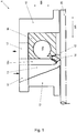
- Fig.1
- zeigt eine schematische Schnittansicht eines Radialkompressors gemäß einer Ausführungsform der Erfindung.
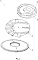
- Fig.2
- zeigt eine perspektivische Explosionsansicht eines Einlaufeinsatzes eines Radialkompressors gemäß einer Ausführungsform der Erfindung.
- Fig.3
- zeigt eine seitliche Explosionsansicht des Einlaufeinsatzes von
Fig.2 . - Im Folgenden wird unter Bezugnahme auf die
Figuren 1 bis 3 ein Radialkompressor 1 gemäß Ausführungsformen der Erfindung beschrieben. - Ein erfindungsgemäßer Radialkompressor 1 weist ein Kompressorgehäuse 10, eine drehbar in dem Kompressorgehäuse 10 gelagerte Kompressorwelle 20, wenigstens ein in dem Kompressorgehäuse 10 auf der Kompressorwelle 20 angeordnetes Kompressorlaufrad 14 und ein in einem Fluidpfad im Kompressorgehäuse 10 einer ersten Laufradstufe des Radialkompressors 1 zugeordneten Einlaufeinsatz 12 auf, welcher eine bestimmte Erstreckung in einer Radialrichtung RR und einer Axialrichtung AR (siehe
Fig.1 undFig.3 ) des Radialkompressors 1 hat. - Im Betrieb des erfindungsgemäßen Radialkompressors 1 wird über einen im Kompressorgehäuse 10 ausgebildeten Fluideinlass 11, welcher einen Einlassstutzen (nicht gezeigt) aufweisen kann, und eine im Einlaufeinsatz 12 ausgebildete Fluideinlasspassage 13 gasförmiges und/oder flüssiges Fluid in das mit der Kompressorwelle 20 rotierende Kompressorlaufrad 14 eingeleitet und aus dem Kompressorlaufrad 14 heraus radial in eine Diffusorpassage 15 hineingefördert, die das Fluid in eine in einem Fluidausleitelement 16 ausgebildete Fluidauslasspassage 16a (eine Spiralpassage oder Sammelpassage) einleitet.
- Über die Fluidauslasspassage 16a wird das Fluid zu einem z.B. mit einem Druckstutzen (nicht gezeigt) versehenen Fluidauslass 17 im Kompressorgehäuse 10 geleitet und einem nachfolgenden Prozess zugeführt.
- Wie aus
Fig.1 ersichtlich, ist die Fluideinlasspassage 13 im Einlaufeinsatz 12 im Fluidpfad dem ersten (und gemäß der inFig.1 gezeigten Ausführungsform einzigen) Kompressorlaufrad 14 vorgeordnet und führt bzw. erstreckt sich zu diesem hin. - Wie aus
Fig.2 undFig.3 ersichtlich, ist der Einlaufeinsatz 12 von drei in Axialrichtung AR des Radialkompressors 1 aufeinandergeschichteten und miteinander verbundenen Einlaufeinsatzteilen 12a, 12b, 12c gebildet, wobei die Einlaufeinsatzteile gemäß Ausführungsformen der Erfindung miteinander verschweißt, verlötet und/oder verschraubt (nicht im Detail dargestellt) sind. - Wie ebenfalls aus
Fig.2 undFig.3 ersichtlich, ist die Fluideinlasspassage 13 von allen dreien der Einlaufeinsatzteile 12a, 12b, 12c zumindest mittels eines Wandabschnitts dieser begrenzt. - In dem in
Fig.2 undFig.3 rechten Einlaufeinsatzteil 12c ist eine Fluidauslasspassage in Form eines Spiralraums 121c ausgebildet. Der Spiralraum 121c bildet als Modifikation zu der inFig.1 gezeigten Ausführungsform die Fluidauslasspassage, wobei das Einlaufeinsatzteil 12c das Fluidausleitelement bildet. Eine solche Konfiguration ist insbesondere für einen einstufigen Radialkompressor geeignet. Es ist zu bemerken, dass gemäß Ausführungsformen der Erfindung der Spiralraum 121c im Einlaufeinsatzteil 12c auch weggelassen sein kann und stattdessen die Fluidauslasspassage wie inFig.1 gezeigt angeordnet sein kann. - Gemäß der in
Fig.2 undFig.3 gezeigten Ausführungsform der Erfindung ist das in diesen Figuren linke Einlaufeinsatzteil 12a als Kegelscheibe ausgebildet, ist das in diesen Figuren mittlere Einlaufeinsatzteil 12b als Einlaufherz ausgebildet und ist das in diesen Figuren rechte Einlaufeinsatzteil 12c als Fluidausleitelement bzw. Spiralgehäuseelement ausgebildet. - Der Einlaufeinsatz 12 ist aus einem Material mit einer definierten Materialstruktur hergestellt, nämlich gemäß Ausführungsformen der Erfindung aus druckumgeformtem Material und hier insbesondere aus gewalztem Metallblech. Mit anderen Worten ist die Materialstruktur des Einlaufeinsatzes 12 bzw. der jeweiligen Einlaufeinsatzteile 12a, 12b, 12c eine Druckumgeformt-Materialstruktur und hier insbesondere eine Walzmaterialstruktur.
- Gemäß der Erfindung sind die Fluideinlasspassage 13 und der Spiralraum 121c durch eine Trennbearbeitung in das vollwandige Ausgangsmaterial (Metallblech) des Einlaufeinsatzes 12 bzw. der jeweiligen Einlaufeinsatzteile 12a, 12b, 12c eingebracht.
- Damit stellen die Fluideinlasspassage 13 und der Spiralraum 121c jeweils eine nachträglich eingebrachte räumliche Unterbrechung in einem Stoffzusammenhalt der Materialstruktur des Einlaufeinsatzes 12 dar.
- In einer einfachsten Form weist ein Verfahren zum Herstellen des Radialkompressors 1 demnach die folgenden Schritte auf: Bereitstellen des Kompressorgehäuses 10, Bereitstellen der Kompressorwelle 20, Bereitstellen wenigstens eines Kompressorlaufrades 14 und Anordnen dessen auf der Kompressorwelle 20, drehbares Lagern der Kompressorwelle 20 in dem Kompressorgehäuse 10, Bereitstellen des Einlaufeinsatzes 12, so dass dieser eine bestimmte Erstreckung in Radialrichtung RR und in Axialrichtung AR des Radialkompressors 1 aufweist und eine Fluideinlasspassage 13 definiert, und Anordnen des Einlaufeinsatzes 12 im Kompressorgehäuse 10, so dass der Einlaufeinsatz 12 im Fluidpfad im Kompressorgehäuse 10 einer ersten Laufradstufe des Radialkompressors 1 zugeordnet ist und die Fluideinlasspassage 13 im Fluidpfad dem ersten Kompressorlaufrad 14 vorgeordnet ist und zu diesem hin führt, wobei die Fluideinlasspassage 13 durch eine Trennbearbeitung in den Einlaufeinsatz 12 eingebracht wird.
- Gemäß Ausführungsformen des erfindungsgemäßen Verfahrens kann der Einlaufeinsatz 12, wie in den
Figuren 2 und3 gezeigt, aus einer Mehrzahl von in Axialrichtung AR des Radialkompressors 1 aufeinandergeschichteten Einlaufeinsatzteilen 12a, 12b, 12c hergestellt werden, wobei die Einlaufeinsatzteile 12a, 12b, 12c miteinander verschweißt, verlötet oder verschraubt werden. - Die Fluideinlasspassage 13 kann so eingebracht werden, dass sie, wie in den
Figuren 2 und3 gezeigt, von allen drei Einlaufeinsatzteilen 12a, 12b, 12c begrenzt wird. - Die geometrische Form für die Fluideinlasspassage 13 kann in jedes Einlaufeinsatzteil 12a, 12b, 12c einzeln oder in die Einlaufeinsatzteile 12a, 12b, 12c im Geschichtet-Zustand eingebracht werden. Auch der Spiralraum 121c kann, wenn vorgesehen, vor oder nach dem miteinander Verbinden bzw. Aufeinanderschichten der Einlaufeinsatzteile 12a, 12b, 12c per Trennbearbeitung in das strömungsabwärtigste Einlaufeinsatzteil 12c eingebracht werden.
- Als Trennbearbeitung werden bevorzugt eine spanende und/oder eine abtragende Bearbeitung eingesetzt. Demnach können gemäß Ausführungsformen der Erfindung die Fluideinlasspassage 13 und ggf. der Spiralraum 121c z.B. per Fräsen und/oder Funkenerodieren aus dem vollen Ausgangsmaterial herausgearbeitet bzw. in dieses eingebracht werden.
- Als Ausgangsmaterial für den Einlaufeinsatz 12 bzw. die jeweiligen Einlaufeinsatzteile 12a, 12b, 12c kann druckumgeformtes Material und bevorzugt Walzmaterial, insbesondere Metallblech, verwendet werden.
-
- 1
- Radialkompressor
- 10
- Kompressorgehäuse
- 11
- Fluideinlass
- 12
- Einlaufeinsatz
- 12a
- Einlaufeinsatzteil
- 12b
- Einlaufeinsatzteil
- 12c
- Einlaufeinsatzteil
- 121c
- Spiralraum
- 13
- Fluideinlasspassage
- 14
- Kompressorlaufrad
- 15
- Diffusorpassage
- 16
- Fluidausleitelement
- 16a
- Fluidausleitpassage
- 17
- Fluidauslass
- 20
- Kompressorwelle
- AR
- Axialrichtung
- RR
- Radialrichtung
Claims (12)
- Radialkompressor (1) mit einem Kompressorgehäuse (10), einer drehbar in dem Kompressorgehäuse (10) gelagerten Kompressorwelle (20), wenigstens einem in dem Kompressorgehäuse (10) auf der Kompressorwelle (20) angeordneten Kompressorlaufrad (14) und einem in einem Fluidpfad im Kompressorgehäuse (10) einer ersten Laufradstufe des Radialkompressors (1) zugeordneten Einlaufeinsatz (12) bestimmter Erstreckung in einer Radialrichtung (RR) und einer Axialrichtung (AR) des Radialkompressors (1),
wobei der Einlaufeinsatz (12) eine im Fluidpfad einem ersten Kompressorlaufrad (14) vorgeordnete und zu diesem hin führende Fluideinlasspassage (13) definiert,
wobei der Einlaufeinsatz (12) von Material mit einer definierten Materialstruktur gebildet ist, und
wobei die Fluideinlasspassage (13) als nachträglich eingebrachte räumliche Unterbrechung in einem Stoffzusammenhalt der Materialstruktur ausgebildet ist, wobei der Einlaufeinsatz (12) von einer Mehrzahl von in Axialrichtung (AR) des Radialkompressors (1) aufeinandergeschichteten und miteinander verbundenen Einlaufeinsatzteilen (12a, 12b, 12c) gebildet ist,
dadurch gekennzeichnet,
dass in einem Einlaufeinsatzteil (12c) der Mehrzahl von Einlaufeinsatzteilen (12a, 12b, 12c) ein Spiralraum (121c) ausgebildet ist, und wobei der Spiralraum (121c) als nachträglich eingebrachte räumliche Unterbrechung im Stoffzusammenhalt der Materialstruktur ausgebildet ist. - Radialkompressor (1) gemäß Anspruch 1, wobei das Material des Einlaufeinsatzes (12) druckumgeformtes Material ist, und wobei die Materialstruktur des Einlaufeinsatzes (12) als Druckumgeformt-Materialstruktur ausgebildet ist.
- Radialkompressor (1) gemäß Anspruch 1 oder 2, wobei das Material des Einlaufeinsatzes (12) Walzmaterial und insbesondere Metallblech ist, und wobei die Materialstruktur des Einlaufeinsatzes (12) als Walzmaterialstruktur ausgebildet ist.
- Radialkompressor (1) gemäß Anspruch 1 wobei die Einlaufeinsatzteile (12a, 12b, 12c) miteinander verschweißt, verlötet oder verschraubt sind.
- Radialkompressor (1) gemäß Anspruch 1 oder 4, wobei die Fluideinlasspassage (13) von wenigstens zwei Einlaufeinsatzteilen (12a, 12b, 12c) der Mehrzahl von Einlaufeinsatzteilen (12a, 12b, 12c) begrenzt ist.
- Verfahren zum Herstellen eines Radialkompressors (1), aufweisend:Bereitstellen eines Kompressorgehäuses (10),Bereitstellen einer Kompressorwelle (20),Bereitstellen wenigstens eines Kompressorlaufrades (14) und Anordnen dessen auf der Kompressorwelle (20),drehbares Lagern der Kompressorwelle (20) in dem Kompressorgehäuse (10),Bereitstellen eines Einlaufeinsatzes (12), so dass dieser eine bestimmte Erstreckung in einer Radialrichtung (RR) und in einer Axialrichtung (AR) des Radialkompressors (1) aufweist und eine Fluideinlasspassage (13) definiert, undAnordnen des Einlaufeinsatzes (12) im Kompressorgehäuse (10), so dass der Einlaufeinsatz (12) in einem Fluidpfad im Kompressorgehäuse (10) einer ersten Laufradstufe des Radialkompressors (1) zugeordnet ist und die Fluideinlasspassage (13) im Fluidpfad einem ersten Kompressorlaufrad (14) vorgeordnet ist und zu diesem hin führt,wobei die Fluideinlasspassage (13) durch eine Trennbearbeitung in den Einlaufeinsatz (12) eingebracht wird, wobei beim Bereitstellen des Einlaufeinsatzes (12) eine Mehrzahl von separaten Einlaufeinsatzteilen (12a, 12b, 12c) so aufeinandergeschichtet und miteinander verbunden werden, dass die Einlaufeinsatzteile (12a, 12b, 12c) in Axialrichtung (AR) des Radialkompressors (1) nacheinander angeordnet sind.dadurch gekennzeichnet.
dass in ein Einlaufeinsatzteil (12c) der Mehrzahl von Einlaufeinsatzteilen (12a, 12b, 12c) per Trennbearbeitung ein Spiralraum (121c) eingebracht wird. - Verfahren gemäß Anspruch 6, wobei als Ausgangsmaterial für den Einlaufeinsatz (12) druckumgeformtes Material verwendet wird.
- Verfahren gemäß Anspruch 6 oder 7, wobei als Ausgangsmaterial für den Einlaufeinsatz (12) Walzmaterial, insbesondere Metallblech, verwendet wird.
- Verfahren gemäß einem der Ansprüche 6 bis 8, wobei als Ausgangsmaterial für den Einlaufeinsatz (12) vollwandiges Material verwendet wird.
- Verfahren gemäß Anspruch 6, wobei die Einlaufeinsatzteile (12a, 12b, 12c) miteinander verschweißt, verlötet oder verschraubt werden.
- Verfahren gemäß Anspruch 6 oder 10, wobei die Fluideinlasspassage (13) so eingebracht wird, dass sie von wenigstens zwei Einlaufeinsatzteilen (12a, 12b, 12c) der Mehrzahl von Einlaufeinsatzteilen (12a, 12b, 12c) begrenzt wird.
- Verfahren gemäß einem der Ansprüche 6 bis 11, wobei als Trennbearbeitung eine spanende und/oder eine abtragende Bearbeitung eingesetzt wird.
Applications Claiming Priority (2)
| Application Number | Priority Date | Filing Date | Title |
|---|---|---|---|
| DE102009035575A DE102009035575A1 (de) | 2009-07-31 | 2009-07-31 | Radialkompressor und Verfahren zum Herstellen eines Radialkompressors |
| PCT/DE2010/050049 WO2011012127A1 (de) | 2009-07-31 | 2010-07-21 | Radialkompressor und verfahren zum herstellen eines radialkompressors |
Publications (2)
| Publication Number | Publication Date |
|---|---|
| EP2473742A1 EP2473742A1 (de) | 2012-07-11 |
| EP2473742B1 true EP2473742B1 (de) | 2017-12-27 |
Family
ID=43063846
Family Applications (1)
| Application Number | Title | Priority Date | Filing Date |
|---|---|---|---|
| EP10749770.3A Not-in-force EP2473742B1 (de) | 2009-07-31 | 2010-07-21 | Radialkompressor und verfahren zum herstellen eines radialkompressors |
Country Status (8)
| Country | Link |
|---|---|
| US (1) | US9488189B2 (de) |
| EP (1) | EP2473742B1 (de) |
| JP (1) | JP5893557B2 (de) |
| CN (1) | CN102575686B (de) |
| DE (1) | DE102009035575A1 (de) |
| RU (1) | RU2484309C1 (de) |
| UA (1) | UA105230C2 (de) |
| WO (1) | WO2011012127A1 (de) |
Families Citing this family (1)
| Publication number | Priority date | Publication date | Assignee | Title |
|---|---|---|---|---|
| DE102017208783A1 (de) * | 2017-05-24 | 2018-11-29 | Robert Bosch Gmbh | Verfahren zum Nachbearbeiten eines Kanals in einem Werkstück |
Family Cites Families (20)
| Publication number | Priority date | Publication date | Assignee | Title |
|---|---|---|---|---|
| US3103892A (en) * | 1960-11-21 | 1963-09-17 | Laval Turbine | Pump or the like |
| US3733145A (en) * | 1971-03-04 | 1973-05-15 | Nevsky Mash | Vand-type centrifugal machine, mainly, high-pressure compressor |
| US4007996A (en) * | 1976-01-22 | 1977-02-15 | Boone Henry S | Turbine engine and pump |
| SU591616A1 (ru) * | 1976-06-04 | 1978-02-05 | Предприятие П/Я А-1665 | Центробежный компрессор |
| US4137006A (en) | 1977-01-26 | 1979-01-30 | K B Southern, Inc. | Composite horizontally split casing |
| US4212585A (en) * | 1978-01-20 | 1980-07-15 | Northern Research And Engineering Corporation | Centrifugal compressor |
| DE3232326C2 (de) * | 1982-08-31 | 1985-10-03 | Klein, Schanzlin & Becker Ag, 6710 Frankenthal | Topfgehäuse für Kreiselpumpen |
| US4676717A (en) * | 1985-05-22 | 1987-06-30 | Cummins Atlantic, Inc. | Compressor housing having replaceable inlet throat and method for manufacturing compressor housing |
| JPH01108301U (de) * | 1988-01-13 | 1989-07-21 | ||
| DE8912547U1 (de) | 1988-12-27 | 1990-02-01 | Oregon Etablissement für Patentverwertung, Mauren | Schutzhelm, insbesondere Polizeihelm |
| US5076758A (en) * | 1990-07-18 | 1991-12-31 | Ingersoll-Rand Company | Centrifugal pumps |
| RU2112154C1 (ru) * | 1996-08-21 | 1998-05-27 | Григорий Григорьевич Петросян | Регулируемый диффузор центробежного компрессора |
| US20040109760A1 (en) * | 2002-12-04 | 2004-06-10 | Jones Daniel W. | Method and apparatus for increasing the adiabatic efficiency of a centrifugal compressor |
| JP3838200B2 (ja) | 2003-01-09 | 2006-10-25 | 株式会社デンソー | 遠心式送風装置 |
| EP1719879B1 (de) * | 2005-05-03 | 2008-01-30 | ABB Turbo Systems AG | Berstschutzvorrichtung für Radialverdichter |
| EP1910687B1 (de) * | 2005-08-02 | 2019-01-02 | Honeywell International Inc. | Verdichtergehäuse mit variabler geometrie und verfahren zu dessen herstellung |
| DE102007019884A1 (de) * | 2007-04-27 | 2008-11-06 | Bayerische Motoren Werke Aktiengesellschaft | Verdichter für einen Abgasturbolader |
| US8857053B2 (en) * | 2007-08-29 | 2014-10-14 | Caterpillar Inc. | Compressor housing remanufacturing method and apparatus |
| DE102007042529A1 (de) * | 2007-09-07 | 2009-03-12 | Man Turbo Ag | Strömungsmaschine und Herstellungsverfahren für eine solche Strömungsmaschine |
| DE102008025249A1 (de) * | 2008-05-27 | 2009-12-03 | Siemens Aktiengesellschaft | Sammelraum und Verfahren zur Fertigung |
-
2009
- 2009-07-31 DE DE102009035575A patent/DE102009035575A1/de not_active Withdrawn
-
2010
- 2010-07-21 CN CN201080034190.9A patent/CN102575686B/zh not_active Expired - Fee Related
- 2010-07-21 EP EP10749770.3A patent/EP2473742B1/de not_active Not-in-force
- 2010-07-21 UA UAA201202344A patent/UA105230C2/ru unknown
- 2010-07-21 US US13/387,879 patent/US9488189B2/en not_active Expired - Fee Related
- 2010-07-21 JP JP2012521965A patent/JP5893557B2/ja not_active Expired - Fee Related
- 2010-07-21 WO PCT/DE2010/050049 patent/WO2011012127A1/de not_active Ceased
- 2010-07-21 RU RU2012107389/06A patent/RU2484309C1/ru active
Also Published As
| Publication number | Publication date |
|---|---|
| WO2011012127A1 (de) | 2011-02-03 |
| US20120156023A1 (en) | 2012-06-21 |
| EP2473742A1 (de) | 2012-07-11 |
| US9488189B2 (en) | 2016-11-08 |
| JP2013501177A (ja) | 2013-01-10 |
| CN102575686A (zh) | 2012-07-11 |
| UA105230C2 (ru) | 2014-04-25 |
| DE102009035575A1 (de) | 2011-03-03 |
| CN102575686B (zh) | 2014-12-24 |
| JP5893557B2 (ja) | 2016-03-23 |
| RU2484309C1 (ru) | 2013-06-10 |
Similar Documents
| Publication | Publication Date | Title |
|---|---|---|
| EP1216785B1 (de) | Verfahren zur schnellen Herstellung von hohlen Komponenten von Strömungsmaschinen für die Fertigungsentwicklung | |
| EP2106877B1 (de) | Verfahren zur Fertigung integral beschaufelter Rotoren | |
| DE69605343T2 (de) | Mehrstufiger Kreiselverdichter | |
| WO2009149798A1 (de) | Sammelraum und verfahren zur fertigung | |
| EP2693061B1 (de) | Verdichterschaufel einer Gasturbine sowie Verfahren zu deren Herstellung | |
| EP2703604B1 (de) | Baugruppe einer Axialturbomaschine und Verfahren zur Herstellung einer solchen Baugruppe | |
| EP2669042A1 (de) | Verfahren zur Herstellung eines Werkstücks mittels einer Zerspanvorrichtung | |
| EP1174210A2 (de) | Verfahren und Rohling zum Herstellen von rhomboidischen Schaufeln für axiale Strömungsmaschinen | |
| EP2183487B1 (de) | Strömungsmaschine und herstellungsverfahren für eine solche strömungsmaschine | |
| EP1774179B1 (de) | Verdichterschaufel | |
| EP2707575B1 (de) | Variable turbinen-/verdichtergeometrie | |
| EP2349625A1 (de) | Herstellungsverfahren für geschlossene laufräder | |
| EP2553275B1 (de) | Turboladergehäuse mit einer ventileinrichtung und verfahren zur herstellung eines solchen turboladergehäuses | |
| EP2475893B1 (de) | Radialkompressor und verfahren zum herstellen eines radialkompressors | |
| WO2009052883A2 (de) | Gehäuse für ein laufrad | |
| EP2469099B1 (de) | Laufrad für eine Pump- sowie Kernanordnung und Verfahren zum Gießen eines Laufrades einer Pumpe | |
| EP3281728A1 (de) | Verfahren zur herstellung eines bauteils einer rotationsmaschine sowie bauteil hergestellt nach einem solchen verfahren | |
| DE102009035575A1 (de) | Radialkompressor und Verfahren zum Herstellen eines Radialkompressors | |
| DE102012215413A1 (de) | Baugruppe einer Axialturbomaschine | |
| EP3495639A1 (de) | Verdichtermodul für eine strömungsmaschine und zugehörige verdichteranordnung | |
| EP1798376B1 (de) | Sekundärfluidkanalherstellungsverfahren | |
| EP4134523A2 (de) | Schaufelfussaufnahme zum aufnehmen einer laufschaufel | |
| DE102010013706A1 (de) | Turboladergehäuse | |
| DE102016209256A1 (de) | Vorrichtung zum Komprimieren oder Expandieren eines Fluids und Verfahren zum Herstellen einer Vorrichtung zum Komprimieren oder Expandieren eines Fluids | |
| DE112018004903T5 (de) | Verfahren zur herstellung eines kompressorgehäuses, gehäuserohlings und eines kompressorgehäuses |
Legal Events
| Date | Code | Title | Description |
|---|---|---|---|
| PUAI | Public reference made under article 153(3) epc to a published international application that has entered the european phase |
Free format text: ORIGINAL CODE: 0009012 |
|
| 17P | Request for examination filed |
Effective date: 20120303 |
|
| AK | Designated contracting states |
Kind code of ref document: A1 Designated state(s): AL AT BE BG CH CY CZ DE DK EE ES FI FR GB GR HR HU IE IS IT LI LT LU LV MC MK MT NL NO PL PT RO SE SI SK SM TR |
|
| DAX | Request for extension of the european patent (deleted) | ||
| REG | Reference to a national code |
Ref country code: DE Ref legal event code: R079 Ref document number: 502010014514 Country of ref document: DE Free format text: PREVIOUS MAIN CLASS: F04D0029020000 Ipc: F04D0017100000 |
|
| GRAP | Despatch of communication of intention to grant a patent |
Free format text: ORIGINAL CODE: EPIDOSNIGR1 |
|
| RIC1 | Information provided on ipc code assigned before grant |
Ipc: F04D 29/02 20060101ALI20170725BHEP Ipc: F04D 29/42 20060101ALI20170725BHEP Ipc: F04D 17/10 20060101AFI20170725BHEP |
|
| INTG | Intention to grant announced |
Effective date: 20170824 |
|
| GRAS | Grant fee paid |
Free format text: ORIGINAL CODE: EPIDOSNIGR3 |
|
| GRAA | (expected) grant |
Free format text: ORIGINAL CODE: 0009210 |
|
| AK | Designated contracting states |
Kind code of ref document: B1 Designated state(s): AL AT BE BG CH CY CZ DE DK EE ES FI FR GB GR HR HU IE IS IT LI LT LU LV MC MK MT NL NO PL PT RO SE SI SK SM TR |
|
| REG | Reference to a national code |
Ref country code: GB Ref legal event code: FG4D Free format text: NOT ENGLISH |
|
| REG | Reference to a national code |
Ref country code: CH Ref legal event code: EP |
|
| REG | Reference to a national code |
Ref country code: AT Ref legal event code: REF Ref document number: 958551 Country of ref document: AT Kind code of ref document: T Effective date: 20180115 |
|
| REG | Reference to a national code |
Ref country code: IE Ref legal event code: FG4D Free format text: LANGUAGE OF EP DOCUMENT: GERMAN |
|
| REG | Reference to a national code |
Ref country code: DE Ref legal event code: R096 Ref document number: 502010014514 Country of ref document: DE |
|
| REG | Reference to a national code |
Ref country code: NL Ref legal event code: FP |
|
| PG25 | Lapsed in a contracting state [announced via postgrant information from national office to epo] |
Ref country code: LT Free format text: LAPSE BECAUSE OF FAILURE TO SUBMIT A TRANSLATION OF THE DESCRIPTION OR TO PAY THE FEE WITHIN THE PRESCRIBED TIME-LIMIT Effective date: 20171227 Ref country code: FI Free format text: LAPSE BECAUSE OF FAILURE TO SUBMIT A TRANSLATION OF THE DESCRIPTION OR TO PAY THE FEE WITHIN THE PRESCRIBED TIME-LIMIT Effective date: 20171227 Ref country code: NO Free format text: LAPSE BECAUSE OF FAILURE TO SUBMIT A TRANSLATION OF THE DESCRIPTION OR TO PAY THE FEE WITHIN THE PRESCRIBED TIME-LIMIT Effective date: 20180327 |
|
| REG | Reference to a national code |
Ref country code: LT Ref legal event code: MG4D |
|
| PG25 | Lapsed in a contracting state [announced via postgrant information from national office to epo] |
Ref country code: GR Free format text: LAPSE BECAUSE OF FAILURE TO SUBMIT A TRANSLATION OF THE DESCRIPTION OR TO PAY THE FEE WITHIN THE PRESCRIBED TIME-LIMIT Effective date: 20180328 Ref country code: BG Free format text: LAPSE BECAUSE OF FAILURE TO SUBMIT A TRANSLATION OF THE DESCRIPTION OR TO PAY THE FEE WITHIN THE PRESCRIBED TIME-LIMIT Effective date: 20180327 Ref country code: LV Free format text: LAPSE BECAUSE OF FAILURE TO SUBMIT A TRANSLATION OF THE DESCRIPTION OR TO PAY THE FEE WITHIN THE PRESCRIBED TIME-LIMIT Effective date: 20171227 Ref country code: HR Free format text: LAPSE BECAUSE OF FAILURE TO SUBMIT A TRANSLATION OF THE DESCRIPTION OR TO PAY THE FEE WITHIN THE PRESCRIBED TIME-LIMIT Effective date: 20171227 |
|
| REG | Reference to a national code |
Ref country code: FR Ref legal event code: PLFP Year of fee payment: 9 |
|
| PG25 | Lapsed in a contracting state [announced via postgrant information from national office to epo] |
Ref country code: ES Free format text: LAPSE BECAUSE OF FAILURE TO SUBMIT A TRANSLATION OF THE DESCRIPTION OR TO PAY THE FEE WITHIN THE PRESCRIBED TIME-LIMIT Effective date: 20171227 Ref country code: CY Free format text: LAPSE BECAUSE OF FAILURE TO SUBMIT A TRANSLATION OF THE DESCRIPTION OR TO PAY THE FEE WITHIN THE PRESCRIBED TIME-LIMIT Effective date: 20171227 Ref country code: EE Free format text: LAPSE BECAUSE OF FAILURE TO SUBMIT A TRANSLATION OF THE DESCRIPTION OR TO PAY THE FEE WITHIN THE PRESCRIBED TIME-LIMIT Effective date: 20171227 Ref country code: SK Free format text: LAPSE BECAUSE OF FAILURE TO SUBMIT A TRANSLATION OF THE DESCRIPTION OR TO PAY THE FEE WITHIN THE PRESCRIBED TIME-LIMIT Effective date: 20171227 |
|
| PG25 | Lapsed in a contracting state [announced via postgrant information from national office to epo] |
Ref country code: RO Free format text: LAPSE BECAUSE OF FAILURE TO SUBMIT A TRANSLATION OF THE DESCRIPTION OR TO PAY THE FEE WITHIN THE PRESCRIBED TIME-LIMIT Effective date: 20171227 Ref country code: IS Free format text: LAPSE BECAUSE OF FAILURE TO SUBMIT A TRANSLATION OF THE DESCRIPTION OR TO PAY THE FEE WITHIN THE PRESCRIBED TIME-LIMIT Effective date: 20180427 Ref country code: PL Free format text: LAPSE BECAUSE OF FAILURE TO SUBMIT A TRANSLATION OF THE DESCRIPTION OR TO PAY THE FEE WITHIN THE PRESCRIBED TIME-LIMIT Effective date: 20171227 Ref country code: SM Free format text: LAPSE BECAUSE OF FAILURE TO SUBMIT A TRANSLATION OF THE DESCRIPTION OR TO PAY THE FEE WITHIN THE PRESCRIBED TIME-LIMIT Effective date: 20171227 |
|
| PG25 | Lapsed in a contracting state [announced via postgrant information from national office to epo] |
Ref country code: MT Free format text: LAPSE BECAUSE OF FAILURE TO SUBMIT A TRANSLATION OF THE DESCRIPTION OR TO PAY THE FEE WITHIN THE PRESCRIBED TIME-LIMIT Effective date: 20171227 |
|
| REG | Reference to a national code |
Ref country code: DE Ref legal event code: R097 Ref document number: 502010014514 Country of ref document: DE |
|
| PLBE | No opposition filed within time limit |
Free format text: ORIGINAL CODE: 0009261 |
|
| STAA | Information on the status of an ep patent application or granted ep patent |
Free format text: STATUS: NO OPPOSITION FILED WITHIN TIME LIMIT |
|
| PG25 | Lapsed in a contracting state [announced via postgrant information from national office to epo] |
Ref country code: DK Free format text: LAPSE BECAUSE OF FAILURE TO SUBMIT A TRANSLATION OF THE DESCRIPTION OR TO PAY THE FEE WITHIN THE PRESCRIBED TIME-LIMIT Effective date: 20171227 |
|
| 26N | No opposition filed |
Effective date: 20180928 |
|
| REG | Reference to a national code |
Ref country code: DE Ref legal event code: R081 Ref document number: 502010014514 Country of ref document: DE Owner name: MAN ENERGY SOLUTIONS SE, DE Free format text: FORMER OWNER: MAN DIESEL & TURBO SE, 86153 AUGSBURG, DE |
|
| REG | Reference to a national code |
Ref country code: NL Ref legal event code: HC Owner name: MAN ENERGY SOLUTIONS SE; DE Free format text: DETAILS ASSIGNMENT: CHANGE OF OWNER(S), CHANGE OF OWNER(S) NAME; FORMER OWNER NAME: MAN DIESEL & TURBO SE Effective date: 20181221 |
|
| PG25 | Lapsed in a contracting state [announced via postgrant information from national office to epo] |
Ref country code: SI Free format text: LAPSE BECAUSE OF FAILURE TO SUBMIT A TRANSLATION OF THE DESCRIPTION OR TO PAY THE FEE WITHIN THE PRESCRIBED TIME-LIMIT Effective date: 20171227 |
|
| REG | Reference to a national code |
Ref country code: CH Ref legal event code: PL |
|
| PG25 | Lapsed in a contracting state [announced via postgrant information from national office to epo] |
Ref country code: LU Free format text: LAPSE BECAUSE OF NON-PAYMENT OF DUE FEES Effective date: 20180721 Ref country code: MC Free format text: LAPSE BECAUSE OF FAILURE TO SUBMIT A TRANSLATION OF THE DESCRIPTION OR TO PAY THE FEE WITHIN THE PRESCRIBED TIME-LIMIT Effective date: 20171227 |
|
| REG | Reference to a national code |
Ref country code: BE Ref legal event code: MM Effective date: 20180731 |
|
| REG | Reference to a national code |
Ref country code: IE Ref legal event code: MM4A |
|
| PG25 | Lapsed in a contracting state [announced via postgrant information from national office to epo] |
Ref country code: CH Free format text: LAPSE BECAUSE OF NON-PAYMENT OF DUE FEES Effective date: 20180731 Ref country code: LI Free format text: LAPSE BECAUSE OF NON-PAYMENT OF DUE FEES Effective date: 20180731 Ref country code: IE Free format text: LAPSE BECAUSE OF NON-PAYMENT OF DUE FEES Effective date: 20180721 |
|
| PG25 | Lapsed in a contracting state [announced via postgrant information from national office to epo] |
Ref country code: BE Free format text: LAPSE BECAUSE OF NON-PAYMENT OF DUE FEES Effective date: 20180731 |
|
| PGFP | Annual fee paid to national office [announced via postgrant information from national office to epo] |
Ref country code: NL Payment date: 20190719 Year of fee payment: 10 |
|
| REG | Reference to a national code |
Ref country code: AT Ref legal event code: MM01 Ref document number: 958551 Country of ref document: AT Kind code of ref document: T Effective date: 20180721 |
|
| PGFP | Annual fee paid to national office [announced via postgrant information from national office to epo] |
Ref country code: IT Payment date: 20190730 Year of fee payment: 10 |
|
| PG25 | Lapsed in a contracting state [announced via postgrant information from national office to epo] |
Ref country code: AT Free format text: LAPSE BECAUSE OF NON-PAYMENT OF DUE FEES Effective date: 20180721 |
|
| PGFP | Annual fee paid to national office [announced via postgrant information from national office to epo] |
Ref country code: GB Payment date: 20190719 Year of fee payment: 10 |
|
| PG25 | Lapsed in a contracting state [announced via postgrant information from national office to epo] |
Ref country code: TR Free format text: LAPSE BECAUSE OF FAILURE TO SUBMIT A TRANSLATION OF THE DESCRIPTION OR TO PAY THE FEE WITHIN THE PRESCRIBED TIME-LIMIT Effective date: 20171227 |
|
| PG25 | Lapsed in a contracting state [announced via postgrant information from national office to epo] |
Ref country code: PT Free format text: LAPSE BECAUSE OF FAILURE TO SUBMIT A TRANSLATION OF THE DESCRIPTION OR TO PAY THE FEE WITHIN THE PRESCRIBED TIME-LIMIT Effective date: 20171227 Ref country code: HU Free format text: LAPSE BECAUSE OF FAILURE TO SUBMIT A TRANSLATION OF THE DESCRIPTION OR TO PAY THE FEE WITHIN THE PRESCRIBED TIME-LIMIT; INVALID AB INITIO Effective date: 20100721 |
|
| PG25 | Lapsed in a contracting state [announced via postgrant information from national office to epo] |
Ref country code: SE Free format text: LAPSE BECAUSE OF FAILURE TO SUBMIT A TRANSLATION OF THE DESCRIPTION OR TO PAY THE FEE WITHIN THE PRESCRIBED TIME-LIMIT Effective date: 20171227 Ref country code: MK Free format text: LAPSE BECAUSE OF NON-PAYMENT OF DUE FEES Effective date: 20171227 |
|
| PG25 | Lapsed in a contracting state [announced via postgrant information from national office to epo] |
Ref country code: AL Free format text: LAPSE BECAUSE OF FAILURE TO SUBMIT A TRANSLATION OF THE DESCRIPTION OR TO PAY THE FEE WITHIN THE PRESCRIBED TIME-LIMIT Effective date: 20171227 |
|
| PGFP | Annual fee paid to national office [announced via postgrant information from national office to epo] |
Ref country code: DE Payment date: 20200721 Year of fee payment: 11 Ref country code: FR Payment date: 20200723 Year of fee payment: 11 Ref country code: CZ Payment date: 20200720 Year of fee payment: 11 |
|
| REG | Reference to a national code |
Ref country code: NL Ref legal event code: MM Effective date: 20200801 |
|
| GBPC | Gb: european patent ceased through non-payment of renewal fee |
Effective date: 20200721 |
|
| PG25 | Lapsed in a contracting state [announced via postgrant information from national office to epo] |
Ref country code: NL Free format text: LAPSE BECAUSE OF NON-PAYMENT OF DUE FEES Effective date: 20200801 Ref country code: GB Free format text: LAPSE BECAUSE OF NON-PAYMENT OF DUE FEES Effective date: 20200721 |
|
| PG25 | Lapsed in a contracting state [announced via postgrant information from national office to epo] |
Ref country code: IT Free format text: LAPSE BECAUSE OF NON-PAYMENT OF DUE FEES Effective date: 20200721 |
|
| REG | Reference to a national code |
Ref country code: DE Ref legal event code: R119 Ref document number: 502010014514 Country of ref document: DE |
|
| PG25 | Lapsed in a contracting state [announced via postgrant information from national office to epo] |
Ref country code: DE Free format text: LAPSE BECAUSE OF NON-PAYMENT OF DUE FEES Effective date: 20220201 |
|
| PG25 | Lapsed in a contracting state [announced via postgrant information from national office to epo] |
Ref country code: FR Free format text: LAPSE BECAUSE OF NON-PAYMENT OF DUE FEES Effective date: 20210731 Ref country code: CZ Free format text: LAPSE BECAUSE OF NON-PAYMENT OF DUE FEES Effective date: 20210721 |