EP2472632A1 - Electric storage device - Google Patents
Electric storage device Download PDFInfo
- Publication number
- EP2472632A1 EP2472632A1 EP20110195770 EP11195770A EP2472632A1 EP 2472632 A1 EP2472632 A1 EP 2472632A1 EP 20110195770 EP20110195770 EP 20110195770 EP 11195770 A EP11195770 A EP 11195770A EP 2472632 A1 EP2472632 A1 EP 2472632A1
- Authority
- EP
- European Patent Office
- Prior art keywords
- electrode assembly
- insulating cover
- pair
- section
- storage device
- Prior art date
- Legal status (The legal status is an assumption and is not a legal conclusion. Google has not performed a legal analysis and makes no representation as to the accuracy of the status listed.)
- Granted
Links
- 238000003860 storage Methods 0.000 title claims abstract description 26
- 238000004049 embossing Methods 0.000 claims description 11
- 230000000630 rising effect Effects 0.000 claims description 3
- 239000003990 capacitor Substances 0.000 description 6
- 229910052782 aluminium Inorganic materials 0.000 description 5
- XAGFODPZIPBFFR-UHFFFAOYSA-N aluminium Chemical compound [Al] XAGFODPZIPBFFR-UHFFFAOYSA-N 0.000 description 5
- 229910052751 metal Inorganic materials 0.000 description 5
- 239000002184 metal Substances 0.000 description 5
- 238000007789 sealing Methods 0.000 description 5
- HBBGRARXTFLTSG-UHFFFAOYSA-N Lithium ion Chemical compound [Li+] HBBGRARXTFLTSG-UHFFFAOYSA-N 0.000 description 4
- 239000011888 foil Substances 0.000 description 4
- 229910001416 lithium ion Inorganic materials 0.000 description 4
- RYGMFSIKBFXOCR-UHFFFAOYSA-N Copper Chemical compound [Cu] RYGMFSIKBFXOCR-UHFFFAOYSA-N 0.000 description 3
- 229910000838 Al alloy Inorganic materials 0.000 description 2
- XEEYBQQBJWHFJM-UHFFFAOYSA-N Iron Chemical compound [Fe] XEEYBQQBJWHFJM-UHFFFAOYSA-N 0.000 description 2
- WHXSMMKQMYFTQS-UHFFFAOYSA-N Lithium Chemical compound [Li] WHXSMMKQMYFTQS-UHFFFAOYSA-N 0.000 description 2
- 239000011889 copper foil Substances 0.000 description 2
- 230000000881 depressing effect Effects 0.000 description 2
- 238000003780 insertion Methods 0.000 description 2
- 230000037431 insertion Effects 0.000 description 2
- 229910052744 lithium Inorganic materials 0.000 description 2
- 239000000463 material Substances 0.000 description 2
- 238000000034 method Methods 0.000 description 2
- 238000003466 welding Methods 0.000 description 2
- 238000004804 winding Methods 0.000 description 2
- 229910000881 Cu alloy Inorganic materials 0.000 description 1
- 229910000831 Steel Inorganic materials 0.000 description 1
- 239000011149 active material Substances 0.000 description 1
- 230000003139 buffering effect Effects 0.000 description 1
- 239000004020 conductor Substances 0.000 description 1
- 229910052802 copper Inorganic materials 0.000 description 1
- 239000010949 copper Substances 0.000 description 1
- 230000007797 corrosion Effects 0.000 description 1
- 238000005260 corrosion Methods 0.000 description 1
- 230000000694 effects Effects 0.000 description 1
- 229910052742 iron Inorganic materials 0.000 description 1
- 238000004519 manufacturing process Methods 0.000 description 1
- 229910052987 metal hydride Inorganic materials 0.000 description 1
- 238000012986 modification Methods 0.000 description 1
- 230000004048 modification Effects 0.000 description 1
- 239000007773 negative electrode material Substances 0.000 description 1
- 239000011255 nonaqueous electrolyte Substances 0.000 description 1
- 239000007774 positive electrode material Substances 0.000 description 1
- 238000003825 pressing Methods 0.000 description 1
- 239000010935 stainless steel Substances 0.000 description 1
- 229910001220 stainless steel Inorganic materials 0.000 description 1
- 239000010959 steel Substances 0.000 description 1
Images


Classifications
-
- H—ELECTRICITY
- H01—ELECTRIC ELEMENTS
- H01M—PROCESSES OR MEANS, e.g. BATTERIES, FOR THE DIRECT CONVERSION OF CHEMICAL ENERGY INTO ELECTRICAL ENERGY
- H01M50/00—Constructional details or processes of manufacture of the non-active parts of electrochemical cells other than fuel cells, e.g. hybrid cells
- H01M50/10—Primary casings; Jackets or wrappings
- H01M50/147—Lids or covers
-
- H—ELECTRICITY
- H01—ELECTRIC ELEMENTS
- H01G—CAPACITORS; CAPACITORS, RECTIFIERS, DETECTORS, SWITCHING DEVICES, LIGHT-SENSITIVE OR TEMPERATURE-SENSITIVE DEVICES OF THE ELECTROLYTIC TYPE
- H01G11/00—Hybrid capacitors, i.e. capacitors having different positive and negative electrodes; Electric double-layer [EDL] capacitors; Processes for the manufacture thereof or of parts thereof
- H01G11/22—Electrodes
-
- H—ELECTRICITY
- H01—ELECTRIC ELEMENTS
- H01G—CAPACITORS; CAPACITORS, RECTIFIERS, DETECTORS, SWITCHING DEVICES, LIGHT-SENSITIVE OR TEMPERATURE-SENSITIVE DEVICES OF THE ELECTROLYTIC TYPE
- H01G11/00—Hybrid capacitors, i.e. capacitors having different positive and negative electrodes; Electric double-layer [EDL] capacitors; Processes for the manufacture thereof or of parts thereof
- H01G11/66—Current collectors
-
- H—ELECTRICITY
- H01—ELECTRIC ELEMENTS
- H01G—CAPACITORS; CAPACITORS, RECTIFIERS, DETECTORS, SWITCHING DEVICES, LIGHT-SENSITIVE OR TEMPERATURE-SENSITIVE DEVICES OF THE ELECTROLYTIC TYPE
- H01G11/00—Hybrid capacitors, i.e. capacitors having different positive and negative electrodes; Electric double-layer [EDL] capacitors; Processes for the manufacture thereof or of parts thereof
- H01G11/78—Cases; Housings; Encapsulations; Mountings
-
- H—ELECTRICITY
- H01—ELECTRIC ELEMENTS
- H01M—PROCESSES OR MEANS, e.g. BATTERIES, FOR THE DIRECT CONVERSION OF CHEMICAL ENERGY INTO ELECTRICAL ENERGY
- H01M50/00—Constructional details or processes of manufacture of the non-active parts of electrochemical cells other than fuel cells, e.g. hybrid cells
- H01M50/10—Primary casings; Jackets or wrappings
- H01M50/102—Primary casings; Jackets or wrappings characterised by their shape or physical structure
- H01M50/103—Primary casings; Jackets or wrappings characterised by their shape or physical structure prismatic or rectangular
-
- H—ELECTRICITY
- H01—ELECTRIC ELEMENTS
- H01M—PROCESSES OR MEANS, e.g. BATTERIES, FOR THE DIRECT CONVERSION OF CHEMICAL ENERGY INTO ELECTRICAL ENERGY
- H01M50/00—Constructional details or processes of manufacture of the non-active parts of electrochemical cells other than fuel cells, e.g. hybrid cells
- H01M50/10—Primary casings; Jackets or wrappings
- H01M50/147—Lids or covers
- H01M50/148—Lids or covers characterised by their shape
- H01M50/15—Lids or covers characterised by their shape for prismatic or rectangular cells
-
- H—ELECTRICITY
- H01—ELECTRIC ELEMENTS
- H01M—PROCESSES OR MEANS, e.g. BATTERIES, FOR THE DIRECT CONVERSION OF CHEMICAL ENERGY INTO ELECTRICAL ENERGY
- H01M50/00—Constructional details or processes of manufacture of the non-active parts of electrochemical cells other than fuel cells, e.g. hybrid cells
- H01M50/10—Primary casings; Jackets or wrappings
- H01M50/172—Arrangements of electric connectors penetrating the casing
-
- H—ELECTRICITY
- H01—ELECTRIC ELEMENTS
- H01M—PROCESSES OR MEANS, e.g. BATTERIES, FOR THE DIRECT CONVERSION OF CHEMICAL ENERGY INTO ELECTRICAL ENERGY
- H01M50/00—Constructional details or processes of manufacture of the non-active parts of electrochemical cells other than fuel cells, e.g. hybrid cells
- H01M50/10—Primary casings; Jackets or wrappings
- H01M50/116—Primary casings; Jackets or wrappings characterised by the material
- H01M50/117—Inorganic material
- H01M50/119—Metals
-
- H—ELECTRICITY
- H01—ELECTRIC ELEMENTS
- H01M—PROCESSES OR MEANS, e.g. BATTERIES, FOR THE DIRECT CONVERSION OF CHEMICAL ENERGY INTO ELECTRICAL ENERGY
- H01M50/00—Constructional details or processes of manufacture of the non-active parts of electrochemical cells other than fuel cells, e.g. hybrid cells
- H01M50/50—Current conducting connections for cells or batteries
- H01M50/543—Terminals
- H01M50/547—Terminals characterised by the disposition of the terminals on the cells
- H01M50/55—Terminals characterised by the disposition of the terminals on the cells on the same side of the cell
-
- H—ELECTRICITY
- H01—ELECTRIC ELEMENTS
- H01M—PROCESSES OR MEANS, e.g. BATTERIES, FOR THE DIRECT CONVERSION OF CHEMICAL ENERGY INTO ELECTRICAL ENERGY
- H01M50/00—Constructional details or processes of manufacture of the non-active parts of electrochemical cells other than fuel cells, e.g. hybrid cells
- H01M50/50—Current conducting connections for cells or batteries
- H01M50/543—Terminals
- H01M50/552—Terminals characterised by their shape
- H01M50/553—Terminals adapted for prismatic, pouch or rectangular cells
-
- Y—GENERAL TAGGING OF NEW TECHNOLOGICAL DEVELOPMENTS; GENERAL TAGGING OF CROSS-SECTIONAL TECHNOLOGIES SPANNING OVER SEVERAL SECTIONS OF THE IPC; TECHNICAL SUBJECTS COVERED BY FORMER USPC CROSS-REFERENCE ART COLLECTIONS [XRACs] AND DIGESTS
- Y02—TECHNOLOGIES OR APPLICATIONS FOR MITIGATION OR ADAPTATION AGAINST CLIMATE CHANGE
- Y02E—REDUCTION OF GREENHOUSE GAS [GHG] EMISSIONS, RELATED TO ENERGY GENERATION, TRANSMISSION OR DISTRIBUTION
- Y02E60/00—Enabling technologies; Technologies with a potential or indirect contribution to GHG emissions mitigation
- Y02E60/10—Energy storage using batteries
-
- Y—GENERAL TAGGING OF NEW TECHNOLOGICAL DEVELOPMENTS; GENERAL TAGGING OF CROSS-SECTIONAL TECHNOLOGIES SPANNING OVER SEVERAL SECTIONS OF THE IPC; TECHNICAL SUBJECTS COVERED BY FORMER USPC CROSS-REFERENCE ART COLLECTIONS [XRACs] AND DIGESTS
- Y02—TECHNOLOGIES OR APPLICATIONS FOR MITIGATION OR ADAPTATION AGAINST CLIMATE CHANGE
- Y02P—CLIMATE CHANGE MITIGATION TECHNOLOGIES IN THE PRODUCTION OR PROCESSING OF GOODS
- Y02P70/00—Climate change mitigation technologies in the production process for final industrial or consumer products
- Y02P70/50—Manufacturing or production processes characterised by the final manufactured product
Definitions
- the present invention relates to an electric storage device, wherein an electrode assembly to be housed in a case is covered with an insulating cover, which insulates the electrode assembly from the case.
- rechargeable and dischargeable electric storage devices such as battery cells (e.g., a lithium ion battery cell and a nickel-metal hydride battery cell) and capacitors (e.g., an electric double layer capacitor) have been adopted as the power sources of vehicles (e.g., an automobile and a motorcycle) and various devices (e.g., a portable terminal and a laptop computer).
- battery cells e.g., a lithium ion battery cell and a nickel-metal hydride battery cell
- capacitors e.g., an electric double layer capacitor
- various energy-dense lithium secondary battery cells available as a power source for electric vehicles or the like.
- a lithium secondary battery cell includes an electrode assembly housed in a metal case, electrode terminals projecting from inside the case to the outside of the case, a current collector which interconnects the electrode assembly and electrode terminals, and an insulating cover disposed between the case and the electrode assembly to insulate them.
- Patent Document 1 JP-A-2009-26704 describes a battery cell including an electrode assembly ("electrode element” in Patent Document 1) designed to be easily insertable into a case ("outer case” in Patent Document 1) and an insulating cover ("insulating film” in Patent Document 1).
- the electrode assembly 120 is inserted in the insulating cover 110 having the shape of a bag with an opening 111, is then placed in an interior space 131 formed in the case 130 and is supported by the inner walls of the case 130 via the insulating cover 110 as illustrated in FIG. 7 .
- Projecting sides 112, 112 are formed at both sides of the insulating cover 110 by pressing both sides of the insulating cover 110 from two sides to integrate them together. Accordingly, the two projecting sides 112 of the insulating cover 110 come into contact with the inner walls of the case 130. This reduces friction resistance caused when the insulating cover 110 is inserted into the case 130.
- the electrode assembly 120 is not positioned in place inside the case 130 simply by inserting the electrode assembly 120 into the case 130. Consequently, the electrode assembly 120 can tilt so that the front and rear surfaces are at an angle with respect to the front and rear surfaces of the case 130.
- the cover plate of the case 130 to which the electrode assembly 120 is attached through the current collector does not fit the opening of the case body of the case 130. Accordingly, attaching the cover plate to the opening of the case body of the case 130 becomes considerably troublesome. This problem can occur with a capacitor (such as an electric double layer capacitor) as well.
- An object of the present invention is to provide an electric storage device designed so that an electrode assembly covered with an insulating cover can be smoothly inserted into a case and the electrode assembly is housed and positioned in place in the case.
- An electric storage device includes:
- the electric storage device may be configured in such a manner that:
- the insulating sheet may include:
- the insulating sheet may have a boundary between the second section and the third section, a portion of the boundary close to the first section having a fold that forms the beveled part.
- the fold may be provided in plural, which are aligned parallel to each other along the boundary.
- each of the pair of third sections may include a piece of the third section projecting from one of the pair of second sections and another piece of the third section projecting from the other of the pair of second sections; and the two pieces of the third section may overlap each other.
- the overlapping two pieces of the third section may be joined together.
- the overlapping two pieces of the third section may be joined together at a portion opposite from the first section.
- the electric storage device may further include
- embossing may be applied to the insulating sheet entirely or partially.
- the electric storage device may further includes:
- the electric storage device may further include:
- the battery cell according to this embodiment is a nonaqueous electrolyte secondary battery cell, more specifically, a lithium-ion secondary battery cell.
- the battery cell according to this embodiment includes a case 1 made up of a case body 1a and a cover plate 1b which covers and seals an opening of the case body 1a.
- a terminal structure 9 which is electrically connected to an electrode assembly 4 housed in the case 1 are provided in the cover plate 1b.
- the case body la and the cover plate 1b of the case 1 are made of a metal such as an aluminum alloy or steel.
- the case body 1a has the shape of a rectangular box that is flat in the width direction, designed to house the winding type electrode assembly 4 having the shape of an ellipsoidal cylinder.
- the cover plate 1b is a rectangular plate that fits the opening of the case body 1a. The cover plate 1b is fitted into the opening of the case body 1a and sealed and fixed by laser welding or other technique. A gas discharge vent 3 is provided in the center of the cover plate 1b.
- a band-qhaped positive electrode plate 5 and a band-shaped negative electrode plate 6 which are displaced to each other in different lateral directions with a band-shaped separator 7 sandwiched therebetween are wound about a lateral rotation axis into a cylinder in the shape of a vertically long ellipse.
- the electrode assembly 4 is entirely covered with an insulating cover comprising an insulating sheet and is stored in the casing 1 while being insulated from the casing 1.
- the positive electrode plate 5 includes aluminum foil carrying a positive electrode active material at the surface.
- the negative electrode plate 6 includes copper foil carrying a negative electrode active material at the surface.
- the positive electrode plate 5 and the negative electrode plate 6 each have a non-overlapped portion not coated with the active material at an edge in the lateral direction in which the sheet is displaced. With this arrangement, at the lateral ends of the electrode assembly 4, the aluminum foil and copper foil are exposed, and thus these metal foils of the positive electrode and negative electrode project from the overlapped portion in a wound configuration.
- the current collectors 8 are a conductive metal member bent into a vertically long L-shape. More specifically, the current collector 8 for the positive electrode comprises aluminum or an aluminum alloy, and the current collector 8 for the negative electrode comprises copper or a copper alloy.
- the horizontal portion of the current collector 8 is a first connection part 8a. A gap is provided between the connection part 8a and the electrode assembly 4.
- the vertical portion of the current collector 8 is made up of an upper, intermediate part 8b and a second connection part 8c which are continuos with each other.
- the second connection part 8c is one that is two-forked and bent to a right angle in such a manner that the edges face the electrode assembly 4, or is one in which an opening is provided and two ridges are provided in such a manner that the edges face the electrode assembly 4.
- the second connection part 8c, together with an end of the electrode assembly 4, is clamped by a clamp plate, not shown, and is connected and fixed by ultrasonic welding or other technique.
- the terminal structure 9 includes a positive electrode terminal structure 9 and a negative electrode terminal structure 9.
- Each terminal structure 9 includes a plastic plate 10, an outer gasket 11 internally and externally disposed to surround each of through- holes 1c formed at each of right and left ends of the cover plate 1b, a rivet 12 inserted into each through hole 1c through the plastic plate 10 and the outer gasket 11 and electrically connected to the connection part 8a of the current collector 8, a terminal retainer 13 disposed close to the outer gasket 11, a terminal bolt 14 disposed on the outer surface of the cover plate 1b through the terminal retainer 13, and a connection plate 15 which electrically interconnects the terminal bolt 14 and the rivet 12.
- This arrangement electrically connects the electrode assembly 4 in the case 1 to the terminal bolt 14.
- the plastic plate 10, the outer gasket 11 and the terminal retainer 13 represent an insulating member.
- the outer gasket 11 (and the plastic plate 10 in some instances) also has a sealing function and therefore represents an insulating and sealing member.
- the rivet 12 represents an auxiliary terminal.
- the terminal bolt 14 represents an external terminal.
- the connection plate 15 represents connection conductor.
- the terminal retainer 13 may not have insulating properties.
- aluminum or an aluminum allay is us a material for the case 1
- the terminal retainer 13 of the positive electrode may be non-isolated so that the potential of the positive electrode may be identical with the potential of the case 1. This suppresses corrosion of the case 1.
- the terminal retainer 13 of the negative electrode may be non-isolated so that the potential of the negative electrode may be identical with the potential of the case 1.
- the insulating cover 2 includes a rectangular bottom surface part 2a between the bottom plate of the case body 1a and the bottom of the electrode assembly 4, a pair of opposed principal surface parts 2b, 2b rising from end edges of the bottom surface part 2a, and a pair of edge surface parts 2c, 2c, and is formed into the shape of a rectangular box conforming to the shape of the case body 1a.
- a part of the boundary between each principal surface 2b and each edge surface part 2c of the insulating cover 2 that is near the bottom constitutes a beveled part 2d.
- the boundary between each principal surface 2b and each edge surface 2c except the beveled part 2d is a sharp edge (unbeveled part) 2e.
- the beveled part 2d is 13% of the boundary between the principal surface 2b and the edge surface 2c and the sharp edge 2e is 87% of the boundary between the principal surface 2b and the edge surface 2c.
- the bottom surface part 2a constitutes the bottom of the insulating cover 2.
- the pair of principal surface parts 2b, 2b and the pair of the surfaces 2c, 2c constitute the side surfaces of the insulating cover 2.
- the insulating cover 2 is formed from a sheet 20 illustrated in FIG. 3 .
- the sheet 20 includes a rectangular section (hereinafter to as the "first sscticu”)21 that forms the bottom surface part 2a, section (hereinafter referred to as the "second sections") 22, 22 that project from a pair of opposed end edges (boundaries) 20a, 20a at the longer sides of the first section 21 and form the principal surface parts 2b, 2b, projecting parts 24, 24 projecting from end edges (boundaries) 20b, 20b at the opposed pair of shorter sides of the first section 21, sections (hereinafter referred to as the "third sections") 23, 23 that project from the both side edges 20c, 20c of the second sections 22 and forms the edge surface parts 2c, 2c, and two flaps 25, 25, projecting from the outer edge 20d of one of the second sections 22, 22.
- the first section 21 has the same size as the inner surface of the bottom plate of the case body 1a.
- Each of the third sections 23 has the same width as the inner surface of the edge plate of the case body 1a.
- the length of each of the projecting parts 24 projecting from the first section 21 is equal to the width of the third section 23.
- each of the flaps 25 projecting from the outer edge 20d of one of the second sections 22 is smaller than the width of the first section 21. It should be noted that the flaps 25 do not necessarily need to project from one of the second sections 22; although not depicted, one of the flaps 25 may project from one of the second section 22 and the other flap 25 may project from the other second section 22, provided that the two flaps 25 are paired correspondingly to the positive electrode and negative electrode terminal structures 9 and a blank part 29 is provided between the flaps 25.
- Two folds 26a, 26b are formed on the first section 21 side of the boundary between the second section 22 and the third section 23 to provide the beveled part 2d.
- the folds 26a, 26b are formed along the boundary.
- the number of the folds is not limited to two. What is required is that a plurality of folds 26b, ... are provided so that the beveled part 2d is formed,
- a notch 27 is formed from between the third section 23 and the projecting part 24 to the folds 26a formed in the second section 22.
- a tear-preventing cut 28 is formed at the boundary between the flap 25 and the second section 22 to prevent the sheet 20 from being torn.
- embossing E is applied to one or both of the surfaces of the sheet 20 entirely or partially.
- the embossing E is applied in such a manner that ridges Eb are extended from points of each protuberance Ea having the shape of a quadrangular frustum pyramid.
- the embossing E can be accomplished on both surfaces of the sheet 20 by depressing portions of the sheet 20 from one side and then depressing the regions adjacent to the portions from the other side.
- the embossing E applied to one or both side of the sheets 20 prevents the stacked sheets 20 from stricking to each other. To prevent sticking, the embossing E needs to be applied to only one side of the sheet. However, preferably the embossing E is applied to both sides because the sheet 20 is likely to curl if only one side is embossed.
- the sheet 20 is folded along the boundaries 20a, 20a between the first section 21 and the second sections 22, 22 into a U-shape as seen from the side.
- the third section 23 projecting from one of the second sections 22 is folded the side edge 20c and the third section 23 projecting from the other second section 22 is folded along the side edge 20c, then the third section 23 projecting from one of the second sections 22 and the third sections 23 projecting from the other second section 22 overlap each other.
- the third sections 23 are folded, the third sections and the second sections 22 are also folded along the folds 26a, 26b to form the beveled parts 2d.
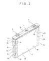
- Portions of the overlapping third sections 23, 23 close to the open end are sealed, for example heat-sealed by point sealing (cf., symbol S in FIG. 2 ).
- point sealing cf., symbol S in FIG. 2
- the sheet 20 is formed into the shape of a thin container and is prevented from unfolding.
- the electrode assembly 4 is inserted into the sheet 20 formed into the thin container. It should be noted that the entire length of the third sections 23 may be sealed.
- the electrode assembly 4 may be placed in the sheet 20 when it is folded into a U-shape as seen from the side, so as to be sandwiched between the second sections 22, 22.
- the electrode assembly 4 may be placed on the first section 21 and then the second sections 22, 22 may be folded so that the electrode assembly 4 is sandwiched between the second sections 22, 22.
- the third sections 23, 23, ... are folded so that the third section 23, 23 overlap each other along the vertical part of the current collector 8.
- portions of the overlapping third sections 23, 23 on the open end side are sealed, for example heat-sealed together by point sealing while using the intermediate part 8b of the current collector 8 as a pad (cf., symbol S in FIG. 2 ). This prevents the sheet 20 from unfolding.
- the two flaps 25, 25 project from the second section 22 of the sheet 20 enclosing the electrode assembly 4.
- Each flap 25 is inserted in the gap between the connection part 8a of the current collector 8 and the electrode assembly 4.
- a blank part 29 is provided between the two flaps 25, 25 so that the gas discharge vent 3 is not covered by the flaps 25, 25.
- the projecting parts 24, 24 project from the first section 21.
- the electrode assembly 4 covered with the sheet 20 in this manner is inserted into the case body 1a.
- the projecting parts 24, 24 are forcedly bent by the edges of the opening of the case body 1a to overlap the third sections 23, 23 and become part of the side surfaces 2c of the insulating cover 2.
- the provision of the beveled parts 2d near the bottom surface part 2a of the insulating cover 2 facilitates smooth insertion into the case body 1a.
- the electrode assembly 4 is smoothly inserted into the case body 1a.
- the embossing E applied to the surface of the sheet of the insulating cover 2 reduces the contact friction between the inner walls of the case body 1a and the insulating cover 2. Accordingly, the electrode assembly 4 can be smoothly inserted into the case body 1a.
- the edges 2e, ... of the insulating cover 2 are in contact with (the edges of) the inner walls of the case body 1a when the electrode assembly 4 is fully housed in the case body 1a.
- the end surface parts 2c of the insulating cover 2 are sandwiched between the edge plates of the case body 1a and (the vertical parts of) the current collector 8 in tight or substantially tight contact. Accordingly, the electrode assembly 4 is positioned in place in the case body 1a when housed in the case body 1a. Consequently, the cover plate 1b can be easily joined to the opening of the case body 1a during manufacturing of the battery cell.
- the beveled parts 2d, ... are provided in the portions of the edges 2e, ... between the adjacent side surfaces of the insulating cover 2 that are near the bottom of the insulating cover 2. This facilitates smooth insertion of the electrode assembly 4 into the case body 1a. Furthermore, when the electrode assembly 4 covered with the insulating cover 2 is housed in the case body 1a, the edges 2e, ... of the insulating cover 2 at which the adjacent side surfaces meet each other are in contact with the inner surfaces of the case body 1a, except the beveled parts 2d, .... Accordingly, the electrode assembly 4 can be positioned in place in the case body 1a when housed in the case body 1a.
- the insulating cover 2 is formed by folding the insulating sheet 20. This allows the electrode assembly 4 to be easily covered (enclosed).
- the overlapping third sections 23, 23 are sealed together. This prevents the sheet 20 formed into a predetermined shape from unfolding. Because the sheet 20 does not unfold, the electrode assembly 4 covered with the sheet 20 can be easily inserted into the case body 1a.
- the flaps 25 of the insulating cover 2 are inserted in the gap formed between the electrode assembly 4 and the first connection parts 8a of the current collector 8 (more specifically, the lower parts of the rivets 12 functioning as auxiliary terminals).
- the buffering effect of the flaps 25 can prevent damage and a short circuit of the electrode assembly 4 if the battery cell is so vigorously vibrated that the lower parts of the auxiliary terminals 12 and the electrode assembly 4 may hit against each other.
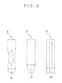
- the vertical part of the current collector 8 has a wide portion 8d at the lower end (tip part) as illustrated in the left-hand part of FIG. 6 .
- the lower end (tip part) of the current collector 8 gradually narrows from the wide portion 8d.
- Each of the beveled parts 2d of the insulating cover 2 is located nearer to the bottom of the case body 1a than the wide portion 8d. Accordingly, the wide portion 8d of the current collector 8 does not hit the inner surfaces of the beveled parts 2d of the insulating cover 2. Therefore, the electrode assembly 4 connected with the current collector 8 can be easily inserted into the insulating cover 2.
- This advantageous effect is also produced by the shape of a current collector 8' (wide portion 8d') illustrated in the middle part of FIG. 6 and the shape of a current collector 8" (wide portion 8d") illustrated in the right-hand part of FIG. 6 .
- the insulating cover 2 may be configured to be housed in the case body 1a without heat-sealing the overlapping third sections 23, 23.
- the third sections 23, 23 do not necessarily need to be sealed together.
- the third sections 23, 23 may be adhered to each other.
- the embossing E is not essential.
- the insulating cover 2 does not necessarily need to be formed from a sheet 20 like the one illustrated in FIG. 3 . Furthermore, if the gas discharge vent 3 is provided in a plate of the case body 1a rather than in the cover plate 1b, one elongated flap 25 may be provided rather than the two flap 25.
- the shape of the case body 1a does not necessarily need to be a flat rectangular box shape one side of which is longer than the other: the case body 1a may have the shape of a square box.
- the electrode assembly is not limited to the winding type having the shape of an ellipsoidal cylinder described above; the electrode assembly may have any shape and may be of multilayered type.
- the present invention is not limited to lithium-ion secondary battery cells.
- the present invention can be applied to various secondary battery cells and primary battery cells, and capacitors such as electrical double layer capacitors.
Landscapes
- Chemical & Material Sciences (AREA)
- Chemical Kinetics & Catalysis (AREA)
- Electrochemistry (AREA)
- General Chemical & Material Sciences (AREA)
- Engineering & Computer Science (AREA)
- Power Engineering (AREA)
- Microelectronics & Electronic Packaging (AREA)
- Inorganic Chemistry (AREA)
- Sealing Battery Cases Or Jackets (AREA)
- Cell Separators (AREA)
- Secondary Cells (AREA)
- Connection Of Batteries Or Terminals (AREA)
Abstract
Description
- The present invention relates to an electric storage device, wherein an electrode assembly to be housed in a case is covered with an insulating cover, which insulates the electrode assembly from the case.
- In recent years, rechargeable and dischargeable electric storage devices such as battery cells (e.g., a lithium ion battery cell and a nickel-metal hydride battery cell) and capacitors (e.g., an electric double layer capacitor) have been adopted as the power sources of vehicles (e.g., an automobile and a motorcycle) and various devices (e.g., a portable terminal and a laptop computer). For example, various energy-dense lithium secondary battery cells available as a power source for electric vehicles or the like. A lithium secondary battery cell includes an electrode assembly housed in a metal case, electrode terminals projecting from inside the case to the outside of the case, a current collector which interconnects the electrode assembly and electrode terminals, and an insulating cover disposed between the case and the electrode assembly to insulate them.
- Patent Document 1 (
JP-A-2009-26704 electrode assembly 120 is inserted in theinsulating cover 110 having the shape of a bag with anopening 111, is then placed in aninterior space 131 formed in thecase 130 and is supported by the inner walls of thecase 130 via theinsulating cover 110 as illustrated inFIG. 7 . - Projecting
sides insulating cover 110 by pressing both sides of theinsulating cover 110 from two sides to integrate them together. Accordingly, the two projectingsides 112 of theinsulating cover 110 come into contact with the inner walls of thecase 130. This reduces friction resistance caused when theinsulating cover 110 is inserted into thecase 130. - In the battery cell described in Patent Document 1, spaces as wide as the widths of the projecting
sides 112 are formed inside thecase 130 by the provision of the projectingsides 112 of theinsulating cover 110. Furthermore, the spaces are formed to be longer than the projectingsides 112 so that the lower edges of the projectingsides 112 do not hit the inner walla of the 130 when theelectrode assembly 120 housed in theinsulating cover 110 is inserted thecase 130. - Accordingly, in the battery cell described in Patent Document 1 described above, the
electrode assembly 120 is not positioned in place inside thecase 130 simply by inserting theelectrode assembly 120 into thecase 130. Consequently, theelectrode assembly 120 can tilt so that the front and rear surfaces are at an angle with respect to the front and rear surfaces of thecase 130. In that case, the cover plate of thecase 130 to which theelectrode assembly 120 is attached through the current collector does not fit the opening of the case body of thecase 130. Accordingly, attaching the cover plate to the opening of the case body of thecase 130 becomes considerably troublesome. This problem can occur with a capacitor (such as an electric double layer capacitor) as well. - An object of the present invention is to provide an electric storage device designed so that an electrode assembly covered with an insulating cover can be smoothly inserted into a case and the electrode assembly is housed and positioned in place in the case.
- An electric storage device according to the present invention includes:
- an electrode assembly;
- an insulating cover covering the electrode assembly; and
- a case comprising a case body having a rectangular box shape and having an opening, the case body being configured to house the electrode assembly and the insulating cover;
- wherein the insulating cover is formed into a rectangular box shape conforming to the body; and
- a portion of each of edges at which adjacent side surfaces of the insulating cover meet each other is beveled into a beveled part, the portion being close to the bottom of the insulating cover,
- In an embodiment of the present invention, the electric storage device may be configured in such a manner that:
- the insulating cover includes: a bottom surface part; and a pair of opposed principal surface parts and a pair of opposed edge surface parts, the principal surface parts and the edge surface parts rising from end edges of the bottom surface part; and
- the insulating cover is formed by folding an insulating sheet.
- In this case, the insulating sheet may include:
- a first section that forms the bottom surface part;
- a pair of second sections, projecting from a pair of opposed end edges of the first section, the pair of second the sections forming the pair of principal surface parts; and
- a pair of third sections forming the pair of edge surface parts, each of the third sections projecting from one of a pair of opposed side edges of at least one of the pair of second sections.
- Furthermore, in this case, the insulating sheet may have a boundary between the second section and the third section, a portion of the boundary close to the first section having a fold that forms the beveled part.
- Furthermore, in this case, the fold may be provided in plural, which are aligned parallel to each other along the boundary.
- In another embodiment of the electric storage device according to the present invention, each of the pair of third sections may include a piece of the third section projecting from one of the pair of second sections and another piece of the third section projecting from the other of the pair of second sections; and
the two pieces of the third section may overlap each other. - In this case, the overlapping two pieces of the third section may be joined together.
- Furthermore, in this case, the overlapping two pieces of the third section may be joined together at a portion opposite from the first section.
- In still another embodiment of the present invention, the electric storage device may further include
- a current collector connected to the electrode assembly, the current collector together with the electrode assembly being covered with the insulating cover,
- wherein the insulating sheet further includes a flap projecting from an end edge of at least one of the pair of second sections, the flap to be inserted into a gap formed between the current collector and the electrode assembly, the gap being at the opening of the case body.
- In yet another embodiment of the electric storage device according to the present invention, embossing may be applied to the insulating sheet entirely or partially.
- In another of the invention, the electric storage device may further includes:
- first and second current collectors connected to the electrode assembly, the first and second current collectors together with the electrode assembly being covered with the insulating cover,
- wherein the electrode assembly includes a positive electrode plate and a negative electrode plate which are insulated from each other;
- the first current collector is connected to the positive electrode plate and the second current collector is connected to the negative electrode plate; and
- each of the pair of edge surface parts of the insulating cover may be sandwiched between an inner surface of the case body and a corresponding one of the pair of current collectors.
- In still another embodiment of the present invention, the electric storage device may further include:
- a current collector connected to the electrode assembly, the current collector together with the electrode assembly being covered with the insulating cover,
- wherein the beveled part is located closer to the bottom of the case body than a wide portion of the current collector.
-
-
FIG. 1 is a cross-sectional front view of a battery cell according to the present invention. -
FIG. 2 is a perspective view of an essential portion of the battery cell; -
FIG. 3 is a plan view of a sheet to be made into an insulating cover which is included in the battery cell; -
FIG. 4 is an enlarged view of embossing on the insulating cover; -
FIG. 5 is an exploded perspective view of the battery cell; -
FIG. 6 is front views of various forms of a current collector which is included in the battery cell; and -
FIG. 7 is an exploded perspective view schematically illustrating a conventional battery cell. - A battery cell which is an embodiment of an electric storage device according to the present invention will be described below with reference to drawings. The battery cell according to this embodiment is a nonaqueous electrolyte secondary battery cell, more specifically, a lithium-ion secondary battery cell. As illustrated in
FIG. 1 , the battery cell according to this embodiment includes a case 1 made up of a case body 1a and acover plate 1b which covers and seals an opening of the case body 1a. Aterminal structure 9 which is electrically connected to anelectrode assembly 4 housed in the case 1 are provided in thecover plate 1b. - The case body la and the
cover plate 1b of the case 1 are made of a metal such as an aluminum alloy or steel. The case body 1a has the shape of a rectangular box that is flat in the width direction, designed to house the windingtype electrode assembly 4 having the shape of an ellipsoidal cylinder. Thecover plate 1b is a rectangular plate that fits the opening of the case body 1a. Thecover plate 1b is fitted into the opening of the case body 1a and sealed and fixed by laser welding or other technique. Agas discharge vent 3 is provided in the center of thecover plate 1b. - In the electrode assembly. 4, a band-qhaped
positive electrode plate 5 and a band-shapednegative electrode plate 6 which are displaced to each other in different lateral directions with a band-shaped separator 7 sandwiched therebetween are wound about a lateral rotation axis into a cylinder in the shape of a vertically long ellipse. Theelectrode assembly 4 is entirely covered with an insulating cover comprising an insulating sheet and is stored in the casing 1 while being insulated from the casing 1. - The
positive electrode plate 5 includes aluminum foil carrying a positive electrode active material at the surface. Thenegative electrode plate 6 includes copper foil carrying a negative electrode active material at the surface. Thepositive electrode plate 5 and thenegative electrode plate 6 each have a non-overlapped portion not coated with the active material at an edge in the lateral direction in which the sheet is displaced. With this arrangement, at the lateral ends of theelectrode assembly 4, the aluminum foil and copper foil are exposed, and thus these metal foils of the positive electrode and negative electrode project from the overlapped portion in a wound configuration. - Metal foils projecting at the lateral ends of the
electrode assembly 4 are electrically connected to respectivecurrent collectors 8. Thecurrent collectors 8 are a conductive metal member bent into a vertically long L-shape. More specifically, thecurrent collector 8 for the positive electrode comprises aluminum or an aluminum alloy, and thecurrent collector 8 for the negative electrode comprises copper or a copper alloy. The horizontal portion of thecurrent collector 8 is afirst connection part 8a. A gap is provided between theconnection part 8a and theelectrode assembly 4. The vertical portion of thecurrent collector 8 is made up of an upper,intermediate part 8b and asecond connection part 8c which are continuos with each other. - The
second connection part 8c is one that is two-forked and bent to a right angle in such a manner that the edges face theelectrode assembly 4, or is one in which an opening is provided and two ridges are provided in such a manner that the edges face theelectrode assembly 4. Thesecond connection part 8c, together with an end of theelectrode assembly 4, is clamped by a clamp plate, not shown, and is connected and fixed by ultrasonic welding or other technique. - The
terminal structure 9 includes a positiveelectrode terminal structure 9 and a negativeelectrode terminal structure 9. Eachterminal structure 9 includes aplastic plate 10, anouter gasket 11 internally and externally disposed to surround each of through-holes 1c formed at each of right and left ends of thecover plate 1b, arivet 12 inserted into each throughhole 1c through theplastic plate 10 and theouter gasket 11 and electrically connected to theconnection part 8a of thecurrent collector 8, aterminal retainer 13 disposed close to theouter gasket 11, aterminal bolt 14 disposed on the outer surface of thecover plate 1b through theterminal retainer 13, and aconnection plate 15 which electrically interconnects theterminal bolt 14 and therivet 12. This arrangement electrically connects theelectrode assembly 4 in the case 1 to theterminal bolt 14. - The
plastic plate 10, theouter gasket 11 and theterminal retainer 13 represent an insulating member. In particular, the outer gasket 11 (and theplastic plate 10 in some instances) also has a sealing function and therefore represents an insulating and sealing member. Therivet 12 represents an auxiliary terminal. Theterminal bolt 14 represents an external terminal. Theconnection plate 15 represents connection conductor. However, theterminal retainer 13 may not have insulating properties. When aluminum or an aluminum allay is us a material for the case 1, theterminal retainer 13 of the positive electrode may be non-isolated so that the potential of the positive electrode may be identical with the potential of the case 1. This suppresses corrosion of the case 1. When iron or stainless steel is used as a material for the case 1, theterminal retainer 13 of the negative electrode may be non-isolated so that the potential of the negative electrode may be identical with the potential of the case 1. - The insulating
cover 2 will now be described with reference toFIG. 2 . The insulatingcover 2 includes a rectangular bottom surface part 2a between the bottom plate of the case body 1a and the bottom of theelectrode assembly 4, a pair of opposedprincipal surface parts edge surface parts principal surface 2b and eachedge surface part 2c of the insulatingcover 2 that is near the bottom constitutes abeveled part 2d. The boundary between eachprincipal surface 2b and eachedge surface 2c except thebeveled part 2d is a sharp edge (unbeveled part) 2e. For example, thebeveled part 2d is 13% of the boundary between theprincipal surface 2b and theedge surface 2c and thesharp edge 2e is 87% of the boundary between theprincipal surface 2b and theedge surface 2c. The bottom surface part 2a constitutes the bottom of the insulatingcover 2. The pair ofprincipal surface parts surfaces cover 2. - The insulating
cover 2 is formed from asheet 20 illustrated inFIG. 3 . Thesheet 20 includes a rectangular section (hereinafter to as the "first sscticu")21 that forms the bottom surface part 2a, section (hereinafter referred to as the "second sections") 22, 22 that project from a pair of opposed end edges (boundaries) 20a, 20a at the longer sides of thefirst section 21 and form theprincipal surface parts parts first section 21, sections (hereinafter referred to as the "third sections") 23, 23 that project from the bothside edges second sections 22 and forms theedge surface parts flaps outer edge 20d of one of thesecond sections - The
first section 21 has the same size as the inner surface of the bottom plate of the case body 1a. Each of thethird sections 23 has the same width as the inner surface of the edge plate of the case body 1a. The length of each of the projectingparts 24 projecting from thefirst section 21 is equal to the width of thethird section 23. - The width of each of the
flaps 25 projecting from theouter edge 20d of one of thesecond sections 22 is smaller than the width of thefirst section 21. It should be noted that theflaps 25 do not necessarily need to project from one of thesecond sections 22; although not depicted, one of theflaps 25 may project from one of thesecond section 22 and theother flap 25 may project from the othersecond section 22, provided that the twoflaps 25 are paired correspondingly to the positive electrode and negativeelectrode terminal structures 9 and ablank part 29 is provided between theflaps 25. - Two
folds 26a, 26b are formed on thefirst section 21 side of the boundary between thesecond section 22 and thethird section 23 to provide thebeveled part 2d. Thefolds 26a, 26b are formed along the boundary. The number of the folds is not limited to two. What is required is that a plurality offolds 26b, ... are provided so that thebeveled part 2d is formed, Anotch 27 is formed from between thethird section 23 and the projectingpart 24 to the folds 26a formed in thesecond section 22. A tear-preventingcut 28 is formed at the boundary between theflap 25 and thesecond section 22 to prevent thesheet 20 from being torn. - As illustrated in
FIG. 4 , embossing E is applied to one or both of the surfaces of thesheet 20 entirely or partially. The embossing E is applied in such a manner that ridges Eb are extended from points of each protuberance Ea having the shape of a quadrangular frustum pyramid. Furthermore, the embossing E can be accomplished on both surfaces of thesheet 20 by depressing portions of thesheet 20 from one side and then depressing the regions adjacent to the portions from the other side. - It should be noted that when the unfolded
sheets 20 are stacked and stored, the embossing E applied to one or both side of thesheets 20 prevents the stackedsheets 20 from stricking to each other. To prevent sticking, the embossing E needs to be applied to only one side of the sheet. However, preferably the embossing E is applied to both sides because thesheet 20 is likely to curl if only one side is embossed. - As illustrated in
FIG. 5 , thesheet 20 is folded along the boundaries 20a, 20a between thefirst section 21 and thesecond sections third section 23 projecting from one of thesecond sections 22 is folded theside edge 20c and thethird section 23 projecting from the othersecond section 22 is folded along theside edge 20c, then thethird section 23 projecting from one of thesecond sections 22 and thethird sections 23 projecting from the othersecond section 22 overlap each other. When thethird sections 23 are folded, the third sections and thesecond sections 22 are also folded along thefolds 26a, 26b to form thebeveled parts 2d. - Portions of the overlapping
third sections FIG. 5 ), that is, portions of the overlappingthird sections beveled parts 2d, are sealed, for example heat-sealed by point sealing (cf., symbol S inFIG. 2 ). As a result, thesheet 20 is formed into the shape of a thin container and is prevented from unfolding. Theelectrode assembly 4 is inserted into thesheet 20 formed into the thin container. It should be noted that the entire length of thethird sections 23 may be sealed. - Alternatively, the
electrode assembly 4 may be placed in thesheet 20 when it is folded into a U-shape as seen from the side, so as to be sandwiched between thesecond sections electrode assembly 4 may be placed on thefirst section 21 and then thesecond sections electrode assembly 4 is sandwiched between thesecond sections third sections third section current collector 8. Then, portions of the overlappingthird sections intermediate part 8b of thecurrent collector 8 as a pad (cf., symbol S inFIG. 2 ). This prevents thesheet 20 from unfolding. - In any of the cases, the two
flaps second section 22 of thesheet 20 enclosing theelectrode assembly 4. Eachflap 25 is inserted in the gap between theconnection part 8a of thecurrent collector 8 and theelectrode assembly 4. Ablank part 29 is provided between the twoflaps gas discharge vent 3 is not covered by theflaps parts first section 21. - The
electrode assembly 4 covered with thesheet 20 in this manner is inserted into the case body 1a. As theelectrode assembly 4 is inserted, the projectingparts third sections cover 2. The provision of thebeveled parts 2d near the bottom surface part 2a of the insulatingcover 2 facilitates smooth insertion into the case body 1a. Thus, theelectrode assembly 4 is smoothly inserted into the case body 1a. - Furthermore, the embossing E applied to the surface of the sheet of the insulating
cover 2 reduces the contact friction between the inner walls of the case body 1a and the insulatingcover 2. Accordingly, theelectrode assembly 4 can be smoothly inserted into the case body 1a. - The
edges 2e, ... of the insulatingcover 2 are in contact with (the edges of) the inner walls of the case body 1a when theelectrode assembly 4 is fully housed in the case body 1a. Theend surface parts 2c of the insulatingcover 2 are sandwiched between the edge plates of the case body 1a and (the vertical parts of) thecurrent collector 8 in tight or substantially tight contact. Accordingly, theelectrode assembly 4 is positioned in place in the case body 1a when housed in the case body 1a. Consequently, thecover plate 1b can be easily joined to the opening of the case body 1a during manufacturing of the battery cell. - As has been described above, in the battery cell according to this embodiment, the
beveled parts 2d, ... are provided in the portions of theedges 2e, ... between the adjacent side surfaces of the insulatingcover 2 that are near the bottom of the insulatingcover 2. This facilitates smooth insertion of theelectrode assembly 4 into the case body 1a. Furthermore, when theelectrode assembly 4 covered with the insulatingcover 2 is housed in the case body 1a, theedges 2e, ... of the insulatingcover 2 at which the adjacent side surfaces meet each other are in contact with the inner surfaces of the case body 1a, except thebeveled parts 2d, .... Accordingly, theelectrode assembly 4 can be positioned in place in the case body 1a when housed in the case body 1a. - In the battery cell according to this embodiment, the insulating
cover 2 is formed by folding the insulatingsheet 20. This allows theelectrode assembly 4 to be easily covered (enclosed). - In the battery cell according to this embodiment, the overlapping
third sections sheet 20 formed into a predetermined shape from unfolding. Because thesheet 20 does not unfold, theelectrode assembly 4 covered with thesheet 20 can be easily inserted into the case body 1a. - Portions of the overlapping
third sections third section first sections 21, are sealed. Accordingly, thethird section 23 projecting from one of thesecond sections 22 and thethird section 23 projecting from the othersecond section 22 are out of line with each other in the direction of the width of theedge surface 2c when overlapping and being sealed, making the width of theedge surface parts 2c of the insulatingcover 2 larger than the inside width of the case body 1a. Consequently, elastic resilience in the width direction is added to the insulatingcover 2. This ensures the contact of the insulatingcover 2 with the inner surfaces of the case body 1a. - Furthermore, in the battery cell according to this embodiment, the
flaps 25 of the insulatingcover 2 are inserted in the gap formed between theelectrode assembly 4 and thefirst connection parts 8a of the current collector 8 (more specifically, the lower parts of therivets 12 functioning as auxiliary terminals). Thus, the buffering effect of theflaps 25 can prevent damage and a short circuit of theelectrode assembly 4 if the battery cell is so vigorously vibrated that the lower parts of theauxiliary terminals 12 and theelectrode assembly 4 may hit against each other. - The vertical part of the
current collector 8 has awide portion 8d at the lower end (tip part) as illustrated in the left-hand part ofFIG. 6 . The lower end (tip part) of thecurrent collector 8 gradually narrows from thewide portion 8d. Each of thebeveled parts 2d of the insulatingcover 2 is located nearer to the bottom of the case body 1a than thewide portion 8d. Accordingly, thewide portion 8d of thecurrent collector 8 does not hit the inner surfaces of thebeveled parts 2d of the insulatingcover 2. Therefore, theelectrode assembly 4 connected with thecurrent collector 8 can be easily inserted into the insulatingcover 2. This advantageous effect is also produced by the shape of a current collector 8' (wide portion 8d') illustrated in the middle part ofFIG. 6 and the shape of acurrent collector 8" (wide portion 8d") illustrated in the right-hand part ofFIG. 6 . - The present invention is not limited to the embodiments described above; various modifications may be made without departing from the spirit of the present invention.
- For example, the insulating
cover 2 may be configured to be housed in the case body 1a without heat-sealing the overlappingthird sections third sections third sections - The insulating
cover 2 does not necessarily need to be formed from asheet 20 like the one illustrated inFIG. 3 . Furthermore, if thegas discharge vent 3 is provided in a plate of the case body 1a rather than in thecover plate 1b, oneelongated flap 25 may be provided rather than the twoflap 25. - The shape of the case body 1a does not necessarily need to be a flat rectangular box shape one side of which is longer than the other: the case body 1a may have the shape of a square box.
- The electrode assembly is not limited to the winding type having the shape of an ellipsoidal cylinder described above; the electrode assembly may have any shape and may be of multilayered type.
- While the embodiments have been described with respect to a lithium-ion battery cell, the present invention can be applied to battery cells of any type and size (eapacity).
- The present invention is not limited to lithium-ion secondary battery cells. The present invention can be applied to various secondary battery cells and primary battery cells, and capacitors such as electrical double layer capacitors.
Claims (12)
- An electric storage device comprisingan electrode assembly (4);an insulating cover (2) covering the electrode assembly (4); anda case (1) comprising a case body (1a) having a rectangular box shape and having an opening, the case body being configured to house the electrode assembly (4) and the insulating cover (2);wherein the insulating cover (2) is formed into a rectangular box shape conforming to the case body (1a); anda portion of each of edges (2e) at which adjacent side surfaces of the insulating cover (2) meet each other is beveled into a beveled part (2d), the portion being close to the bottom of the insulating cover (2).
- The electric storage device according to claim 1, wherein the insulating cover (2) comprises:a bottom surface part (2a); anda pair of opposed principal surface parts (2b, 2b) and a pair of opposed edge surface parts (2c, 2c), the principal surface parts (2b, 2b) and the edge surface parts (2c, 2c) rising from end edges of the bottom surface part (2a), andthe insulating cover (2) is formed by folding an insulating sheet (20).
- The electric storage device according to claim 2, wherein the insulating sheet (20) comprises:a first section (21) that forms the bottom surface part (2a);a pair of second sections (22, 22), projecting from a pair of opposed end edges of the first section (21), the pair of second sections (22, 22) forming the pair of principal surface parts (2b, 2b); anda pair of third sections (23, 23) forming the pair of edge surface parts (2c, 2c), each of the third sections (23) projecting from one of a pair of opposed side edges of at least one of the pair of second sections (22).
- The electric storage device according to claim 3, wherein the insulating sheet (20) has a boundary between the second section (22) and the third section (23), a portion of the boundary close to the first section (21) having a fold that forms the beveled part (2d).
- The electric storage device according to claim 4, wherein the fold is provided in plural (26a, 26b), which are aligned parallel to each other along the boundary.
- The electric storage device according to claim 3, wherein each of the pair of third sections (23, 23) comprises a of the third section (23) projecting from one of the pair of second sections (22) another piece of the third section (23) projecting from the other of the pair of second sections (22); and
the two pieces of the third section (23, 23) overlap each other. - The electric storage device according to claim 6, wherein the overlapping two pieces of the third section (23, 23) are joined together.
- The electric storage device according to claim 7, wherein the overlapping two pieces of the third section (23, 23) are joined together at a portion opposite from the first section (21).
- The electric storage device according to any one of claims 3 to 8, further comprising:a current collector (8) electrically connected to the electrode assembly (4), the current collector (8) together with the electrode assembly (4) being covered with the insulating cover (2),wherein the insulating sheet (20) further comprises a flap (25) projecting from an end edge of at least one of the pair of second sections (22), the flap (25) to be inserted into a gap formed between the current collector (8) and the electrode assembly (4), the gap being at the opening of the case body (1a).
- The electric storage device according to any one of claims 2 to 9, wherein embossing is applied to the insulating sheet (20) entirely or partially.
- The electric storage device according to any one of claims 2 to 8, further comprising:first and second current collectors (8,8)electrically connected to the electrode assembly (4), the first and second current collectors (8, 8) together with the electrode assembly (4) being covered with the insulating cover (2),wherein the electrode assembly (4) comprises a positive electrode plate (5) and a negative electrode plate (6) which are insulated from each other;the first current collector (8) is connected to the positive electrode plate (5) and the second current collector (8) is connected to the negative electrode plate (6); andeach of the pair of edge surface parts (2c, 2c) of the insulating cover (2) is sandwiched between an inner surface of the case body (1a) and a corresponding one of the first and second current collectors (8, 8).
- The electric storage device according to any one of claims 1 to 11, further comprising:a current collector (8) electrically connected to the electrode assembly (4), the current collector (8) together with the electrode assembly (4) being covered with the insulating cover (2),wherein the beveled part (2d) is located closer to the bottom of the case body (1a) than a wide portion (8d) of the current collector (8).
Applications Claiming Priority (1)
| Application Number | Priority Date | Filing Date | Title |
|---|---|---|---|
| JP2010293134 | 2010-12-28 |
Publications (2)
| Publication Number | Publication Date |
|---|---|
| EP2472632A1 true EP2472632A1 (en) | 2012-07-04 |
| EP2472632B1 EP2472632B1 (en) | 2014-04-30 |
Family
ID=45400991
Family Applications (1)
| Application Number | Title | Priority Date | Filing Date |
|---|---|---|---|
| EP20110195770 Active EP2472632B1 (en) | 2010-12-28 | 2011-12-27 | Electric storage device |
Country Status (5)
| Country | Link |
|---|---|
| US (2) | US9123918B2 (en) |
| EP (1) | EP2472632B1 (en) |
| JP (1) | JP5811456B2 (en) |
| KR (1) | KR101895340B1 (en) |
| CN (2) | CN102544411B (en) |
Cited By (3)
| Publication number | Priority date | Publication date | Assignee | Title |
|---|---|---|---|---|
| EP2787554A1 (en) * | 2013-04-05 | 2014-10-08 | Samsung SDI Co., Ltd. | Secondary battery and method of insulating outer surface of secondary battery |
| WO2019201690A1 (en) * | 2018-04-20 | 2019-10-24 | Robert Bosch Gmbh | Method for wrapping an electrode composite with an insulating foil, and battery cell |
| EP4152486A1 (en) * | 2021-09-21 | 2023-03-22 | Prime Planet Energy & Solutions, Inc. | Battery |
Families Citing this family (40)
| Publication number | Priority date | Publication date | Assignee | Title |
|---|---|---|---|---|
| US9472802B2 (en) * | 2011-07-25 | 2016-10-18 | Samsung Sdi Co., Ltd. | Secondary battery |
| WO2013179765A1 (en) * | 2012-05-30 | 2013-12-05 | オリンパス株式会社 | Imaging device manufacturing method and semiconductor device manufacturing method |
| EP2866279B1 (en) | 2012-06-26 | 2017-08-23 | Kabushiki Kaisha Toyota Jidoshokki | Accumulator device |
| JP6179285B2 (en) * | 2012-10-12 | 2017-08-16 | 株式会社Gsユアサ | Storage element, covering sheet, and container covering method |
| JP5925142B2 (en) * | 2013-02-21 | 2016-05-25 | 日立オートモティブシステムズ株式会社 | Secondary battery |
| CN103128359B (en) * | 2013-03-25 | 2015-04-15 | 天津力神电池股份有限公司 | Battery lead automatic chamfering device |
| KR20140120189A (en) * | 2013-04-02 | 2014-10-13 | 삼성에스디아이 주식회사 | Rechargeable battery and manufacturing method of the same |
| US10014495B2 (en) | 2013-05-15 | 2018-07-03 | Samsung Sdi Co., Ltd. | Rechargeable battery |
| JP2015032386A (en) * | 2013-07-31 | 2015-02-16 | 株式会社豊田自動織機 | Power storage device |
| JP6171720B2 (en) * | 2013-08-22 | 2017-08-02 | 株式会社豊田自動織機 | Power storage device and method for manufacturing power storage device |
| EP3070760B1 (en) * | 2013-11-15 | 2019-02-13 | Hitachi Automotive Systems, Ltd. | Prismatic battery |
| JP5812082B2 (en) * | 2013-11-19 | 2015-11-11 | 株式会社豊田自動織機 | Power storage device |
| JP5812087B2 (en) * | 2013-12-26 | 2015-11-11 | 株式会社豊田自動織機 | Power storage device |
| JP6354982B2 (en) * | 2014-04-24 | 2018-07-11 | トヨタ自動車株式会社 | Nonaqueous electrolyte secondary battery and manufacturing method thereof |
| JP6264196B2 (en) * | 2014-05-30 | 2018-01-24 | 三洋電機株式会社 | Prismatic secondary battery |
| KR102177505B1 (en) | 2014-06-17 | 2020-11-11 | 삼성에스디아이 주식회사 | Rechargeable battery |
| US20150381418A1 (en) * | 2014-06-27 | 2015-12-31 | iPhotonix | Remote Orchestration of Virtual Machine Updates |
| US9979698B2 (en) | 2014-06-27 | 2018-05-22 | iPhotonix | Local internet with quality of service (QoS) egress queuing |
| JP6316440B2 (en) * | 2014-09-03 | 2018-04-25 | 日立オートモティブシステムズ株式会社 | Prismatic secondary battery |
| US10573873B2 (en) | 2014-09-03 | 2020-02-25 | Ford Global Technologies, Llc | Terminal locating feature for a battery assembly |
| JP6369561B2 (en) * | 2014-11-28 | 2018-08-08 | 株式会社豊田自動織機 | Power storage device |
| JP6596938B2 (en) * | 2015-06-02 | 2019-10-30 | 株式会社豊田自動織機 | Power storage device and method for manufacturing power storage device |
| JP6047632B2 (en) * | 2015-06-25 | 2016-12-21 | 日立オートモティブシステムズ株式会社 | Secondary battery |
| JP6743356B2 (en) * | 2015-06-30 | 2020-08-19 | 三洋電機株式会社 | Secondary battery |
| KR102377313B1 (en) * | 2016-01-26 | 2022-03-21 | 엘에스머트리얼즈 주식회사 | Ultra Capacitor Module |
| DE102016201199A1 (en) * | 2016-01-27 | 2017-07-27 | Robert Bosch Gmbh | Method for isolating a battery module |
| US10700314B2 (en) | 2016-03-28 | 2020-06-30 | Contemporary Amperex Technolog Co., Limited | Secondary battery head cover assembly, secondary battery including the same and assembling method thereof |
| CN109037509B (en) * | 2016-03-28 | 2020-10-23 | 宁德时代新能源科技股份有限公司 | Secondary battery top cover assembly, secondary battery containing same and assembling method |
| US10763465B2 (en) | 2016-03-28 | 2020-09-01 | Contemporary Amperex Technology Co., Limited | Secondary battery head cover assembly, secondary battery including the same and assembling method thereof |
| JP6722545B2 (en) * | 2016-08-24 | 2020-07-15 | 株式会社東芝 | Insulation member and secondary battery |
| WO2018131417A1 (en) * | 2017-01-10 | 2018-07-19 | 日立オートモティブシステムズ株式会社 | Rectangular secondary battery |
| JP7015124B2 (en) * | 2017-07-31 | 2022-02-02 | 三洋電機株式会社 | Power storage device and insulation holder |
| CN110636727A (en) * | 2018-06-25 | 2019-12-31 | 蒋亮健 | Box type electrostatic field generator device |
| CN110190340B (en) * | 2019-03-01 | 2024-04-19 | 青海时代新能源科技有限公司 | Secondary battery |
| WO2020177599A1 (en) * | 2019-03-01 | 2020-09-10 | 青海时代新能源科技有限公司 | Secondary battery |
| JP7157789B2 (en) * | 2020-10-20 | 2022-10-20 | プライムプラネットエナジー&ソリューションズ株式会社 | prismatic battery |
| US12102832B2 (en) * | 2021-05-19 | 2024-10-01 | Medtronic, Inc. | Folded headspace insulator |
| CN215989141U (en) * | 2021-05-27 | 2022-03-08 | 宁德时代新能源科技股份有限公司 | Battery cell, battery and power consumption device |
| CN216720178U (en) * | 2022-01-24 | 2022-06-10 | 宁德时代新能源科技股份有限公司 | Battery cell, battery and electric equipment |
| CN116060894B (en) * | 2023-04-06 | 2023-06-16 | 常州瑞德丰精密技术有限公司 | Forming method of battery shell structure |
Citations (3)
| Publication number | Priority date | Publication date | Assignee | Title |
|---|---|---|---|---|
| US20040048149A1 (en) * | 2001-10-30 | 2004-03-11 | Oliver Gross | Battery packaging construction |
| US20070196733A1 (en) * | 2004-10-01 | 2007-08-23 | Lee Hyung B | Pouch type rechargeable battery |
| JP2009026704A (en) | 2007-07-23 | 2009-02-05 | Toyota Motor Corp | Battery |
Family Cites Families (14)
| Publication number | Priority date | Publication date | Assignee | Title |
|---|---|---|---|---|
| DE4241037C1 (en) | 1992-12-05 | 1994-04-28 | Deutsche Automobilgesellsch | Electrical accumulator - comprises outer housing containing set of electrode plates surrounded by insulating container with narrow sides having gas=escape channels formed between raised areas |
| JPH0864199A (en) * | 1994-08-17 | 1996-03-08 | A T Battery:Kk | Battery |
| JPH08115729A (en) * | 1994-10-13 | 1996-05-07 | Japan Storage Battery Co Ltd | Organic electrolyte battery and its manufacture |
| JPH11191515A (en) * | 1997-12-26 | 1999-07-13 | Taiyo Yuden Co Ltd | Electronic component with lead |
| JP4268748B2 (en) * | 2000-10-16 | 2009-05-27 | パナソニック株式会社 | Secondary battery |
| JP4061938B2 (en) | 2001-12-20 | 2008-03-19 | トヨタ自動車株式会社 | Storage element and method for manufacturing the same |
| JP2008037192A (en) * | 2006-08-03 | 2008-02-21 | Hitachi Ltd | Power steering device |
| CN101177183A (en) * | 2006-11-10 | 2008-05-14 | 群康科技(深圳)有限公司 | Glass substrates packing box and packaging combination thereof |
| JP4296522B2 (en) | 2007-08-23 | 2009-07-15 | トヨタ自動車株式会社 | Battery and manufacturing method thereof |
| CN101105608A (en) * | 2007-08-29 | 2008-01-16 | 友达光电股份有限公司 | Backlight module and its light source module and backlight module assemblage method |
| JP5274026B2 (en) * | 2008-01-11 | 2013-08-28 | 三洋電機株式会社 | Square battery |
| JP4359857B1 (en) | 2008-05-13 | 2009-11-11 | トヨタ自動車株式会社 | Square battery |
| JP5257697B2 (en) * | 2009-06-12 | 2013-08-07 | トヨタ自動車株式会社 | battery |
| CN101725713A (en) * | 2010-01-08 | 2010-06-09 | 天津科技大学 | Self-adapting medium pressure reciprocating dynamic sealing device |
-
2011
- 2011-12-21 JP JP2011279842A patent/JP5811456B2/en active Active
- 2011-12-23 US US13/336,961 patent/US9123918B2/en active Active
- 2011-12-26 CN CN201110441397.4A patent/CN102544411B/en active Active
- 2011-12-26 CN CN201610082080.9A patent/CN105591040B/en active Active
- 2011-12-27 EP EP20110195770 patent/EP2472632B1/en active Active
- 2011-12-27 KR KR1020110143077A patent/KR101895340B1/en active IP Right Grant
-
2015
- 2015-08-18 US US14/829,402 patent/US9837642B2/en active Active
Patent Citations (3)
| Publication number | Priority date | Publication date | Assignee | Title |
|---|---|---|---|---|
| US20040048149A1 (en) * | 2001-10-30 | 2004-03-11 | Oliver Gross | Battery packaging construction |
| US20070196733A1 (en) * | 2004-10-01 | 2007-08-23 | Lee Hyung B | Pouch type rechargeable battery |
| JP2009026704A (en) | 2007-07-23 | 2009-02-05 | Toyota Motor Corp | Battery |
Cited By (3)
| Publication number | Priority date | Publication date | Assignee | Title |
|---|---|---|---|---|
| EP2787554A1 (en) * | 2013-04-05 | 2014-10-08 | Samsung SDI Co., Ltd. | Secondary battery and method of insulating outer surface of secondary battery |
| WO2019201690A1 (en) * | 2018-04-20 | 2019-10-24 | Robert Bosch Gmbh | Method for wrapping an electrode composite with an insulating foil, and battery cell |
| EP4152486A1 (en) * | 2021-09-21 | 2023-03-22 | Prime Planet Energy & Solutions, Inc. | Battery |
Also Published As
| Publication number | Publication date |
|---|---|
| KR101895340B1 (en) | 2018-09-05 |
| CN105591040B (en) | 2019-08-09 |
| US9123918B2 (en) | 2015-09-01 |
| EP2472632B1 (en) | 2014-04-30 |
| CN105591040A (en) | 2016-05-18 |
| KR20120075401A (en) | 2012-07-06 |
| JP5811456B2 (en) | 2015-11-11 |
| US20120160559A1 (en) | 2012-06-28 |
| CN102544411B (en) | 2016-03-02 |
| CN102544411A (en) | 2012-07-04 |
| US9837642B2 (en) | 2017-12-05 |
| JP2012151099A (en) | 2012-08-09 |
| US20150357607A1 (en) | 2015-12-10 |
Similar Documents
| Publication | Publication Date | Title |
|---|---|---|
| US9837642B2 (en) | Electric storage device | |
| EP2254176B1 (en) | Rechargeable battery | |
| CN107256801B (en) | Charge storage element | |
| KR100627313B1 (en) | Secondary battery | |
| US9767965B2 (en) | Electric storage device, and electric storage apparatus | |
| JP6414731B2 (en) | Power storage element and power storage device | |
| JP4642010B2 (en) | Conductive plate and battery pack | |
| JP2023011675A (en) | Power storage element | |
| US8530068B2 (en) | Square battery and manufacturing method of the same | |
| KR20130132231A (en) | A stepwise electrode assembly, and a battery cell, battery pack and device comprising the same | |
| US9159501B2 (en) | Electric storage device | |
| JP6045987B2 (en) | Prismatic secondary battery | |
| JP2012146664A (en) | Secondary battery, assembly method thereof and battery pack including the same | |
| EP2560230A1 (en) | Secondary battery with improved safety | |
| EP3018750A1 (en) | Cell | |
| KR102394698B1 (en) | battery pack | |
| JP2019053818A (en) | Power storage element, and power storage device including the same | |
| KR100627296B1 (en) | Secondary battery and terminal assembly using the same | |
| WO2024142444A1 (en) | Rectangular secondary battery | |
| JP2018022596A (en) | Power storage element and method for manufacturing the same | |
| JP2022112412A (en) | Terminal component, secondary battery, and battery pack |
Legal Events
| Date | Code | Title | Description |
|---|---|---|---|
| AK | Designated contracting states |
Kind code of ref document: A1 Designated state(s): AL AT BE BG CH CY CZ DE DK EE ES FI FR GB GR HR HU IE IS IT LI LT LU LV MC MK MT NL NO PL PT RO RS SE SI SK SM TR |
|
| AX | Request for extension of the european patent |
Extension state: BA ME |
|
| PUAI | Public reference made under article 153(3) epc to a published international application that has entered the european phase |
Free format text: ORIGINAL CODE: 0009012 |
|
| 17P | Request for examination filed |
Effective date: 20130102 |
|
| RAP1 | Party data changed (applicant data changed or rights of an application transferred) |
Owner name: GS YUASA INTERNATIONAL LTD. |
|
| GRAP | Despatch of communication of intention to grant a patent |
Free format text: ORIGINAL CODE: EPIDOSNIGR1 |
|
| INTG | Intention to grant announced |
Effective date: 20131126 |
|
| GRAS | Grant fee paid |
Free format text: ORIGINAL CODE: EPIDOSNIGR3 |
|
| GRAA | (expected) grant |
Free format text: ORIGINAL CODE: 0009210 |
|
| AK | Designated contracting states |
Kind code of ref document: B1 Designated state(s): AL AT BE BG CH CY CZ DE DK EE ES FI FR GB GR HR HU IE IS IT LI LT LU LV MC MK MT NL NO PL PT RO RS SE SI SK SM TR |
|
| REG | Reference to a national code |
Ref country code: GB Ref legal event code: FG4D Ref country code: CH Ref legal event code: EP |
|
| REG | Reference to a national code |
Ref country code: AT Ref legal event code: REF Ref document number: 665633 Country of ref document: AT Kind code of ref document: T Effective date: 20140515 |
|
| REG | Reference to a national code |
Ref country code: IE Ref legal event code: FG4D |
|
| REG | Reference to a national code |
Ref country code: DE Ref legal event code: R096 Ref document number: 602011006520 Country of ref document: DE Effective date: 20140612 |
|
| REG | Reference to a national code |
Ref country code: AT Ref legal event code: MK05 Ref document number: 665633 Country of ref document: AT Kind code of ref document: T Effective date: 20140430 |
|
| REG | Reference to a national code |
Ref country code: LT Ref legal event code: MG4D |
|
| REG | Reference to a national code |
Ref country code: NL Ref legal event code: VDEP Effective date: 20140430 |
|
| PG25 | Lapsed in a contracting state [announced via postgrant information from national office to epo] |
Ref country code: NO Free format text: LAPSE BECAUSE OF FAILURE TO SUBMIT A TRANSLATION OF THE DESCRIPTION OR TO PAY THE FEE WITHIN THE PRESCRIBED TIME-LIMIT Effective date: 20140730 Ref country code: LT Free format text: LAPSE BECAUSE OF FAILURE TO SUBMIT A TRANSLATION OF THE DESCRIPTION OR TO PAY THE FEE WITHIN THE PRESCRIBED TIME-LIMIT Effective date: 20140430 Ref country code: FI Free format text: LAPSE BECAUSE OF FAILURE TO SUBMIT A TRANSLATION OF THE DESCRIPTION OR TO PAY THE FEE WITHIN THE PRESCRIBED TIME-LIMIT Effective date: 20140430 Ref country code: CY Free format text: LAPSE BECAUSE OF FAILURE TO SUBMIT A TRANSLATION OF THE DESCRIPTION OR TO PAY THE FEE WITHIN THE PRESCRIBED TIME-LIMIT Effective date: 20140430 Ref country code: IS Free format text: LAPSE BECAUSE OF FAILURE TO SUBMIT A TRANSLATION OF THE DESCRIPTION OR TO PAY THE FEE WITHIN THE PRESCRIBED TIME-LIMIT Effective date: 20140830 Ref country code: BG Free format text: LAPSE BECAUSE OF FAILURE TO SUBMIT A TRANSLATION OF THE DESCRIPTION OR TO PAY THE FEE WITHIN THE PRESCRIBED TIME-LIMIT Effective date: 20140730 Ref country code: NL Free format text: LAPSE BECAUSE OF FAILURE TO SUBMIT A TRANSLATION OF THE DESCRIPTION OR TO PAY THE FEE WITHIN THE PRESCRIBED TIME-LIMIT Effective date: 20140430 Ref country code: GR Free format text: LAPSE BECAUSE OF FAILURE TO SUBMIT A TRANSLATION OF THE DESCRIPTION OR TO PAY THE FEE WITHIN THE PRESCRIBED TIME-LIMIT Effective date: 20140731 |
|
| PG25 | Lapsed in a contracting state [announced via postgrant information from national office to epo] |
Ref country code: AT Free format text: LAPSE BECAUSE OF FAILURE TO SUBMIT A TRANSLATION OF THE DESCRIPTION OR TO PAY THE FEE WITHIN THE PRESCRIBED TIME-LIMIT Effective date: 20140430 Ref country code: RS Free format text: LAPSE BECAUSE OF FAILURE TO SUBMIT A TRANSLATION OF THE DESCRIPTION OR TO PAY THE FEE WITHIN THE PRESCRIBED TIME-LIMIT Effective date: 20140430 Ref country code: SE Free format text: LAPSE BECAUSE OF FAILURE TO SUBMIT A TRANSLATION OF THE DESCRIPTION OR TO PAY THE FEE WITHIN THE PRESCRIBED TIME-LIMIT Effective date: 20140430 Ref country code: HR Free format text: LAPSE BECAUSE OF FAILURE TO SUBMIT A TRANSLATION OF THE DESCRIPTION OR TO PAY THE FEE WITHIN THE PRESCRIBED TIME-LIMIT Effective date: 20140430 Ref country code: PL Free format text: LAPSE BECAUSE OF FAILURE TO SUBMIT A TRANSLATION OF THE DESCRIPTION OR TO PAY THE FEE WITHIN THE PRESCRIBED TIME-LIMIT Effective date: 20140430 Ref country code: LV Free format text: LAPSE BECAUSE OF FAILURE TO SUBMIT A TRANSLATION OF THE DESCRIPTION OR TO PAY THE FEE WITHIN THE PRESCRIBED TIME-LIMIT Effective date: 20140430 Ref country code: ES Free format text: LAPSE BECAUSE OF FAILURE TO SUBMIT A TRANSLATION OF THE DESCRIPTION OR TO PAY THE FEE WITHIN THE PRESCRIBED TIME-LIMIT Effective date: 20140430 |
|
| PG25 | Lapsed in a contracting state [announced via postgrant information from national office to epo] |
Ref country code: PT Free format text: LAPSE BECAUSE OF FAILURE TO SUBMIT A TRANSLATION OF THE DESCRIPTION OR TO PAY THE FEE WITHIN THE PRESCRIBED TIME-LIMIT Effective date: 20140901 |
|
| PG25 | Lapsed in a contracting state [announced via postgrant information from national office to epo] |
Ref country code: EE Free format text: LAPSE BECAUSE OF FAILURE TO SUBMIT A TRANSLATION OF THE DESCRIPTION OR TO PAY THE FEE WITHIN THE PRESCRIBED TIME-LIMIT Effective date: 20140430 Ref country code: RO Free format text: LAPSE BECAUSE OF FAILURE TO SUBMIT A TRANSLATION OF THE DESCRIPTION OR TO PAY THE FEE WITHIN THE PRESCRIBED TIME-LIMIT Effective date: 20140430 Ref country code: BE Free format text: LAPSE BECAUSE OF FAILURE TO SUBMIT A TRANSLATION OF THE DESCRIPTION OR TO PAY THE FEE WITHIN THE PRESCRIBED TIME-LIMIT Effective date: 20140430 Ref country code: CZ Free format text: LAPSE BECAUSE OF FAILURE TO SUBMIT A TRANSLATION OF THE DESCRIPTION OR TO PAY THE FEE WITHIN THE PRESCRIBED TIME-LIMIT Effective date: 20140430 Ref country code: SK Free format text: LAPSE BECAUSE OF FAILURE TO SUBMIT A TRANSLATION OF THE DESCRIPTION OR TO PAY THE FEE WITHIN THE PRESCRIBED TIME-LIMIT Effective date: 20140430 Ref country code: DK Free format text: LAPSE BECAUSE OF FAILURE TO SUBMIT A TRANSLATION OF THE DESCRIPTION OR TO PAY THE FEE WITHIN THE PRESCRIBED TIME-LIMIT Effective date: 20140430 |
|
| REG | Reference to a national code |
Ref country code: DE Ref legal event code: R097 Ref document number: 602011006520 Country of ref document: DE |
|
| PLBE | No opposition filed within time limit |
Free format text: ORIGINAL CODE: 0009261 |
|
| STAA | Information on the status of an ep patent application or granted ep patent |
Free format text: STATUS: NO OPPOSITION FILED WITHIN TIME LIMIT |
|
| PG25 | Lapsed in a contracting state [announced via postgrant information from national office to epo] |
Ref country code: IT Free format text: LAPSE BECAUSE OF FAILURE TO SUBMIT A TRANSLATION OF THE DESCRIPTION OR TO PAY THE FEE WITHIN THE PRESCRIBED TIME-LIMIT Effective date: 20140430 |
|
| 26N | No opposition filed |
Effective date: 20150202 |
|
| REG | Reference to a national code |
Ref country code: DE Ref legal event code: R097 Ref document number: 602011006520 Country of ref document: DE Effective date: 20150202 |
|
| PG25 | Lapsed in a contracting state [announced via postgrant information from national office to epo] |
Ref country code: LU Free format text: LAPSE BECAUSE OF FAILURE TO SUBMIT A TRANSLATION OF THE DESCRIPTION OR TO PAY THE FEE WITHIN THE PRESCRIBED TIME-LIMIT Effective date: 20141227 Ref country code: SI Free format text: LAPSE BECAUSE OF FAILURE TO SUBMIT A TRANSLATION OF THE DESCRIPTION OR TO PAY THE FEE WITHIN THE PRESCRIBED TIME-LIMIT Effective date: 20140430 |
|
| REG | Reference to a national code |
Ref country code: CH Ref legal event code: PL |
|
| REG | Reference to a national code |
Ref country code: IE Ref legal event code: MM4A |
|
| REG | Reference to a national code |
Ref country code: FR Ref legal event code: ST Effective date: 20150831 |
|
| PG25 | Lapsed in a contracting state [announced via postgrant information from national office to epo] |
Ref country code: LI Free format text: LAPSE BECAUSE OF NON-PAYMENT OF DUE FEES Effective date: 20141231 Ref country code: CH Free format text: LAPSE BECAUSE OF NON-PAYMENT OF DUE FEES Effective date: 20141231 Ref country code: IE Free format text: LAPSE BECAUSE OF NON-PAYMENT OF DUE FEES Effective date: 20141227 |
|
| PG25 | Lapsed in a contracting state [announced via postgrant information from national office to epo] |
Ref country code: FR Free format text: LAPSE BECAUSE OF NON-PAYMENT OF DUE FEES Effective date: 20141231 |
|
| PG25 | Lapsed in a contracting state [announced via postgrant information from national office to epo] |
Ref country code: SM Free format text: LAPSE BECAUSE OF FAILURE TO SUBMIT A TRANSLATION OF THE DESCRIPTION OR TO PAY THE FEE WITHIN THE PRESCRIBED TIME-LIMIT Effective date: 20140430 |
|
| PG25 | Lapsed in a contracting state [announced via postgrant information from national office to epo] |
Ref country code: MC Free format text: LAPSE BECAUSE OF FAILURE TO SUBMIT A TRANSLATION OF THE DESCRIPTION OR TO PAY THE FEE WITHIN THE PRESCRIBED TIME-LIMIT Effective date: 20140430 |
|
| PG25 | Lapsed in a contracting state [announced via postgrant information from national office to epo] |
Ref country code: TR Free format text: LAPSE BECAUSE OF FAILURE TO SUBMIT A TRANSLATION OF THE DESCRIPTION OR TO PAY THE FEE WITHIN THE PRESCRIBED TIME-LIMIT Effective date: 20140430 Ref country code: MT Free format text: LAPSE BECAUSE OF FAILURE TO SUBMIT A TRANSLATION OF THE DESCRIPTION OR TO PAY THE FEE WITHIN THE PRESCRIBED TIME-LIMIT Effective date: 20140430 Ref country code: HU Free format text: LAPSE BECAUSE OF FAILURE TO SUBMIT A TRANSLATION OF THE DESCRIPTION OR TO PAY THE FEE WITHIN THE PRESCRIBED TIME-LIMIT; INVALID AB INITIO Effective date: 20111227 |
|
| GBPC | Gb: european patent ceased through non-payment of renewal fee |
Effective date: 20151227 |
|
| PG25 | Lapsed in a contracting state [announced via postgrant information from national office to epo] |
Ref country code: GB Free format text: LAPSE BECAUSE OF NON-PAYMENT OF DUE FEES Effective date: 20151227 |
|
| PG25 | Lapsed in a contracting state [announced via postgrant information from national office to epo] |
Ref country code: MK Free format text: LAPSE BECAUSE OF FAILURE TO SUBMIT A TRANSLATION OF THE DESCRIPTION OR TO PAY THE FEE WITHIN THE PRESCRIBED TIME-LIMIT Effective date: 20140430 |
|
| PG25 | Lapsed in a contracting state [announced via postgrant information from national office to epo] |
Ref country code: AL Free format text: LAPSE BECAUSE OF FAILURE TO SUBMIT A TRANSLATION OF THE DESCRIPTION OR TO PAY THE FEE WITHIN THE PRESCRIBED TIME-LIMIT Effective date: 20140430 |
|
| REG | Reference to a national code |
Ref country code: DE Ref legal event code: R079 Ref document number: 602011006520 Country of ref document: DE Free format text: PREVIOUS MAIN CLASS: H01M0002020000 Ipc: H01M0050100000 |
|
| P01 | Opt-out of the competence of the unified patent court (upc) registered |
Effective date: 20230522 |
|
| PGFP | Annual fee paid to national office [announced via postgrant information from national office to epo] |
Ref country code: DE Payment date: 20231031 Year of fee payment: 13 |