EP2472440B1 - Verfahren und System zur Diagnose des Zustands einer Anlage - Google Patents
Verfahren und System zur Diagnose des Zustands einer Anlage Download PDFInfo
- Publication number
- EP2472440B1 EP2472440B1 EP11150047.6A EP11150047A EP2472440B1 EP 2472440 B1 EP2472440 B1 EP 2472440B1 EP 11150047 A EP11150047 A EP 11150047A EP 2472440 B1 EP2472440 B1 EP 2472440B1
- Authority
- EP
- European Patent Office
- Prior art keywords
- plant
- self
- data
- spatial
- deviation
- Prior art date
- Legal status (The legal status is an assumption and is not a legal conclusion. Google has not performed a legal analysis and makes no representation as to the accuracy of the status listed.)
- Not-in-force
Links
Images


Classifications
-
- G—PHYSICS
- G06—COMPUTING; CALCULATING OR COUNTING
- G06N—COMPUTING ARRANGEMENTS BASED ON SPECIFIC COMPUTATIONAL MODELS
- G06N3/00—Computing arrangements based on biological models
- G06N3/02—Neural networks
- G06N3/08—Learning methods
- G06N3/088—Non-supervised learning, e.g. competitive learning
-
- G—PHYSICS
- G06—COMPUTING; CALCULATING OR COUNTING
- G06N—COMPUTING ARRANGEMENTS BASED ON SPECIFIC COMPUTATIONAL MODELS
- G06N3/00—Computing arrangements based on biological models
- G06N3/02—Neural networks
- G06N3/04—Architecture, e.g. interconnection topology
- G06N3/045—Combinations of networks
-
- G—PHYSICS
- G01—MEASURING; TESTING
- G01N—INVESTIGATING OR ANALYSING MATERIALS BY DETERMINING THEIR CHEMICAL OR PHYSICAL PROPERTIES
- G01N33/00—Investigating or analysing materials by specific methods not covered by groups G01N1/00 - G01N31/00
- G01N33/0098—Plants or trees
Definitions
- the present invention relates to diagnosis of plant status, and in particular, to a method and system for diagnosing plant status by deploying self-organizing maps.
- Fault detection and diagnosis is an important problem in process engineering. Early detection and diagnosis of process faults while the plant is still operating in a controllable region can help avoid abnormal event progression and reduce productivity loss.
- SOM self-organizing maps
- the objective of these maps is to automatically group similar states together.
- the performance of the map depends on several circumstances, among which is the size of the map, the learning rate and learning function, the neighborhood function, the number of training phases, the amount of input data, the weighting of the input data, the quality of the input data and the initial state of the map.
- data is learned unsupervised.
- the final map may be altered by supervised learning.
- a SOM may be trained based on two approaches.
- the SOM is learned using historical process data with state known to be good.
- process data is fed into the map.
- the distance of the input data vector to the best matching neuron in the trained map is calculated. If the distance is greater than a certain threshold, a failure state or unknown state is assumed.
- the SOM is learned using historical process data with known state. The position of the data is being tracked. Nodes which contain bad states are being marked. Accordingly, nodes which contain good states are marked.
- process data is fed into the map. If data is mapped to a node that has been marked as "good”, a good state is assumed. Accordingly, if data is mapped to a node that has been marked as "bad”, a bad state is assumed. What is more, if the distance of the process data from the map is greater than a certain threshold, an unknown state is assumed.
- the document EP 2003604 A1 discloses a method on how to map information items such that similar information items are mapped to similar positions. This results in a reduced storage capacity and the time needed for determining the matching position for the information item.
- the document WO 2009/126815 A2 discloses a method that involves maintaining a self-organizing map (SOM) database containing user preference data entries that include wide range of fields or attributes of user preferences.
- SOM self-organizing map
- a set of SOMs is created by filtering from the SOM database.
- a set of trained SOMs is applied in coordination with each other, where the trained SOMs provide recommendations in response to the queries based upon inter-cooperation of the SOMs trained with respective fields and attributes of user preferences related to respective SOMs.
- the object of the present invention is to reduce the size of self-organizing maps deployed for diagnosis of plant status, while providing an improved accuracy in differentiation between good and bad states.
- the underlying idea of the present invention is that historical process data is evaluated by a self-organizing map wherein such historical process data is grouped in at least one of two ways, namely, time based grouping and spatial grouping.
- a separate self-organizing map is trained for each spatial and/or time based group.
- These self-organizing maps are then deployed to detect faults using current process data.
- the above-mentioned time based and/or spatial grouping provides several advantages.
- the map size of each self-organizing map can be smaller compared to using a single map. Searching the node with the smallest distance during operation can then be performed faster. More importantly, the number of different good states in each map is much smaller than using a single map. Thus, outliers can be identified much easier and more accurate. As described by means of an example provided below, using a small map size is sufficient to detect various types of faults.
- each time based group corresponds to process state and defined by a unique identifier.
- the unique identifier allows for grouping the data by circumstances of the time.
- the spatial grouping is done by extracting engineering data of the plant, said engineering data comprising metadata containing information about logical connections of parts of the plant and information about the signals from different devices in the plant.
- engineering tools such as COMOS PT may be provided with the possibility to extract engineering data as metadata, e.g. XML.
- said spatial grouping comprises using the engineering data to define separating parts in the plant and to group together all parts of the plant between a pair of separating parts, wherein separating parts correspond to parts of the plant where signal or media flow starts or ends.
- separating parts correspond to parts of the plant where signal or media flow starts or ends.
- said spatial grouping comprises using the engineering data to construct signed digraphs and, for each signal on said digraph, identifying and grouping together all related signals.
- digraphs provide coarse relationships which would simplify spatial grouping.
- the step of training said self-organizing maps comprises scaling data corresponding to one or more process tags to a desired interval.
- the step of training said self-organizing maps comprises using a differential quotient for one or more process tags.
- the method further involves determining a cause of said deviation by deploying non-coherent fault trees that are constructed using said engineering data.
- Fault trees contain failure and success events, using AND, OR and NAND logic which can be used to narrow down on a possible cause of failure, i.e., deviation.
- the method further involves determining a cause of said deviation by using signed digraphs that are constructed using said engineering data.
- Signed digraphs feature the advantage of including interconnections, i.e. positive and negative influences between process variables. Additionally, control loops can be considered in the model. Thus, digraphs provide increased efficiency of fault analysis and a narrower picture of possible causes.
- a device connected to the signal causing the largest contribution of the deviation in the self-organizing map is used as a starting point to determine the cause of the deviation.
- the proposed method further comprises notifying said cause of the deviation at a maintenance station.
- a computer program product comprises computer readable program code embodied therein, which, when executed on a computer, carries out the method according the above described embodiments.
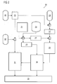
- the illustrated system 1 is a distributed control system comprising a plurality of automation systems 2, including, for example, programmable logic controllers (PLC) that are connected to field devices/actuators 3 by a field bus 4.
- the automation systems 2 communicate process data from these field devices/actuators 3 to one or more operating system (OS) servers 5 via communication network 7, comprising, for example, industrial Ethernet.
- OS operating system
- the process data is accessed from the OS server(s) 5 by one or more OS clients 6 via terminal bus 8.
- a central archive server 12 may be provided for storing historical process data.
- a plant status diagnosis means 13 is provided for diagnosis of plant status based on current and historical process data process data using self-organizing maps (SOM).
- SOM self-organizing maps
- the plant status diagnosis means 13 obtains historical process data and groups the historical process data into at least one of two ways, namely time based groups and spatial groups. Based on the grouping, a separate self-organizing map is then trained for each of the time based groups and/or spatial groups. The trained self-organizing maps are subsequently deployed by feeding the trained self-organizing maps with current process data of the plant. A fault condition is identified when a deployed self-organizing map detects a deviation in the current process data.
- the plant status diagnosis means 13 may further be provided with means for determining a cause of the deviation and means for notifying a deviation and the identified cause to a maintenance station server 10, from which it is accessed by a maintenance station client 11.
- the plant status diagnosis means 13 includes a computer system comprising appropriate software, which when executed, carries out the diagnosis method mentioned above.
- the present invention may be used for both batch and continuous processes.
- the example illustrated in FIG 1 is a batch application, wherein the plant is controlled through different process states by a batch server 9.
- a batch process is a discontinuous process. Typical branches that use batch processes are biotechnology, pharmaceuticals, plastics etc.
- the terminology of batch processes was defined by NAMUR and ISA SP88.
- Batch software is used to create and modify recipes separately from the engineering system of the process control system. Recipes contain set points of the relevant process variables and instructions or procedural rules for production. Normally, several batches are processed at the same time so that some production process cells are in use and not currently available. Before the production can be started the recipes are assigned to the production cell with the required equipment and capacity. During production the process variables change in a wide range. This may lead to decreased performance and quality compared to having a well defined state. Therefore it is necessary to monitor these variables against the ideal profile.
- process state refers to a recipe operation as a step in a batch. Additionally, for plants not featuring a batch system, the term “process state” may be referred to steps of sequential function charts (SFC).
- SFC sequential function charts
- FIG 2 shows an exemplary flowchart 20 illustrating the proposed diagnosis method in greater detail.
- block 21 involves defining a unique identifier for each process state. For a batch process these unique identifiers correspond to recipe operations.
- An exemplary illustration is made referring to FIG 3 , which shows a recipe procedure 50 comprising multiple sub-recipe procedures 51 and each of the sub-recipe procedures 51 comprising one or more recipe operations 52.
- a unique identifier is defined for each recipe operation 52.
- the block 21 may involve defining unique identifiers for steps in a sequential function chart (SFC). Let the unique identifiers defined in block 21 be designated as UID 1, UID 2...UID N.
- historical process data is obtained from process signals 23, including, for example signals from transmitters/actuators, control signals from the distributed control system and additional signals.
- the historical process data may be grouped by circumstances of time, i.e., into time based groups.
- the above-obtained historical data is generally stored in a central archive server.
- the unique identifiers obtained at block 21 may be further stored in a short time archival system, such as an OPC server (block 24).
- process data is also grouped into spatial groups using engineering data.
- engineering data is obtained from an engineering system 26 having an engineering tool such as COMOS PT that features the possibility to extract engineering data as metadata, e.g. XML.
- the metadata contains the logical connection of the parts of the plant as well as information about the signals of the different field devices.
- plant components are grouped into spatial groups using one of two exemplary approaches. In a first approach, separating parts in the plant are defined. Separating parts may be all parts where flow starts or ends, e.g. all vessels.
- the term "flow" may refer to signal flow or media flow (for example, water, gas, etc).
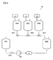
- FIG 4 shows a simplified example of a piping and instrumentation diagram (P&ID) 60 constructed from engineering data.
- P&ID piping and instrumentation diagram
- the first group comprises the vessels B001 and B002 including the parts between said vessels.
- the second group comprises the vessels B002, B004, B005 and B006 including the parts between these vessels and the level transmitters L001, L002 and L003.
- information about separating parts may be obtained using a diagnostic knowledge database 28.
- a second approach for spatial grouping at block 27 includes the use of signed directed graphs (or digraphs). From the engineering data, signed digraphs can automatically be constructed which represent the interrelationships between process variables.
- An introduction to signed digraphs is presented in the document L.M. Bartlett, E.E. Hurdle, E.M. Kelly; Integrated System Fault Diagnostics Utilising Digraph and Fault Tree Based Approaches; Reliability Engineering and System Safety, 2009, vol.94, no.6, p.1107-15 .
- the digraph model features interconnections or influences between variables as well as failure modes. After having constructed the digraph model, for each signal related signals are traced and grouped. The spatial groups thus formed may have a strong overlap. On the one hand, this results in coarse relationships. On the other hand, relationships not foreseen by the digraph model are lost and, additionally, lots of spatial groups may need to be created.
- the spatial groups of the plant components obtained at block 27 are designated herein as SG 1, SG 2, ... SG M.
- historical process data may be grouped based on spatial location of the signals.
- a separate self-organizing map is trained using historical process data. Whether a group is involved in a process state can be deduced, for example from changes of operation conditions, i.e. from the change of control variables (and the groups affected by these actuators) in a process state.
- the various self-organizing maps (SOM) created at step 29 may be designated as:
- the above-mentioned time based and spatial grouping provides several advantages.
- the map size of each self-organizing map can be smaller compared to using a single map. Searching the node with the smallest distance during operation can then be performed faster. More importantly, the number of different good states in each map is much smaller than using a single map. Thus, outliers can be identified much easier and more accurate.
- using a small map size for example, a map of size 2x3, is sufficient to detect various types of faults.
- the SOMs trained at block 29 are deployed during plant operation.
- the different self-organizing maps that are involved a process state are fed with current process data.
- a fault or failure condition is identified.
- a cause is determined for the deviation identified at block 30.
- fault trees or signed digraphs may be deployed. For this, information about devices, their connection and flow direction and connected signals (such as a P&ID) can be obtained from the engineering data extracted at block 25 from engineering tools such as COMOS PT. Further, knowledge about failure states of process and P&ID parts (for fault tree analysis) and knowledge about interconnections or influences between P&ID parts (for signed digraphs) may be obtained from a diagnostic knowledge database 32.
- non-coherent fault trees are automatically constructed using P&ID-metadata and, as diagnostic knowledge, the failure modes of plant components and logical connections between the failure modes.
- Fault trees contain failure and success events, therefore using AND, OR and NAND logic.
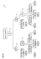
- FIG 5a shows an exemplary fault tree 71 constructed using engineering data and diagnostic knowledge of failure modes and FIGS 5b and 5c show the parts 71a and 71b of the main fault tree 71.
- success or failure event is arrived at by a logical combination of preceding success or failure events using an AND gate 72, an OR gate 73, or a NAND gate 74.
- the device connected to the signal causing the largest contribution of the deviation in the self-organizing map is utilized.
- signed digraphs are constructed for determining the cause of a fault or deviation.
- the device connected to the signal causing the largest contribution of the deviation in the self-organizing map is used.
- signed digraphs feature the advantage of including interconnections, i.e. positive and negative influences between process variables. Additionally, control loops can be considered in the model. Thus, digraphs are more efficient than fault trees. Further, signed digraphs provide a narrower picture of possible causes than fault trees do.
- the identified deviations and/or the possible cause(s) of deviation is/are then displayed plant personnel at a plant maintenance station.
- the illustrated embodiments provide enhanced real-time performance. This is because the map size of each map can be smaller compared to using a single map as a result of which searching the node with the smallest distance during operation can then be performed faster. Further outlier detection accuracy is improved as the number of different good states in each map is much smaller than using a single map, leading to a better signal-to-noise-ratio. Thus, outliers can be identified much easier and more accurate.
- the present invention also provides improved robustness by deploying grouping which results in fault detection for different sizes of maps. Furthermore, faults specific to a spatial group will be identified as such, speeding up fault location and diagnosis. Using engineering data combined with a distributed control system, a system for diagnosis of process plants can automatically be set up.
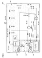
- FIG 6 shows a P&ID 80 for the set up considered in this example.
- two spatial groups namely SG 1 and SG 2
- shaded regions 81 and 82 correspond to the overlap between the spatial groups.
- Table 1 below illustrates the captured signals of FIG 6 and their use.
- Table 2 shows the malfunctions (fault conditions) identified for the use case.
- sccm means standard cubic centimeters per minute and SID refers to malfunction identification number.
- Table 2 No. SID Malfunction name Explanation implementation 1 1 Normal No malfunction Armature KRC-U170 is closed 2 2 Dry run No inflow before the pump 3 3 Blockage Blockage after the pump Regulating valve KVL-U230 is closed (0%) 4 4 Partial blockage Partial blockage after the pump Regulating valve KVL-U230 is set to 10% 5 6 External leakage Outflow in recycling container KV1-U040 is opened 6 7 Internal leakage (small) Backflow from recycling container directly to recycling container KV1-U260 is opened slightly 7 8 Internal leakage (big) Backflow from recycling container directly to recycling container KV1-U260 is opened more 8 9 External leakage (storage) Outflow from reactor to storage KRE-U070 is opened 9 1005 Air Coriolis (500 sccm) Air injection before Coriolis measurement device (500
- the data captured in Table 1 was read into various SOMs.
- the evaluation was done in four ways, namely, a) using a single SOM, b) using multiple SOMs having data grouped by time (i.e., using time based grouping only), c) using multiple SOMs having data grouped by location (i.e., using spatial grouping only), and d) using multiple SOMs having data grouped by time and location (i.e., using both time based grouping and spatial grouping)
- the process of evaluation was implemented in MATLAB and based on an exemplary procedure similar to that disclosed in the document WO 03063017 A2 .
- the time based grouping was done with the help of the UIDs (please refer to Table 3), while the spatial grouping was done based on the spatial groups SG 1 and SG 2, represented by the shaded regions 81 and 82 in FIG 6 .
- the two spatial groups have an overlap, as indicated by the region 83 in the same figure.
- Map sizes from at least 2x3 to 30x40 were computed.
- the training was done with 670 records.
- the test data consisted of 10576 records on the whole.
- the deviation (fault condition) was computed as follows:
Landscapes
- Engineering & Computer Science (AREA)
- Theoretical Computer Science (AREA)
- Physics & Mathematics (AREA)
- Data Mining & Analysis (AREA)
- General Health & Medical Sciences (AREA)
- Biomedical Technology (AREA)
- Biophysics (AREA)
- Computational Linguistics (AREA)
- Life Sciences & Earth Sciences (AREA)
- Evolutionary Computation (AREA)
- Artificial Intelligence (AREA)
- Molecular Biology (AREA)
- Computing Systems (AREA)
- General Engineering & Computer Science (AREA)
- General Physics & Mathematics (AREA)
- Mathematical Physics (AREA)
- Software Systems (AREA)
- Health & Medical Sciences (AREA)
- Testing And Monitoring For Control Systems (AREA)
Claims (14)
- Verfahren (20) zur Zustandsdiagnose einer Prozessanlage, Folgendes umfassend:- Erhalten (22) historischer Prozessdaten der Anlage,- Gruppieren (21, 27) der historischen Prozessdaten in mehrere zeitbasierte Gruppen und mehrere räumliche Gruppen, wobei das räumliche Gruppieren (27) durch Extrahieren (25) von technischen Daten der Anlage vorgenommen wird, wobei die technischen Daten Metadaten umfassen, welche Informationen über logische Verknüpfungen von Anlagenteilen und Informationen über die Signale von verschiedenen Vorrichtungen in der Anlage enthalten, und wobei das räumliche Gruppieren (27) ein Verwenden dieser technischen Daten umfasst, um trennende Teile in der Anlage zu definieren und alle Anlagenteile zwischen einem Paar trennender Teile zusammen zu gruppieren, wobei trennende Teile Anlagenteilen entsprechen, bei welchen ein Signalfluss oder Medienfluss beginnt oder endet,- Trainieren (29) mehrerer selbstorganisierender Abbildungen unter Verwendung der historischen Prozessdaten, wobei jede selbstorganisierende Abbildung einer Kombination aus einer der zeitbasierten Gruppen und einer der räumlichen Gruppen entspricht,- Einsetzen (30) der trainierten selbstorganisierenden Abbildungen unter Anlagenbetrieb, umfassend Speisen der trainierten selbstorganisierenden Abbildungen mit aktuellen Prozessdaten der Anlage, und- Bestimmen eines Fehlerzustands, wenn eine eingesetzte selbstorganisierende Abbildung eine Abweichung in den aktuellen Prozessdaten detektiert.
- Verfahren (20) nach Anspruch 1, wobei jede zeitbasierte Gruppe einem Prozesszustand (53) entspricht und durch eine eindeutige Kennung definiert ist.
- Verfahren (20) nach Anspruch 1 oder 2, wobei das räumliche Gruppieren (27) ein Verwenden der technischen Daten, um mit Vorzeichen versehene Digrafen zu konstruieren, und für jedes Signal auf dem Digrafen ein Identifizieren und Zusammengruppieren aller verwandten Signale umfasst.
- Verfahren (20) nach einem der vorhergehenden Ansprüche, wobei der Schritt des Trainierens (29) der selbstorganisierenden Abbildungen ein Skalieren von Daten entsprechend einer oder mehrerer Prozessmarken zu einem gewünschten Intervall umfasst.
- Verfahren (20) nach einem der vorhergehenden Ansprüche, wobei der Schritt des Trainierens (29) der selbstorganisierenden Abbildungen ein Verwenden eines Differentialquotienten für eine oder mehrere Prozessmarken umfasst.
- Verfahren (20) nach einem der vorhergehenden Ansprüche, weiterhin umfassend ein Bestimmen (31) einer Ursache der Abweichung durch Einsetzen nicht kohärenter Fehlerbäume, welche unter Verwendung der technischen Daten aufgebaut werden.
- Verfahren (20) nach einem der Ansprüche 1 bis 5, weiterhin umfassend ein Bestimmen (31) einer Ursache der Abweichung durch Verwenden mit Vorzeichen versehener Digrafen, welche unter Verwendung der technischen Daten aufgebaut werden.
- Verfahren (20) nach einem der Ansprüche 6 und 7, wobei eine Vorrichtung, welche mit dem Signal verknüpft ist, welches den größten Beitrag zu der Abweichung in der selbstorganisierenden Abbildung bewirkt, als ein Anfangspunkt verwendet wird, um die Ursache der Abweichung zu bestimmen.
- Verfahren (20) nach einem der Ansprüche 6 bis 8, weiterhin umfassend ein Benachrichtigen (33) einer Wartungsstation über die Ursache der Abweichung.
- Computerprogrammprodukt, welches einen computerlesbaren Programmcode umfasst, welcher darin enthalten ist, welcher, wenn er auf einem Computer ausgeführt wird, das Verfahren nach einem der Ansprüche 1 bis 9 ausführt.
- Prozesssteuerungssystem (1) mit einem Diagnosemittel (13) eines Anlagenzustands, wobei das Anlagendiagnosemittel weiterhin Folgendes umfassend:- Mittel zum Erhalten (22) historischer Prozessdaten der Anlage,- Mittel zum Gruppieren (21, 27) der historischen Prozessdaten in mehrere zeitbasierte Gruppen und mehrere räumliche Gruppen, wobei das räumliche Gruppieren (27) durch Extrahieren (25) von technischen Daten der Anlage vorgenommen wird, wobei die technischen Daten Metadaten umfassen, welche Informationen über logische Verknüpfungen von Anlagenteilen und Informationen über die Signale von verschiedenen Vorrichtungen in der Anlage enthalten, und wobei das räumliche Gruppieren (27) ein Verwenden dieser technischen Daten umfasst, um trennende Teile in der Anlage zu definieren und alle Anlagenteile zwischen einem Paar trennender Teile zusammen zu gruppieren, wobei trennende Teile Anlagenteilen entsprechen, bei welchen ein Signalfluss oder Medienfluss beginnt oder endet,- Mittel zum Trainieren (29) mehrerer selbstorganisierender Abbildungen unter Verwendung der historischen Prozessdaten, wobei jede selbstorganisierende Abbildung einer Kombination aus einer der zeitbasierten Gruppen und einer der räumlichen Gruppen entspricht,- Mittel zum Einsetzen (30) der trainierten selbstorganisierenden Abbildungen unter Anlagenbetrieb, umfassend Speisen der trainierten selbstorganisierenden Abbildungen mit aktuellen Prozessdaten der Anlage, und- Mittel zum Bestimmen eines Fehlerzustands, wenn eine eingesetzte selbstorganisierende Abbildung eine Abweichung in den aktuellen Prozessdaten detektiert.
- System (1) nach Anspruch 11, wobei jede zeitbasierte Gruppe einem Prozesszustand (53) entspricht, wobei weiterhin das System (1) Mittel zur Bereitstellung einer eindeutigen Kennung für jeden Prozesszustand (53) umfasst.
- System (1) nach einem der Ansprüche 11 und 12, weiterhin umfassend Mittel zum Bestimmen (31) einer Ursache der Abweichung durch Einsetzen nicht kohärenter Fehlerbäume oder mit Vorzeichen versehener Digrafen, welche unter Verwendung der technischen Daten aufgebaut werden.
- System (1) nach Anspruch 13, weiterhin umfassend ein Mittel zum Benachrichtigen (33) einer Wartungsstation über die Ursache der Abweichung.
Priority Applications (1)
| Application Number | Priority Date | Filing Date | Title |
|---|---|---|---|
| EP11150047.6A EP2472440B1 (de) | 2011-01-04 | 2011-01-04 | Verfahren und System zur Diagnose des Zustands einer Anlage |
Applications Claiming Priority (1)
| Application Number | Priority Date | Filing Date | Title |
|---|---|---|---|
| EP11150047.6A EP2472440B1 (de) | 2011-01-04 | 2011-01-04 | Verfahren und System zur Diagnose des Zustands einer Anlage |
Publications (2)
| Publication Number | Publication Date |
|---|---|
| EP2472440A1 EP2472440A1 (de) | 2012-07-04 |
| EP2472440B1 true EP2472440B1 (de) | 2014-06-25 |
Family
ID=43903960
Family Applications (1)
| Application Number | Title | Priority Date | Filing Date |
|---|---|---|---|
| EP11150047.6A Not-in-force EP2472440B1 (de) | 2011-01-04 | 2011-01-04 | Verfahren und System zur Diagnose des Zustands einer Anlage |
Country Status (1)
| Country | Link |
|---|---|
| EP (1) | EP2472440B1 (de) |
Cited By (2)
| Publication number | Priority date | Publication date | Assignee | Title |
|---|---|---|---|---|
| CN107291063A (zh) * | 2016-04-12 | 2017-10-24 | 西门子公司 | 用于监控技术设施的运行的诊断装置和诊断方法 |
| EP3282399A1 (de) | 2016-08-11 | 2018-02-14 | Siemens Aktiengesellschaft | Verfahren zur verbesserten erkennung von prozessanomalien einer technischen anlage sowie entsprechendes diagnosesystem |
Families Citing this family (6)
| Publication number | Priority date | Publication date | Assignee | Title |
|---|---|---|---|---|
| DE102012015485A1 (de) | 2012-08-07 | 2014-05-15 | Prüftechnik Dieter Busch AG | Verfahren zum Überwachen von rotierenden Maschinen |
| EP3279756B1 (de) * | 2016-08-01 | 2019-07-10 | Siemens Aktiengesellschaft | Diagnoseeinrichtung und verfahren zur überwachung des betriebs einer technischen anlage |
| EP3495900A1 (de) | 2017-12-11 | 2019-06-12 | Siemens Aktiengesellschaft | Optimierung von prozessen mithilfe von selbstorganisierenden karten |
| EP3591482B1 (de) | 2018-07-03 | 2024-06-12 | Siemens Aktiengesellschaft | Überwachung einer technischen anlage |
| EP3764182A1 (de) * | 2019-07-12 | 2021-01-13 | Siemens Aktiengesellschaft | Ring-schlüsse bei fehlerbäumen und normalisierte darstellung |
| CN111814108B (zh) * | 2020-01-10 | 2024-04-12 | 北京航天测控技术有限公司 | 一种基于自组织神经网络的连接型间歇故障诊断方法 |
Family Cites Families (5)
| Publication number | Priority date | Publication date | Assignee | Title |
|---|---|---|---|---|
| US6965885B2 (en) | 2002-01-22 | 2005-11-15 | Koninklijke Philips Electronics N.V. | Self-organizing feature map with improved performance by non-monotonic variation of the learning rate |
| JP4133627B2 (ja) * | 2003-06-30 | 2008-08-13 | 新キャタピラー三菱株式会社 | 建設機械の状態判定装置及び建設機械の診断装置,並びに建設機械の状態判定方法及び建設機械の診断方法 |
| JP4032045B2 (ja) * | 2004-08-13 | 2008-01-16 | 新キャタピラー三菱株式会社 | データ処理方法及びデータ処理装置、並びに診断方法及び診断装置 |
| EP2003604B1 (de) | 2007-05-23 | 2018-10-24 | Deutsche Telekom AG | Selbstorganisierende Abbildung mit virtuellen Abbildungseinheiten |
| US20090259606A1 (en) | 2008-04-11 | 2009-10-15 | Seah Vincent Pei-Wen | Diversified, self-organizing map system and method |
-
2011
- 2011-01-04 EP EP11150047.6A patent/EP2472440B1/de not_active Not-in-force
Cited By (3)
| Publication number | Priority date | Publication date | Assignee | Title |
|---|---|---|---|---|
| CN107291063A (zh) * | 2016-04-12 | 2017-10-24 | 西门子公司 | 用于监控技术设施的运行的诊断装置和诊断方法 |
| CN107291063B (zh) * | 2016-04-12 | 2019-09-13 | 西门子公司 | 用于监控技术设施的运行的诊断装置和诊断方法 |
| EP3282399A1 (de) | 2016-08-11 | 2018-02-14 | Siemens Aktiengesellschaft | Verfahren zur verbesserten erkennung von prozessanomalien einer technischen anlage sowie entsprechendes diagnosesystem |
Also Published As
| Publication number | Publication date |
|---|---|
| EP2472440A1 (de) | 2012-07-04 |
Similar Documents
| Publication | Publication Date | Title |
|---|---|---|
| EP2472440B1 (de) | Verfahren und System zur Diagnose des Zustands einer Anlage | |
| Windmann et al. | Big data analysis of manufacturing processes | |
| US9842302B2 (en) | Population-based learning with deep belief networks | |
| US8055375B2 (en) | Analytical generator of key performance indicators for pivoting on metrics for comprehensive visualizations | |
| US9535808B2 (en) | System and methods for automated plant asset failure detection | |
| US20080255681A1 (en) | Methods and apparatus to manage process plant alarms | |
| US20200097651A1 (en) | Systems and methods to achieve robustness and security in medical devices | |
| US20100211192A1 (en) | Apparatus and method for automated analysis of alarm data to support alarm rationalization | |
| CN108334033A (zh) | 基于物联网与机器学习的冲床组故障预测方法及其系统 | |
| EP3183622A2 (de) | Populationsbasiertes lernen mit deep-belief-netzwerk | |
| Jove et al. | Virtual sensor for fault detection, isolation and data recovery for bicomponent mixing machine monitoring | |
| US20090043536A1 (en) | Use of Sequential Clustering for Instance Selection in Machine Condition Monitoring | |
| Costa et al. | Online fault detection based on typicality and eccentricity data analytics | |
| Zhang et al. | Hybrid Metric K‐Nearest Neighbor Algorithm and Applications | |
| CN106124988A (zh) | 一种基于rbf、多层fda和svdd的电机多工况故障检测方法 | |
| CN112415331A (zh) | 基于多源故障信息的电网二次系统故障诊断方法 | |
| CN110807245A (zh) | 一种设备故障预警的自动建模方法和系统 | |
| Toshkova et al. | Automatic alarm setup using extreme value theory | |
| US7177769B2 (en) | Apparatus, method and computer program product for modelling causality in a flow system | |
| AU2022347099A1 (en) | System and method for training an autoencoder to detect anomalous system behaviour | |
| Côme et al. | Aircraft engine fleet monitoring using self-organizing maps and edit distance | |
| CN113836806A (zh) | 一种phm模型构建方法、系统、存储介质及电子设备 | |
| CN106233217A (zh) | 用于提供广义化连续性能指示符的装置和方法 | |
| US10614702B2 (en) | Alarm tuning using alarm and process data for condition monitoring | |
| EP3048613B1 (de) | Verfahren zur Analyse der Störungsausbreitung in einer Anlage |
Legal Events
| Date | Code | Title | Description |
|---|---|---|---|
| AK | Designated contracting states |
Kind code of ref document: A1 Designated state(s): AL AT BE BG CH CY CZ DE DK EE ES FI FR GB GR HR HU IE IS IT LI LT LU LV MC MK MT NL NO PL PT RO RS SE SI SK SM TR |
|
| AX | Request for extension of the european patent |
Extension state: BA ME |
|
| PUAI | Public reference made under article 153(3) epc to a published international application that has entered the european phase |
Free format text: ORIGINAL CODE: 0009012 |
|
| 17P | Request for examination filed |
Effective date: 20121210 |
|
| 17Q | First examination report despatched |
Effective date: 20130122 |
|
| RAP1 | Party data changed (applicant data changed or rights of an application transferred) |
Owner name: SIEMENS AKTIENGESELLSCHAFT |
|
| GRAP | Despatch of communication of intention to grant a patent |
Free format text: ORIGINAL CODE: EPIDOSNIGR1 |
|
| INTG | Intention to grant announced |
Effective date: 20140131 |
|
| GRAS | Grant fee paid |
Free format text: ORIGINAL CODE: EPIDOSNIGR3 |
|
| GRAA | (expected) grant |
Free format text: ORIGINAL CODE: 0009210 |
|
| AK | Designated contracting states |
Kind code of ref document: B1 Designated state(s): AL AT BE BG CH CY CZ DE DK EE ES FI FR GB GR HR HU IE IS IT LI LT LU LV MC MK MT NL NO PL PT RO RS SE SI SK SM TR |
|
| REG | Reference to a national code |
Ref country code: GB Ref legal event code: FG4D |
|
| REG | Reference to a national code |
Ref country code: CH Ref legal event code: EP |
|
| REG | Reference to a national code |
Ref country code: AT Ref legal event code: REF Ref document number: 675086 Country of ref document: AT Kind code of ref document: T Effective date: 20140715 |
|
| REG | Reference to a national code |
Ref country code: IE Ref legal event code: FG4D |
|
| REG | Reference to a national code |
Ref country code: DE Ref legal event code: R096 Ref document number: 602011007862 Country of ref document: DE Effective date: 20140807 |
|
| PG25 | Lapsed in a contracting state [announced via postgrant information from national office to epo] |
Ref country code: FI Free format text: LAPSE BECAUSE OF FAILURE TO SUBMIT A TRANSLATION OF THE DESCRIPTION OR TO PAY THE FEE WITHIN THE PRESCRIBED TIME-LIMIT Effective date: 20140625 Ref country code: CY Free format text: LAPSE BECAUSE OF FAILURE TO SUBMIT A TRANSLATION OF THE DESCRIPTION OR TO PAY THE FEE WITHIN THE PRESCRIBED TIME-LIMIT Effective date: 20140625 Ref country code: NO Free format text: LAPSE BECAUSE OF FAILURE TO SUBMIT A TRANSLATION OF THE DESCRIPTION OR TO PAY THE FEE WITHIN THE PRESCRIBED TIME-LIMIT Effective date: 20140925 Ref country code: GR Free format text: LAPSE BECAUSE OF FAILURE TO SUBMIT A TRANSLATION OF THE DESCRIPTION OR TO PAY THE FEE WITHIN THE PRESCRIBED TIME-LIMIT Effective date: 20140926 Ref country code: LT Free format text: LAPSE BECAUSE OF FAILURE TO SUBMIT A TRANSLATION OF THE DESCRIPTION OR TO PAY THE FEE WITHIN THE PRESCRIBED TIME-LIMIT Effective date: 20140625 |
|
| REG | Reference to a national code |
Ref country code: AT Ref legal event code: MK05 Ref document number: 675086 Country of ref document: AT Kind code of ref document: T Effective date: 20140625 |
|
| REG | Reference to a national code |
Ref country code: NL Ref legal event code: VDEP Effective date: 20140625 |
|
| REG | Reference to a national code |
Ref country code: LT Ref legal event code: MG4D |
|
| PG25 | Lapsed in a contracting state [announced via postgrant information from national office to epo] |
Ref country code: HR Free format text: LAPSE BECAUSE OF FAILURE TO SUBMIT A TRANSLATION OF THE DESCRIPTION OR TO PAY THE FEE WITHIN THE PRESCRIBED TIME-LIMIT Effective date: 20140625 Ref country code: LV Free format text: LAPSE BECAUSE OF FAILURE TO SUBMIT A TRANSLATION OF THE DESCRIPTION OR TO PAY THE FEE WITHIN THE PRESCRIBED TIME-LIMIT Effective date: 20140625 Ref country code: SE Free format text: LAPSE BECAUSE OF FAILURE TO SUBMIT A TRANSLATION OF THE DESCRIPTION OR TO PAY THE FEE WITHIN THE PRESCRIBED TIME-LIMIT Effective date: 20140625 Ref country code: RS Free format text: LAPSE BECAUSE OF FAILURE TO SUBMIT A TRANSLATION OF THE DESCRIPTION OR TO PAY THE FEE WITHIN THE PRESCRIBED TIME-LIMIT Effective date: 20140625 |
|
| REG | Reference to a national code |
Ref country code: FR Ref legal event code: PLFP Year of fee payment: 5 |
|
| PG25 | Lapsed in a contracting state [announced via postgrant information from national office to epo] |
Ref country code: RO Free format text: LAPSE BECAUSE OF FAILURE TO SUBMIT A TRANSLATION OF THE DESCRIPTION OR TO PAY THE FEE WITHIN THE PRESCRIBED TIME-LIMIT Effective date: 20140625 Ref country code: SK Free format text: LAPSE BECAUSE OF FAILURE TO SUBMIT A TRANSLATION OF THE DESCRIPTION OR TO PAY THE FEE WITHIN THE PRESCRIBED TIME-LIMIT Effective date: 20140625 Ref country code: CZ Free format text: LAPSE BECAUSE OF FAILURE TO SUBMIT A TRANSLATION OF THE DESCRIPTION OR TO PAY THE FEE WITHIN THE PRESCRIBED TIME-LIMIT Effective date: 20140625 Ref country code: ES Free format text: LAPSE BECAUSE OF FAILURE TO SUBMIT A TRANSLATION OF THE DESCRIPTION OR TO PAY THE FEE WITHIN THE PRESCRIBED TIME-LIMIT Effective date: 20140625 Ref country code: EE Free format text: LAPSE BECAUSE OF FAILURE TO SUBMIT A TRANSLATION OF THE DESCRIPTION OR TO PAY THE FEE WITHIN THE PRESCRIBED TIME-LIMIT Effective date: 20140625 Ref country code: PT Free format text: LAPSE BECAUSE OF FAILURE TO SUBMIT A TRANSLATION OF THE DESCRIPTION OR TO PAY THE FEE WITHIN THE PRESCRIBED TIME-LIMIT Effective date: 20141027 |
|
| PG25 | Lapsed in a contracting state [announced via postgrant information from national office to epo] |
Ref country code: AT Free format text: LAPSE BECAUSE OF FAILURE TO SUBMIT A TRANSLATION OF THE DESCRIPTION OR TO PAY THE FEE WITHIN THE PRESCRIBED TIME-LIMIT Effective date: 20140625 Ref country code: PL Free format text: LAPSE BECAUSE OF FAILURE TO SUBMIT A TRANSLATION OF THE DESCRIPTION OR TO PAY THE FEE WITHIN THE PRESCRIBED TIME-LIMIT Effective date: 20140625 Ref country code: IS Free format text: LAPSE BECAUSE OF FAILURE TO SUBMIT A TRANSLATION OF THE DESCRIPTION OR TO PAY THE FEE WITHIN THE PRESCRIBED TIME-LIMIT Effective date: 20141025 Ref country code: NL Free format text: LAPSE BECAUSE OF FAILURE TO SUBMIT A TRANSLATION OF THE DESCRIPTION OR TO PAY THE FEE WITHIN THE PRESCRIBED TIME-LIMIT Effective date: 20140625 |
|
| REG | Reference to a national code |
Ref country code: DE Ref legal event code: R097 Ref document number: 602011007862 Country of ref document: DE |
|
| PG25 | Lapsed in a contracting state [announced via postgrant information from national office to epo] |
Ref country code: DK Free format text: LAPSE BECAUSE OF FAILURE TO SUBMIT A TRANSLATION OF THE DESCRIPTION OR TO PAY THE FEE WITHIN THE PRESCRIBED TIME-LIMIT Effective date: 20140625 |
|
| PGFP | Annual fee paid to national office [announced via postgrant information from national office to epo] |
Ref country code: DE Payment date: 20150320 Year of fee payment: 5 Ref country code: IT Payment date: 20150127 Year of fee payment: 5 |
|
| PLBE | No opposition filed within time limit |
Free format text: ORIGINAL CODE: 0009261 |
|
| STAA | Information on the status of an ep patent application or granted ep patent |
Free format text: STATUS: NO OPPOSITION FILED WITHIN TIME LIMIT |
|
| PGFP | Annual fee paid to national office [announced via postgrant information from national office to epo] |
Ref country code: FR Payment date: 20150114 Year of fee payment: 5 Ref country code: GB Payment date: 20150114 Year of fee payment: 5 |
|
| 26N | No opposition filed |
Effective date: 20150326 |
|
| PG25 | Lapsed in a contracting state [announced via postgrant information from national office to epo] |
Ref country code: BE Free format text: LAPSE BECAUSE OF FAILURE TO SUBMIT A TRANSLATION OF THE DESCRIPTION OR TO PAY THE FEE WITHIN THE PRESCRIBED TIME-LIMIT Effective date: 20140625 |
|
| REG | Reference to a national code |
Ref country code: CH Ref legal event code: PL |
|
| PG25 | Lapsed in a contracting state [announced via postgrant information from national office to epo] |
Ref country code: LU Free format text: LAPSE BECAUSE OF FAILURE TO SUBMIT A TRANSLATION OF THE DESCRIPTION OR TO PAY THE FEE WITHIN THE PRESCRIBED TIME-LIMIT Effective date: 20150104 |
|
| PG25 | Lapsed in a contracting state [announced via postgrant information from national office to epo] |
Ref country code: MC Free format text: LAPSE BECAUSE OF FAILURE TO SUBMIT A TRANSLATION OF THE DESCRIPTION OR TO PAY THE FEE WITHIN THE PRESCRIBED TIME-LIMIT Effective date: 20140625 |
|
| PG25 | Lapsed in a contracting state [announced via postgrant information from national office to epo] |
Ref country code: CH Free format text: LAPSE BECAUSE OF NON-PAYMENT OF DUE FEES Effective date: 20150131 Ref country code: LI Free format text: LAPSE BECAUSE OF NON-PAYMENT OF DUE FEES Effective date: 20150131 |
|
| REG | Reference to a national code |
Ref country code: IE Ref legal event code: MM4A |
|
| PG25 | Lapsed in a contracting state [announced via postgrant information from national office to epo] |
Ref country code: SI Free format text: LAPSE BECAUSE OF FAILURE TO SUBMIT A TRANSLATION OF THE DESCRIPTION OR TO PAY THE FEE WITHIN THE PRESCRIBED TIME-LIMIT Effective date: 20140625 |
|
| PG25 | Lapsed in a contracting state [announced via postgrant information from national office to epo] |
Ref country code: IE Free format text: LAPSE BECAUSE OF NON-PAYMENT OF DUE FEES Effective date: 20150104 |
|
| REG | Reference to a national code |
Ref country code: DE Ref legal event code: R119 Ref document number: 602011007862 Country of ref document: DE |
|
| GBPC | Gb: european patent ceased through non-payment of renewal fee |
Effective date: 20160104 |
|
| REG | Reference to a national code |
Ref country code: FR Ref legal event code: ST Effective date: 20160930 |
|
| PG25 | Lapsed in a contracting state [announced via postgrant information from national office to epo] |
Ref country code: GB Free format text: LAPSE BECAUSE OF NON-PAYMENT OF DUE FEES Effective date: 20160104 Ref country code: DE Free format text: LAPSE BECAUSE OF NON-PAYMENT OF DUE FEES Effective date: 20160802 |
|
| PG25 | Lapsed in a contracting state [announced via postgrant information from national office to epo] |
Ref country code: FR Free format text: LAPSE BECAUSE OF NON-PAYMENT OF DUE FEES Effective date: 20160201 |
|
| PG25 | Lapsed in a contracting state [announced via postgrant information from national office to epo] |
Ref country code: MT Free format text: LAPSE BECAUSE OF FAILURE TO SUBMIT A TRANSLATION OF THE DESCRIPTION OR TO PAY THE FEE WITHIN THE PRESCRIBED TIME-LIMIT Effective date: 20140625 Ref country code: IT Free format text: LAPSE BECAUSE OF NON-PAYMENT OF DUE FEES Effective date: 20160104 |
|
| PG25 | Lapsed in a contracting state [announced via postgrant information from national office to epo] |
Ref country code: SM Free format text: LAPSE BECAUSE OF FAILURE TO SUBMIT A TRANSLATION OF THE DESCRIPTION OR TO PAY THE FEE WITHIN THE PRESCRIBED TIME-LIMIT Effective date: 20140625 Ref country code: BG Free format text: LAPSE BECAUSE OF FAILURE TO SUBMIT A TRANSLATION OF THE DESCRIPTION OR TO PAY THE FEE WITHIN THE PRESCRIBED TIME-LIMIT Effective date: 20140625 Ref country code: HU Free format text: LAPSE BECAUSE OF FAILURE TO SUBMIT A TRANSLATION OF THE DESCRIPTION OR TO PAY THE FEE WITHIN THE PRESCRIBED TIME-LIMIT; INVALID AB INITIO Effective date: 20110104 |
|
| PG25 | Lapsed in a contracting state [announced via postgrant information from national office to epo] |
Ref country code: TR Free format text: LAPSE BECAUSE OF FAILURE TO SUBMIT A TRANSLATION OF THE DESCRIPTION OR TO PAY THE FEE WITHIN THE PRESCRIBED TIME-LIMIT Effective date: 20140625 |
|
| PG25 | Lapsed in a contracting state [announced via postgrant information from national office to epo] |
Ref country code: MK Free format text: LAPSE BECAUSE OF FAILURE TO SUBMIT A TRANSLATION OF THE DESCRIPTION OR TO PAY THE FEE WITHIN THE PRESCRIBED TIME-LIMIT Effective date: 20140625 |
|
| PG25 | Lapsed in a contracting state [announced via postgrant information from national office to epo] |
Ref country code: AL Free format text: LAPSE BECAUSE OF FAILURE TO SUBMIT A TRANSLATION OF THE DESCRIPTION OR TO PAY THE FEE WITHIN THE PRESCRIBED TIME-LIMIT Effective date: 20140625 |