EP2472360A2 - Dispositif de commande - Google Patents
Dispositif de commande Download PDFInfo
- Publication number
- EP2472360A2 EP2472360A2 EP11195920A EP11195920A EP2472360A2 EP 2472360 A2 EP2472360 A2 EP 2472360A2 EP 11195920 A EP11195920 A EP 11195920A EP 11195920 A EP11195920 A EP 11195920A EP 2472360 A2 EP2472360 A2 EP 2472360A2
- Authority
- EP
- European Patent Office
- Prior art keywords
- holder
- sleeve
- module
- positioning
- bottom shell
- Prior art date
- Legal status (The legal status is an assumption and is not a legal conclusion. Google has not performed a legal analysis and makes no representation as to the accuracy of the status listed.)
- Withdrawn
Links
- 230000005540 biological transmission Effects 0.000 claims abstract description 74
- 238000006073 displacement reaction Methods 0.000 claims abstract description 68
- 230000033001 locomotion Effects 0.000 claims abstract description 29
- 230000007246 mechanism Effects 0.000 claims abstract description 22
- 230000004308 accommodation Effects 0.000 claims abstract description 20
- 230000004044 response Effects 0.000 claims abstract description 16
- 230000002093 peripheral effect Effects 0.000 claims description 60
- 230000008878 coupling Effects 0.000 claims description 43
- 238000010168 coupling process Methods 0.000 claims description 43
- 238000005859 coupling reaction Methods 0.000 claims description 43
- 238000004891 communication Methods 0.000 claims description 31
- 239000000463 material Substances 0.000 claims description 13
- 230000001960 triggered effect Effects 0.000 claims description 8
- 239000004033 plastic Substances 0.000 claims description 7
- 229920003023 plastic Polymers 0.000 claims description 7
- 239000004744 fabric Substances 0.000 claims description 6
- 239000010985 leather Substances 0.000 claims description 6
- 239000004745 nonwoven fabric Substances 0.000 claims description 6
- 239000005060 rubber Substances 0.000 claims description 6
- 210000000707 wrist Anatomy 0.000 description 24
- 230000006870 function Effects 0.000 description 15
- 238000005516 engineering process Methods 0.000 description 4
- 238000000034 method Methods 0.000 description 4
- 238000012986 modification Methods 0.000 description 4
- 230000004048 modification Effects 0.000 description 4
- 229920006324 polyoxymethylene Polymers 0.000 description 4
- -1 polyoxymetylene Polymers 0.000 description 4
- 229920001343 polytetrafluoroethylene Polymers 0.000 description 4
- 239000004810 polytetrafluoroethylene Substances 0.000 description 4
- 238000003032 molecular docking Methods 0.000 description 3
- 230000003287 optical effect Effects 0.000 description 3
- 230000002459 sustained effect Effects 0.000 description 3
- BQCADISMDOOEFD-UHFFFAOYSA-N Silver Chemical compound [Ag] BQCADISMDOOEFD-UHFFFAOYSA-N 0.000 description 2
- 229920010741 Ultra High Molecular Weight Polyethylene (UHMWPE) Polymers 0.000 description 2
- 230000009471 action Effects 0.000 description 2
- 230000004075 alteration Effects 0.000 description 2
- 208000003295 carpal tunnel syndrome Diseases 0.000 description 2
- 238000013461 design Methods 0.000 description 2
- 230000001939 inductive effect Effects 0.000 description 2
- 230000035945 sensitivity Effects 0.000 description 2
- 239000012780 transparent material Substances 0.000 description 2
- 208000012514 Cumulative Trauma disease Diseases 0.000 description 1
- 229910000831 Steel Inorganic materials 0.000 description 1
- 230000008901 benefit Effects 0.000 description 1
- 230000002146 bilateral effect Effects 0.000 description 1
- 230000008859 change Effects 0.000 description 1
- 238000011161 development Methods 0.000 description 1
- 239000000428 dust Substances 0.000 description 1
- 239000013013 elastic material Substances 0.000 description 1
- 238000005530 etching Methods 0.000 description 1
- 210000004247 hand Anatomy 0.000 description 1
- 230000003993 interaction Effects 0.000 description 1
- 230000001788 irregular Effects 0.000 description 1
- 238000010147 laser engraving Methods 0.000 description 1
- 239000011859 microparticle Substances 0.000 description 1
- 239000003973 paint Substances 0.000 description 1
- 238000005381 potential energy Methods 0.000 description 1
- 239000011540 sensing material Substances 0.000 description 1
- 229910052709 silver Inorganic materials 0.000 description 1
- 239000004332 silver Substances 0.000 description 1
- 239000007779 soft material Substances 0.000 description 1
- 239000010959 steel Substances 0.000 description 1
- 230000001360 synchronised effect Effects 0.000 description 1
- 238000012546 transfer Methods 0.000 description 1
- 238000010023 transfer printing Methods 0.000 description 1
Images


Classifications
-
- G—PHYSICS
- G06—COMPUTING; CALCULATING OR COUNTING
- G06F—ELECTRIC DIGITAL DATA PROCESSING
- G06F3/00—Input arrangements for transferring data to be processed into a form capable of being handled by the computer; Output arrangements for transferring data from processing unit to output unit, e.g. interface arrangements
- G06F3/01—Input arrangements or combined input and output arrangements for interaction between user and computer
- G06F3/03—Arrangements for converting the position or the displacement of a member into a coded form
- G06F3/033—Pointing devices displaced or positioned by the user, e.g. mice, trackballs, pens or joysticks; Accessories therefor
- G06F3/0362—Pointing devices displaced or positioned by the user, e.g. mice, trackballs, pens or joysticks; Accessories therefor with detection of 1D translations or rotations of an operating part of the device, e.g. scroll wheels, sliders, knobs, rollers or belts
-
- G—PHYSICS
- G06—COMPUTING; CALCULATING OR COUNTING
- G06F—ELECTRIC DIGITAL DATA PROCESSING
- G06F3/00—Input arrangements for transferring data to be processed into a form capable of being handled by the computer; Output arrangements for transferring data from processing unit to output unit, e.g. interface arrangements
- G06F3/01—Input arrangements or combined input and output arrangements for interaction between user and computer
- G06F3/03—Arrangements for converting the position or the displacement of a member into a coded form
- G06F3/033—Pointing devices displaced or positioned by the user, e.g. mice, trackballs, pens or joysticks; Accessories therefor
- G06F3/0354—Pointing devices displaced or positioned by the user, e.g. mice, trackballs, pens or joysticks; Accessories therefor with detection of 2D relative movements between the device, or an operating part thereof, and a plane or surface, e.g. 2D mice, trackballs, pens or pucks
-
- H—ELECTRICITY
- H01—ELECTRIC ELEMENTS
- H01H—ELECTRIC SWITCHES; RELAYS; SELECTORS; EMERGENCY PROTECTIVE DEVICES
- H01H25/00—Switches with compound movement of handle or other operating part
- H01H25/008—Operating part movable both angularly and rectilinearly, the rectilinear movement being perpendicular to the axis of angular movement
Definitions
- the present invention relates to a control device, and more particularly to a control device for controlling a cursor shown on a display screen.
- a wrist rest is a device used to support the wrist while typing or when using a computer mouse.
- leaning the wrists on a wrist rest for long periods can put a lot of pressure on the undersides of the wrists. This may cause carpal tunnel syndrome to develop.
- a wrist rest does help align the user's hands and wrists while using the mouse. Further, an improperly used wrist rest may actually cause more repetitive stress injuries for those who mouse for extended periods of time.
- the present invention provides a control device, which includes a sleeve and a holder.
- a control device which includes a sleeve and a holder.
- a control device for controlling movement of a cursor of an electronic device.
- the control device includes a holder, a sleeve, a detecting module, and a positioning mechanism.
- the holder defines an accommodation chamber.
- the sleeve is sleeved onto the holder, wherein the sleeve is rotatable and movable on the holder.
- the detecting module is accommodated within the accommodation chamber for detecting a rotation and a translational movement of the sleeve.
- the positioning mechanism includes a positioning part and a transmission member.
- the positioning part is located at a side of the holder.
- the transmission member is connected with the holder and disposed on the positioning part. When the holder generates a first vertical displacement relative to the positioning part, the transmission member generates a second vertical displacement relative to the positioning part synchronously in response to the first vertical displacement of the holder.
- the sleeve further includes at least one sensing structure, which is formed on an inner surface of the sleeve, wherein the inner surface of the sleeve faces the detecting module, wherein at least one of a relative rotation and a relative translational movement between the sensing structure and the detecting module is detected by the detecting module.
- the control device further includes a circuit module for supporting the detecting module, wherein the circuit module includes a microprocessor, and the detecting module is in communication with the microprocessor, wherein the detecting module issues a rotating control signal or a moving control signal to the microprocessor.
- the control device further includes a bottom shell, a clicking signal sensor and a circuit module, wherein the clicking signal sensor is disposed on the bottom shell and aligned with the pressing part, the circuit module is disposed on the bottom shell, and the positioning part is affixed on the bottom shell.
- the positioning part includes a positioning shaft parallel with the holder.
- the transmission member includes two extension coupling parts and a pressing part, wherein the two extension coupling parts are respectively affixed on both ends of the positioning shaft, and the pressing part is affixed on the positioning shaft and arranged between the two extension coupling parts.
- the second vertical displacement of the pressing part is smaller than the first vertical displacement.
- the positioning part includes a positioning shaft parallel with the holder.
- the transmission member includes two extension coupling parts and two pressing parts, wherein the two extension coupling parts are respectively affixed on both ends of the positioning shaft, and the two pressing parts are respectively located beside the two extension coupling parts.
- the second vertical displacement of the pressing part is smaller than or equal to the first vertical displacement.
- the positioning part includes two positioning rods vertical to the holder and respectively located at both ends of the holder
- the transmission member includes two extension coupling parts, wherein each of the extension coupling parts are affixed on both ends of a corresponding positioning rod, and the two extension coupling parts are respectively affixed on the both ends of the holder.
- a control device for controlling movement of a cursor of an electronic device.
- the control device includes a holder, a sleeve, a detecting module, a control module, and a circuit module.
- the holder defines an accommodation chamber therein.
- the sleeve is sleeved onto the holder, wherein the sleeve is rotatable and movable relative to the holder.
- the detecting module is accommodated within the accommodation chamber for detecting a rotation and a translational movement of the sleeve.
- the control module at least includes a peripheral device.
- the circuit module is in communication with the detecting module and in communication with the peripheral device.
- the holder further includes a light-transmissible zone or a vacant zone, which is sheltered by the sleeve and aligned with the detecting module.
- the holder sheathed by the sleeve has a flat, arc-shaped, circular or elliptical cross section.
- a plurality of friction structures are formed on an outer surface of the sleeve, wherein the friction structures are substantially evenly distributed on the outer surface of the sleeve.
- the sleeve includes a plurality of recessed structures, protrusions, embossed structures or dots, which are distributed on an inner surface of the sleeve, wherein the inner surface of the sleeve faces the detecting module.
- control device further includes a bottom shell for accommodating the peripheral device and connecting with the peripheral device.
- the peripheral device is operable when the peripheral device is detached from the bottom shell.
- the peripheral device is in communication with the circuit module in the manner of a wire or wireless transmission.
- the peripheral device includes a handheld scanning device, a feeding scanning device, a projection module, a camera module, a keyboard with at least one key and a 3D wheel, or a combination of at least two of the peripheral devices.
- the control device further includes a bottom shell for accommodating the peripheral device and the circuit module.
- the peripheral device is in communication with the circuit module in the manner of a wire or wireless transmission.
- control device further includes a positioning mechanism.
- the positioning mechanism includes a positioning part and a transmission member.
- the positioning part is located at a side of the holder, and the transmission member is connected with the holder and disposed on the positioning part.
- the transmission member When the holder generates a first vertical displacement relative to the positioning part, the transmission member generates a second vertical displacement relative to the positioning part by in response to the first vertical displacement of the holder.
- the transmission member further includes a pressing part.
- the control member further includes a bottom shell and a contact sensor, wherein the contact sensor is disposed on the bottom shell and aligned with the pressing part, and the positioning part is affixed on the bottom shell.
- the contact sensor is triggered by the pressing part, so that a clicking control signal is generated and issued to the circuit module.
- the control member further includes a bottom shell and a non-contact sensor, wherein the non-contact sensor is disposed on the bottom shell and aligned with the pressing part, and the positioning part is affixed on the bottom shell.
- the pressing part When the holder has the first vertical displacement relative to the positioning part, the pressing part has the second vertical displacement relative to the positioning part and is interfered with the non-contact sensor, so that a clicking control signal is generated and issued to the circuit module.
- the control member further includes a bottom shell, a clicking signal sensor and a circuit module, wherein the clicking signal sensor is disposed on the bottom shell and aligned with the pressing part, the circuit module is disposed on the bottom shell, and the positioning part is affixed on the bottom shell.
- the positioning part includes two positioning rods vertical to the holder and respectively located at both ends of the holder
- the transmission member includes two extension coupling parts, wherein each of the extension coupling parts are affixed on both ends of a corresponding positioning rod, and the two extension coupling parts are respectively affixed on the both ends of the holder.
- the peripheral device is in communication with the circuit module in the manner of a wire or wireless transmission.
- the peripheral device includes a handheld scanning device, a feeding scanning device, a projection module, a camera module, an industrial computer or host, a commercial computer or host, a medical computer or host, a handheld electronic device, a keyboard with a plurality of keys and a 3D wheel, a touchpad, a touch display panel, or a combination of at least two of the peripheral devices.
- the circuit module includes a microprocessor.
- the detecting module is in communication with the microprocessor.
- the detecting module issues at least one of a rotating control signal and a moving control signal to the microprocessor.
- control module is in communication with the circuit module in the manner of a wire or wireless transmission.
- the control module includes at least one mechanical key, a touchpad, a touch display panel, a wheel, a non-contact panel or a display panel, a keyboard with at least one key and a 3D wheel, or a combination of at least two of the control modules.
- an operation control device comprises a housing, a control module and a circuit module.
- the control module and the circuit module are accommodated in the housing.
- the housing has an elongated slot located on the top side thereof.
- the control module comprises a carrier frame mounted in the housing, and a movable operating device supported on the carrier frame and suspending in the elongated slot and peripherally partially protruding over the top side of the housing for operation by the user.
- the movable operating device of the control module comprises an elongated base member (supporting seat), and a sleeve sleeved onto the elongated base member and rotatable and axially slidable by the user relative to the elongated base member.
- the sensor module is mounted in the elongated base member and surrounded by the sleeve. Therefore, the sleeve protects the sensor module against outside dust and micro particles and keeps the sensor module from sight, assuring sensing accuracy of the sensor module and saving the surface space of the circuit board of the circuit module.
- the invention has small-sized and nice-looking characteristics.
- each magnetic sensor consists of a lever pivotally mounted in the housing and biasable by the movable operating device, a magnet located on one end of the lever, and a magnetic sensing element adapted for sensing the strength of the magnetic field induced by the magnet that is indicative of the direction and amount of axial displacement of the movable operating device.
- the invention effectively and accurately senses the amount and direction of the displacement of the movable operating device and eliminates the drawbacks of mechanical fatigue and contact error of conventional contact switch designs.
- FIG. 2 is a schematic exploded view illustrating some components of the control device according to the first embodiment of the present invention
- FIG. 3 is a schematic exploded view illustrating some components of the control device according to a second embodiment of the present invention.
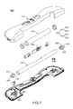
- FIG. 6 is a schematic side view illustrating a holder and a sleeve of a control device according to a fourth embodiment of the present invention.
- FIG. 8 is a schematic exploded view illustrating some components of the control device according to the fifth embodiment of the present invention.
- FIG. 9 is a schematic perspective view illustrating the outward appearance of a combination of a control device, a 3D wheel, a control pad and a control module according to a sixth embodiment of the present invention.
- FIG. 10 is a schematic perspective view illustrating the outward appearance of a combination of a feeding scanner and a control device according to a seventh embodiment of the present invention.
- FIG. 11 is a schematic perspective view illustrating the outward appearance of a combination of a control device and a handheld scanning device according to an eighth embodiment of the present invention.
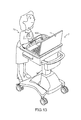
- FIG. 13 is a schematic perspective view illustrating another application environment of a control device according to a tenth embodiment of the present invention.
- the present invention provides a control device.
- a control member may be accommodated within the control device of the present invention.
- the control member is accommodated within an accommodation chamber of the control device and the portion thereof may be exposed for user's operation.
- the housing 110 is affixed on the bottom shell 160.
- An operating space is defined between the housing 110 and the bottom shell 160 for accommodating other modules (e.g. a circuit module or a control module, not shown) or a connecting interface 163, which will be described later.
- a hollow part 111, a notch 112 and a concave structure 113 are formed in the surface of the housing 110.
- the hollow part 111 is in communication with the operating space.
- the plaque 102 is accommodated within the hollow part 111.
- the wrist rest 101 is accommodated within the concave structure 113.
- the plaque 102 may be replaced by a touchpad (not shown) or a roller for the operation of the user.
- two receiving recesses 114 are located at bilateral sides of the notch 112, respectively.
- the receiving recess 114 is used for accommodating a corresponding holder 130.
- the sleeve 120 is exposed to the notch 112.
- the holder 130 comprises an one-piece fixing part or an assembled fixing part.
- the one-piece fixing part 134 is a cylindrical bar or an elliptic cylindrical bar.
- the one-piece fixing part 134 may have any shape for facilitating the sheathing, rotating and translational movement of the sleeve 120.
- the one-piece fixing part 134 is made of polyoxymetylene (POM), polytetrafluoroethylene (PTFE), ultra high molecular weight polyethylene (UHMWPE) or any of a variety of other suitable self-lubricating materials.
- POM polyoxymetylene
- PTFE polytetrafluoroethylene
- UHMWPE ultra high molecular weight polyethylene
- An accommodation chamber 131 is defined within the holder 130 for accommodating the detecting module 140, which is supported on a supporting seat 133.
- the one-piece fixing part 134 of the holder 130 has a vacant zone 132, and the detecting module 140 is exposed to the vacant zone 132. That is, the vacant zone 132 is aligned with the detecting module 140.
- the vacant zone 132 of the holder 130 is sheltered by the sleeve 120 when the sleeve 120 is sleeved onto the holder 130 and moved on the holder 130 leftwards and rightwards.
- the vacant zone 132 is produced or formed in a surface of the one-piece fixing part 134 (i.e. a hollow bar).
- the vacant zone 132 may be covered by a transparent cover (not shown), or a light-transmissible zone made of a transparent material is produced or formed as a portion or the whole of the one-piece fixing part 134.
- a circuit module 170 is affixed on the supporting seat 133 of the holder 130 for supporting the detecting module 140.
- the circuit module 170 further comprises a microprocessor 171.
- the rotating control signal or the moving control signal outputted from the detecting module 140 is transmitted to the microprocessor 171.
- the processed rotating control signal or the processed moving control signal is transmitted to the connecting interface 163 on the bottom shell 160, thereby controlling the movement of a cursor (not shown) on a display screen of an external electronic device.
- the clicking signal sensor 162 is a contact sensor.
- the holder 130 generates a first vertical displacement relative to the positioning part 151 in response to downward force imposed on the holder 130 by a user, and further compress the elastic element 161.
- the pressing part 155 In response to the first vertical displacement of the holder 130 synchronously, the pressing part 155 generates a second vertical displacement relative to the positioning part 151, so that the clicking signal sensor 162 is touched by the pressing part 155.
- a clicking control signal is generated.
- another circuit module 164 is disposed on the bottom shell 160. The clicking control signal outputted from the clicking signal sensor 162 is transmitted to the circuit module 164.
- the processed clicking control signal is transmitted to the connecting interface 163.
- the magnitude of the first vertical displacement is different from the magnitude of the second vertical displacement.
- the second vertical displacement may be smaller than (but is not limited to be smaller than) the first vertical displacement.
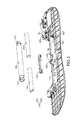
- FIG. 4 is a schematic exploded view illustrating a control device according to a third embodiment of the present invention.
- FIG. 5 is a schematic exploded view illustrating some components of the control device according to the third embodiment of the present invention.
- the control device 300 comprises a holder 330, a circuit module 370, another circuit module 364, a sleeve 320, a housing 310, and a bottom shell 360.
- an operating space 315 is defined between the bottom shell 360 and the housing 310.
- the operating space 315 can accommodate most components (e.g. the holder 330, the circuit module 364, the sleeve 320, and a plurality of control members 365) of the control device 300.
- a hollow part 311 and a slot 312 are formed in the housing 310.
- the control members 365 are disposed under the hollow part 311 and exposed to the hollow part 311.
- the sleeve 320 is sleeved onto the holder 330 and exposed to the slot 312.
- a wrist rest 301 and a plaque 302 are disposed on the housing 310.
- the wrist rest 301 is made of a soft material or an elastic material.
- the wrist rest 301 is a device used to support the wrist.
- the plaque 302 also has a plurality of apertures at the position corresponding to the hollow part 311 to expose the underlying control members 365.
- the circuit module 364 comprises a circuit board 366, which is affixed on the bottom shell 360.
- a plurality of control switches 367 and the control members 365 are mounted on the circuit board 366.
- some of the control switches 367 are aligned with corresponding control members 365 that are disposed over the control switches 367.
- the control member 365 may include a key, a wheel, a 3D wheel or any other operable element by a user's hand.
- the function of controlling a mouse cursor is achievable by simply pressing or rotating the control member 365 to trigger a corresponding control switch 367 of the circuit module 364.
- the example of the control member 365 is presented herein for purpose of illustration and description only. It is noted that numerous modifications and alterations may be made while retaining the teachings of the invention.
- the circuit module 364 further comprises a connecting interface 363, which is located at one side of the circuit board 366.
- a hollow recess (not shown) is formed at a lateral edge of the housing 310, and the connecting interface 363 is penetrated through the hollow recess.
- the circuit module 364 comprises a circuit board 366.
- the circuit module 364 may comprise a plurality of individual circuit boards rather than a single circuit board.
- Other circuit modules which will be described as follows may be integrated into the above circuit module or may be independent circuit modules. For designing the independent circuit modules, the independent circuit modules may be in communication with each other or an external electronic device through wires (or transmission lines) and the connecting interface, or the independent circuit modules may separately transmit and receive signals.
- the positioning part 351 After the positioning part 351 is penetrated through a pivotal hole 358 of the corresponding pushing seat 357 and an elastic element (not shown), the positioning part 351 is inserted into a pivotal hole 359 of the corresponding transmission member 353.
- the positioning part 351 is directly affixed on the bottom shell 360 through a supporting part 356 of the positioning mechanism 350.
- the positioning part 351 is affixed on the bottom shell 360 through any other supporting part (not shown).
- An example of the supporting part includes but is not limited to a positioning shaft.
- the pushing seat 357 is movable on the positioning part 351. In a case that an external force is exerted on the pushing seat 357 along a longitudinal direction of the positioning part 351, the pushing seat 357 is moved toward the transmission member 353 to compress the elastic element on the positioning part 351. Moreover, due to the elastic potential energy of the compressed elastic element, the pushing seat 357 is returned to the original position where no external force is exerted on the pushing seat 357.
- a magnet (not shown) may be disposed within the pushing seat 357.
- a magnetic sensor 369 is mounted on the circuit board 366 and located near the pushing seat 357.
- the magnetic sensor 369 is a Hall lC sensor or a magnetoresistive sensor (MR sensor).
- the magnetic field of the magnet applied to the magnetic sensor 369 is changed. Under this circumstance, the variance of the magnetic field is detected by the magnetic sensor 369. When the variance of the magnetic field or the magnitude of the magnetic field reaches a predetermined value, the magnetic sensor 369 generates a reset control signal to the circuit module 364. The reset control signal is further outputted from the connecting interface 363 to control a cursor reset of the external electronic device.
- the transmission member 353 further comprises a pressing part 355 and a sheathing part 354.
- the pressing part 355 and the sheathing part 354 are located at the position corresponding to the holder 330.
- the sheathing part 354 is connected with the fixing part 334 of the holder 330, so that the holder 330 is sustained against the transmission member 353 to be in the suspending state.
- a control switch 361 is disposed under the pressing part 355.
- the control switch 361 is in contact with the pressing part 355, so that the holder 330 in a suspending state is floated over the bottom shell 360.
- the transmission member 353 is rotatable relative to the positioning part 351.
- the holder 330 When a downward force is exerted on the holder 330, the holder 330 generates a first vertical displacement relative to the positioning part 351, so that the transmission member 353 is driven to rotate.
- the pressing part 355 In response to the first vertical displacement of the holder 330, the pressing part 355 generates a second vertical displacement relative to the positioning part 351, so that the control switch 361 is pressed by the pressing part 355.
- a triggering signal is generated.
- the magnitude of the first vertical displacement is substantially equal to the magnitude of the second vertical displacement.
- the sleeve 320 has an axial hole to be sleeved onto the supporting seat 333 of the holder 330.
- the length of the sleeve 320 along the longitudinal axis is shorter than the length of the supporting seat 333, so that the sleeve 320 is movable or rotatable on the supporting seat 333.
- the supporting seat 333 of the holder 330 may has a flat, arc-shaped, circular or elliptical cross section.
- the supporting seat 333 may have any shape for facilitating the sheathing, rotating and translational movement of the sleeve 320.
- the supporting seat 333 is made of polyoxymetylene (POM), polytetrafluoroethylene (PTFE), ultra high molecular weight polyethylene (UHMWPE) or any of a variety of other suitable self-lubricating materials.
- the supporting seat 333 of the holder 330 may be made of any other suitable material such as a steel material or a plastic material with few parting lines or no parting lines as long as the sleeve 320 can be rotated or moved on the supporting seat 333.
- the holder 330 has a light-transmission zone, which is sheathed by the sleeve 320, or a vacant zone 332.
- the sleeve 320 may be made of a suitable material in order to provide desired elasticity and flexibility.
- the sleeve 320 is made of mesh fabric, nonwoven fabric, plastic material, rubber or leather.
- several friction structures 322 are formed on the outer surface of the sleeve 320 for providing a friction force for facilitating the user to rotate or move the sleeve 320.
- the friction structures 322 are a plurality of convex structures having a coefficient of friction higher than the sleeve 320 and disposed on the outer surface of the sleeve 320 along the longitudinal axis of the sleeve 320 (or slightly tilted relative to the longitudinal axis of the sleeve 320).
- FIG. 6 is a schematic side view illustrating a holder and a sleeve of a control device according to a fourth embodiment of the present invention.
- a plurality of detecting modules 440 are accommodated within the accommodation chamber of the holder 430.
- a plurality of sensing structures 423 are distributed on the inner surface of the sleeve 420. After the sensing structures 423 are formed on the inner surface of the sleeve 420, the translational movement and the rotation of the sleeve 420 on the holder 430 are not blocked by the sensing structures 423.
- FIG. 10 is a schematic perspective view illustrating the outward appearance of a combination of a feeding scanner and a control device according to a seventh embodiment of the present invention.
- the feeding scanner 885 is disposed under the control device 800.
- the paper sheets are directly fed into the feeding scanner 885. Since the scanning module is integrated into the control device 800, the functions of the control device 800 are expanded.
- control device of the present invention is suitably applied to a platform environment with a limited space.
- the control device of the present invention is easily operated by the standing user in order to enhance the flexibility of operating the electronic device.
Landscapes
- Engineering & Computer Science (AREA)
- General Engineering & Computer Science (AREA)
- Theoretical Computer Science (AREA)
- Human Computer Interaction (AREA)
- Physics & Mathematics (AREA)
- General Physics & Mathematics (AREA)
- Position Input By Displaying (AREA)
- Switches With Compound Operations (AREA)
- Automatic Assembly (AREA)
- Accommodation For Nursing Or Treatment Tables (AREA)
Applications Claiming Priority (1)
| Application Number | Priority Date | Filing Date | Title |
|---|---|---|---|
| TW099225383U TWM407435U (en) | 2010-12-29 | 2010-12-29 | Manipulation control device |
Publications (2)
| Publication Number | Publication Date |
|---|---|
| EP2472360A2 true EP2472360A2 (fr) | 2012-07-04 |
| EP2472360A3 EP2472360A3 (fr) | 2014-10-01 |
Family
ID=45081210
Family Applications (2)
| Application Number | Title | Priority Date | Filing Date |
|---|---|---|---|
| EP11165873A Withdrawn EP2472359A2 (fr) | 2010-12-29 | 2011-05-12 | Dispositif de contrôle de l'exploitation |
| EP11195920.1A Withdrawn EP2472360A3 (fr) | 2010-12-29 | 2011-12-28 | Dispositif de commande |
Family Applications Before (1)
| Application Number | Title | Priority Date | Filing Date |
|---|---|---|---|
| EP11165873A Withdrawn EP2472359A2 (fr) | 2010-12-29 | 2011-05-12 | Dispositif de contrôle de l'exploitation |
Country Status (5)
| Country | Link |
|---|---|
| US (1) | US8314771B2 (fr) |
| EP (2) | EP2472359A2 (fr) |
| JP (1) | JP3174253U (fr) |
| CA (1) | CA2762803A1 (fr) |
| TW (1) | TWM407435U (fr) |
Families Citing this family (6)
| Publication number | Priority date | Publication date | Assignee | Title |
|---|---|---|---|---|
| US9024873B2 (en) * | 2010-05-04 | 2015-05-05 | Chen-Min Hung | Control device |
| TWM422108U (en) * | 2011-08-01 | 2012-02-01 | Ergzon Co Ltd | Control device |
| SE536633C2 (sv) * | 2012-11-02 | 2014-04-15 | Gunnar Drougge | Koordinatanordning med nedtryckningsfunktion |
| WO2014186806A1 (fr) * | 2013-05-17 | 2014-11-20 | SeeScan, Inc. | Dispositifs d'interface utilisateur |
| US10379637B2 (en) * | 2015-01-30 | 2019-08-13 | Logitech Europe S.A. | Rotational element enabling touch-like gestures |
| CN104883531A (zh) * | 2015-05-14 | 2015-09-02 | 无锡华海天和信息科技有限公司 | 一种视频通话中回音消除的实现方法 |
Family Cites Families (11)
| Publication number | Priority date | Publication date | Assignee | Title |
|---|---|---|---|---|
| US6211860B1 (en) * | 1994-07-06 | 2001-04-03 | Hewlett-Packard Company | Pressure sensitive electronic device |
| US6034670A (en) * | 1996-09-30 | 2000-03-07 | Chen; Mei Yun | Cursor positioning apparatus |
| JP2000132331A (ja) * | 1998-08-21 | 2000-05-12 | Shinsuke Hamaji | ロ―ラ―スライド式ポインティングデバイス |
| US6809724B1 (en) * | 2000-01-18 | 2004-10-26 | Seiko Epson Corporation | Display apparatus and portable information processing apparatus |
| US7770118B2 (en) * | 2006-02-13 | 2010-08-03 | Research In Motion Limited | Navigation tool with audible feedback on a handheld communication device having a full alphabetic keyboard |
| US7903087B2 (en) * | 2006-02-13 | 2011-03-08 | Research In Motion Limited | Method for facilitating navigation and selection functionalities of a trackball incorporated upon a wireless handheld communication device |
| JP4767200B2 (ja) * | 2007-03-08 | 2011-09-07 | 任天堂株式会社 | 情報選択装置および情報選択プログラム |
| US8866743B2 (en) * | 2007-07-16 | 2014-10-21 | Blackberry Limited | Navigational tool with drag-based tactile feedback on a handheld wireless communication device |
| TWM363635U (en) * | 2009-03-04 | 2009-08-21 | Chance Steel Mold Co Ltd | Manipulation control device |
| EP2228110B1 (fr) * | 2009-03-09 | 2017-08-30 | Nintendo Co., Ltd. | Appareil de calcul des coordonnées et support de stockage comportant un programme de calcul des coordonnées |
| US8441438B2 (en) * | 2010-01-06 | 2013-05-14 | Cywee Group Limited | 3D pointing device and method for compensating movement thereof |
-
2010
- 2010-12-29 TW TW099225383U patent/TWM407435U/zh not_active IP Right Cessation
-
2011
- 2011-04-20 US US13/064,828 patent/US8314771B2/en not_active Expired - Fee Related
- 2011-05-12 EP EP11165873A patent/EP2472359A2/fr not_active Withdrawn
- 2011-12-28 EP EP11195920.1A patent/EP2472360A3/fr not_active Withdrawn
- 2011-12-28 CA CA2762803A patent/CA2762803A1/fr not_active Abandoned
- 2011-12-28 JP JP2011007765U patent/JP3174253U/ja not_active Expired - Fee Related
Non-Patent Citations (1)
| Title |
|---|
| None |
Also Published As
| Publication number | Publication date |
|---|---|
| CA2762803A1 (fr) | 2012-06-29 |
| EP2472360A3 (fr) | 2014-10-01 |
| JP3174253U (ja) | 2012-03-08 |
| EP2472359A2 (fr) | 2012-07-04 |
| TWM407435U (en) | 2011-07-11 |
| US8314771B2 (en) | 2012-11-20 |
| US20120169595A1 (en) | 2012-07-05 |
Similar Documents
| Publication | Publication Date | Title |
|---|---|---|
| US9024873B2 (en) | Control device | |
| US9128539B2 (en) | Ergonomic mouse device with multi-programmable buttons | |
| EP2472360A2 (fr) | Dispositif de commande | |
| US10379635B2 (en) | Pointing device | |
| EP0571068A1 (fr) | Dispositif de pointage pour ordinateur portable | |
| US9240299B2 (en) | Pivotable key structure | |
| US8830166B2 (en) | Sleeve and control device with such sleeve | |
| US20070139377A1 (en) | Cursor control device | |
| JP2006004453A (ja) | タッチ操作型コンピュータ | |
| US20110037693A1 (en) | Cursor control device | |
| CA2752015A1 (fr) | Dispositif de commande | |
| US7808482B2 (en) | Slim mouse | |
| CN107077232B (zh) | 指向装置托架组合件及系统 | |
| US20070036603A1 (en) | Portable keyboard | |
| US20120162071A1 (en) | Control device | |
| US20130120264A1 (en) | Control device | |
| EP2605110A2 (fr) | Dispositif de commande | |
| EP2431843A2 (fr) | Dispositif de commande | |
| WO2013091332A1 (fr) | Dispositif d'actionnement et de commande | |
| US20120062458A1 (en) | Control device |
Legal Events
| Date | Code | Title | Description |
|---|---|---|---|
| AK | Designated contracting states |
Kind code of ref document: A2 Designated state(s): AL AT BE BG CH CY CZ DE DK EE ES FI FR GB GR HR HU IE IS IT LI LT LU LV MC MK MT NL NO PL PT RO RS SE SI SK SM TR |
|
| AX | Request for extension of the european patent |
Extension state: BA ME |
|
| PUAI | Public reference made under article 153(3) epc to a published international application that has entered the european phase |
Free format text: ORIGINAL CODE: 0009012 |
|
| RAP1 | Party data changed (applicant data changed or rights of an application transferred) |
Owner name: HUNG, CHEN-MIN |
|
| PUAL | Search report despatched |
Free format text: ORIGINAL CODE: 0009013 |
|
| AK | Designated contracting states |
Kind code of ref document: A3 Designated state(s): AL AT BE BG CH CY CZ DE DK EE ES FI FR GB GR HR HU IE IS IT LI LT LU LV MC MK MT NL NO PL PT RO RS SE SI SK SM TR |
|
| AX | Request for extension of the european patent |
Extension state: BA ME |
|
| RIC1 | Information provided on ipc code assigned before grant |
Ipc: G06F 3/0354 20130101AFI20140826BHEP Ipc: G06F 3/0362 20130101ALI20140826BHEP Ipc: H01H 25/00 20060101ALI20140826BHEP |
|
| STAA | Information on the status of an ep patent application or granted ep patent |
Free format text: STATUS: THE APPLICATION IS DEEMED TO BE WITHDRAWN |
|
| 18D | Application deemed to be withdrawn |
Effective date: 20150402 |