EP2472084A2 - Method and system for powering a vehicle - Google Patents
Method and system for powering a vehicle Download PDFInfo
- Publication number
- EP2472084A2 EP2472084A2 EP11194243A EP11194243A EP2472084A2 EP 2472084 A2 EP2472084 A2 EP 2472084A2 EP 11194243 A EP11194243 A EP 11194243A EP 11194243 A EP11194243 A EP 11194243A EP 2472084 A2 EP2472084 A2 EP 2472084A2
- Authority
- EP
- European Patent Office
- Prior art keywords
- electrical
- generator
- shaft
- bus
- accordance
- Prior art date
- Legal status (The legal status is an assumption and is not a legal conclusion. Google has not performed a legal analysis and makes no representation as to the accuracy of the status listed.)
- Granted
Links
Images

Classifications
-
- F—MECHANICAL ENGINEERING; LIGHTING; HEATING; WEAPONS; BLASTING
- F02—COMBUSTION ENGINES; HOT-GAS OR COMBUSTION-PRODUCT ENGINE PLANTS
- F02C—GAS-TURBINE PLANTS; AIR INTAKES FOR JET-PROPULSION PLANTS; CONTROLLING FUEL SUPPLY IN AIR-BREATHING JET-PROPULSION PLANTS
- F02C7/00—Features, components parts, details or accessories, not provided for in, or of interest apart form groups F02C1/00 - F02C6/00; Air intakes for jet-propulsion plants
- F02C7/32—Arrangement, mounting, or driving, of auxiliaries
-
- F—MECHANICAL ENGINEERING; LIGHTING; HEATING; WEAPONS; BLASTING
- F02—COMBUSTION ENGINES; HOT-GAS OR COMBUSTION-PRODUCT ENGINE PLANTS
- F02C—GAS-TURBINE PLANTS; AIR INTAKES FOR JET-PROPULSION PLANTS; CONTROLLING FUEL SUPPLY IN AIR-BREATHING JET-PROPULSION PLANTS
- F02C7/00—Features, components parts, details or accessories, not provided for in, or of interest apart form groups F02C1/00 - F02C6/00; Air intakes for jet-propulsion plants
- F02C7/36—Power transmission arrangements between the different shafts of the gas turbine plant, or between the gas-turbine plant and the power user
-
- F—MECHANICAL ENGINEERING; LIGHTING; HEATING; WEAPONS; BLASTING
- F05—INDEXING SCHEMES RELATING TO ENGINES OR PUMPS IN VARIOUS SUBCLASSES OF CLASSES F01-F04
- F05D—INDEXING SCHEME FOR ASPECTS RELATING TO NON-POSITIVE-DISPLACEMENT MACHINES OR ENGINES, GAS-TURBINES OR JET-PROPULSION PLANTS
- F05D2220/00—Application
- F05D2220/70—Application in combination with
- F05D2220/76—Application in combination with an electrical generator
-
- F—MECHANICAL ENGINEERING; LIGHTING; HEATING; WEAPONS; BLASTING
- F05—INDEXING SCHEMES RELATING TO ENGINES OR PUMPS IN VARIOUS SUBCLASSES OF CLASSES F01-F04
- F05D—INDEXING SCHEME FOR ASPECTS RELATING TO NON-POSITIVE-DISPLACEMENT MACHINES OR ENGINES, GAS-TURBINES OR JET-PROPULSION PLANTS
- F05D2240/00—Components
- F05D2240/40—Use of a multiplicity of similar components
-
- F—MECHANICAL ENGINEERING; LIGHTING; HEATING; WEAPONS; BLASTING
- F05—INDEXING SCHEMES RELATING TO ENGINES OR PUMPS IN VARIOUS SUBCLASSES OF CLASSES F01-F04
- F05D—INDEXING SCHEME FOR ASPECTS RELATING TO NON-POSITIVE-DISPLACEMENT MACHINES OR ENGINES, GAS-TURBINES OR JET-PROPULSION PLANTS
- F05D2260/00—Function
- F05D2260/85—Starting
-
- F—MECHANICAL ENGINEERING; LIGHTING; HEATING; WEAPONS; BLASTING
- F05—INDEXING SCHEMES RELATING TO ENGINES OR PUMPS IN VARIOUS SUBCLASSES OF CLASSES F01-F04
- F05D—INDEXING SCHEME FOR ASPECTS RELATING TO NON-POSITIVE-DISPLACEMENT MACHINES OR ENGINES, GAS-TURBINES OR JET-PROPULSION PLANTS
- F05D2270/00—Control
- F05D2270/01—Purpose of the control system
- F05D2270/10—Purpose of the control system to cope with, or avoid, compressor flow instabilities
- F05D2270/101—Compressor surge or stall
-
- Y—GENERAL TAGGING OF NEW TECHNOLOGICAL DEVELOPMENTS; GENERAL TAGGING OF CROSS-SECTIONAL TECHNOLOGIES SPANNING OVER SEVERAL SECTIONS OF THE IPC; TECHNICAL SUBJECTS COVERED BY FORMER USPC CROSS-REFERENCE ART COLLECTIONS [XRACs] AND DIGESTS
- Y02—TECHNOLOGIES OR APPLICATIONS FOR MITIGATION OR ADAPTATION AGAINST CLIMATE CHANGE
- Y02T—CLIMATE CHANGE MITIGATION TECHNOLOGIES RELATED TO TRANSPORTATION
- Y02T50/00—Aeronautics or air transport
- Y02T50/60—Efficient propulsion technologies, e.g. for aircraft
Definitions
- the field of the invention relates generally to aircraft electrical power generating and distribution systems and more specifically, to a method and system for reducing a potential for a high pressure turbine stall.
- the aircraft system also includes a VF bus electrically coupled to said VF electrical generator, said VF bus configured to supply power to a portion of the electrical loads of the aircraft system, and a CF bus electrically coupled to said CF electrical generator, said CF bus configured to supply power to a remaining portion of the electrical loads of the aircraft system.
Landscapes
- Engineering & Computer Science (AREA)
- Chemical & Material Sciences (AREA)
- Combustion & Propulsion (AREA)
- Mechanical Engineering (AREA)
- General Engineering & Computer Science (AREA)
- Control Of Eletrric Generators (AREA)
- Control Of Turbines (AREA)
- Connection Of Motors, Electrical Generators, Mechanical Devices, And The Like (AREA)
Abstract
Description
- The field of the invention relates generally to aircraft electrical power generating and distribution systems and more specifically, to a method and system for reducing a potential for a high pressure turbine stall.
- At least some known aircraft are driven by two or more high bypass ratio turbofan engines. These engines include a fan driven by a low pressure spool that provides a significant fraction of the overall propulsion system thrust. A high pressure spool drives one or more compressors, and produces additional thrust by directing exhaust products in an aft direction.
- In addition to providing thrust to propel the aircraft, and powering the aircraft hydraulic and pneumatic systems, the engines provide electrical power to many aircraft components, including the environmental control system, aircraft computers, hydraulic motor pumps, and/or other motors and electrical devices. One approach to obtaining electrical power from the aircraft engines is to convert some of the rotational mechanical power from the engine to electrical power.
- Newer aircraft have smaller engines with more limitations on the high pressure spool power extraction to avoid stalls. Also, the newer aircraft are designed with more electrical loads. Under certain conditions, such as, but not limited to, during the descend condition, sufficient power from the high pressure spool may not be available to support the electrical loads without stalling the compressor. Because the engine stall problem is a relatively new problem, there have been limited attempts to solve it.
- In one embodiment, a gas turbine engine system includes a low-pressure (LP) shaft, a high-pressure (HP) shaft, a constant speed mechanical drive assembly having an input and an output, the input mechanically coupled to the LP shaft, the output mechanically coupled to a constant frequency (CF) electrical generator, and an accessory gearbox assembly having an input and an output, the input mechanically coupled to the HP shaft, the output mechanically coupled to a variable frequency (VF) electrical generator.
- In another embodiment, a method for operating an aircraft system includes starting a turbofan engine by driving a first shaft with a starter/generator, the first shaft being connected between a compressor and a first turbine of the engine, supplying variable frequency (VF) electrical energy to a VF electrical bus using the starter/generator, supplying constant frequency (CF) electrical energy to a CF electrical bus using a generator coupled to a second shaft connected between a fan and a second turbine of the engine, and distributing the variable frequency (VF) electrical energy to aircraft components from the VF electrical bus and the constant frequency (CF) electrical energy to other aircraft components from the CF electrical bus.
- In yet another embodiment, an aircraft system includes a gas turbine engine that includes: a compressor coupled to a first turbine through a high pressure (HP) shaft extending between the compressor and the first turbine, a variable frequency (VF) electrical generator, an accessory gearbox assembly having an input and an output, the input mechanically coupled to the HP shaft, the output mechanically coupled to the variable frequency (VF) electrical generator, a fan coupled to a second turbine through a low pressure (LP) shaft extending between the fan and the second turbine and co-axial with the high pressure shaft, a constant frequency (CF) electrical generator, a constant speed mechanical drive assembly having an input and an output, the input mechanically coupled to the LP shaft, and the output mechanically coupled to the constant frequency (CF) electrical generator. The aircraft system also includes a VF bus electrically coupled to said VF electrical generator, said VF bus configured to supply power to a portion of the electrical loads of the aircraft system, and a CF bus electrically coupled to said CF electrical generator, said CF bus configured to supply power to a remaining portion of the electrical loads of the aircraft system.
-
-
Figures 1 and2 show exemplary embodiments of the method and system described herein. -
Figure 1 is a schematic cross-sectional diagram of an aircraft gas turbine engine in accordance with an exemplary embodiment of the present invention; and -
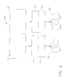
Figure 2 is a schematic block diagram of an electrical system architecture in accordance with an exemplary embodiment of the present invention. - The following detailed description illustrates embodiments of the invention by way of example and not by way of limitation. The description clearly enables one skilled in the art to make and use the disclosure, describes several embodiments, adaptations, variations, alternatives, and uses of the disclosure, including what is presently believed to be the best mode of carrying out the disclosure. The disclosure is described as applied to an exemplary embodiment, namely, systems and methods of powering an aircraft. However, it is contemplated that this disclosure has general application to electrical system architectures in industrial, commercial, and residential applications.
- As used herein, an element or step recited in the singular and preceded with the word "a" or "an" should be understood as not excluding plural elements or steps, unless such exclusion is explicitly recited. Furthermore, references to "one embodiment" of the present invention are not intended to be interpreted as excluding the existence of additional embodiments that also incorporate the recited features.
- Embodiments of the present invention provide a new electrical system architecture for aircraft that includes Constant Frequency (CF) AC power obtained from the Low Pressure (LP) spool of turbine engine through a gearbox-Constant Speed Mechanical Drive-Constant Frequency (CF) AC generator, and the Variable Frequency (VF) AC power obtained through the High Pressure (HP) spool of turbine engine driving the accessory gearbox VF Generator. Electrical loads requiring CF power are supplied by the LP spool driven CF generator while the electrical loads which can tolerate VF power are supplied through the HP spool driven VF generator. This architecture, therefore does not require any power electronics based conversion equipment and solves the potential turbine operability/stall issue by maximizing the extracted power through the LP spool of the turbine and minimizing the power extraction from the HP spool of the turbine under the descend mode of the aircraft where the engine stall margin is reduced. Moreover, the HP spool driven generator can also be configured to be a Starter-Generator, for starting the turbine engine.
-
Figure 1 is a schematic cross-sectional diagram of an exemplary embodiment of an aircraftgas turbine engine 10 having anengine axis 8, such as a GE CFM56 series engine.Engine 10 includes, in downstream serial flow relationship, afan section 13 including afan 14, a booster or low pressure compressor (LPC) 16, a high pressure compressor (HPC) 18, acombustion section 20, a high pressure turbine (HPT) 22, and a low pressure turbine (LPT) 24. Ahigh pressure shaft 26 drivingly connects HPT 22 to HPC 18 and alow pressure shaft 28 drivingly connectsLPT 24 toLPC 16 andfan 14. HPT 22 includes anHPT rotor 30 havingturbine blades 34 mounted at a periphery ofrotor 30.Blades 34 extend radially outwardly from blade platforms 39 to radially outer blade tips. -
Figure 2 is a schematic block diagram of anelectrical system architecture 200 in accordance with an exemplary embodiment of the present invention. In the exemplary embodiment,electrical system architecture 200 includes a variable frequencyelectrical bus 202 configured to supply electrical power to a plurality ofloads 204 that can tolerate a supply having a variable frequency during operation.Electrical system architecture 200 also includes a constant frequencyelectrical bus 206 configured to supply electrical power to a plurality ofloads 208 that use electrical power having a constant frequency during operation. Constant frequencyelectrical bus 206 is also configured to supply electrical power to one ormore loads 210 that can tolerate a supply having a variable frequency during operation. - Electrical power is supplied to variable frequency
electrical bus 202 from a variable frequencyelectrical generator 212. In various embodiments, variable frequencyelectrical generator 212 comprises a starter/generator configured to supply a rotational torque tohigh pressure shaft 26 during a starting process. Electrical power is supplied to constant frequencyelectrical bus 206 from a constant frequencyelectrical generator 214. Variable frequencyelectrical generator 212 is driven byhigh pressure shaft 26 through anaccessory gearbox 216 mechanically coupled betweenhigh pressure shaft 26 and variable frequencyelectrical generator 212. Constant frequencyelectrical generator 214 is driven bylow pressure shaft 28 through a constant speedmechanical drive assembly 218 mechanically coupled betweenlow pressure shaft 28 and constant frequencyelectrical generator 214. - In the exemplary embodiment, no further conditioning of the VF and CF power is required, for example, the VF and CF power are used on an as is basis without the need for power conversion equipment. Loads requiring CF power for their proper operation are fed from the
low pressure shaft 28 driven constant frequencyelectrical generator 214 whereas the remainder of the loads are powered by variable frequencyelectrical generator 212. - By maintaining a certain minimum loading on
low pressure shaft 28 driven constant frequencyelectrical generator 214 and minimizing the power extraction from thehigh pressure shaft 26 driven variable frequencyelectrical generator 212, a potential stall of the turbine during a descend mode of the aircraft when the engine is operating at or near idle speed to minimize thrust. - Technical advantages of embodiments of the present invention include avoiding use of power conversion equipment is avoided for
high pressure shaft 26 driven variable frequencyelectrical generator 212 because CF power needed for certain loads is obtained from thelow pressure shaft 28 driven constant frequencyelectrical generator 214 and eliminating potential turbine stall under certain operating conditions, for example, during aircraft descend mode by shifting loading fromhigh pressure shaft 26 tolow pressure shaft 28. Embodiments of the present invention also provide a lower cost electrical system architecture having a higher efficiency. - The above-described embodiments of a method and system of obtaining aircraft CF power the LP Spool of the turbine by a drive/constant speed generator while VF power is obtained from an HP spool driven generator provides a cost-effective and reliable means for eliminating power conversion equipment for CF power and eliminating stalling of the HP spool by extracting the power from the LP spool. As a result, the method and system described herein facilitate aircraft operations in a cost-effective and reliable manner.
- This written description uses examples to disclose the invention, including the best mode, and also to enable any person skilled in the art to practice the invention, including making and using any devices or systems and performing any incorporated methods. The patentable scope of the invention is defined by the claims, and may include other examples that occur to those skilled in the art. Such other examples are intended to be within the scope of the claims if they have structural elements that do not differ from the literal language of the claims, or if they include equivalent structural elements with insubstantial differences from the literal languages of the claims.
- Various aspects and embodiment of the invention are indicated by the following clauses:
- 1. A gas turbine engine system comprising:
- a low-pressure (LP) shaft;
- a high-pressure (HP) shaft;
- a constant speed mechanical drive assembly having an input and an output, the input mechanically coupled to the LP shaft, the output mechanically coupled to a constant frequency (CF) electrical generator; and
- an accessory gearbox assembly having an input and an output, the input mechanically coupled to the HP shaft, the output mechanically coupled to a variable frequency (VF) electrical generator.
- 2. A gas turbine engine system in accordance with Clause 1, wherein said CF electrical generator is electrically coupled to CF electrical bus.
- 3. A gas turbine engine system in accordance with Clause 1, wherein said VF electrical generator is electrically coupled to said VF electrical bus.
- 4. A gas turbine engine system in accordance with Clause 1, wherein said VF electrical generator comprises a starter/generator configured to turn said HP shaft during an engine startup process and to generate electrical power from the HP shaft during operation after startup.
- 5. A gas turbine engine system in accordance with Clause 1, wherein CF electrical power is supplied to the CF electrical bus directly from said CF generator.
- 6. A gas turbine engine system in accordance with Clause 1, wherein said CF electrical bus and said VF electrical bus are maintained electrically isolated.
- 7. A gas turbine engine system in accordance with Clause 1, wherein a rotational speed of said input of said constant speed mechanical drive assembly varies with a rotational speed of said LP shaft and a rotational speed of said output of said constant speed mechanical drive assembly is substantially constant.
- 8. A method for operating an aircraft system, said method comprising:
- starting a turbofan engine by driving a first shaft with a starter/generator, the first shaft being connected between a compressor and a first turbine of the engine;
- supplying variable frequency (VF) electrical energy to a VF electrical bus using the starter/generator;
- supplying constant frequency (CF) electrical energy to a CF electrical bus using a generator coupled to a second shaft connected between a fan and a second turbine of the engine; and
- distributing the variable frequency (VF) electrical energy to aircraft components from the VF electrical bus and the constant frequency (CF) electrical energy to other aircraft components from the CF electrical bus.
- 9. A method in accordance with
Clause 8, further comprising supplying VF electrical energy to the starter/generator from the VF electrical bus during starting. - 10. A method in accordance with
Clause 8, further comprising coupling an accessory gearbox assembly between the first shaft and the starter/generator. - 11. A method in accordance with
Clause 8, further comprising coupling a constant speed mechanical drive assembly between the second shaft and the generator. - 12. A method in accordance with
Clause 8, further comprising:- electrically uncoupling at least one load from the VF electrical bus; and
- electrically coupling the at least one load to the CF electrical bus such that a stall of the first turbine is facilitated being reduced.
- 13. A method in accordance with
Clause 8, wherein distributing the variable frequency (VF) electrical energy to aircraft components from the VF electrical bus and the constant frequency (CF) electrical energy to other aircraft components from the CF electrical bus further comprises maintaining the VF electrical bus and the CF electrical bus electrically isolated. - 14. A method in accordance with
Clause 8, wherein supplying variable frequency (VF) electrical energy to a VF electrical bus using the starter/generator comprises supplying variable frequency (VF) electrical energy to a VF electrical bus without using an electronic power converter. - 15. A method in accordance with
Clause 8, wherein supplying constant frequency (CF) electrical energy to a CF electrical bus comprises supplying constant frequency (CF) electrical energy to a CF electrical bus without using an electronic power converter - 16. An aircraft system, comprising:
- a gas turbine engine that includes:
- a compressor coupled to a first turbine through a high pressure (HP) shaft extending between the compressor and the first turbine;
- a variable frequency (VF) electrical generator;
- an accessory gearbox assembly having an input and an output, the input mechanically coupled to the HP shaft, the output mechanically coupled to the variable frequency (VF) electrical generator;
- a fan coupled to a second turbine through a low pressure (LP) shaft extending between the fan and the second turbine and co-axial with the high pressure shaft;
- a constant frequency (CF) electrical generator; and
- a constant speed mechanical drive assembly having an input and an output, the input mechanically coupled to the LP shaft, the output mechanically coupled to the constant frequency (CF) electrical generator;
- a VF bus electrically coupled to said VF electrical generator, said VF bus configured to supply power to a portion of the electrical loads of the aircraft system; and
- a CF bus electrically coupled to said CF electrical generator, said CF bus configured to supply power to a remaining portion of the electrical loads of the aircraft system.
- a gas turbine engine that includes:
- 17. An aircraft system in accordance with
Clause 16, wherein said VF generator further comprises a VF starter/generator, said VF electrical bus configured to supply VF electrical power to said VF starter/generator during a startup process of the gas turbine engine, said VF starter/generator configured to supply power to said VF electrical bus after the gas turbine engine has started up. - 18. An aircraft system in accordance with
Clause 16, wherein CF electrical power is supplied to the CF electrical bus directly from said CF generator. - 19. An aircraft system in accordance with
Clause 16, wherein said CF electrical bus and said VF electrical bus are maintained electrically isolated with respect to each other. - 20. An aircraft system in accordance with
Clause 16, wherein a rotational speed of said input of said constant speed mechanical drive assembly varies with a rotational speed of said LP shaft and a rotational speed of said output of said constant speed mechanical drive assembly is substantially constant.
Claims (15)
- A gas turbine engine system comprising:a low-pressure (LP) shaft;a high-pressure (HP) shaft;a constant speed mechanical drive assembly having an input and an output, the input mechanically coupled to the LP shaft, the output mechanically coupled to a constant frequency (CF) electrical generator; andan accessory gearbox assembly having an input and an output, the input mechanically coupled to the HP shaft, the output mechanically coupled to a variable frequency (VF) electrical generator.
- A gas turbine engine system in accordance with Claim 1, wherein said CF electrical generator is electrically coupled to a CF electrical bus.
- A gas turbine engine system in accordance with either of Claim 1 or 2, wherein said VF electrical generator is electrically coupled to a VF electrical bus.
- A gas turbine engine system in accordance with any preceding Claim, wherein said VF electrical generator comprises a starter/generator configured to turn said HP shaft during an engine startup process and to generate electrical power from the HP shaft during operation after startup.
- A gas turbine engine system in accordance with Claim 2, wherein CF electrical power is supplied to the CF electrical bus directly from said CF generator.
- A gas turbine engine system in accordance with Claim 3 when dependent upon Claim 2, wherein said CF electrical bus and said VF electrical bus are maintained electrically isolated.
- A gas turbine engine system in accordance with any preceding Claim, wherein a rotational speed of said input of said constant speed mechanical drive assembly varies with a rotational speed of said LP shaft and a rotational speed of said output of said constant speed mechanical drive assembly is substantially constant.
- A method for operating an aircraft system, said method comprising:starting a turbofan engine by driving a first shaft with a starter/generator, the first shaft being connected between a compressor and a first turbine of the engine;supplying variable frequency (VF) electrical energy to a VF electrical bus using the starter/generator;supplying constant frequency (CF) electrical energy to a CF electrical bus using a generator coupled to a second shaft connected between a fan and a second turbine of the engine; anddistributing the variable frequency (VF) electrical energy to aircraft components from the VF electrical bus and the constant frequency (CF) electrical energy to other aircraft components from the CF electrical bus.
- A method in accordance with Claim 8, further comprising supplying VF electrical energy to the starter/generator from the VF electrical bus during starting.
- A method in accordance with either of Claim 8 or 9, further comprising coupling an accessory gearbox assembly between the first shaft and the starter/generator.
- A method in accordance with any of Claims 8 to 10, further comprising coupling a constant speed mechanical drive assembly between the second shaft and the generator.
- A method in accordance with any of Claims 8 to 11, further comprising:electrically uncoupling at least one load from the VF electrical bus; andelectrically coupling the at least one load to the CF electrical bus such that a stall of the first turbine is facilitated being reduced.
- A method in accordance with any of Claims 8 to 12, wherein distributing the variable frequency (VF) electrical energy to aircraft components from the VF electrical bus and the constant frequency (CF) electrical energy to other aircraft components from the CF electrical bus further comprises maintaining the VF electrical bus and the CF electrical bus electrically isolated.
- A method in accordance with any of Claims 8 to 13 wherein supplying variable frequency (VF) electrical energy to a VF electrical bus using the starter/generator comprises supplying variable frequency (VF) electrical energy to a VF electrical bus without using an electronic power converter.
- An aircraft system, comprising:a gas turbine engine that includes:a compressor coupled to a first turbine through a high pressure (HP) shaft extending between the compressor and the first turbine;a variable frequency (VF) electrical generator;an accessory gearbox assembly having an input and an output, the input mechanically coupled to the HP shaft, the output mechanically coupled to the variable frequency (VF) electrical generator;a fan coupled to a second turbine through a low pressure (LP) shaft extending between the fan and the second turbine and co-axial with the high pressure shaft;a constant frequency (CF) electrical generator; anda constant speed mechanical drive assembly having an input and an output, the input mechanically coupled to the LP shaft, the output mechanically coupled to the constant frequency (CF) electrical generator;a VF bus electrically coupled to said VF electrical generator, said VF bus configured to supply power to a portion of the electrical loads of the aircraft system; anda CF bus electrically coupled to said CF electrical generator, said CF bus configured to supply power to a remaining portion of the electrical loads of the aircraft system.
Applications Claiming Priority (1)
| Application Number | Priority Date | Filing Date | Title |
|---|---|---|---|
| US12/981,044 US8561413B2 (en) | 2010-12-29 | 2010-12-29 | System for powering a vehicle |
Publications (3)
| Publication Number | Publication Date |
|---|---|
| EP2472084A2 true EP2472084A2 (en) | 2012-07-04 |
| EP2472084A3 EP2472084A3 (en) | 2017-10-25 |
| EP2472084B1 EP2472084B1 (en) | 2020-05-20 |
Family
ID=45350706
Family Applications (1)
| Application Number | Title | Priority Date | Filing Date |
|---|---|---|---|
| EP11194243.9A Active EP2472084B1 (en) | 2010-12-29 | 2011-12-19 | Method and system for powering a vehicle |
Country Status (6)
| Country | Link |
|---|---|
| US (1) | US8561413B2 (en) |
| EP (1) | EP2472084B1 (en) |
| JP (1) | JP6001851B2 (en) |
| CN (1) | CN102562318B (en) |
| BR (1) | BRPI1105203B1 (en) |
| CA (1) | CA2762393C (en) |
Cited By (10)
| Publication number | Priority date | Publication date | Assignee | Title |
|---|---|---|---|---|
| FR2979498A1 (en) * | 2011-08-31 | 2013-03-01 | Hamilton Sundstrand Corp | MIXED MODE ENERGY GENERATION ARCHITECTURE |
| WO2014143218A1 (en) * | 2013-03-13 | 2014-09-18 | Rolls-Royce North American Technologies, Inc. | Gas turbine engine and electrical system comprising electrical buses |
| EP2657457A3 (en) * | 2012-04-27 | 2017-08-23 | IHI Aerospace Co., Ltd. | Electricity generation system |
| EP2636873A3 (en) * | 2012-03-07 | 2017-12-27 | GE Aviation Systems LLC | Apparatus for extracting input power from the low pressure spool of a turbine engine |
| EP3412575A1 (en) * | 2017-06-08 | 2018-12-12 | General Electric Company | Hybrid-electric propulsion system for an aircraft |
| EP3751114A1 (en) * | 2019-06-12 | 2020-12-16 | Rolls-Royce plc | Reducing low flight mach number fuel consumption in a gas turbine with electric machines |
| US11268454B2 (en) | 2019-06-12 | 2022-03-08 | Rolls-Royce Plc | Preventing surge |
| US11326526B2 (en) | 2019-06-12 | 2022-05-10 | Rolls-Royce Plc | Deceleration of a gas turbine |
| US11480112B2 (en) | 2019-06-12 | 2022-10-25 | Rolls-Royce Plc | Acceleration of a gas turbine |
| US11719117B2 (en) | 2019-06-12 | 2023-08-08 | Rolls-Royce Plc | Increasing surge margin and compression efficiency via shaft power transfer |
Families Citing this family (19)
| Publication number | Priority date | Publication date | Assignee | Title |
|---|---|---|---|---|
| US8723349B2 (en) * | 2011-10-07 | 2014-05-13 | General Electric Company | Apparatus for generating power from a turbine engine |
| EP2971699B8 (en) * | 2013-03-15 | 2020-01-15 | Rolls-Royce Corporation | Lifing and performance optimization limit management for turbine engine |
| FR3006669B1 (en) * | 2013-06-07 | 2015-06-05 | Eads Europ Aeronautic Defence | ELECTRIC POWER SUPPLY DEVICE FOR AN ELECTRIC PROPULSION AIRCRAFT |
| CN103867336B (en) * | 2014-04-07 | 2015-10-07 | 邱世军 | A kind of combination system taken into account jet propulsion and electric power and export |
| US10487839B2 (en) * | 2016-08-22 | 2019-11-26 | General Electric Company | Embedded electric machine |
| US10934935B2 (en) | 2017-01-30 | 2021-03-02 | Ge Aviation Systems Llc | Engine core assistance |
| US10793281B2 (en) | 2017-02-10 | 2020-10-06 | General Electric Company | Propulsion system for an aircraft |
| US11149578B2 (en) | 2017-02-10 | 2021-10-19 | General Electric Company | Propulsion system for an aircraft |
| US10822103B2 (en) | 2017-02-10 | 2020-11-03 | General Electric Company | Propulsor assembly for an aircraft |
| US11008111B2 (en) | 2017-06-26 | 2021-05-18 | General Electric Company | Propulsion system for an aircraft |
| CN107846124B (en) * | 2017-11-10 | 2019-11-05 | 猫头鹰安防科技有限公司 | A kind of disc type built-in type aviation start-generator |
| GB201804128D0 (en) * | 2018-03-15 | 2018-05-02 | Rolls Royce Plc | Electrical power generator system |
| US11097849B2 (en) | 2018-09-10 | 2021-08-24 | General Electric Company | Aircraft having an aft engine |
| CN110761849A (en) * | 2019-11-21 | 2020-02-07 | 中国航发贵阳发动机设计研究所 | Fan assembly with built-in generator |
| US11428171B2 (en) | 2019-12-06 | 2022-08-30 | General Electric Company | Electric machine assistance for multi-spool turbomachine operation and control |
| US11845388B2 (en) | 2021-05-20 | 2023-12-19 | General Electric Company | AC electrical power system for a vehicle |
| CN115234380B (en) * | 2022-08-02 | 2025-11-14 | 清华大学 | Engine control methods, devices, computer equipment and storage media |
| US12480449B2 (en) | 2022-08-22 | 2025-11-25 | General Electric Company | Propulsion system including an electric machine for starting a gas turbine engine |
| FR3143556B1 (en) * | 2022-12-16 | 2024-12-13 | Safran | Method for managing power transitions between a generation mode and an assistance mode |
Family Cites Families (10)
| Publication number | Priority date | Publication date | Assignee | Title |
|---|---|---|---|---|
| US7170262B2 (en) | 2003-12-24 | 2007-01-30 | Foundation Enterprises Ltd. | Variable frequency power system and method of use |
| US20070265761A1 (en) | 2006-05-11 | 2007-11-15 | Dooley Kevin A | Electric power generation system and method |
| US7750521B2 (en) * | 2006-12-07 | 2010-07-06 | General Electric Company | Double-sided starter/generator for aircrafts |
| US7622817B2 (en) * | 2006-12-13 | 2009-11-24 | General Electric Company | High-speed high-pole count generators |
| FR2911917B1 (en) * | 2007-01-31 | 2013-05-17 | Hispano Suiza Sa | DISTRIBUTED GAS TURBINE GENERATOR-STARTER ARCHITECTURE |
| US7468561B2 (en) | 2007-03-27 | 2008-12-23 | General Electric Company | Integrated electrical power extraction for aircraft engines |
| US20090205341A1 (en) * | 2008-02-20 | 2009-08-20 | Muldoon Marc J | Gas turbine engine with twin towershaft accessory gearbox |
| US8039983B2 (en) | 2008-12-02 | 2011-10-18 | The Boeing Company | Systems and methods for providing AC power from multiple turbine engine spools |
| US8089179B2 (en) * | 2009-03-19 | 2012-01-03 | Hamilton Sundstrand Corporation | Hybrid aircraft electrical architecture with both variable and constant frequency generators |
| US8018086B2 (en) * | 2009-05-18 | 2011-09-13 | Hamilton Sundstrand Corporation | Hybrid constant/variable frequency starter drive |
-
2010
- 2010-12-29 US US12/981,044 patent/US8561413B2/en active Active
-
2011
- 2011-12-15 CA CA2762393A patent/CA2762393C/en not_active Expired - Fee Related
- 2011-12-19 EP EP11194243.9A patent/EP2472084B1/en active Active
- 2011-12-21 BR BRPI1105203-1A patent/BRPI1105203B1/en not_active IP Right Cessation
- 2011-12-22 JP JP2011280734A patent/JP6001851B2/en not_active Expired - Fee Related
- 2011-12-29 CN CN201110462064.XA patent/CN102562318B/en active Active
Non-Patent Citations (1)
| Title |
|---|
| None |
Cited By (17)
| Publication number | Priority date | Publication date | Assignee | Title |
|---|---|---|---|---|
| FR2979498A1 (en) * | 2011-08-31 | 2013-03-01 | Hamilton Sundstrand Corp | MIXED MODE ENERGY GENERATION ARCHITECTURE |
| EP2636873A3 (en) * | 2012-03-07 | 2017-12-27 | GE Aviation Systems LLC | Apparatus for extracting input power from the low pressure spool of a turbine engine |
| EP2657457A3 (en) * | 2012-04-27 | 2017-08-23 | IHI Aerospace Co., Ltd. | Electricity generation system |
| WO2014143218A1 (en) * | 2013-03-13 | 2014-09-18 | Rolls-Royce North American Technologies, Inc. | Gas turbine engine and electrical system comprising electrical buses |
| US9601970B2 (en) | 2013-03-13 | 2017-03-21 | Rolls-Royce North American Technologies, Inc. | Gas turbine engine and electrical system |
| US10797628B2 (en) | 2013-03-13 | 2020-10-06 | Rolls-Royce North American Technologies, Inc. | Gas turbine engine and electrical system |
| US11230385B2 (en) | 2017-06-08 | 2022-01-25 | General Electric Company | Hybrid-electric propulsion system for an aircraft |
| EP3412575A1 (en) * | 2017-06-08 | 2018-12-12 | General Electric Company | Hybrid-electric propulsion system for an aircraft |
| JP2019031271A (en) * | 2017-06-08 | 2019-02-28 | ゼネラル・エレクトリック・カンパニイ | Hybrid-electric propulsion system for aircraft |
| EP3751114A1 (en) * | 2019-06-12 | 2020-12-16 | Rolls-Royce plc | Reducing low flight mach number fuel consumption in a gas turbine with electric machines |
| GB2584695A (en) * | 2019-06-12 | 2020-12-16 | Rolls Royce Plc | Reducing low flight Mach number fuel consumption |
| US11268454B2 (en) | 2019-06-12 | 2022-03-08 | Rolls-Royce Plc | Preventing surge |
| US11326526B2 (en) | 2019-06-12 | 2022-05-10 | Rolls-Royce Plc | Deceleration of a gas turbine |
| US11384696B2 (en) | 2019-06-12 | 2022-07-12 | Rolls-Royce Plc | Reducing low flight mach number fuel consumption |
| US11480112B2 (en) | 2019-06-12 | 2022-10-25 | Rolls-Royce Plc | Acceleration of a gas turbine |
| US11719117B2 (en) | 2019-06-12 | 2023-08-08 | Rolls-Royce Plc | Increasing surge margin and compression efficiency via shaft power transfer |
| US11988098B2 (en) | 2019-06-12 | 2024-05-21 | Rolls-Royce Plc | Increasing surge margin and compression efficiency via shaft power transfer |
Also Published As
| Publication number | Publication date |
|---|---|
| CN102562318B (en) | 2016-03-16 |
| CN102562318A (en) | 2012-07-11 |
| CA2762393A1 (en) | 2012-06-29 |
| BRPI1105203A2 (en) | 2013-05-21 |
| BRPI1105203B1 (en) | 2020-02-18 |
| US8561413B2 (en) | 2013-10-22 |
| EP2472084B1 (en) | 2020-05-20 |
| JP2012140941A (en) | 2012-07-26 |
| JP6001851B2 (en) | 2016-10-05 |
| CA2762393C (en) | 2018-12-04 |
| US20120167576A1 (en) | 2012-07-05 |
| EP2472084A3 (en) | 2017-10-25 |
Similar Documents
| Publication | Publication Date | Title |
|---|---|---|
| CA2762393C (en) | Method and system for powering a vehicle | |
| US8314505B2 (en) | Gas turbine engine apparatus | |
| US10487733B2 (en) | Multiple turboshaft engine control method and system for helicopters | |
| EP2568122A2 (en) | Method and apparatus for extracting electrical power from a gas turbine engine | |
| JP6130689B2 (en) | Device for extracting input power from a low-pressure spool of a turbine engine | |
| EP2733312B1 (en) | Gas turbine engine optimization by electric power transfer | |
| EP2071153B1 (en) | Gas turbine engine with a counter-rotating compressor | |
| EP2584174B1 (en) | Windmill operation of a gas turbine engine | |
| US9328667B2 (en) | Systems and methods for changing a speed of a compressor boost stage in a gas turbine | |
| US11624319B2 (en) | Reverse-flow gas turbine engine with electric motor | |
| EP2584175B2 (en) | Operation of a gas turbine | |
| EP2476866B1 (en) | Anti-windmilling starter generator | |
| JP2012140941A5 (en) | ||
| EP2977314A1 (en) | Propeller in-hub power generation and control | |
| EP3945203B1 (en) | Gas turbine engine | |
| EP2407660A2 (en) | Auxiliary hydraulic power generation system |
Legal Events
| Date | Code | Title | Description |
|---|---|---|---|
| AK | Designated contracting states |
Kind code of ref document: A2 Designated state(s): AL AT BE BG CH CY CZ DE DK EE ES FI FR GB GR HR HU IE IS IT LI LT LU LV MC MK MT NL NO PL PT RO RS SE SI SK SM TR |
|
| AX | Request for extension of the european patent |
Extension state: BA ME |
|
| PUAI | Public reference made under article 153(3) epc to a published international application that has entered the european phase |
Free format text: ORIGINAL CODE: 0009012 |
|
| PUAL | Search report despatched |
Free format text: ORIGINAL CODE: 0009013 |
|
| AK | Designated contracting states |
Kind code of ref document: A3 Designated state(s): AL AT BE BG CH CY CZ DE DK EE ES FI FR GB GR HR HU IE IS IT LI LT LU LV MC MK MT NL NO PL PT RO RS SE SI SK SM TR |
|
| AX | Request for extension of the european patent |
Extension state: BA ME |
|
| RIC1 | Information provided on ipc code assigned before grant |
Ipc: F02C 7/32 20060101AFI20170915BHEP |
|
| STAA | Information on the status of an ep patent application or granted ep patent |
Free format text: STATUS: REQUEST FOR EXAMINATION WAS MADE |
|
| 17P | Request for examination filed |
Effective date: 20180425 |
|
| RBV | Designated contracting states (corrected) |
Designated state(s): AL AT BE BG CH CY CZ DE DK EE ES FI FR GB GR HR HU IE IS IT LI LT LU LV MC MK MT NL NO PL PT RO RS SE SI SK SM TR |
|
| STAA | Information on the status of an ep patent application or granted ep patent |
Free format text: STATUS: EXAMINATION IS IN PROGRESS |
|
| 17Q | First examination report despatched |
Effective date: 20181130 |
|
| GRAP | Despatch of communication of intention to grant a patent |
Free format text: ORIGINAL CODE: EPIDOSNIGR1 |
|
| STAA | Information on the status of an ep patent application or granted ep patent |
Free format text: STATUS: GRANT OF PATENT IS INTENDED |
|
| INTG | Intention to grant announced |
Effective date: 20191213 |
|
| GRAS | Grant fee paid |
Free format text: ORIGINAL CODE: EPIDOSNIGR3 |
|
| GRAA | (expected) grant |
Free format text: ORIGINAL CODE: 0009210 |
|
| STAA | Information on the status of an ep patent application or granted ep patent |
Free format text: STATUS: THE PATENT HAS BEEN GRANTED |
|
| AK | Designated contracting states |
Kind code of ref document: B1 Designated state(s): AL AT BE BG CH CY CZ DE DK EE ES FI FR GB GR HR HU IE IS IT LI LT LU LV MC MK MT NL NO PL PT RO RS SE SI SK SM TR |
|
| REG | Reference to a national code |
Ref country code: GB Ref legal event code: FG4D |
|
| REG | Reference to a national code |
Ref country code: CH Ref legal event code: EP |
|
| REG | Reference to a national code |
Ref country code: DE Ref legal event code: R096 Ref document number: 602011066920 Country of ref document: DE |
|
| REG | Reference to a national code |
Ref country code: AT Ref legal event code: REF Ref document number: 1272746 Country of ref document: AT Kind code of ref document: T Effective date: 20200615 |
|
| REG | Reference to a national code |
Ref country code: LT Ref legal event code: MG4D |
|
| REG | Reference to a national code |
Ref country code: NL Ref legal event code: MP Effective date: 20200520 |
|
| PG25 | Lapsed in a contracting state [announced via postgrant information from national office to epo] |
Ref country code: SE Free format text: LAPSE BECAUSE OF FAILURE TO SUBMIT A TRANSLATION OF THE DESCRIPTION OR TO PAY THE FEE WITHIN THE PRESCRIBED TIME-LIMIT Effective date: 20200520 Ref country code: PT Free format text: LAPSE BECAUSE OF FAILURE TO SUBMIT A TRANSLATION OF THE DESCRIPTION OR TO PAY THE FEE WITHIN THE PRESCRIBED TIME-LIMIT Effective date: 20200921 Ref country code: IS Free format text: LAPSE BECAUSE OF FAILURE TO SUBMIT A TRANSLATION OF THE DESCRIPTION OR TO PAY THE FEE WITHIN THE PRESCRIBED TIME-LIMIT Effective date: 20200920 Ref country code: FI Free format text: LAPSE BECAUSE OF FAILURE TO SUBMIT A TRANSLATION OF THE DESCRIPTION OR TO PAY THE FEE WITHIN THE PRESCRIBED TIME-LIMIT Effective date: 20200520 Ref country code: GR Free format text: LAPSE BECAUSE OF FAILURE TO SUBMIT A TRANSLATION OF THE DESCRIPTION OR TO PAY THE FEE WITHIN THE PRESCRIBED TIME-LIMIT Effective date: 20200821 Ref country code: NO Free format text: LAPSE BECAUSE OF FAILURE TO SUBMIT A TRANSLATION OF THE DESCRIPTION OR TO PAY THE FEE WITHIN THE PRESCRIBED TIME-LIMIT Effective date: 20200820 Ref country code: LT Free format text: LAPSE BECAUSE OF FAILURE TO SUBMIT A TRANSLATION OF THE DESCRIPTION OR TO PAY THE FEE WITHIN THE PRESCRIBED TIME-LIMIT Effective date: 20200520 |
|
| PG25 | Lapsed in a contracting state [announced via postgrant information from national office to epo] |
Ref country code: BG Free format text: LAPSE BECAUSE OF FAILURE TO SUBMIT A TRANSLATION OF THE DESCRIPTION OR TO PAY THE FEE WITHIN THE PRESCRIBED TIME-LIMIT Effective date: 20200820 Ref country code: LV Free format text: LAPSE BECAUSE OF FAILURE TO SUBMIT A TRANSLATION OF THE DESCRIPTION OR TO PAY THE FEE WITHIN THE PRESCRIBED TIME-LIMIT Effective date: 20200520 Ref country code: HR Free format text: LAPSE BECAUSE OF FAILURE TO SUBMIT A TRANSLATION OF THE DESCRIPTION OR TO PAY THE FEE WITHIN THE PRESCRIBED TIME-LIMIT Effective date: 20200520 Ref country code: RS Free format text: LAPSE BECAUSE OF FAILURE TO SUBMIT A TRANSLATION OF THE DESCRIPTION OR TO PAY THE FEE WITHIN THE PRESCRIBED TIME-LIMIT Effective date: 20200520 |
|
| REG | Reference to a national code |
Ref country code: AT Ref legal event code: MK05 Ref document number: 1272746 Country of ref document: AT Kind code of ref document: T Effective date: 20200520 |
|
| PG25 | Lapsed in a contracting state [announced via postgrant information from national office to epo] |
Ref country code: NL Free format text: LAPSE BECAUSE OF FAILURE TO SUBMIT A TRANSLATION OF THE DESCRIPTION OR TO PAY THE FEE WITHIN THE PRESCRIBED TIME-LIMIT Effective date: 20200520 Ref country code: AL Free format text: LAPSE BECAUSE OF FAILURE TO SUBMIT A TRANSLATION OF THE DESCRIPTION OR TO PAY THE FEE WITHIN THE PRESCRIBED TIME-LIMIT Effective date: 20200520 |
|
| PG25 | Lapsed in a contracting state [announced via postgrant information from national office to epo] |
Ref country code: DK Free format text: LAPSE BECAUSE OF FAILURE TO SUBMIT A TRANSLATION OF THE DESCRIPTION OR TO PAY THE FEE WITHIN THE PRESCRIBED TIME-LIMIT Effective date: 20200520 Ref country code: AT Free format text: LAPSE BECAUSE OF FAILURE TO SUBMIT A TRANSLATION OF THE DESCRIPTION OR TO PAY THE FEE WITHIN THE PRESCRIBED TIME-LIMIT Effective date: 20200520 Ref country code: ES Free format text: LAPSE BECAUSE OF FAILURE TO SUBMIT A TRANSLATION OF THE DESCRIPTION OR TO PAY THE FEE WITHIN THE PRESCRIBED TIME-LIMIT Effective date: 20200520 Ref country code: RO Free format text: LAPSE BECAUSE OF FAILURE TO SUBMIT A TRANSLATION OF THE DESCRIPTION OR TO PAY THE FEE WITHIN THE PRESCRIBED TIME-LIMIT Effective date: 20200520 Ref country code: CZ Free format text: LAPSE BECAUSE OF FAILURE TO SUBMIT A TRANSLATION OF THE DESCRIPTION OR TO PAY THE FEE WITHIN THE PRESCRIBED TIME-LIMIT Effective date: 20200520 Ref country code: IT Free format text: LAPSE BECAUSE OF FAILURE TO SUBMIT A TRANSLATION OF THE DESCRIPTION OR TO PAY THE FEE WITHIN THE PRESCRIBED TIME-LIMIT Effective date: 20200520 Ref country code: SM Free format text: LAPSE BECAUSE OF FAILURE TO SUBMIT A TRANSLATION OF THE DESCRIPTION OR TO PAY THE FEE WITHIN THE PRESCRIBED TIME-LIMIT Effective date: 20200520 Ref country code: EE Free format text: LAPSE BECAUSE OF FAILURE TO SUBMIT A TRANSLATION OF THE DESCRIPTION OR TO PAY THE FEE WITHIN THE PRESCRIBED TIME-LIMIT Effective date: 20200520 |
|
| REG | Reference to a national code |
Ref country code: DE Ref legal event code: R097 Ref document number: 602011066920 Country of ref document: DE |
|
| PG25 | Lapsed in a contracting state [announced via postgrant information from national office to epo] |
Ref country code: PL Free format text: LAPSE BECAUSE OF FAILURE TO SUBMIT A TRANSLATION OF THE DESCRIPTION OR TO PAY THE FEE WITHIN THE PRESCRIBED TIME-LIMIT Effective date: 20200520 Ref country code: SK Free format text: LAPSE BECAUSE OF FAILURE TO SUBMIT A TRANSLATION OF THE DESCRIPTION OR TO PAY THE FEE WITHIN THE PRESCRIBED TIME-LIMIT Effective date: 20200520 |
|
| PLBE | No opposition filed within time limit |
Free format text: ORIGINAL CODE: 0009261 |
|
| STAA | Information on the status of an ep patent application or granted ep patent |
Free format text: STATUS: NO OPPOSITION FILED WITHIN TIME LIMIT |
|
| 26N | No opposition filed |
Effective date: 20210223 |
|
| PG25 | Lapsed in a contracting state [announced via postgrant information from national office to epo] |
Ref country code: SI Free format text: LAPSE BECAUSE OF FAILURE TO SUBMIT A TRANSLATION OF THE DESCRIPTION OR TO PAY THE FEE WITHIN THE PRESCRIBED TIME-LIMIT Effective date: 20200520 |
|
| REG | Reference to a national code |
Ref country code: CH Ref legal event code: PL |
|
| PG25 | Lapsed in a contracting state [announced via postgrant information from national office to epo] |
Ref country code: MC Free format text: LAPSE BECAUSE OF FAILURE TO SUBMIT A TRANSLATION OF THE DESCRIPTION OR TO PAY THE FEE WITHIN THE PRESCRIBED TIME-LIMIT Effective date: 20200520 |
|
| REG | Reference to a national code |
Ref country code: BE Ref legal event code: MM Effective date: 20201231 |
|
| PG25 | Lapsed in a contracting state [announced via postgrant information from national office to epo] |
Ref country code: LU Free format text: LAPSE BECAUSE OF NON-PAYMENT OF DUE FEES Effective date: 20201219 Ref country code: IE Free format text: LAPSE BECAUSE OF NON-PAYMENT OF DUE FEES Effective date: 20201219 |
|
| PG25 | Lapsed in a contracting state [announced via postgrant information from national office to epo] |
Ref country code: LI Free format text: LAPSE BECAUSE OF NON-PAYMENT OF DUE FEES Effective date: 20201231 Ref country code: CH Free format text: LAPSE BECAUSE OF NON-PAYMENT OF DUE FEES Effective date: 20201231 |
|
| PG25 | Lapsed in a contracting state [announced via postgrant information from national office to epo] |
Ref country code: TR Free format text: LAPSE BECAUSE OF FAILURE TO SUBMIT A TRANSLATION OF THE DESCRIPTION OR TO PAY THE FEE WITHIN THE PRESCRIBED TIME-LIMIT Effective date: 20200520 Ref country code: MT Free format text: LAPSE BECAUSE OF FAILURE TO SUBMIT A TRANSLATION OF THE DESCRIPTION OR TO PAY THE FEE WITHIN THE PRESCRIBED TIME-LIMIT Effective date: 20200520 Ref country code: CY Free format text: LAPSE BECAUSE OF FAILURE TO SUBMIT A TRANSLATION OF THE DESCRIPTION OR TO PAY THE FEE WITHIN THE PRESCRIBED TIME-LIMIT Effective date: 20200520 |
|
| PG25 | Lapsed in a contracting state [announced via postgrant information from national office to epo] |
Ref country code: MK Free format text: LAPSE BECAUSE OF FAILURE TO SUBMIT A TRANSLATION OF THE DESCRIPTION OR TO PAY THE FEE WITHIN THE PRESCRIBED TIME-LIMIT Effective date: 20200520 |
|
| PG25 | Lapsed in a contracting state [announced via postgrant information from national office to epo] |
Ref country code: BE Free format text: LAPSE BECAUSE OF NON-PAYMENT OF DUE FEES Effective date: 20201231 |
|
| P01 | Opt-out of the competence of the unified patent court (upc) registered |
Effective date: 20230525 |
|
| PGFP | Annual fee paid to national office [announced via postgrant information from national office to epo] |
Ref country code: DE Payment date: 20251126 Year of fee payment: 15 |
|
| PGFP | Annual fee paid to national office [announced via postgrant information from national office to epo] |
Ref country code: GB Payment date: 20251119 Year of fee payment: 15 |
|
| PGFP | Annual fee paid to national office [announced via postgrant information from national office to epo] |
Ref country code: FR Payment date: 20251119 Year of fee payment: 15 |