EP2472068A2 - Gasturbinentriebwerkflanschanordnung mit Durchflusskanal - Google Patents
Gasturbinentriebwerkflanschanordnung mit Durchflusskanal Download PDFInfo
- Publication number
- EP2472068A2 EP2472068A2 EP11250946A EP11250946A EP2472068A2 EP 2472068 A2 EP2472068 A2 EP 2472068A2 EP 11250946 A EP11250946 A EP 11250946A EP 11250946 A EP11250946 A EP 11250946A EP 2472068 A2 EP2472068 A2 EP 2472068A2
- Authority
- EP
- European Patent Office
- Prior art keywords
- flange
- case
- gas turbine
- turbine engine
- flow circuit
- Prior art date
- Legal status (The legal status is an assumption and is not a legal conclusion. Google has not performed a legal analysis and makes no representation as to the accuracy of the status listed.)
- Granted
Links
Images


Classifications
-
- F—MECHANICAL ENGINEERING; LIGHTING; HEATING; WEAPONS; BLASTING
- F01—MACHINES OR ENGINES IN GENERAL; ENGINE PLANTS IN GENERAL; STEAM ENGINES
- F01D—NON-POSITIVE DISPLACEMENT MACHINES OR ENGINES, e.g. STEAM TURBINES
- F01D25/00—Component parts, details, or accessories, not provided for in, or of interest apart from, other groups
- F01D25/24—Casings; Casing parts, e.g. diaphragms, casing fastenings
- F01D25/243—Flange connections; Bolting arrangements
-
- F—MECHANICAL ENGINEERING; LIGHTING; HEATING; WEAPONS; BLASTING
- F01—MACHINES OR ENGINES IN GENERAL; ENGINE PLANTS IN GENERAL; STEAM ENGINES
- F01D—NON-POSITIVE DISPLACEMENT MACHINES OR ENGINES, e.g. STEAM TURBINES
- F01D25/00—Component parts, details, or accessories, not provided for in, or of interest apart from, other groups
- F01D25/08—Cooling; Heating; Heat-insulation
- F01D25/12—Cooling
-
- F—MECHANICAL ENGINEERING; LIGHTING; HEATING; WEAPONS; BLASTING
- F01—MACHINES OR ENGINES IN GENERAL; ENGINE PLANTS IN GENERAL; STEAM ENGINES
- F01D—NON-POSITIVE DISPLACEMENT MACHINES OR ENGINES, e.g. STEAM TURBINES
- F01D25/00—Component parts, details, or accessories, not provided for in, or of interest apart from, other groups
- F01D25/08—Cooling; Heating; Heat-insulation
- F01D25/14—Casings modified therefor
-
- F—MECHANICAL ENGINEERING; LIGHTING; HEATING; WEAPONS; BLASTING
- F01—MACHINES OR ENGINES IN GENERAL; ENGINE PLANTS IN GENERAL; STEAM ENGINES
- F01D—NON-POSITIVE DISPLACEMENT MACHINES OR ENGINES, e.g. STEAM TURBINES
- F01D25/00—Component parts, details, or accessories, not provided for in, or of interest apart from, other groups
- F01D25/24—Casings; Casing parts, e.g. diaphragms, casing fastenings
- F01D25/246—Fastening of diaphragms or stator-rings
-
- F—MECHANICAL ENGINEERING; LIGHTING; HEATING; WEAPONS; BLASTING
- F05—INDEXING SCHEMES RELATING TO ENGINES OR PUMPS IN VARIOUS SUBCLASSES OF CLASSES F01-F04
- F05D—INDEXING SCHEME FOR ASPECTS RELATING TO NON-POSITIVE-DISPLACEMENT MACHINES OR ENGINES, GAS-TURBINES OR JET-PROPULSION PLANTS
- F05D2260/00—Function
- F05D2260/20—Heat transfer, e.g. cooling
- F05D2260/202—Heat transfer, e.g. cooling by film cooling
-
- Y—GENERAL TAGGING OF NEW TECHNOLOGICAL DEVELOPMENTS; GENERAL TAGGING OF CROSS-SECTIONAL TECHNOLOGIES SPANNING OVER SEVERAL SECTIONS OF THE IPC; TECHNICAL SUBJECTS COVERED BY FORMER USPC CROSS-REFERENCE ART COLLECTIONS [XRACs] AND DIGESTS
- Y02—TECHNOLOGIES OR APPLICATIONS FOR MITIGATION OR ADAPTATION AGAINST CLIMATE CHANGE
- Y02T—CLIMATE CHANGE MITIGATION TECHNOLOGIES RELATED TO TRANSPORTATION
- Y02T50/00—Aeronautics or air transport
- Y02T50/60—Efficient propulsion technologies, e.g. for aircraft
Definitions
- the present invention relates generally to gas turbine engines and more particularly, but not exclusively, to gas turbine engine flange assemblies having flow circuits therein.
- Gas turbine engines are an efficient source of useful energy and have proven useful to propel and power aircraft, for electricity generation, as well as for other uses.
- Gas turbine engines include a number of structures which must be interconnected.
- Present approaches to interconnection of gas turbine engine structures suffer from a number of disadvantages, limitations, and drawbacks, for example, those respecting weight, mass, complexity, thermal stress, thermal mismatch, ease of assembly or disassembly, part count, engine envelope, engine profile, and others.
- One embodiment is a unique apparatus having a gas turbine engine flange assembly.
- Another embodiment is a unique system having a gas turbine engine flange assembly.
- Still other embodiments include apparatuses, systems, devices, hardware, methods, and combinations for gas turbine engine flange assemblies. Further embodiments, forms, objects, features, advantages, aspects, embodiments and benefits shall become apparent from the following descriptions, drawings, and claims.
- Gas turbine engine 11 includes a compressor section 12, a combustor section 13, and a turbine section 14, which are integrated together. It is important to realize that there are multitudes of ways in which gas turbine engine components can be linked together.
- gas turbine engine components are integrated to produce an aircraft flight propulsion engine generally referred to as a turbo-fan.
- Another form of a gas turbine engine includes a compressor section, a combustor section, and a turbine section integrated to produce an aircraft flight propulsion engine without a fan section.
- Embodiments of the present invention may be employed, for example and without limitation, in gas turbine engines that are configured for use in other applications, such as pumping sets for gas and oil transmission lines, electricity generation, naval propulsion and/or power generation, vehicle propulsion and auxiliary power units. It is also important to realize that there are a multitude of additional components which can be used in gas turbine engines. For example, additional compressor and turbine stages could be present with intercoolers connected between the compressor stages.
- FIG. 2 there is illustrated an aircraft 200 including gas turbine engines 210 which are configured for aircraft propulsion.
- aircraft includes helicopters, airplanes, missiles, unmanned space devices, transatmospheric vehicles and other substantially similar devices.
- Flange assembly 300 includes a flange 310, a flange 320, and a flange 330.
- Flange 320 is positioned intermediate (between) the flange 310 and the flange 330.
- Flange 310 extends from case 311, flange 320 extends from support 321, and flange 330 extends from case 331.
- a shim plate 312A is positioned intermediate flange 310 and flange 320.
- a shim plate 312B is positioned intermediate flange 320 and flange 330. Further embodiments may include additional shim plates or may omit one or both of shim plates 312A and 312B.
- case 311 is an outer combustor case
- support 321 is a diffuser support
- case 331 is a compressor case.
- case 311, support 321 and case 331 may represent other engine 11 components, e.g., cases and/or supports.
- flange 330 extends from case 331 in the form of an outer combustor case
- flange 320 extends from support 321 in the form of a turbine support
- flange 310 extends from case 311 in the form of a turbine case
- flange 320 is positioned intermediate flange 330 and flange 310.
- flange 330 extends from case 331 in the form of a turbine case
- flange 320 extends from support 321 in the form of a turbine support or an afterburner support
- flange 310 extends from case 311 in the form of an afterburner case
- flange 320 is positioned intermediate flange 330 and flange 310.
- a flange positioned intermediate inner and outer flanges may be independent of a case or support and may be present primarily or exclusively to help define a flow circuit in a flange assembly.
- Further embodiments include flanges which are fastened to or coupled to cases, supports and/or other structure(s). Additional embodiments contemplate assemblies including a flange positioned adjacent at least one other flange where the flanges extend from or are coupled to other gas turbine cases, supports, or other structures.
- a higher pressure cavity 340 is bordered by case 311 and support 321, and a lower pressure cavity 350, having a low pressure than high pressure cavity 340, is bordered by support 321 and case 331. It should be understood that additional structure(s) may also border higher pressure cavity 340 and lower pressure cavity 350.
- higher pressure cavity 340 is a bleed air cavity which contains pressurized working fluid received from a gas turbine engine compressor, and lower pressure cavity 350 contains fluid at a lower pressure than higher pressure cavity 340.
- Other embodiments contemplate other higher pressure cavities, for example, bypass cavities, or other cavities which receive working fluid from a compressor or from other gas turbine engine sections or stages, and other lower pressure cavities which contain fluid at a lower pressure than their respective higher pressure cavities.
- a flow circuit interconnects higher pressure cavity 340 and lower pressure cavity 350 and provides a route for fluid to flow through flange assembly 300.
- a pressure differential between higher pressure cavity 340 and lower pressure cavity 350 causes fluid to flow through the flow circuit.
- fluid flow enters recess 316 and proceeds to fillet cavity 317.
- fluid flow proceeds to passage 319.
- hole 318 which is provided in flange 320.
- fluid flow proceeds to passage 329.
- fluid flow proceeds to fillet cavity 327.
- fluid flow proceeds to recess 326.
- fluid flow proceeds to lower pressure cavity 350.
- Recess 316 is defined in flange 320 and faces flange 310. In other embodiments, recess 316 can be defined in flange 310 facing flange 320.
- Recess 326 is defined in flange 320 and faces flange 330. In other embodiments, recess 326 can be defined in flange 330 facing flange 320.
- passages 319 and 329 are provided by shim plates 312A and 312B, respectively. In other embodiments, passages 319 and/or 329 can be provided in flanges 310, 320, and/or 330, for example, using machining techniques.
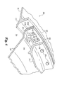
- Fig. 4 there is illustrated a perspective sectional view of some aspects of a non-limiting example of flange assembly 300 in accordance with an embodiment of the present invention. While only a portion of flange assembly 300 is illustrated in Fig. 4 , it is contemplated that flange assembly 300 could extend about all or a portion of the circumference of cases 311 and 331. Features described above in connection with Fig. 3 are indicated with identical reference numerals in Fig. 4 .
- Fasteners 370 may pass through flanges 310, 320 and 330 and shim plates 312A and 312B to fasten the flange assembly 300 together. Additional embodiments contemplate other means for fastening flange assembly 300 including welding, other fasteners, and/or combinations of these and other techniques.
- fillet cavity 317 which extends along the entire circumference of flange assembly 300.
- fillet cavity 317 can extend along only a portion of the circumference of flange assembly 300.
- a number of fillet cavities can extend along portions of the circumference of flange assembly 300. Flow can proceed in either direction along fillet cavity 317 and into passage 319 opposite recess 316.
- the number of recesses 316 provided in flange assembly 300 may vary, e.g., depending upon the desired amount of flow through flange assembly 300. As illustrated in Fig.
- passages 319 there are a number of passages 319 provided in flange assembly 300. Furthermore, there may also be additional recesses similar to recess 316 provided in flange assembly 300. From passages 319, flow proceeds through holes 318 provided in flange 320. In the embodiment illustrated in Fig. 4 , two holes 318 are positioned near the distal corners of the passage 319. This position provides a preferred fluid flow through passage 319. Other embodiments contemplate different numbers and positioning of holes, for example, one, three, four or more holes could be provided in a variety of positions. Further embodiments contemplate that the holes could be a variety of different shapes, for example, ellipsoid shapes, slots, and other openings could be provided in flange 320.
- flange 320 may extend radially along only part of flanges 310 and 330 and one or more flow paths could be positioned at an end of flange 320.
- An additional structure could be positioned intermediate flanges 310 and 330 to define one or more flow paths positioned at the end of flange 320.
- a portion of flange 310, flange 330, or both could extend to define the flow path(s) positioned at the end of flange 320.
- FIG. 5 there is illustrated a perspective view of some aspects of a non-limiting example of a portion of flange assembly 300 in accordance with an embodiment of the present invention. While only a portion of flange assembly 300 is illustrated in Fig. 5 , it is contemplated that flange assembly 300 could extend about all or a portion of the circumference of cases 311 and 331. Features described above in connection with Figs. 3 and 4 are indicated with identical reference numerals in Fig. 5 . Arrows F illustrate the flow of fluid through flange assembly 300. As indicated by arrows F, fluid flows from holes 318 into passages 329. From passages 329, fluid flow enters fillet cavity 327 which extends along the circumference of flange assembly 300.
- fillet cavity 327 can extend along a portion of the circumference of flange assembly 300. In other embodiments, a number of fillet cavities can extends along portions of the circumference of flange assembly 300. From fillet cavity 327, fluid flow can proceed in either direction along fillet cavity 327, or can enter recess 326. From recess 326, flow enters lower pressure cavity 350.
- the number of recesses 326 provided in flange assembly 300 may vary, e.g., depending upon the desired amount of flow through flange assembly 300. Recesses 316 and 326 and passages 319 and 329 are preferably intermittently spaced so that they do not interfere with the piloting provided by flanges 310, 320 and 330.
- the flow circuit of flange assembly 300 can provide desirable thermal response.
- outer combustor case 311 is subjected to high temperatures resulting from the combustion process in the combustor section of a gas turbine engine.
- the flange assembly 300 is subjected to the relatively lower temperature of its environment.
- a temperature mismatch between the case 311 and the flange assembly 300 can result and may produce undesirable thermally induced stress.
- Flow through the flow circuit provided in flange assembly 300 can increase the thermal response of the flange assembly and decrease the temperature mismatch and thermally induce stress that might otherwise be present.
- Embodiments of the present invention include an apparatus comprising: a gas turbine engine flange assembly including: a first flange, a second flange, and a third flange, the second flange being positioned intermediate the first flange and the third flange; and a fluid flow circuit extending intermediate the first flange and the second flange, across the second flange, and intermediate the second flange and the third flange.
- the apparatus further comprises a shim plate positioned intermediate the first flange and the second flange.
- the apparatus further comprises a shim plate positioned intermediate the second flange and the third flange, the shim plate defining a boundary of a portion of the fluid flow circuit.
- the apparatus further comprises a fillet cavity intermediate the first flange and the second flange.
- the apparatus further comprises a fillet cavity intermediate the second flange and the third flange, the fillet cavity defining a boundary of a portion of the fluid flow circuit.
- the apparatus further comprises a recess provided in one of the first flange, the second flange, and the third flange, the recess defining a boundary of a portion of the fluid flow circuit.
- the apparatus further comprises means for routing fluid flow through the flange assembly.
- the flow circuit extends from a higher pressure cavity to a lower pressure cavity and includes a first recess provided in the second flange, a first fillet cavity intermediate the first flange and the second flange, a first passage bordered by first a shim plate, the first flange and the second flange, at least one opening provided in the second flange, a second passage bordered by a second shim plate, the second flange and the third flange, a second fillet cavity intermediate the second flange and the third flange, and a second recess provided in the second flange.
- the first flange extends from a compressor case, and the third flange extends from an outer combustor case.
- the first flange extends from an outer combustor case, and the third flange extends from a turbine case.
- the first flange extends from a combustor case, and the third flange extends from an afterburner case.
- the second flange extends from a support.
- Embodiments of the present invention include a system comprising: a first gas turbine engine case; a second gas turbine engine case; a flange assembly coupling the first gas turbine engine case and the second gas turbine engine case, the flange assembly extending circumferentially about at least a portion of the first gas turbine engine case; and a fluid flow circuit extending from a cavity within the first gas turbine engine case to an interior portion of the flange assembly.
- the flange assembly includes a first flange, a second flange, and a third flange, the second flange being positioned intermediate the first flange and the third flange.
- the fluid flow circuit extends from a higher pressure cavity to a lower pressure cavity and includes a first flow passage intermediate the first flange and the second flange, an opening provided in the second flange, and a second flow passage intermediate the second flange and the third flange.
- the first gas turbine engine case is a combustor case and the second gas turbine engine case is a compressor case.
- the first gas turbine engine case is a combustor case and the second gas turbine engine case is a turbine case.
- the first gas turbine engine case is an afterburner case and the second gas turbine engine case is a turbine case.
- Embodiments of the present invention include a method comprising: operating a gas turbine engine including a compressor, a combustor, a turbine, a flange assembly including a first flange extending from an engine case, a second flange, and a third flange; generating a temperature differential between a portion of the engine case and the flange assembly based upon the operating; and flowing fluid through a flow circuit in the flange assembly effective to reduce the temperature differential.
- the flowing fluid through a flow circuit in the flange includes flowing fluid through a passage intermediate the first flange and the second flange.
- the flowing fluid through a flow circuit in the flange includes flowing fluid through a hole provided in the second flange.
- the engine case is an outer combustor case.
Landscapes
- Engineering & Computer Science (AREA)
- Mechanical Engineering (AREA)
- General Engineering & Computer Science (AREA)
- Structures Of Non-Positive Displacement Pumps (AREA)
- Turbine Rotor Nozzle Sealing (AREA)
Applications Claiming Priority (1)
| Application Number | Priority Date | Filing Date | Title |
|---|---|---|---|
| US201061428765P | 2010-12-30 | 2010-12-30 |
Publications (3)
| Publication Number | Publication Date |
|---|---|
| EP2472068A2 true EP2472068A2 (de) | 2012-07-04 |
| EP2472068A3 EP2472068A3 (de) | 2014-03-19 |
| EP2472068B1 EP2472068B1 (de) | 2017-11-29 |
Family
ID=45478173
Family Applications (1)
| Application Number | Title | Priority Date | Filing Date |
|---|---|---|---|
| EP11250946.8A Not-in-force EP2472068B1 (de) | 2010-12-30 | 2011-12-28 | Gasturbinentriebwerkflanschanordnung mit Durchflusskanal |
Country Status (3)
| Country | Link |
|---|---|
| US (1) | US8899051B2 (de) |
| EP (1) | EP2472068B1 (de) |
| CA (1) | CA2762835C (de) |
Cited By (1)
| Publication number | Priority date | Publication date | Assignee | Title |
|---|---|---|---|---|
| WO2016068858A1 (en) * | 2014-10-28 | 2016-05-06 | Siemens Aktiengesellschaft | Flange cooling system for hot gas path plenums in a turbine engine |
Families Citing this family (6)
| Publication number | Priority date | Publication date | Assignee | Title |
|---|---|---|---|---|
| US9850780B2 (en) | 2012-12-29 | 2017-12-26 | United Technologies Corporation | Plate for directing flow and film cooling of components |
| US9206742B2 (en) * | 2012-12-29 | 2015-12-08 | United Technologies Corporation | Passages to facilitate a secondary flow between components |
| US9856753B2 (en) | 2015-06-10 | 2018-01-02 | United Technologies Corporation | Inner diameter scallop case flange for a case of a gas turbine engine |
| US20190368381A1 (en) * | 2018-05-30 | 2019-12-05 | General Electric Company | Combustion System Deflection Mitigation Structure |
| US11814977B1 (en) | 2022-08-29 | 2023-11-14 | Rtx Corporation | Thermal conditioning of flange with secondary flow |
| US12221895B1 (en) * | 2023-08-02 | 2025-02-11 | Rtx Corporation | Steam heated flange for thermal gradient control |
Family Cites Families (31)
| Publication number | Priority date | Publication date | Assignee | Title |
|---|---|---|---|---|
| US4912922A (en) | 1972-12-19 | 1990-04-03 | General Electric Company | Combustion chamber construction |
| US4614082A (en) * | 1972-12-19 | 1986-09-30 | General Electric Company | Combustion chamber construction |
| US3854285A (en) * | 1973-02-26 | 1974-12-17 | Gen Electric | Combustor dome assembly |
| US4785623A (en) | 1987-12-09 | 1988-11-22 | United Technologies Corporation | Combustor seal and support |
| JPH03213602A (ja) | 1990-01-08 | 1991-09-19 | General Electric Co <Ge> | ガスタービンエンジンの当接セグメントを連結する自己冷却式ジョイント連結構造 |
| FR2686683B1 (fr) | 1992-01-28 | 1994-04-01 | Snecma | Turbomachine a chambre de combustion demontable. |
| US5219268A (en) | 1992-03-06 | 1993-06-15 | General Electric Company | Gas turbine engine case thermal control flange |
| DE4324035C2 (de) | 1993-07-17 | 2003-02-27 | Alstom | Gasturbine |
| US5593277A (en) * | 1995-06-06 | 1997-01-14 | General Electric Company | Smart turbine shroud |
| US5701733A (en) | 1995-12-22 | 1997-12-30 | General Electric Company | Double rabbet combustor mount |
| US5755556A (en) * | 1996-05-17 | 1998-05-26 | Westinghouse Electric Corporation | Turbomachine rotor with improved cooling |
| ATE248315T1 (de) * | 1997-06-25 | 2003-09-15 | Siemens Ag | Vorrichtung zum verbinden von leitungsabschnitten |
| US6352404B1 (en) | 2000-02-18 | 2002-03-05 | General Electric Company | Thermal control passages for horizontal split-line flanges of gas turbine engine casings |
| US6389813B2 (en) | 2000-03-31 | 2002-05-21 | Quiet Systems International, Llc | Passive mounted lining system |
| US6499993B2 (en) | 2000-05-25 | 2002-12-31 | General Electric Company | External dilution air tuning for dry low NOX combustors and methods therefor |
| US6401447B1 (en) | 2000-11-08 | 2002-06-11 | Allison Advanced Development Company | Combustor apparatus for a gas turbine engine |
| US6536201B2 (en) | 2000-12-11 | 2003-03-25 | Pratt & Whitney Canada Corp. | Combustor turbine successive dual cooling |
| US6588214B2 (en) | 2001-10-09 | 2003-07-08 | Power Systems Mfg, Llc | Wear reduction means for a gas turbine combustor transition duct end frame |
| US6886343B2 (en) | 2003-01-15 | 2005-05-03 | General Electric Company | Methods and apparatus for controlling engine clearance closures |
| US6860108B2 (en) | 2003-01-22 | 2005-03-01 | Mitsubishi Heavy Industries, Ltd. | Gas turbine tail tube seal and gas turbine using the same |
| US7093440B2 (en) | 2003-06-11 | 2006-08-22 | General Electric Company | Floating liner combustor |
| US7152411B2 (en) | 2003-06-27 | 2006-12-26 | General Electric Company | Rabbet mounted combuster |
| US6955038B2 (en) | 2003-07-02 | 2005-10-18 | General Electric Company | Methods and apparatus for operating gas turbine engine combustors |
| US7093419B2 (en) | 2003-07-02 | 2006-08-22 | General Electric Company | Methods and apparatus for operating gas turbine engine combustors |
| US7036316B2 (en) | 2003-10-17 | 2006-05-02 | General Electric Company | Methods and apparatus for cooling turbine engine combustor exit temperatures |
| US7000406B2 (en) | 2003-12-03 | 2006-02-21 | Pratt & Whitney Canada Corp. | Gas turbine combustor sliding joint |
| GB0403198D0 (en) | 2004-02-13 | 2004-03-17 | Rolls Royce Plc | Casing arrangement |
| US7082765B2 (en) | 2004-09-01 | 2006-08-01 | General Electric Company | Methods and apparatus for reducing gas turbine engine emissions |
| US7278254B2 (en) | 2005-01-27 | 2007-10-09 | Siemens Power Generation, Inc. | Cooling system for a transition bracket of a transition in a turbine engine |
| US7797948B2 (en) | 2007-03-27 | 2010-09-21 | Siemens Energy, Inc. | Transition-to-turbine seal apparatus and transition-to-turbine seal junction of a gas turbine engine |
| US8147178B2 (en) * | 2008-12-23 | 2012-04-03 | General Electric Company | Centrifugal compressor forward thrust and turbine cooling apparatus |
-
2011
- 2011-12-24 US US13/337,111 patent/US8899051B2/en active Active
- 2011-12-28 EP EP11250946.8A patent/EP2472068B1/de not_active Not-in-force
- 2011-12-29 CA CA2762835A patent/CA2762835C/en not_active Expired - Fee Related
Non-Patent Citations (1)
| Title |
|---|
| None |
Cited By (1)
| Publication number | Priority date | Publication date | Assignee | Title |
|---|---|---|---|---|
| WO2016068858A1 (en) * | 2014-10-28 | 2016-05-06 | Siemens Aktiengesellschaft | Flange cooling system for hot gas path plenums in a turbine engine |
Also Published As
| Publication number | Publication date |
|---|---|
| US20120192567A1 (en) | 2012-08-02 |
| EP2472068B1 (de) | 2017-11-29 |
| CA2762835C (en) | 2018-06-05 |
| EP2472068A3 (de) | 2014-03-19 |
| CA2762835A1 (en) | 2012-06-30 |
| US8899051B2 (en) | 2014-12-02 |
Similar Documents
| Publication | Publication Date | Title |
|---|---|---|
| US8899051B2 (en) | Gas turbine engine flange assembly including flow circuit | |
| US11143106B2 (en) | Combustion section heat transfer system for a propulsion system | |
| US9982630B2 (en) | Turbofan bypass air cooled oil cooler fairings | |
| US10126062B2 (en) | Heat exchanger for embedded engine applications | |
| JP6179956B2 (ja) | 熱交換器組立体(60)及びモジュール式放射状管体型熱交換器(60)を組み立てる方法 | |
| US11002290B2 (en) | Heat exchanger for embedded engine applications: curvilinear plate | |
| EP3190272A1 (de) | Verfahren zum kühlen einer flüssigkeit unter verwendung eines ringförmigen wärmetauschers | |
| US10364681B2 (en) | Turbine blade | |
| EP2860354B1 (de) | Stützstrebenanordnung mit integrierten Turbinenleitschaufeln | |
| US10830051B2 (en) | Engine component with film cooling | |
| EP2977617B1 (de) | Abblasventil mit im verschlussorgan integrierter resonanzkammer | |
| EP3591292B1 (de) | Löschöffnungskörper für eine gasturbinenbrennkammer | |
| US11208901B2 (en) | Trailing edge cooling for a turbine blade | |
| US20160123186A1 (en) | Shroud assembly for a turbine engine | |
| EP3366909A1 (de) | Turbinenmotor mit thermischer dichtung | |
| US10428834B2 (en) | Turbine engine cooler assembly | |
| EP2420652A2 (de) | Verteilermontageanordnung | |
| EP3246519B1 (de) | Aktiv gekühltes bauteil | |
| US10920613B2 (en) | Retention system for improved fire protection | |
| EP3848570B1 (de) | Kühlsystem für ein gasturbinentriebwerk | |
| EP2613005B1 (de) | Turbomaschinenkomponente mit einer Abdeckplatte | |
| EP4678900A1 (de) | Motorintegrierter wärmetauscher | |
| US20180149169A1 (en) | Support structure for radial inlet of gas turbine engine | |
| EP3604926B1 (de) | Hitzeschildkachel zur verwendung in einer gasturbinenbrennkammer | |
| CA2967099A1 (en) | Actively cooled component |
Legal Events
| Date | Code | Title | Description |
|---|---|---|---|
| AK | Designated contracting states |
Kind code of ref document: A2 Designated state(s): AL AT BE BG CH CY CZ DE DK EE ES FI FR GB GR HR HU IE IS IT LI LT LU LV MC MK MT NL NO PL PT RO RS SE SI SK SM TR |
|
| AX | Request for extension of the european patent |
Extension state: BA ME |
|
| PUAI | Public reference made under article 153(3) epc to a published international application that has entered the european phase |
Free format text: ORIGINAL CODE: 0009012 |
|
| PUAL | Search report despatched |
Free format text: ORIGINAL CODE: 0009013 |
|
| AK | Designated contracting states |
Kind code of ref document: A3 Designated state(s): AL AT BE BG CH CY CZ DE DK EE ES FI FR GB GR HR HU IE IS IT LI LT LU LV MC MK MT NL NO PL PT RO RS SE SI SK SM TR |
|
| AX | Request for extension of the european patent |
Extension state: BA ME |
|
| RIC1 | Information provided on ipc code assigned before grant |
Ipc: F01D 25/14 20060101ALI20140212BHEP Ipc: F01D 25/24 20060101ALI20140212BHEP Ipc: F01D 25/12 20060101AFI20140212BHEP |
|
| 17P | Request for examination filed |
Effective date: 20140804 |
|
| RBV | Designated contracting states (corrected) |
Designated state(s): AL AT BE BG CH CY CZ DE DK EE ES FI FR GB GR HR HU IE IS IT LI LT LU LV MC MK MT NL NO PL PT RO RS SE SI SK SM TR |
|
| GRAP | Despatch of communication of intention to grant a patent |
Free format text: ORIGINAL CODE: EPIDOSNIGR1 |
|
| GRAJ | Information related to disapproval of communication of intention to grant by the applicant or resumption of examination proceedings by the epo deleted |
Free format text: ORIGINAL CODE: EPIDOSDIGR1 |
|
| GRAP | Despatch of communication of intention to grant a patent |
Free format text: ORIGINAL CODE: EPIDOSNIGR1 |
|
| INTG | Intention to grant announced |
Effective date: 20160926 |
|
| INTG | Intention to grant announced |
Effective date: 20161026 |
|
| GRAJ | Information related to disapproval of communication of intention to grant by the applicant or resumption of examination proceedings by the epo deleted |
Free format text: ORIGINAL CODE: EPIDOSDIGR1 |
|
| STAA | Information on the status of an ep patent application or granted ep patent |
Free format text: STATUS: REQUEST FOR EXAMINATION WAS MADE |
|
| INTC | Intention to grant announced (deleted) | ||
| STAA | Information on the status of an ep patent application or granted ep patent |
Free format text: STATUS: EXAMINATION IS IN PROGRESS |
|
| 17Q | First examination report despatched |
Effective date: 20170509 |
|
| GRAR | Information related to intention to grant a patent recorded |
Free format text: ORIGINAL CODE: EPIDOSNIGR71 |
|
| GRAS | Grant fee paid |
Free format text: ORIGINAL CODE: EPIDOSNIGR3 |
|
| STAA | Information on the status of an ep patent application or granted ep patent |
Free format text: STATUS: GRANT OF PATENT IS INTENDED |
|
| GRAA | (expected) grant |
Free format text: ORIGINAL CODE: 0009210 |
|
| STAA | Information on the status of an ep patent application or granted ep patent |
Free format text: STATUS: THE PATENT HAS BEEN GRANTED |
|
| AK | Designated contracting states |
Kind code of ref document: B1 Designated state(s): AL AT BE BG CH CY CZ DE DK EE ES FI FR GB GR HR HU IE IS IT LI LT LU LV MC MK MT NL NO PL PT RO RS SE SI SK SM TR |
|
| INTG | Intention to grant announced |
Effective date: 20171023 |
|
| REG | Reference to a national code |
Ref country code: CH Ref legal event code: EP |
|
| REG | Reference to a national code |
Ref country code: AT Ref legal event code: REF Ref document number: 950595 Country of ref document: AT Kind code of ref document: T Effective date: 20171215 |
|
| REG | Reference to a national code |
Ref country code: IE Ref legal event code: FG4D Ref country code: FR Ref legal event code: PLFP Year of fee payment: 7 |
|
| REG | Reference to a national code |
Ref country code: DE Ref legal event code: R096 Ref document number: 602011043743 Country of ref document: DE |
|
| REG | Reference to a national code |
Ref country code: NL Ref legal event code: MP Effective date: 20171129 |
|
| REG | Reference to a national code |
Ref country code: LT Ref legal event code: MG4D |
|
| REG | Reference to a national code |
Ref country code: AT Ref legal event code: MK05 Ref document number: 950595 Country of ref document: AT Kind code of ref document: T Effective date: 20171129 |
|
| PG25 | Lapsed in a contracting state [announced via postgrant information from national office to epo] |
Ref country code: SE Free format text: LAPSE BECAUSE OF FAILURE TO SUBMIT A TRANSLATION OF THE DESCRIPTION OR TO PAY THE FEE WITHIN THE PRESCRIBED TIME-LIMIT Effective date: 20171129 Ref country code: FI Free format text: LAPSE BECAUSE OF FAILURE TO SUBMIT A TRANSLATION OF THE DESCRIPTION OR TO PAY THE FEE WITHIN THE PRESCRIBED TIME-LIMIT Effective date: 20171129 Ref country code: NO Free format text: LAPSE BECAUSE OF FAILURE TO SUBMIT A TRANSLATION OF THE DESCRIPTION OR TO PAY THE FEE WITHIN THE PRESCRIBED TIME-LIMIT Effective date: 20180228 Ref country code: ES Free format text: LAPSE BECAUSE OF FAILURE TO SUBMIT A TRANSLATION OF THE DESCRIPTION OR TO PAY THE FEE WITHIN THE PRESCRIBED TIME-LIMIT Effective date: 20171129 Ref country code: LT Free format text: LAPSE BECAUSE OF FAILURE TO SUBMIT A TRANSLATION OF THE DESCRIPTION OR TO PAY THE FEE WITHIN THE PRESCRIBED TIME-LIMIT Effective date: 20171129 |
|
| PG25 | Lapsed in a contracting state [announced via postgrant information from national office to epo] |
Ref country code: AT Free format text: LAPSE BECAUSE OF FAILURE TO SUBMIT A TRANSLATION OF THE DESCRIPTION OR TO PAY THE FEE WITHIN THE PRESCRIBED TIME-LIMIT Effective date: 20171129 Ref country code: HR Free format text: LAPSE BECAUSE OF FAILURE TO SUBMIT A TRANSLATION OF THE DESCRIPTION OR TO PAY THE FEE WITHIN THE PRESCRIBED TIME-LIMIT Effective date: 20171129 Ref country code: GR Free format text: LAPSE BECAUSE OF FAILURE TO SUBMIT A TRANSLATION OF THE DESCRIPTION OR TO PAY THE FEE WITHIN THE PRESCRIBED TIME-LIMIT Effective date: 20180301 Ref country code: LV Free format text: LAPSE BECAUSE OF FAILURE TO SUBMIT A TRANSLATION OF THE DESCRIPTION OR TO PAY THE FEE WITHIN THE PRESCRIBED TIME-LIMIT Effective date: 20171129 Ref country code: BG Free format text: LAPSE BECAUSE OF FAILURE TO SUBMIT A TRANSLATION OF THE DESCRIPTION OR TO PAY THE FEE WITHIN THE PRESCRIBED TIME-LIMIT Effective date: 20180228 Ref country code: RS Free format text: LAPSE BECAUSE OF FAILURE TO SUBMIT A TRANSLATION OF THE DESCRIPTION OR TO PAY THE FEE WITHIN THE PRESCRIBED TIME-LIMIT Effective date: 20171129 |
|
| PG25 | Lapsed in a contracting state [announced via postgrant information from national office to epo] |
Ref country code: NL Free format text: LAPSE BECAUSE OF FAILURE TO SUBMIT A TRANSLATION OF THE DESCRIPTION OR TO PAY THE FEE WITHIN THE PRESCRIBED TIME-LIMIT Effective date: 20171129 |
|
| PG25 | Lapsed in a contracting state [announced via postgrant information from national office to epo] |
Ref country code: SK Free format text: LAPSE BECAUSE OF FAILURE TO SUBMIT A TRANSLATION OF THE DESCRIPTION OR TO PAY THE FEE WITHIN THE PRESCRIBED TIME-LIMIT Effective date: 20171129 Ref country code: EE Free format text: LAPSE BECAUSE OF FAILURE TO SUBMIT A TRANSLATION OF THE DESCRIPTION OR TO PAY THE FEE WITHIN THE PRESCRIBED TIME-LIMIT Effective date: 20171129 Ref country code: CY Free format text: LAPSE BECAUSE OF FAILURE TO SUBMIT A TRANSLATION OF THE DESCRIPTION OR TO PAY THE FEE WITHIN THE PRESCRIBED TIME-LIMIT Effective date: 20171129 Ref country code: DK Free format text: LAPSE BECAUSE OF FAILURE TO SUBMIT A TRANSLATION OF THE DESCRIPTION OR TO PAY THE FEE WITHIN THE PRESCRIBED TIME-LIMIT Effective date: 20171129 Ref country code: CZ Free format text: LAPSE BECAUSE OF FAILURE TO SUBMIT A TRANSLATION OF THE DESCRIPTION OR TO PAY THE FEE WITHIN THE PRESCRIBED TIME-LIMIT Effective date: 20171129 |
|
| REG | Reference to a national code |
Ref country code: CH Ref legal event code: PL |
|
| REG | Reference to a national code |
Ref country code: DE Ref legal event code: R097 Ref document number: 602011043743 Country of ref document: DE |
|
| PG25 | Lapsed in a contracting state [announced via postgrant information from national office to epo] |
Ref country code: IT Free format text: LAPSE BECAUSE OF FAILURE TO SUBMIT A TRANSLATION OF THE DESCRIPTION OR TO PAY THE FEE WITHIN THE PRESCRIBED TIME-LIMIT Effective date: 20171129 Ref country code: SM Free format text: LAPSE BECAUSE OF FAILURE TO SUBMIT A TRANSLATION OF THE DESCRIPTION OR TO PAY THE FEE WITHIN THE PRESCRIBED TIME-LIMIT Effective date: 20171129 Ref country code: PL Free format text: LAPSE BECAUSE OF FAILURE TO SUBMIT A TRANSLATION OF THE DESCRIPTION OR TO PAY THE FEE WITHIN THE PRESCRIBED TIME-LIMIT Effective date: 20171129 Ref country code: RO Free format text: LAPSE BECAUSE OF FAILURE TO SUBMIT A TRANSLATION OF THE DESCRIPTION OR TO PAY THE FEE WITHIN THE PRESCRIBED TIME-LIMIT Effective date: 20171129 |
|
| REG | Reference to a national code |
Ref country code: IE Ref legal event code: MM4A |
|
| PG25 | Lapsed in a contracting state [announced via postgrant information from national office to epo] |
Ref country code: LU Free format text: LAPSE BECAUSE OF NON-PAYMENT OF DUE FEES Effective date: 20171228 Ref country code: MT Free format text: LAPSE BECAUSE OF NON-PAYMENT OF DUE FEES Effective date: 20171228 |
|
| PLBE | No opposition filed within time limit |
Free format text: ORIGINAL CODE: 0009261 |
|
| STAA | Information on the status of an ep patent application or granted ep patent |
Free format text: STATUS: NO OPPOSITION FILED WITHIN TIME LIMIT |
|
| REG | Reference to a national code |
Ref country code: BE Ref legal event code: MM Effective date: 20171231 |
|
| GBPC | Gb: european patent ceased through non-payment of renewal fee |
Effective date: 20180228 |
|
| PG25 | Lapsed in a contracting state [announced via postgrant information from national office to epo] |
Ref country code: IE Free format text: LAPSE BECAUSE OF NON-PAYMENT OF DUE FEES Effective date: 20171228 |
|
| 26N | No opposition filed |
Effective date: 20180830 |
|
| PG25 | Lapsed in a contracting state [announced via postgrant information from national office to epo] |
Ref country code: SI Free format text: LAPSE BECAUSE OF FAILURE TO SUBMIT A TRANSLATION OF THE DESCRIPTION OR TO PAY THE FEE WITHIN THE PRESCRIBED TIME-LIMIT Effective date: 20171129 Ref country code: BE Free format text: LAPSE BECAUSE OF NON-PAYMENT OF DUE FEES Effective date: 20171231 Ref country code: LI Free format text: LAPSE BECAUSE OF NON-PAYMENT OF DUE FEES Effective date: 20171231 Ref country code: CH Free format text: LAPSE BECAUSE OF NON-PAYMENT OF DUE FEES Effective date: 20171231 |
|
| PG25 | Lapsed in a contracting state [announced via postgrant information from national office to epo] |
Ref country code: GB Free format text: LAPSE BECAUSE OF NON-PAYMENT OF DUE FEES Effective date: 20180228 |
|
| PG25 | Lapsed in a contracting state [announced via postgrant information from national office to epo] |
Ref country code: HU Free format text: LAPSE BECAUSE OF FAILURE TO SUBMIT A TRANSLATION OF THE DESCRIPTION OR TO PAY THE FEE WITHIN THE PRESCRIBED TIME-LIMIT; INVALID AB INITIO Effective date: 20111228 Ref country code: MC Free format text: LAPSE BECAUSE OF FAILURE TO SUBMIT A TRANSLATION OF THE DESCRIPTION OR TO PAY THE FEE WITHIN THE PRESCRIBED TIME-LIMIT Effective date: 20171129 |
|
| PG25 | Lapsed in a contracting state [announced via postgrant information from national office to epo] |
Ref country code: MK Free format text: LAPSE BECAUSE OF FAILURE TO SUBMIT A TRANSLATION OF THE DESCRIPTION OR TO PAY THE FEE WITHIN THE PRESCRIBED TIME-LIMIT Effective date: 20171129 |
|
| PGFP | Annual fee paid to national office [announced via postgrant information from national office to epo] |
Ref country code: FR Payment date: 20191226 Year of fee payment: 9 |
|
| PG25 | Lapsed in a contracting state [announced via postgrant information from national office to epo] |
Ref country code: TR Free format text: LAPSE BECAUSE OF FAILURE TO SUBMIT A TRANSLATION OF THE DESCRIPTION OR TO PAY THE FEE WITHIN THE PRESCRIBED TIME-LIMIT Effective date: 20171129 |
|
| PG25 | Lapsed in a contracting state [announced via postgrant information from national office to epo] |
Ref country code: PT Free format text: LAPSE BECAUSE OF FAILURE TO SUBMIT A TRANSLATION OF THE DESCRIPTION OR TO PAY THE FEE WITHIN THE PRESCRIBED TIME-LIMIT Effective date: 20171129 |
|
| PG25 | Lapsed in a contracting state [announced via postgrant information from national office to epo] |
Ref country code: AL Free format text: LAPSE BECAUSE OF FAILURE TO SUBMIT A TRANSLATION OF THE DESCRIPTION OR TO PAY THE FEE WITHIN THE PRESCRIBED TIME-LIMIT Effective date: 20171129 Ref country code: IS Free format text: LAPSE BECAUSE OF FAILURE TO SUBMIT A TRANSLATION OF THE DESCRIPTION OR TO PAY THE FEE WITHIN THE PRESCRIBED TIME-LIMIT Effective date: 20180329 |
|
| PG25 | Lapsed in a contracting state [announced via postgrant information from national office to epo] |
Ref country code: FR Free format text: LAPSE BECAUSE OF NON-PAYMENT OF DUE FEES Effective date: 20201231 |
|
| P01 | Opt-out of the competence of the unified patent court (upc) registered |
Effective date: 20230528 |
|
| PGFP | Annual fee paid to national office [announced via postgrant information from national office to epo] |
Ref country code: DE Payment date: 20231227 Year of fee payment: 13 |
|
| REG | Reference to a national code |
Ref country code: DE Ref legal event code: R119 Ref document number: 602011043743 Country of ref document: DE |
|
| PG25 | Lapsed in a contracting state [announced via postgrant information from national office to epo] |
Ref country code: DE Free format text: LAPSE BECAUSE OF NON-PAYMENT OF DUE FEES Effective date: 20250701 |