EP2471613A2 - Assemblage de noyau de moulage et procédé de fabrication - Google Patents
Assemblage de noyau de moulage et procédé de fabrication Download PDFInfo
- Publication number
- EP2471613A2 EP2471613A2 EP11195322A EP11195322A EP2471613A2 EP 2471613 A2 EP2471613 A2 EP 2471613A2 EP 11195322 A EP11195322 A EP 11195322A EP 11195322 A EP11195322 A EP 11195322A EP 2471613 A2 EP2471613 A2 EP 2471613A2
- Authority
- EP
- European Patent Office
- Prior art keywords
- core
- ceramic
- plug
- metallic
- moulding
- Prior art date
- Legal status (The legal status is an assumption and is not a legal conclusion. Google has not performed a legal analysis and makes no representation as to the accuracy of the status listed.)
- Withdrawn
Links
- 238000005266 casting Methods 0.000 title claims abstract description 37
- 238000004519 manufacturing process Methods 0.000 title description 5
- 239000000919 ceramic Substances 0.000 claims abstract description 59
- 238000000034 method Methods 0.000 claims abstract description 53
- 239000000853 adhesive Substances 0.000 claims abstract description 12
- 230000001070 adhesive effect Effects 0.000 claims abstract description 12
- 239000000463 material Substances 0.000 claims description 33
- 238000000465 moulding Methods 0.000 claims description 27
- 230000000873 masking effect Effects 0.000 claims description 10
- 238000000576 coating method Methods 0.000 claims description 8
- 239000011248 coating agent Substances 0.000 claims description 7
- 229910000951 Aluminide Inorganic materials 0.000 claims description 6
- 238000010438 heat treatment Methods 0.000 claims description 2
- 239000002184 metal Substances 0.000 claims 2
- 238000007493 shaping process Methods 0.000 claims 1
- 239000001993 wax Substances 0.000 description 16
- 238000001816 cooling Methods 0.000 description 10
- VYPSYNLAJGMNEJ-UHFFFAOYSA-N Silicium dioxide Chemical compound O=[Si]=O VYPSYNLAJGMNEJ-UHFFFAOYSA-N 0.000 description 9
- 239000010410 layer Substances 0.000 description 9
- 239000003870 refractory metal Substances 0.000 description 9
- 229910045601 alloy Inorganic materials 0.000 description 7
- 239000000956 alloy Substances 0.000 description 7
- 239000011230 binding agent Substances 0.000 description 5
- 238000005520 cutting process Methods 0.000 description 5
- 239000007789 gas Substances 0.000 description 5
- 239000000203 mixture Substances 0.000 description 5
- 239000002002 slurry Substances 0.000 description 5
- 229910000601 superalloy Inorganic materials 0.000 description 5
- OKTJSMMVPCPJKN-UHFFFAOYSA-N Carbon Chemical compound [C] OKTJSMMVPCPJKN-UHFFFAOYSA-N 0.000 description 4
- PNEYBMLMFCGWSK-UHFFFAOYSA-N aluminium oxide Inorganic materials [O-2].[O-2].[O-2].[Al+3].[Al+3] PNEYBMLMFCGWSK-UHFFFAOYSA-N 0.000 description 4
- 229910052799 carbon Inorganic materials 0.000 description 4
- 230000008901 benefit Effects 0.000 description 3
- 238000005495 investment casting Methods 0.000 description 3
- 238000003754 machining Methods 0.000 description 3
- 239000000843 powder Substances 0.000 description 3
- 239000000377 silicon dioxide Substances 0.000 description 3
- CURLTUGMZLYLDI-UHFFFAOYSA-N Carbon dioxide Chemical compound O=C=O CURLTUGMZLYLDI-UHFFFAOYSA-N 0.000 description 2
- ZOKXTWBITQBERF-UHFFFAOYSA-N Molybdenum Chemical compound [Mo] ZOKXTWBITQBERF-UHFFFAOYSA-N 0.000 description 2
- PXHVJJICTQNCMI-UHFFFAOYSA-N Nickel Chemical compound [Ni] PXHVJJICTQNCMI-UHFFFAOYSA-N 0.000 description 2
- 238000005452 bending Methods 0.000 description 2
- 230000015572 biosynthetic process Effects 0.000 description 2
- 238000005229 chemical vapour deposition Methods 0.000 description 2
- 239000008119 colloidal silica Substances 0.000 description 2
- 239000013078 crystal Substances 0.000 description 2
- 229910052750 molybdenum Inorganic materials 0.000 description 2
- 239000011733 molybdenum Substances 0.000 description 2
- 229910052758 niobium Inorganic materials 0.000 description 2
- 239000010955 niobium Substances 0.000 description 2
- GUCVJGMIXFAOAE-UHFFFAOYSA-N niobium atom Chemical compound [Nb] GUCVJGMIXFAOAE-UHFFFAOYSA-N 0.000 description 2
- 230000003647 oxidation Effects 0.000 description 2
- 238000007254 oxidation reaction Methods 0.000 description 2
- 230000001590 oxidative effect Effects 0.000 description 2
- 239000012188 paraffin wax Substances 0.000 description 2
- BASFCYQUMIYNBI-UHFFFAOYSA-N platinum Chemical compound [Pt] BASFCYQUMIYNBI-UHFFFAOYSA-N 0.000 description 2
- 239000011253 protective coating Substances 0.000 description 2
- 238000007711 solidification Methods 0.000 description 2
- 230000008023 solidification Effects 0.000 description 2
- 239000000758 substrate Substances 0.000 description 2
- 229910000760 Hardened steel Inorganic materials 0.000 description 1
- 239000002253 acid Substances 0.000 description 1
- 230000003466 anti-cipated effect Effects 0.000 description 1
- 230000000712 assembly Effects 0.000 description 1
- 238000000429 assembly Methods 0.000 description 1
- QVGXLLKOCUKJST-UHFFFAOYSA-N atomic oxygen Chemical compound [O] QVGXLLKOCUKJST-UHFFFAOYSA-N 0.000 description 1
- 239000011324 bead Substances 0.000 description 1
- 229910002092 carbon dioxide Inorganic materials 0.000 description 1
- 239000001569 carbon dioxide Substances 0.000 description 1
- 239000010941 cobalt Substances 0.000 description 1
- 229910017052 cobalt Inorganic materials 0.000 description 1
- GUTLYIVDDKVIGB-UHFFFAOYSA-N cobalt atom Chemical compound [Co] GUTLYIVDDKVIGB-UHFFFAOYSA-N 0.000 description 1
- 230000000295 complement effect Effects 0.000 description 1
- 230000001627 detrimental effect Effects 0.000 description 1
- 238000007598 dipping method Methods 0.000 description 1
- 238000001035 drying Methods 0.000 description 1
- 238000005516 engineering process Methods 0.000 description 1
- 239000005350 fused silica glass Substances 0.000 description 1
- 125000001183 hydrocarbyl group Chemical group 0.000 description 1
- 239000011261 inert gas Substances 0.000 description 1
- 230000001788 irregular Effects 0.000 description 1
- 238000003698 laser cutting Methods 0.000 description 1
- 238000002386 leaching Methods 0.000 description 1
- 239000007788 liquid Substances 0.000 description 1
- 239000000155 melt Substances 0.000 description 1
- 230000008018 melting Effects 0.000 description 1
- 238000002844 melting Methods 0.000 description 1
- 150000001247 metal acetylides Chemical class 0.000 description 1
- 238000005058 metal casting Methods 0.000 description 1
- 238000012986 modification Methods 0.000 description 1
- 230000004048 modification Effects 0.000 description 1
- 229910052759 nickel Inorganic materials 0.000 description 1
- 229910052760 oxygen Inorganic materials 0.000 description 1
- 239000001301 oxygen Substances 0.000 description 1
- 229910052697 platinum Inorganic materials 0.000 description 1
- 238000010248 power generation Methods 0.000 description 1
- 239000002243 precursor Substances 0.000 description 1
- 230000002028 premature Effects 0.000 description 1
- 238000005096 rolling process Methods 0.000 description 1
- 230000035939 shock Effects 0.000 description 1
- 238000005507 spraying Methods 0.000 description 1
- 239000000126 substance Substances 0.000 description 1
- 238000007669 thermal treatment Methods 0.000 description 1
- 230000007704 transition Effects 0.000 description 1
- WFKWXMTUELFFGS-UHFFFAOYSA-N tungsten Chemical compound [W] WFKWXMTUELFFGS-UHFFFAOYSA-N 0.000 description 1
- 229910052721 tungsten Inorganic materials 0.000 description 1
- 239000010937 tungsten Substances 0.000 description 1
- 238000011144 upstream manufacturing Methods 0.000 description 1
- 238000009834 vaporization Methods 0.000 description 1
- 230000008016 vaporization Effects 0.000 description 1
- 238000003466 welding Methods 0.000 description 1
Images


Classifications
-
- B—PERFORMING OPERATIONS; TRANSPORTING
- B22—CASTING; POWDER METALLURGY
- B22C—FOUNDRY MOULDING
- B22C9/00—Moulds or cores; Moulding processes
- B22C9/10—Cores; Manufacture or installation of cores
- B22C9/103—Multipart cores
-
- B—PERFORMING OPERATIONS; TRANSPORTING
- B22—CASTING; POWDER METALLURGY
- B22C—FOUNDRY MOULDING
- B22C9/00—Moulds or cores; Moulding processes
- B22C9/10—Cores; Manufacture or installation of cores
- B22C9/108—Installation of cores
Definitions
- the disclosure relates to investment casting. More particularly, it relates to the formation of investment casting cores.
- Investment casting is a commonly used technique for forming metallic components having complex geometries, especially hollow components, and is used in the fabrication of superalloy gas turbine engine components.
- the disclosure is described in respect to the production of particular superalloy castings, however it is to be understood that the disclosure is not so limited.
- Gas turbine engines are widely used in aircraft propulsion, electric power generation, and ship propulsion. In gas turbine engine applications, efficiency is a prime objective. Improved gas turbine engine efficiency can be obtained by operating at higher temperatures, however current operating temperatures in the turbine section exceed the melting points of the superalloy materials used in turbine components. Consequently, it is a general practice to provide air cooling. Cooling is provided by flowing relatively cool air from the compressor section of the engine through passages in the turbine components to be cooled. Such cooling comes with an associated cost in engine efficiency. Consequently, there is a strong desire to provide enhanced specific cooling, maximizing the amount of cooling benefit obtained from a given amount of cooling air. This may be obtained by the use of fine, precisely located, cooling passageway sections.
- the cooling passageway sections may be cast over casting cores.
- Ceramic casting cores may be formed by moulding a mixture of ceramic powder and binder material by injecting the mixture into hardened steel dies. After removal from the dies, the green cores are thermally post-processed to remove the binder and fired to sinter the ceramic powder together.
- the trend toward finer cooling features has taxed core manufacturing techniques. The fine features may be difficult to manufacture and/or, once manufactured, may prove fragile.
- Commonly-assigned U.S. Pat. Nos. 6,637,500 of Shah et al. , 6,929,054 of Beals et al. , 7,014,424 of Cunha et al. , 7,134,475 of Snyder et al. and U.S. Patent Publication No. 20060239819 of Albert et al. (the disclosures of which are incorporated by reference herein as if set forth at length) disclose use of ceramic and refractory metal core combinations.
- One aspect of the disclosure involves a process for forming a casting core assembly.
- the assembly includes a metallic core and a ceramic core.
- the process includes inserting a ceramic plug of a metallic core and ceramic plug core subassembly into a compartment of the ceramic core. The ceramic plug is secured to the ceramic core.
- the securing may comprise introducing a ceramic adhesive between the plug and the compartment.
- the metallic core may be shaped and a coating may be applied to the shaped metallic core.
- the ceramic plug may be moulded to the metallic core.
- the metallic core may be masked to mask wicking of ceramic during the moulding.
- Such masking may comprise moulding a sacrificial layer to the metallic core in a first die.
- the moulding of the plug may comprise transferring the metallic core and sacrificial layer to a second die and introducing a ceramic forming material to a plug forming compartment of the second die.
- the moulding of the sacrificial layer may comprise applying at least one preformed sacrificial member to the metallic core and cold moulding the sacrificial layer from the preformed sacrificial member in the first die.
- the process may include heating to remove the sacrificial layer and harden the ceramic forming material.
- the process may be a portion of a pattern forming process which may be a portion of a shell forming process and, in turn, which may be a portion of a casting process.
- Another aspect involves casting core assembly comprising: a metallic core; a ceramic plug in which a portion of the metallic core is embedded; a ceramic core having a compartment in which the plug is received; and a ceramic adhesive joint between the plug and the ceramic core.
- the ceramic core may be an airfoil feedcore; and the metallic core may be an outlet core.
- FIG. 1 shows an exemplary casting 20 cast in a shell 22 over a casting core combination 24.
- the exemplary core combination 24 is formed as the assembly of one or more ceramic cores 26 and one or more metallic cores 28, 29, 30.
- the metallic casting cores are refractory metal cores (RMCs).
- RMCs are refractory metal based (i.e., having substrates of at least fifty weight percent one or more refractory metals such as molybdenum, tungsten, niobium, or the like, optionally coated).
- the exemplary casting is of a turbine engine blade or vane having an airfoil portion 34.
- the exemplary casting is of a nickel based superalloy or a cobalt based superalloy.
- the ceramic core 26 forms a multi trunk feedcore (e.g., with a series of spanwise cooling passageway trunks in a streamwise array from near the leading edge to near the trailing edge).
- the RMCs then form outlet slots from trunks cast by the associated feedcore trunks.
- the RMCs 28 are generally to the suction side of the casting forming outlet passageways through the suction sidewall to the suction side surface; whereas the RMCs 29 are generally to the pressure side, forming outlet passageways to the pressure side surface; and the RMC 30 is along the trailing edge.
- Each refractory metal core may be formed by stamping and bending a refractory metal sheet to form a metallic substrate of the core and then coating the stamped/bent sheet with a full protective coating.
- An exemplary coating is an aluminide.
- the exemplary RMC 28 is intended to be illustrative of one possible general configuration. Other configurations, including simpler and more complex configurations, are possible.
- the exemplary RMC 28 ( FIG. 2 ) has first and second principal side surfaces or faces 42 and 44 formed from faces of the original sheetstock. After the exemplary stamping/bending process, the RMC extends between first and second ends 46 and 48 and has first and second lateral edges 50 and 52 therebetween.
- First and second bent regions 54 and 56 divide first and second end sections 58 and 60 from a central body section 62. In the exemplary implementation, the end sections and central body sections are generally flat with the end sections at an approximate right angle to the body section.
- the exemplary stamping process removes material to define a series of voids 64 separating a series of fine features 66.
- the fine features 66 will form internal passageways in the ultimate cast part.
- the fine features 66 are formed as an interconnected web that may form a series of narrow parallel passageways through the wall of the cast airfoil. Intact distal portions 70 and 72 of the end sections 58 and 60 provide structural alignment.
- the plug to the RMC may be easier to remove the flash than it is to remove flash from the securing of the RMC to the feedcore. For example, there may be easier physical access to regions of flash.
- different techniques may be used for securing the plug to the RMC than would be used for securing the RMC directly to the feedcore. These techniques may limit flash.
- it may be easier to control the orientation of the joint when a plug is being secured to the RMC. As is discussed below, this may include one or both of moulding the plug to the RMC or securing the RMC to a preformed plug.
- additional variations involve use of masks to prevent wicking/flash from occurring.
- the basic techniques and steps for forming the RMCs and the feedcore may generally be the same as any baseline system being modified.
- a cutting operation e.g., laser cutting, electro-discharge machining (EDM), liquid jet machining, or stamping
- one or more cuttings may be cut from a blank for forming the RMCs.
- the exemplary blank is of a refractory metal-based sheet stock (e.g., molybdenum or niobium) having a thickness in the vicinity of 0.01 - 0.10 inch (0.2 - 2.5 mm), more narrowly, 0.3 - 0.8 mm, between parallel first and second faces and transverse dimensions much greater than that (e.g., at least five times greater).
- Each exemplary cutting has the cut features of the associated RMC.
- each cutting is bent to form the associated bends as well as any other contouring (e.g., to more slightly bend a portion of the metallic core to more closely follow the associated pressure side or suction side of the airfoil). More complex forming procedures are also possible.
- the RMC may be coated with a coating (e.g., to isolate the RMC from the molten casting alloy (to protect the alloy) and prevent oxidation of the refractory metal components).
- a coating e.g., to isolate the RMC from the molten casting alloy (to protect the alloy) and prevent oxidation of the refractory metal components.
- An exemplary coating is an aluminide (e.g., a platinum aluminide applied via chemical vapour deposition (CVD)).
- CVD chemical vapour deposition
- such an aluminide coating may offer poor resistance to wicking of plug material.
- the feedcore may be premoulded and, optionally, prefired.
- the exemplary moulding involves moulding a mixture of a ceramic powder and binder. The moulding may compact the mixture to form a green compact. Thereafter, the core may be fired or otherwise heated to at least partially harden the core and remove the binder.
- Exemplary ceramic feedcore material is a fused silica with a paraffin binder injected to mould and then fired (e.g., at above 2000°F (1093°C)) to sinter/harden and burn off or volatize the paraffin.
- An alternative is a similar fused alumina or a mixture of alumina and silica.
- Another alternative is a castable ceramic (e.g., silica and/or alumina) in an aqueous or colloidal silica carrier which then dries to harden. Such material is often used as an adhesive or shell patch.
- a sacrificial masking material is applied to the RMC.
- the exemplary masking material is a natural or synthetic wax and is initially formed in sheets.
- the preformed sheets may be applied along both faces of the RMC along the central body section 62 and portions of the bends 54 and 56.
- the sheets may initially have essentially right angle edges or edges defined by whatever associated cutting process is used to cut the sheets from larger sheet material.
- Exemplary sheets 80A and 80B have associated leading edges 82A, 82B, trailing edges 84A, 84B, and lateral edges 86A, 86B and 88A, 88B.
- the sheets have exemplary first faces 90A, 90B and second faces 92A, 92B. The first faces respectively fall along the adjacent RMC face 42 or 44.
- FIG. 5 The sheets may then be deformed in a cold wax die 100 ( FIG. 5 ).
- FIG. 5 and subsequent figures omit any showing of wax which may have been pressed down into the RMC holes or around lateral portions of the RMC.
- the die has several pulls 102A, 102B.
- This forming process may more fully conform the sheets to the RMC and may redefine the sheet edges.
- the material may tend to extrude/roll. Along the leading and trailing edges, this may create a central bulge 110 as the material extrudes between the die and RMC.
- the two sheets may be pressed into engagement with each other to merge/join, overwrapping the lateral edges of the RMC ( FIG. 7 ).
- the RMC may be removed from the masking die along with the now formed mask 120.
- the masked RMC may be transferred to a plug die 130 having a compartment 132 shaped for forming the plug. The leading edge portion of the RMC protrudes into the compartment.
- the plug forming material may then be introduced to the compartment.
- Exemplary plug forming material is an aqueous colloidal slurry/slip which is essentially cast in its moulding process. This exemplary plug casting/moulding process may be performed at essentially room temperature. As noted above such material (e.g., silica and/or alumina in an aqueous or colloidal silica carrier) is often used as an adhesive or shell patch.
- the masked/plugged RMC 150 FIGS. 9 and 10
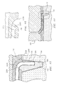
- the waxed/plugged RMC may then be secured to the feedcore, with the plug received in the compartment/slot 160 ( FIG. 11 ) of the feedcore.
- An exemplary securing comprises introducing a ceramic adhesive 170 between the plug and the slot.
- the ceramic adhesive 170 may also be such a slurry/slip.
- FIGS. 9 and 10 show the exemplary plug having faces 142 and 144 generally aligned with the faces 42 and 44 along the portion 70. These, however, may be provided with a slight taper toward an end face/facet 148.
- An exemplary taper angle ⁇ is less than 30° or less than 20° (e.g., 5 - 10° (e.g., about 6° with about 3° between each face of the plug and the adjacent face of the RMC)).
- FIG. 10 also shows lateral edges 145 and 146 of the plug with a width W therebetween.
- a thickness between the faces 142 and 144 is shown as T.
- a height of the plug is shown as H.
- FIGS. 11 and 12 similarly show the compartment 160 as having faces complementary to and dimensioned for receiving the plug.
- T is 1.0 - 5.0 mm at the thickest portion of the plug, more particularly, 1.5 - 3.0 mm or about 1.8 mm. Exemplary such T may be 2 to 10 times the thickness of the RMC, more narrowly, 3 to 5. Exemplary T is 0.75 - 4.0 mm at the narrowest portion of the plug (e.g., the facet 148), more particularly, 1.0 - 2.0 mm.
- Exemplary T at the narrowest portion of the plug may be slightly greater than the RMC thickness (e.g., 0 - 0.5 mm greater or, more narrowly 0.05 - 0.1 mm or 0.06 - 0.07 mm).
- Exemplary spacing of the face/facet 148 away from the adjacent edge of the RMC is 0 - 1 mm, more narrowly 0.3 - 0.5 mm or 0.35 - 0.40 mm.
- Exemplary W is at least 20 mm, more narrowly, 20 - 200 mm.
- Exemplary H is 2 - 10 mm, more narrowly, 3 - 6 mm.
- the resulting core assembly may then be transferred to a pattern forming die 180.
- the pattern forming die defines a compartment containing the core assembly into which a pattern forming material 190 is injected.
- the exemplary pattern forming material may similarly be a natural or synthetic wax.
- the overmoulded core assembly (or group of assemblies) forms a casting pattern with an exterior shape largely corresponding to the exterior shape of the part to be cast.
- the pattern may then be assembled to a shelling fixture (not shown, e.g., via wax welding between end plates of the fixture).
- the pattern may then be shelled (e.g., via one or more stages of slurry dipping, slurry spraying, or the like).
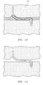
- the shell 200 FIG. 13
- it may be dried. The drying provides the shell with at least sufficient strength or other physical integrity properties to permit subsequent processing.
- the shell containing the invested core assembly may be disassembled fully or partially from the shelling fixture and then transferred to a dewaxer (e.g., a steam autoclave).
- a dewaxer e.g., a steam autoclave
- a steam dewax process removes a major portion of the wax leaving the core assembly secured within the shell ( FIG. 14 ).
- the shell and core assembly will largely form the ultimate mould.
- the dewax process typically leaves a residue on the shell interior and core assembly.
- the shell may be transferred to a furnace (e.g., containing air or other oxidizing atmosphere) in which it is heated to strengthen the shell and remove any remaining wax residue (e.g., by vaporization) and/or converting hydrocarbon residue to carbon.
- Oxygen in the atmosphere reacts with the carbon to form carbon dioxide. Removal of the carbon is advantageous to reduce or eliminate the formation of detrimental carbides in the metal casting. Removing carbon offers the additional advantage of reducing the potential for clogging the vacuum pumps used in subsequent stages of operation.
- the mould may be removed from the atmospheric furnace, allowed to cool, and inspected.
- the mould may be seeded by placing a metallic seed in the mould to establish the ultimate crystal structure of a directionally solidified (DS) casting or a single-crystal (SX) casting. Nevertheless the present teachings may be applied to other DS and SX casting techniques (e.g., wherein the shell geometry defines a grain selector) or to casting of other microstructures.
- the mould may be transferred to a casting furnace (e.g., placed atop a chill plate (not shown) in the furnace).
- the casting furnace may be pumped down to vacuum or charged with a non-oxidizing atmosphere (e.g., inert gas) to prevent oxidation of the casting alloy.
- the casting furnace is heated to preheat the mould. This preheating serves two purposes: to further harden and strengthen the shell; and to preheat the shell for the introduction of molten alloy to prevent thermal shock and premature solidification of the alloy.
- the molten alloy may be poured into the mould and the mould is allowed to cool to solidify the alloy (e.g., after withdrawal from the furnace hot zone). After solidification, the vacuum may be broken and the chilled mould removed from the casting furnace. The shell may be removed in a deshelling process (e.g., mechanical breaking of the shell).
- the core assembly is removed in a decoring process such as alkaline and/or acid leaching (e.g., to leave a cast article (e.g., a metallic precursor of the ultimate part)).
- a cast article e.g., a metallic precursor of the ultimate part
- the cast article may be machined, chemically and/or thermally treated and coated to form the ultimate part. Some or all of any machining or chemical or thermal treatment may be performed before the decoring.
- the moulding of the mask to the RMC may create the bulges 110 ( FIG. 5 ) which form negative lead ins 220A, 220B ( FIG. 12 ) from the wax to the RMC.
- FIG. 12 shows the wax material protruding away from the location of initial contact with the RMC with a convexly rounded cross section at junctions of the inboard face (adjacent the RMC) of the wax layer.
- a junction of the outboard face of the wax layer with the leading edge of such layer may have a convex cross section.
- the plug material will fill the gap provided by the negative lead in and thereby provide a positive lead in 222A, 222B of the plug relative to the RMC.
- FIG. 12 also shows the protective coating layer (e.g., aluminide) atop the RMC.
- the protective coating layer e.g., aluminide
- a first alternate process may be otherwise similar to the process described above. This process, however, forms the plug via materials and techniques more traditionally used to form ceramic cores such as the feedcore.
- the masked RMC may be formed by the process described above.
- the cold plug forming die may be inappropriate for the modified technique (e.g., a different die technology may be used).
- the masked/plugged RMC is baked to harden the plug. This baking melts the wax.
- one or more wax sheets 300A, 300B may be placed along the faces of the RMC. Although there may be a cold moulding process, this has less relevance than in the initial masking situation.
- the plugged core and positioning wax may be assembled and secured to the feedcore as described above. Thereafter, placement in the pattern forming die and subsequent steps may be similarly performed to those described above.
- Yet a further variation replaces the wax sheet in the core positioning stage with conventional chaplets 350A, 350B on either side of the RMC.
- the masked/plugged RMC (with a green plug) may be mated to the feedcore with the feedcore also in a green state.
- the assembly may then be baked.
- the baking may join/fuse the plug and feedcore.
- the plug may be held in the socket of the feedcore with sufficient pressure to assist fusing.
- a ceramic slip or slurry may be added at the interface/junction.
- the baking may melt away the masking material.
- the chaplets 350A and 350B (or other shim) may then be applied. This may involve sliding or rolling the chaplets 350A between the RMC and feedcore. Thereafter, placement in the pattern forming die and subsequent process steps may be otherwise similar to those described above.
Landscapes
- Engineering & Computer Science (AREA)
- Mechanical Engineering (AREA)
- Molds, Cores, And Manufacturing Methods Thereof (AREA)
Applications Claiming Priority (1)
| Application Number | Priority Date | Filing Date | Title |
|---|---|---|---|
| US12/981,650 US8251123B2 (en) | 2010-12-30 | 2010-12-30 | Casting core assembly methods |
Publications (2)
| Publication Number | Publication Date |
|---|---|
| EP2471613A2 true EP2471613A2 (fr) | 2012-07-04 |
| EP2471613A3 EP2471613A3 (fr) | 2014-05-21 |
Family
ID=45463348
Family Applications (1)
| Application Number | Title | Priority Date | Filing Date |
|---|---|---|---|
| EP11195322.0A Withdrawn EP2471613A3 (fr) | 2010-12-30 | 2011-12-22 | Assemblage de noyau de moulage et procédé de fabrication |
Country Status (2)
| Country | Link |
|---|---|
| US (1) | US8251123B2 (fr) |
| EP (1) | EP2471613A3 (fr) |
Cited By (2)
| Publication number | Priority date | Publication date | Assignee | Title |
|---|---|---|---|---|
| EP2913121A1 (fr) * | 2014-02-28 | 2015-09-02 | United Technologies Corporation | Ensemble de noyau comprenant une entretoise à ergots |
| EP2892671A4 (fr) * | 2012-09-10 | 2016-05-18 | United Technologies Corp | Ensemble coeur métallique réfractaire et céramique |
Families Citing this family (24)
| Publication number | Priority date | Publication date | Assignee | Title |
|---|---|---|---|---|
| US9950382B2 (en) * | 2012-03-23 | 2018-04-24 | Pratt & Whitney Canada Corp. | Method for a fabricated heat shield with rails and studs mounted on the cold side of a combustor heat shield |
| US20140102656A1 (en) * | 2012-10-12 | 2014-04-17 | United Technologies Corporation | Casting Cores and Manufacture Methods |
| US9987679B2 (en) | 2013-10-07 | 2018-06-05 | United Technologies Corporation | Rapid tooling insert manufacture |
| EP3060363B1 (fr) | 2013-10-24 | 2021-10-27 | Raytheon Technologies Corporation | Moulage à noyau perdu pour former des passages de refroidissement |
| WO2015073202A1 (fr) * | 2013-11-18 | 2015-05-21 | United Technologies Corporation | Noyaux de coulée enduits et procédés de fabrication associés |
| US10370980B2 (en) * | 2013-12-23 | 2019-08-06 | United Technologies Corporation | Lost core structural frame |
| WO2016166623A1 (fr) * | 2015-04-17 | 2016-10-20 | Cannabix Technologies Inc. | Dispositif de détection de cannabis |
| US9579714B1 (en) | 2015-12-17 | 2017-02-28 | General Electric Company | Method and assembly for forming components having internal passages using a lattice structure |
| US10046389B2 (en) | 2015-12-17 | 2018-08-14 | General Electric Company | Method and assembly for forming components having internal passages using a jacketed core |
| US10137499B2 (en) | 2015-12-17 | 2018-11-27 | General Electric Company | Method and assembly for forming components having an internal passage defined therein |
| US10099283B2 (en) | 2015-12-17 | 2018-10-16 | General Electric Company | Method and assembly for forming components having an internal passage defined therein |
| US9987677B2 (en) | 2015-12-17 | 2018-06-05 | General Electric Company | Method and assembly for forming components having internal passages using a jacketed core |
| US10118217B2 (en) | 2015-12-17 | 2018-11-06 | General Electric Company | Method and assembly for forming components having internal passages using a jacketed core |
| US10150158B2 (en) * | 2015-12-17 | 2018-12-11 | General Electric Company | Method and assembly for forming components having internal passages using a jacketed core |
| US10099276B2 (en) | 2015-12-17 | 2018-10-16 | General Electric Company | Method and assembly for forming components having an internal passage defined therein |
| US9968991B2 (en) | 2015-12-17 | 2018-05-15 | General Electric Company | Method and assembly for forming components having internal passages using a lattice structure |
| US10099284B2 (en) | 2015-12-17 | 2018-10-16 | General Electric Company | Method and assembly for forming components having a catalyzed internal passage defined therein |
| US10286450B2 (en) | 2016-04-27 | 2019-05-14 | General Electric Company | Method and assembly for forming components using a jacketed core |
| US10335853B2 (en) * | 2016-04-27 | 2019-07-02 | General Electric Company | Method and assembly for forming components using a jacketed core |
| US10315248B2 (en) * | 2016-11-17 | 2019-06-11 | General Electric Company | Methods and apparatuses using cast in core reference features |
| US11806894B2 (en) * | 2018-12-21 | 2023-11-07 | Chromalloy Gas Turbine Llc | Method and apparatus for improving core manufacturing for gas turbine components |
| US11179769B2 (en) * | 2019-02-08 | 2021-11-23 | Raytheon Technologies Corporation | Investment casting pin and method of using same |
| US11642720B2 (en) * | 2019-10-16 | 2023-05-09 | Raytheon Technologies Corporation | Integral core bumpers |
| US11998974B2 (en) * | 2022-08-30 | 2024-06-04 | General Electric Company | Casting core for a cast engine component |
Citations (5)
| Publication number | Priority date | Publication date | Assignee | Title |
|---|---|---|---|---|
| US6637500B2 (en) | 2001-10-24 | 2003-10-28 | United Technologies Corporation | Cores for use in precision investment casting |
| US6929054B2 (en) | 2003-12-19 | 2005-08-16 | United Technologies Corporation | Investment casting cores |
| US7014424B2 (en) | 2003-04-08 | 2006-03-21 | United Technologies Corporation | Turbine element |
| US20060239819A1 (en) | 2005-04-22 | 2006-10-26 | United Technologies Corporation | Airfoil trailing edge cooling |
| US7134475B2 (en) | 2004-10-29 | 2006-11-14 | United Technologies Corporation | Investment casting cores and methods |
Family Cites Families (6)
| Publication number | Priority date | Publication date | Assignee | Title |
|---|---|---|---|---|
| US5394932A (en) | 1992-01-17 | 1995-03-07 | Howmet Corporation | Multiple part cores for investment casting |
| US20050087319A1 (en) | 2003-10-16 | 2005-04-28 | Beals James T. | Refractory metal core wall thickness control |
| US7216689B2 (en) * | 2004-06-14 | 2007-05-15 | United Technologies Corporation | Investment casting |
| US7303375B2 (en) * | 2005-11-23 | 2007-12-04 | United Technologies Corporation | Refractory metal core cooling technologies for curved leading edge slots |
| US20090000754A1 (en) * | 2007-06-27 | 2009-01-01 | United Technologies Corporation | Investment casting cores and methods |
| US8100165B2 (en) | 2008-11-17 | 2012-01-24 | United Technologies Corporation | Investment casting cores and methods |
-
2010
- 2010-12-30 US US12/981,650 patent/US8251123B2/en active Active
-
2011
- 2011-12-22 EP EP11195322.0A patent/EP2471613A3/fr not_active Withdrawn
Patent Citations (5)
| Publication number | Priority date | Publication date | Assignee | Title |
|---|---|---|---|---|
| US6637500B2 (en) | 2001-10-24 | 2003-10-28 | United Technologies Corporation | Cores for use in precision investment casting |
| US7014424B2 (en) | 2003-04-08 | 2006-03-21 | United Technologies Corporation | Turbine element |
| US6929054B2 (en) | 2003-12-19 | 2005-08-16 | United Technologies Corporation | Investment casting cores |
| US7134475B2 (en) | 2004-10-29 | 2006-11-14 | United Technologies Corporation | Investment casting cores and methods |
| US20060239819A1 (en) | 2005-04-22 | 2006-10-26 | United Technologies Corporation | Airfoil trailing edge cooling |
Cited By (8)
| Publication number | Priority date | Publication date | Assignee | Title |
|---|---|---|---|---|
| EP2892671A4 (fr) * | 2012-09-10 | 2016-05-18 | United Technologies Corp | Ensemble coeur métallique réfractaire et céramique |
| US9486854B2 (en) | 2012-09-10 | 2016-11-08 | United Technologies Corporation | Ceramic and refractory metal core assembly |
| US10252328B2 (en) | 2012-09-10 | 2019-04-09 | United Technologies Corporation | Ceramic and refractory metal core assembly |
| EP2913121A1 (fr) * | 2014-02-28 | 2015-09-02 | United Technologies Corporation | Ensemble de noyau comprenant une entretoise à ergots |
| EP3090820A1 (fr) * | 2014-02-28 | 2016-11-09 | United Technologies Corporation | Ensemble de noyau comprenant une entretoise à ergots |
| EP2913121B1 (fr) | 2014-02-28 | 2017-04-05 | United Technologies Corporation | Ensemble de noyau comprenant une entretoise à ergots |
| US10300526B2 (en) | 2014-02-28 | 2019-05-28 | United Technologies Corporation | Core assembly including studded spacer |
| EP3821996A1 (fr) * | 2014-02-28 | 2021-05-19 | Raytheon Technologies Corporation | Ensemble de noyau comprenant une entretoise à ergots |
Also Published As
| Publication number | Publication date |
|---|---|
| US20120168108A1 (en) | 2012-07-05 |
| US8251123B2 (en) | 2012-08-28 |
| EP2471613A3 (fr) | 2014-05-21 |
Similar Documents
| Publication | Publication Date | Title |
|---|---|---|
| US8251123B2 (en) | Casting core assembly methods | |
| EP2511024B1 (fr) | Noyau de coulée métallique profilé | |
| EP1914030B1 (fr) | Noyeaux pour la coulée en cire perdue et leurs utilisation en fonderie en cire perdue | |
| US8100165B2 (en) | Investment casting cores and methods | |
| EP2189230B1 (fr) | Moulages, noyaux de moulage et procédés | |
| EP1992431B1 (fr) | Noyaux de moulage par coulée et procédés | |
| EP2191910B1 (fr) | Moulages, noyaux de moulage et procédés | |
| EP1857199B1 (fr) | Conception d'ensemble de noyau de coulée | |
| US9421606B2 (en) | Casting cores and manufacture methods | |
| EP2193859A1 (fr) | Moulages, noyaux de moulage et procédés | |
| US10821501B2 (en) | Coated casting core and manufacture methods | |
| US20110315336A1 (en) | Contoured Metallic Casting Core |
Legal Events
| Date | Code | Title | Description |
|---|---|---|---|
| AK | Designated contracting states |
Kind code of ref document: A2 Designated state(s): AL AT BE BG CH CY CZ DE DK EE ES FI FR GB GR HR HU IE IS IT LI LT LU LV MC MK MT NL NO PL PT RO RS SE SI SK SM TR |
|
| AX | Request for extension of the european patent |
Extension state: BA ME |
|
| PUAI | Public reference made under article 153(3) epc to a published international application that has entered the european phase |
Free format text: ORIGINAL CODE: 0009012 |
|
| PUAL | Search report despatched |
Free format text: ORIGINAL CODE: 0009013 |
|
| AK | Designated contracting states |
Kind code of ref document: A3 Designated state(s): AL AT BE BG CH CY CZ DE DK EE ES FI FR GB GR HR HU IE IS IT LI LT LU LV MC MK MT NL NO PL PT RO RS SE SI SK SM TR |
|
| AX | Request for extension of the european patent |
Extension state: BA ME |
|
| RIC1 | Information provided on ipc code assigned before grant |
Ipc: B22C 9/10 20060101AFI20140414BHEP |
|
| STAA | Information on the status of an ep patent application or granted ep patent |
Free format text: STATUS: THE APPLICATION IS DEEMED TO BE WITHDRAWN |
|
| 18D | Application deemed to be withdrawn |
Effective date: 20140701 |