EP2471340B1 - Electrically heated window - Google Patents
Electrically heated window Download PDFInfo
- Publication number
- EP2471340B1 EP2471340B1 EP10737621.2A EP10737621A EP2471340B1 EP 2471340 B1 EP2471340 B1 EP 2471340B1 EP 10737621 A EP10737621 A EP 10737621A EP 2471340 B1 EP2471340 B1 EP 2471340B1
- Authority
- EP
- European Patent Office
- Prior art keywords
- grid
- window
- electrically heated
- heated window
- pathways
- Prior art date
- Legal status (The legal status is an assumption and is not a legal conclusion. Google has not performed a legal analysis and makes no representation as to the accuracy of the status listed.)
- Active
Links
- 230000037361 pathway Effects 0.000 claims description 77
- 239000000463 material Substances 0.000 claims description 22
- BQCADISMDOOEFD-UHFFFAOYSA-N Silver Chemical compound [Ag] BQCADISMDOOEFD-UHFFFAOYSA-N 0.000 claims description 15
- 229910052709 silver Inorganic materials 0.000 claims description 15
- 239000004332 silver Substances 0.000 claims description 15
- 239000011248 coating agent Substances 0.000 claims description 13
- 238000000576 coating method Methods 0.000 claims description 13
- 239000011229 interlayer Substances 0.000 claims description 11
- RYGMFSIKBFXOCR-UHFFFAOYSA-N Copper Chemical compound [Cu] RYGMFSIKBFXOCR-UHFFFAOYSA-N 0.000 claims description 7
- 229910052802 copper Inorganic materials 0.000 claims description 7
- 239000010949 copper Substances 0.000 claims description 7
- PXHVJJICTQNCMI-UHFFFAOYSA-N Nickel Chemical compound [Ni] PXHVJJICTQNCMI-UHFFFAOYSA-N 0.000 claims description 6
- 239000004020 conductor Substances 0.000 claims description 3
- 229910052759 nickel Inorganic materials 0.000 claims description 3
- 239000004411 aluminium Substances 0.000 claims description 2
- 229910052782 aluminium Inorganic materials 0.000 claims description 2
- XAGFODPZIPBFFR-UHFFFAOYSA-N aluminium Chemical compound [Al] XAGFODPZIPBFFR-UHFFFAOYSA-N 0.000 claims description 2
- PCHJSUWPFVWCPO-UHFFFAOYSA-N gold Chemical compound [Au] PCHJSUWPFVWCPO-UHFFFAOYSA-N 0.000 claims description 2
- 229910052737 gold Inorganic materials 0.000 claims description 2
- 239000010931 gold Substances 0.000 claims description 2
- 230000003137 locomotive effect Effects 0.000 claims description 2
- 229920002799 BoPET Polymers 0.000 description 12
- -1 polyethylene terephthalate Polymers 0.000 description 8
- 230000005540 biological transmission Effects 0.000 description 7
- 229910000679 solder Inorganic materials 0.000 description 7
- 238000010438 heat treatment Methods 0.000 description 6
- 229920002037 poly(vinyl butyral) polymer Polymers 0.000 description 6
- WFKWXMTUELFFGS-UHFFFAOYSA-N tungsten Chemical compound [W] WFKWXMTUELFFGS-UHFFFAOYSA-N 0.000 description 6
- 239000011521 glass Substances 0.000 description 5
- 229920000139 polyethylene terephthalate Polymers 0.000 description 5
- 239000005020 polyethylene terephthalate Substances 0.000 description 5
- 239000000853 adhesive Substances 0.000 description 4
- 230000001070 adhesive effect Effects 0.000 description 4
- 230000009286 beneficial effect Effects 0.000 description 4
- 238000012217 deletion Methods 0.000 description 4
- 230000037430 deletion Effects 0.000 description 4
- 238000000034 method Methods 0.000 description 4
- 229920006254 polymer film Polymers 0.000 description 4
- 229910052721 tungsten Inorganic materials 0.000 description 4
- 239000010937 tungsten Substances 0.000 description 4
- 238000005299 abrasion Methods 0.000 description 3
- 238000010030 laminating Methods 0.000 description 3
- 238000003475 lamination Methods 0.000 description 3
- BPQQTUXANYXVAA-UHFFFAOYSA-N Orthosilicate Chemical compound [O-][Si]([O-])([O-])[O-] BPQQTUXANYXVAA-UHFFFAOYSA-N 0.000 description 2
- 229930040373 Paraformaldehyde Natural products 0.000 description 2
- 239000004952 Polyamide Substances 0.000 description 2
- 239000004698 Polyethylene Substances 0.000 description 2
- 239000004642 Polyimide Substances 0.000 description 2
- 239000004743 Polypropylene Substances 0.000 description 2
- 239000000919 ceramic Substances 0.000 description 2
- 229920003020 cross-linked polyethylene Polymers 0.000 description 2
- 239000004703 cross-linked polyethylene Substances 0.000 description 2
- 230000001419 dependent effect Effects 0.000 description 2
- 239000005038 ethylene vinyl acetate Substances 0.000 description 2
- 239000005329 float glass Substances 0.000 description 2
- 239000011888 foil Substances 0.000 description 2
- 238000010348 incorporation Methods 0.000 description 2
- 238000004519 manufacturing process Methods 0.000 description 2
- 229920003023 plastic Polymers 0.000 description 2
- 239000004033 plastic Substances 0.000 description 2
- 229920003229 poly(methyl methacrylate) Polymers 0.000 description 2
- 229920002647 polyamide Polymers 0.000 description 2
- 229920001748 polybutylene Polymers 0.000 description 2
- 229920001707 polybutylene terephthalate Polymers 0.000 description 2
- 239000004417 polycarbonate Substances 0.000 description 2
- 229920000515 polycarbonate Polymers 0.000 description 2
- 229920000728 polyester Polymers 0.000 description 2
- 229920000573 polyethylene Polymers 0.000 description 2
- 229920001721 polyimide Polymers 0.000 description 2
- 239000004926 polymethyl methacrylate Substances 0.000 description 2
- 229920006324 polyoxymethylene Polymers 0.000 description 2
- 229920013636 polyphenyl ether polymer Polymers 0.000 description 2
- 229920001155 polypropylene Polymers 0.000 description 2
- 239000004810 polytetrafluoroethylene Substances 0.000 description 2
- 229920001343 polytetrafluoroethylene Polymers 0.000 description 2
- 238000000926 separation method Methods 0.000 description 2
- 238000010257 thawing Methods 0.000 description 2
- PYSRRFNXTXNWCD-UHFFFAOYSA-N 3-(2-phenylethenyl)furan-2,5-dione Chemical compound O=C1OC(=O)C(C=CC=2C=CC=CC=2)=C1 PYSRRFNXTXNWCD-UHFFFAOYSA-N 0.000 description 1
- 239000004793 Polystyrene Substances 0.000 description 1
- 229920000147 Styrene maleic anhydride Polymers 0.000 description 1
- 208000027418 Wounds and injury Diseases 0.000 description 1
- 239000004676 acrylonitrile butadiene styrene Substances 0.000 description 1
- 238000004026 adhesive bonding Methods 0.000 description 1
- 229910045601 alloy Inorganic materials 0.000 description 1
- 239000000956 alloy Substances 0.000 description 1
- 230000015572 biosynthetic process Effects 0.000 description 1
- 230000015556 catabolic process Effects 0.000 description 1
- 238000002788 crimping Methods 0.000 description 1
- 230000006378 damage Effects 0.000 description 1
- 238000006731 degradation reaction Methods 0.000 description 1
- 238000013461 design Methods 0.000 description 1
- 230000000694 effects Effects 0.000 description 1
- 230000004907 flux Effects 0.000 description 1
- 208000014674 injury Diseases 0.000 description 1
- 238000002844 melting Methods 0.000 description 1
- 230000008018 melting Effects 0.000 description 1
- 229910052751 metal Inorganic materials 0.000 description 1
- 239000002184 metal Substances 0.000 description 1
- 150000002739 metals Chemical class 0.000 description 1
- 239000003595 mist Substances 0.000 description 1
- 238000012986 modification Methods 0.000 description 1
- 230000004048 modification Effects 0.000 description 1
- 230000003287 optical effect Effects 0.000 description 1
- 229920002492 poly(sulfone) Polymers 0.000 description 1
- 239000004626 polylactic acid Substances 0.000 description 1
- 239000004814 polyurethane Substances 0.000 description 1
- 239000004800 polyvinyl chloride Substances 0.000 description 1
- 239000005033 polyvinylidene chloride Substances 0.000 description 1
- 238000005476 soldering Methods 0.000 description 1
- 239000011145 styrene acrylonitrile resin Substances 0.000 description 1
- 239000000126 substance Substances 0.000 description 1
- 239000000758 substrate Substances 0.000 description 1
Images


Classifications
-
- H—ELECTRICITY
- H05—ELECTRIC TECHNIQUES NOT OTHERWISE PROVIDED FOR
- H05B—ELECTRIC HEATING; ELECTRIC LIGHT SOURCES NOT OTHERWISE PROVIDED FOR; CIRCUIT ARRANGEMENTS FOR ELECTRIC LIGHT SOURCES, IN GENERAL
- H05B3/00—Ohmic-resistance heating
- H05B3/84—Heating arrangements specially adapted for transparent or reflecting areas, e.g. for demisting or de-icing windows, mirrors or vehicle windshields
- H05B3/86—Heating arrangements specially adapted for transparent or reflecting areas, e.g. for demisting or de-icing windows, mirrors or vehicle windshields the heating conductors being embedded in the transparent or reflecting material
-
- H—ELECTRICITY
- H05—ELECTRIC TECHNIQUES NOT OTHERWISE PROVIDED FOR
- H05B—ELECTRIC HEATING; ELECTRIC LIGHT SOURCES NOT OTHERWISE PROVIDED FOR; CIRCUIT ARRANGEMENTS FOR ELECTRIC LIGHT SOURCES, IN GENERAL
- H05B3/00—Ohmic-resistance heating
- H05B3/84—Heating arrangements specially adapted for transparent or reflecting areas, e.g. for demisting or de-icing windows, mirrors or vehicle windshields
-
- B—PERFORMING OPERATIONS; TRANSPORTING
- B32—LAYERED PRODUCTS
- B32B—LAYERED PRODUCTS, i.e. PRODUCTS BUILT-UP OF STRATA OF FLAT OR NON-FLAT, e.g. CELLULAR OR HONEYCOMB, FORM
- B32B17/00—Layered products essentially comprising sheet glass, or glass, slag, or like fibres
- B32B17/06—Layered products essentially comprising sheet glass, or glass, slag, or like fibres comprising glass as the main or only constituent of a layer, next to another layer of a specific material
- B32B17/10—Layered products essentially comprising sheet glass, or glass, slag, or like fibres comprising glass as the main or only constituent of a layer, next to another layer of a specific material of synthetic resin
- B32B17/10005—Layered products essentially comprising sheet glass, or glass, slag, or like fibres comprising glass as the main or only constituent of a layer, next to another layer of a specific material of synthetic resin laminated safety glass or glazing
- B32B17/10009—Layered products essentially comprising sheet glass, or glass, slag, or like fibres comprising glass as the main or only constituent of a layer, next to another layer of a specific material of synthetic resin laminated safety glass or glazing characterized by the number, the constitution or treatment of glass sheets
- B32B17/10036—Layered products essentially comprising sheet glass, or glass, slag, or like fibres comprising glass as the main or only constituent of a layer, next to another layer of a specific material of synthetic resin laminated safety glass or glazing characterized by the number, the constitution or treatment of glass sheets comprising two outer glass sheets
-
- B—PERFORMING OPERATIONS; TRANSPORTING
- B32—LAYERED PRODUCTS
- B32B—LAYERED PRODUCTS, i.e. PRODUCTS BUILT-UP OF STRATA OF FLAT OR NON-FLAT, e.g. CELLULAR OR HONEYCOMB, FORM
- B32B17/00—Layered products essentially comprising sheet glass, or glass, slag, or like fibres
- B32B17/06—Layered products essentially comprising sheet glass, or glass, slag, or like fibres comprising glass as the main or only constituent of a layer, next to another layer of a specific material
- B32B17/10—Layered products essentially comprising sheet glass, or glass, slag, or like fibres comprising glass as the main or only constituent of a layer, next to another layer of a specific material of synthetic resin
- B32B17/10005—Layered products essentially comprising sheet glass, or glass, slag, or like fibres comprising glass as the main or only constituent of a layer, next to another layer of a specific material of synthetic resin laminated safety glass or glazing
- B32B17/10165—Functional features of the laminated safety glass or glazing
- B32B17/10293—Edge features, e.g. inserts or holes
-
- B—PERFORMING OPERATIONS; TRANSPORTING
- B32—LAYERED PRODUCTS
- B32B—LAYERED PRODUCTS, i.e. PRODUCTS BUILT-UP OF STRATA OF FLAT OR NON-FLAT, e.g. CELLULAR OR HONEYCOMB, FORM
- B32B17/00—Layered products essentially comprising sheet glass, or glass, slag, or like fibres
- B32B17/06—Layered products essentially comprising sheet glass, or glass, slag, or like fibres comprising glass as the main or only constituent of a layer, next to another layer of a specific material
- B32B17/10—Layered products essentially comprising sheet glass, or glass, slag, or like fibres comprising glass as the main or only constituent of a layer, next to another layer of a specific material of synthetic resin
- B32B17/10005—Layered products essentially comprising sheet glass, or glass, slag, or like fibres comprising glass as the main or only constituent of a layer, next to another layer of a specific material of synthetic resin laminated safety glass or glazing
- B32B17/10165—Functional features of the laminated safety glass or glazing
- B32B17/10339—Specific parts of the laminated safety glass or glazing being colored or tinted
- B32B17/10348—Specific parts of the laminated safety glass or glazing being colored or tinted comprising an obscuration band
-
- B—PERFORMING OPERATIONS; TRANSPORTING
- B32—LAYERED PRODUCTS
- B32B—LAYERED PRODUCTS, i.e. PRODUCTS BUILT-UP OF STRATA OF FLAT OR NON-FLAT, e.g. CELLULAR OR HONEYCOMB, FORM
- B32B17/00—Layered products essentially comprising sheet glass, or glass, slag, or like fibres
- B32B17/06—Layered products essentially comprising sheet glass, or glass, slag, or like fibres comprising glass as the main or only constituent of a layer, next to another layer of a specific material
- B32B17/10—Layered products essentially comprising sheet glass, or glass, slag, or like fibres comprising glass as the main or only constituent of a layer, next to another layer of a specific material of synthetic resin
- B32B17/10005—Layered products essentially comprising sheet glass, or glass, slag, or like fibres comprising glass as the main or only constituent of a layer, next to another layer of a specific material of synthetic resin laminated safety glass or glazing
- B32B17/1055—Layered products essentially comprising sheet glass, or glass, slag, or like fibres comprising glass as the main or only constituent of a layer, next to another layer of a specific material of synthetic resin laminated safety glass or glazing characterized by the resin layer, i.e. interlayer
- B32B17/10761—Layered products essentially comprising sheet glass, or glass, slag, or like fibres comprising glass as the main or only constituent of a layer, next to another layer of a specific material of synthetic resin laminated safety glass or glazing characterized by the resin layer, i.e. interlayer containing vinyl acetal
-
- H—ELECTRICITY
- H05—ELECTRIC TECHNIQUES NOT OTHERWISE PROVIDED FOR
- H05B—ELECTRIC HEATING; ELECTRIC LIGHT SOURCES NOT OTHERWISE PROVIDED FOR; CIRCUIT ARRANGEMENTS FOR ELECTRIC LIGHT SOURCES, IN GENERAL
- H05B3/00—Ohmic-resistance heating
- H05B3/10—Heating elements characterised by the composition or nature of the materials or by the arrangement of the conductor
- H05B3/12—Heating elements characterised by the composition or nature of the materials or by the arrangement of the conductor characterised by the composition or nature of the conductive material
-
- H—ELECTRICITY
- H05—ELECTRIC TECHNIQUES NOT OTHERWISE PROVIDED FOR
- H05B—ELECTRIC HEATING; ELECTRIC LIGHT SOURCES NOT OTHERWISE PROVIDED FOR; CIRCUIT ARRANGEMENTS FOR ELECTRIC LIGHT SOURCES, IN GENERAL
- H05B3/00—Ohmic-resistance heating
- H05B3/20—Heating elements having extended surface area substantially in a two-dimensional plane, e.g. plate-heater
- H05B3/22—Heating elements having extended surface area substantially in a two-dimensional plane, e.g. plate-heater non-flexible
- H05B3/26—Heating elements having extended surface area substantially in a two-dimensional plane, e.g. plate-heater non-flexible heating conductor mounted on insulating base
- H05B3/265—Heating elements having extended surface area substantially in a two-dimensional plane, e.g. plate-heater non-flexible heating conductor mounted on insulating base the insulating base being an inorganic material, e.g. ceramic
-
- H—ELECTRICITY
- H05—ELECTRIC TECHNIQUES NOT OTHERWISE PROVIDED FOR
- H05B—ELECTRIC HEATING; ELECTRIC LIGHT SOURCES NOT OTHERWISE PROVIDED FOR; CIRCUIT ARRANGEMENTS FOR ELECTRIC LIGHT SOURCES, IN GENERAL
- H05B2203/00—Aspects relating to Ohmic resistive heating covered by group H05B3/00
- H05B2203/002—Heaters using a particular layout for the resistive material or resistive elements
- H05B2203/007—Heaters using a particular layout for the resistive material or resistive elements using multiple electrically connected resistive elements or resistive zones
-
- H—ELECTRICITY
- H05—ELECTRIC TECHNIQUES NOT OTHERWISE PROVIDED FOR
- H05B—ELECTRIC HEATING; ELECTRIC LIGHT SOURCES NOT OTHERWISE PROVIDED FOR; CIRCUIT ARRANGEMENTS FOR ELECTRIC LIGHT SOURCES, IN GENERAL
- H05B2203/00—Aspects relating to Ohmic resistive heating covered by group H05B3/00
- H05B2203/011—Heaters using laterally extending conductive material as connecting means
-
- H—ELECTRICITY
- H05—ELECTRIC TECHNIQUES NOT OTHERWISE PROVIDED FOR
- H05B—ELECTRIC HEATING; ELECTRIC LIGHT SOURCES NOT OTHERWISE PROVIDED FOR; CIRCUIT ARRANGEMENTS FOR ELECTRIC LIGHT SOURCES, IN GENERAL
- H05B2203/00—Aspects relating to Ohmic resistive heating covered by group H05B3/00
- H05B2203/013—Heaters using resistive films or coatings
-
- H—ELECTRICITY
- H05—ELECTRIC TECHNIQUES NOT OTHERWISE PROVIDED FOR
- H05B—ELECTRIC HEATING; ELECTRIC LIGHT SOURCES NOT OTHERWISE PROVIDED FOR; CIRCUIT ARRANGEMENTS FOR ELECTRIC LIGHT SOURCES, IN GENERAL
- H05B2203/00—Aspects relating to Ohmic resistive heating covered by group H05B3/00
- H05B2203/017—Manufacturing methods or apparatus for heaters
-
- H—ELECTRICITY
- H05—ELECTRIC TECHNIQUES NOT OTHERWISE PROVIDED FOR
- H05B—ELECTRIC HEATING; ELECTRIC LIGHT SOURCES NOT OTHERWISE PROVIDED FOR; CIRCUIT ARRANGEMENTS FOR ELECTRIC LIGHT SOURCES, IN GENERAL
- H05B2203/00—Aspects relating to Ohmic resistive heating covered by group H05B3/00
- H05B2203/031—Heaters specially adapted for heating the windscreen wiper area
-
- Y—GENERAL TAGGING OF NEW TECHNOLOGICAL DEVELOPMENTS; GENERAL TAGGING OF CROSS-SECTIONAL TECHNOLOGIES SPANNING OVER SEVERAL SECTIONS OF THE IPC; TECHNICAL SUBJECTS COVERED BY FORMER USPC CROSS-REFERENCE ART COLLECTIONS [XRACs] AND DIGESTS
- Y10—TECHNICAL SUBJECTS COVERED BY FORMER USPC
- Y10T—TECHNICAL SUBJECTS COVERED BY FORMER US CLASSIFICATION
- Y10T29/00—Metal working
- Y10T29/49—Method of mechanical manufacture
- Y10T29/49002—Electrical device making
Definitions
- This invention relates to an electrically heated window, in particular, a laminated electrically heated window comprising a grid of at least one electrically conductive pathway attached to a film, its method of manufacture and its use.
- This invention also relates to a vehicle incorporating said electrically heated window.
- Electrically heated windows are commonly used as either windscreens or backlights in vehicles in order to be able to demist or defrost the window in cold and/or damp weather conditions.
- the electrical heating means are generally provided as an array of fine (having a diameter of less than 30 micrometres), closely spaced (a wire-to-wire distance of between 1mm and 3mm) wires.
- the wires in such an array are generally parallel, each is ordinarily provided with undulations, such as crimping in a sinusoidal, helical, zig zag or random pattern, to avoid dazzling and polarisation effects when objects are viewed through the window by a vehicle driver.
- Heating functionality has traditionally been provided by incorporating tungsten heating elements within a laminate, as described in EP 0 788 294 , or by the inclusion of a conducting coating (for example sputtered onto an internal glass surface, as described in WO 00/76930 , or on a separate plastic (PET) substrate).
- the tungsten wired product has the disadvantage of wire visibility which can be distracting to drivers of vehicles, especially if sections of a window, such as the sections of a windscreen adjacent the A-pillars of a car, do not comprise the tungsten wire, and therefore some original equipment manufacturers dislike the existing wired product.
- the coated heated product usually requires a supply voltage greater than the standard 12.0/13.0 Volts due to the sheet resistivity of the conducting coating (e.g. 42 Volts) to achieve a power density sufficient to defrost the windscreen.
- an electrically heated window comprising:
- grid means a framework of at least one crisscrossed or parallel electrically conductive pathways based on, for example, square, rectangular, triangular, hexagonal and/or diamond-shaped cells.
- the at least one pathways may be any suitable shape such as straight, curved or sinusoidal. This arrangement is advantageous because it enables the grid to more easily function coextensively with the plies of a glazing material.
- the shape of the window may not allow the same length of tungsten wire to be incorporated throughout the window, such as in the sections of a windscreen adjacent the A-pillars of a car.
- the presence of one or more hot spots in a window is highly undesirable for two reasons: firstly, there is a risk that the occupants of a vehicle in which such a window is fitted may touch the window in the region of the one or more hotspots, causing injury; and secondly, there is a risk of the window locally de-laminating in the region of the hot spots. This results in regions of the window having reduced or zero visibility.
- the grid is a framework of square or rectangular cells.
- the grid may be substantially coextensive within the two plies of a glazing material.
- the at least one electrically conductive pathway may be manufactured from a material selected typically from the group consisting of silver, copper, gold, or aluminium. Other metals of low resistivity typically less than 8 x 10 -8 may be suitable such that they can provide the necessary sheet resistance of 0.1 to 1.0 ohm-square whilst maintaining adequate visibility.
- the at least one electrically conductive pathway is silver.
- the film may be a polymer film.
- the polymer film may be selected from the group consisting of polyethylene terephthalate (PET), polyethylene (PE), cross-linked polyethylene (PEX), polyphenyl ether (PPE), polyvinyl chloride (PVC), polyvinylidene chloride (PVDC), polylactic acid (PLA), polypropylene (PP), polybutylene (PB), polybutylene terephthalate (PBT), polyamide (PA), polyimide (PI), polycarbonate (PC), polytetrafluoroethylene (PTFE), polystyrene (PS), polyurethane (PU), polyester (PEs), acrylonitrile butadiene styrene (ABS), polymethyl methacrylate (PMMA), polyoxymethylene (POM), polysulfone (PES), styrene-acrylonitrile (SAN), ethylene vinyl acetate (EVA), and styrene maleic anhydride film.
- PET
- the film may have a thickness of less than 200 micrometres, preferably less than 100 micrometres, more preferably less than 75 micrometres, even more preferably less than 50 micrometres, and most preferably less then 30 micrometres.
- a thinner film can be advantageous because the thicker the film is, the more likely it is that lamination into complex shapes will result in wrinkling of the film.
- the interlayer material may be selected from the group consisting of polyvinyl butyral (PVB), Ethylene-Vinyl Acetate (EVA) and other polymeric interlayers.
- PVB polyvinyl butyral
- EVA Ethylene-Vinyl Acetate
- the window may exhibit a light transmission of at least 70%, preferably at least 75%, such as for windscreens.
- the window may exhibit a light transmission of less than 75%, such as for bodyglass.
- the window may exhibit a haze of less than 7%, preferably less than 6%, more preferably less than 5%.
- the window may exhibit a resistance typically from 0.1 to 1.0 ohm/square. This is advantageous because the resistance can be fine tuned to meet a required power density (for de-mist or de-frost functionality) such as a 12.0 to 13.0 Voltage supply which is used in a number of vehicles.
- the electrical connection means may comprise at least two busbars.
- the at least two busbars may be laminated between the at least two plies of a glazing material.
- the electrical connection means may further comprise an electrical connector connected to at least one of the at least two busbars.
- the busbar incorporation may be achieved by gluing the busbar to one of the at least two plies of a glazing material.
- At least one of the busbars may be coated with a solder. It is advantageous to coat the busbars with a solder that will give a good electrical contact to the grid.
- the solder may be a silver-containing solder (with flux). Such a solder will give a good electrical interface to the grid.
- the solder may have a low melting point ( ⁇ 140°C) such that the solder flows to form a soldered joint during a lamination process (see EP 1 110 431 on secure busbars).
- At least one of the busbars may be crimped or have raised areas. This arrangement is beneficial because it gives an improved "pressure" contact point with the grid.
- At least one of the busbars may be coated with a conducting adhesive.
- a busbar can be "glued” onto the grid and film. This arrangement affords a good electrical contact and sufficient bond strength to keep the busbar in position on the grid and film during assembly of the window.
- At least one of the busbars may be a printed silver busbar which may be incorporated onto one of the at least two plies of a glazing material at an interior laminating surface to give a mechanical contact with the grid attached to the film upon assembly.
- the grid attached to the film further comprises a coating of at least one electrical conductor such as copper and/or nickel.
- a coating can be advantageous because it can improve the solar control properties of the window due to its reflective properties.
- At least one crimped busbar can be utilised to allow raised points on the at least one busbar to break through the coating during lamination. This arrangement improves the quality of the interface between the grid and the at least one busbar.
- Such a coating on the grid can be removed mechanically (using abrasion) or chemically. Removal of the coating improves the quality of the interface between the grid and the at least two busbars.
- the grid may have an increased surface area of the at least one electrically conductive pathway in a region adjacent at least one busbar. This arrangement improves the quality of the interface between the grid and the at least one busbar.
- the grid may have an increased thickness of at least one electrically conductive pathway in a region adjacent at least one busbar.
- thickness means the height of the at least one electrically conductive pathway from a connecting surface of the polymer film. This arrangement improves the quality of the interface between the grid and at least one busbar by improving solderability.
- the thickness of the at least one electrically conductive pathway in regions not adjacent the at least one busbar may be 2 to 30 micrometres, preferably 3 to 20 micrometres, more preferably 4 to 15 micrometres, even more preferably 5 to 13 micrometres, most preferably 6 to 12 micrometres.
- the thickness of at least one electrically conductive pathway in regions adjacent the at least one busbar may be at least 2 micrometres, preferably at least 10 micrometers, more preferably at least 20 micrometres, even more preferably at least 30 micrometres, even more preferably at least 40 micrometres.
- the at least one electrically conductive pathways may be arranged either in a first direction (“vertical” pathways) or in a second direction (“horizontal” pathways).
- the grid may comprise more vertical pathways than horizontal pathways.
- a grid arrangement with fewer pathways is advantageous because it increases the light transmission through the window. It is also advantageous to retain some horizontal pathways to act as an alternate current path should some of the vertical pathways become damaged.
- the distance between adjacent vertical and/or between adjacent horizontal pathways may be at least 100 micrometres, preferably at least 300 micrometres, more preferably at least 500 micrometres, even more preferably at least 1000 micrometres, even more preferably at least 1500 micrometres, most preferably at least 2000 micrometres.
- Increasing the distance between adjacent vertical and/or horizontal pathways increases the "open area" (i.e. the cross-sectional portions of the window that do not comprise electrically conductive pathways), allowing a greater light transmission.
- the width of the at least one electrically conductive pathways may be less than 50 micrometres, preferably less than 25 micrometres, even more preferably less than 17 micrometres, even more preferably less than 15 micrometres and most preferably less than 13 micrometres. It is beneficial for the width of the pathways to be smaller in order to improve the light transmission.
- the window may further comprise an additional film laminated between another two plies of a glazing material, wherein the additional film comprises a coating capable of at least partially reflecting light.
- a film can be beneficial because many windows, such as some automotive windows, require improved solar control performance to reduce undesirable heating of the interior of a vehicle.
- Said coating capable of at least partially reflecting light may be metallic.
- the film attached to a grid of at least one electrically conductive pathway may, on an opposing surface, further comprise a coating capable of at least partially reflecting light.
- a coating capable of at least partially reflecting light may be located on the same surface of the film that is attached to the grid.
- the grid may comprise one or more gaps in one or more of the electrically conductive pathways. Sections of the grid may be deleted by suitable methods such as mechanical abrasion, laser deletion and/or chemical deletion. Such modification of the grid design can be advantageous in order to allow, for example, for bespoke separate circuit functionality for wiper de-icers, heated camera windows, and to prevent electro magnetic inference for certain devices such as toll sensors and rain sensors. Alternatively the grid may be manufactured as new with sections deleted to avoid the need for a deletion process.
- the window may further comprise one or more of a wiper de-icer, a heated camera window, a toll sensor and rain sensor
- an electrically heated window comprising:
- an electrically heated window according to the invention in a vehicle, such as a car, van, truck, bus, coach, locomotive, aircraft, boat or ship.
- a vehicle incorporating at least one electrically heated window according to the invention.
- Figure 1 is a schematic plan view of a wire-heated window in accordance with the prior art.
- the wire-heated window 1 is generally trapezoidal in shape, and comprises an array of fine, closely-spaced wires 2, of which only a small proportion are shown for clarity.
- the array of wires 2 is bounded by a first electrical connection means or bus bar 3 and a second electrical connection means or bus bar 4.
- the wires within the array 2 extend between the first and second electrical connection means 3, 4.
- These electrical connection means 3, 4 connect the array to an electrical supply (not shown) by means of connectors 5, 6, 7, 8, which may be plug connectors or other connectors known within the art.
- a dotted line 9 represents the extent to which the periphery of the window is covered by an obscuration band.
- An obscuration band is usually provided by a printed, fired black ceramic ink positioned on an inner surface of the window.
- the function of the obscuration band is two-fold: firstly, aesthetic, as it acts to hide the edge of the window and cover the adhesive used to bond the window into a vehicle, as well as the frame surrounding the window aperture; and secondly, it prevents degradation of the adhesive used to bond the window into the vehicle due to exposure to UV rays in sunlight.
- a wire-free area 10 is represented by a hatched region, and in this example, is positioned adjacent the top edge of the window 1 (when fitted into a vehicle).
- a bus bar 3 is shaped so as to define the wire-free area to allow a data signal to be transmitted through the window to a device positioned in the vicinity of the wire-free area.
- the wire-free area 10 is concealed by the obscuration band.
- the window 1 is provided with an area 11 for affixing a mirror boss, and an area 12 for affixing a sensor, such as a light or moisture sensor.
- Figure 2 is a schematic cross-section of a side edge region of the wire heated window shown in Figure 1 .
- the window 1 comprises first 13 and second 14 plies of annealed silicate float glass having a ply of polyvinyl butyral interlayer material 15 extending and laminated therebetween.
- the obscuration band 16 is provided around the periphery of the window 1, obscuring one of the bus bars 3.
- the wires in the array 2 are parallel with the edge of the window 1.
- Figure 3 is a schematic plan view of the window in Figure 1 , showing bus bar separations. In Figure 3 , only the bus bars 3, 4 and the general shape of the window are shown for clarity.
- the bus bar 3 running along the top edge of the window 1, adjacent the wire-free region 10 is shaped to define the wire-free region, with several turns or corners. In this example, the bus bar 3 running along the top edge of the window 1 is in two portions, separated by a small break positioned on a line of approximate mirror symmetry vertically in the centre of the window 1.
- the spacing between the bus bar 3 running along the top edge of the window 1 and the bus bar 4 running along the bottom edge of the window in an edge region of the window 1 (which would be adjacent the "A" pillar when fitted in a vehicle) is represented by distance x.
- the spacing between the bus bar 3 running along the top edge of the window 1 and the bus bar 4 running along the bottom edge of the window in the centre, adjacent the wire-free area 10 is represented by spacing y.
- the spacing y at the centre of the window 1 is 10% larger than the spacing x at the edge of the window 1 adjacent the "A" pillar. This leads to a region having the same width as the wire-free area having an increased temperature in comparison with the remainder of the window due to the decrease in resistance and consequential increase in current carried in the shorter wires.
- the wire-free area may be up to 300mm in width, this hot spot region may also be at least 300mm in width.
- FIG. 4 shows a schematic cross section of an electrically heated window 20 in accordance with an embodiment of the present invention.
- This embodiment solves the problem of hot spots by utilising a silver grid 21 which prevents variation in the resistance of individual pathways, minimising the occurrence of hot spots.
- the silver grid effectively acts as a conductive sheet in which the current does not necessarily flow perpendicular to the busbars.
- the grid can be modified (by deleting small sections manually by abrasion, laser deletion etc) to prevent localised hot spot formation.
- the window 20 is generally trapezoidal in shape (not shown) having two opposing long edges and two opposing shorter edges.
- the grid 21 is attached to a PET film 22 and is connected to two tinned copper busbars 23, 24.
- the grid 21, PET film 22 and busbars 23, 24 are laminated between two plies of clear glass 25, 26 using a PVB interlayer 27.
- the busbars 23, 24 are attached directly to the PVB interlayer 27 to contact the grid 21, or can be connected directly to the grid itself (via soldering or a conducting adhesive).
- Figure 5 shows a schematic plan view of the electrically heated window 20 shown in Figure 4 .
- Figure 5 shows the generally trapezoidal shape of the window 20, along with a small proportion of the silver grid 21 for clarity.
- the pathways of the grid 21 have a thickness of 6 to 12 micrometres and a width of approximately 16 micrometres.
- the distance between adjacent vertical and/or adjacent horizontal pathways is 280 micrometres.
- the PET film 22 has a thickness of 100 micrometres.
- the busbars 23, 24 are 3 to 6mm in width and 0.03 to 0.08mm thick, with the tinned surface comprising either elemental Sn or an alloy having a Sn:Pb ratio of 60:40.
- the bus bars 23, 24 may be a single piece of foil, or may be formed of multiple pieces of foil, superimposed with the pathways of the grid 21 sandwiched partially in between.
- the ply of PVB interlayer material 27 is 0.76mm in thickness (two portions each of 0.38mm in thickness), and the plies of glass are in the range 1.2 to 3.0mm in thickness.
- the busbars 23, 24 connect the grid 21 to an electrical supply (not shown) by means of connectors which may be plug connectors or other connectors known within the art.
- An obscuration band may be provided by a printed, fired black ceramic ink positioned on an inner surface of the window.
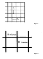
- Figure 6 shows a schematic plan view of a silver grid attached to a PET film, highlighting grid dimensions.
- the distance between adjacent vertical and between adjacent horizontal pathways is 280 micrometres.
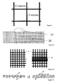
- Figures 7 and 8 each show a schematic plan view of a silver grid attached to a PET film where the grid pathway width is 16 micrometres and 12 micrometres respectively.
- Figure 9 shows a schematic view of a cross section of a pathway of a silver grid 21 attached to a PET film 22.
- the cross section of the pathway 21 is not symmetrical and, generally, the cross sectional shape of the pathways can be any suitable shape that allows current to flow through the pathways.
- Figure 10 shows a schematic plan view of an unmodified grid 21 (left) and a grid 21 with an increased pathway surface area in a particular region 28 (right).
- a grid 21 with an increased pathway surface area in a region adjacent a busbar improves the electrical and mechanical interface between the grid and the busbar.
- Figure 11 shows a schematic cross sectional view of the pathways of a grid attached to a PET film 22 with unmodified pathways 29 (left) and some pathways with increased thickness 30 (right).
- increasing the pathway thickness (the height above the surface of the PET) at a busbar interface area improves the interface between the grid and the busbar and improves solderability.
- Figure 12 shows a schematic plan view of, from the far left, an unmodified grid 31, a grid with reduced numbers of horizontal pathways 32, a grid with reduced pathway width 33 and a grid with reduced horizontal pathway width 34.
- reducing the number of individual pathways and/or the pathway width is beneficial because it improves the light transmission through the window.
- Figure 13 shows a schematic plan view of a grid 21 with gaps 35 in some of the pathways which is advantageous in some embodiments as it allows separate circuit functionality for heated camera windows, toll sensors etc.
- Figure 14 shows a schematic plan view of a grid 21 with gaps 36 in some of the pathways in order to allow for a heated wiper rest area circuit 37.
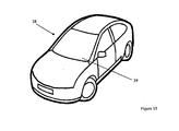
- FIG 15 shows a perspective view of a vehicle 38 according to an embodiment of the invention.
- the vehicle 38 incorporates an electrically heated window 39 according to the invention.
Landscapes
- Chemical & Material Sciences (AREA)
- Engineering & Computer Science (AREA)
- Ceramic Engineering (AREA)
- Surface Heating Bodies (AREA)
- Resistance Heating (AREA)
- Joining Of Glass To Other Materials (AREA)
- Laminated Bodies (AREA)
Description
- This invention relates to an electrically heated window, in particular, a laminated electrically heated window comprising a grid of at least one electrically conductive pathway attached to a film, its method of manufacture and its use. This invention also relates to a vehicle incorporating said electrically heated window.
- Electrically heated windows are commonly used as either windscreens or backlights in vehicles in order to be able to demist or defrost the window in cold and/or damp weather conditions. For windows used as a windscreen in a vehicle, the electrical heating means are generally provided as an array of fine (having a diameter of less than 30 micrometres), closely spaced (a wire-to-wire distance of between 1mm and 3mm) wires. Although the wires in such an array are generally parallel, each is ordinarily provided with undulations, such as crimping in a sinusoidal, helical, zig zag or random pattern, to avoid dazzling and polarisation effects when objects are viewed through the window by a vehicle driver.
- Heating functionality has traditionally been provided by incorporating tungsten heating elements within a laminate, as described in
EP 0 788 294 , or by the inclusion of a conducting coating (for example sputtered onto an internal glass surface, as described inWO 00/76930 - Consequently, there exists a need to provide electrically heated windows that improve on the visibility that is exhibited through the existing tungsten wired heated windows. It is also desirable to provide electrically heated windows that meet legal light transmission requirements, can be fine tuned to suit a particular power supply (nominally 12/13.0 Volts), provide a durable product (warranty performance), reduce undesirable heating of the interior of a vehicle (by providing solar control properties) and allow for the simple incorporation of devices such as wiper de-icers, heated camera windows and toll sensors.
- According to a first aspect of the present invention, there is provided an electrically heated window comprising:
- at least two plies of a glazing material;
- at least one ply of an interlayer material;
- a grid of at least one electrically conductive pathway attached to a film; and
- an electrical connection means for supplying current to the grid in order to heat the window;
- wherein the at least one ply of an interlayer material, the grid and the film are laminated between the at least two plies of a glazing material,
- wherein the grid further comprises a coating of at least one electrical conductor such as copper and/or nickel.
- It is to be understood that, in the context of this invention, "grid" means a framework of at least one crisscrossed or parallel electrically conductive pathways based on, for example, square, rectangular, triangular, hexagonal and/or diamond-shaped cells. The at least one pathways may be any suitable shape such as straight, curved or sinusoidal. This arrangement is advantageous because it enables the grid to more easily function coextensively with the plies of a glazing material. In an existing tungsten wired heated window, the shape of the window may not allow the same length of tungsten wire to be incorporated throughout the window, such as in the sections of a windscreen adjacent the A-pillars of a car. This can affect the local power density achieved due to differences between the resistances of wires with differing lengths. This creates regions of non-constant temperature, known as hot spots. The presence of one or more hot spots in a window is highly undesirable for two reasons: firstly, there is a risk that the occupants of a vehicle in which such a window is fitted may touch the window in the region of the one or more hotspots, causing injury; and secondly, there is a risk of the window locally de-laminating in the region of the hot spots. This results in regions of the window having reduced or zero visibility.
- The use of a grid solves this problem as it effectively forms a resistive sheet which allows current paths of approximate equal length to be achieved between the electrical connection means at for instance opposing edges of a windscreen.
- Preferably the grid is a framework of square or rectangular cells.
- The grid may be substantially coextensive within the two plies of a glazing material.
- The at least one electrically conductive pathway may be manufactured from a material selected typically from the group consisting of silver, copper, gold, or aluminium. Other metals of low resistivity typically less than 8 x 10⁻⁸ may be suitable such that they can provide the necessary sheet resistance of 0.1 to 1.0 ohm-square whilst maintaining adequate visibility. Preferably the at least one electrically conductive pathway is silver.
- The film may be a polymer film. The polymer film may be selected from the group consisting of polyethylene terephthalate (PET), polyethylene (PE), cross-linked polyethylene (PEX), polyphenyl ether (PPE), polyvinyl chloride (PVC), polyvinylidene chloride (PVDC), polylactic acid (PLA), polypropylene (PP), polybutylene (PB), polybutylene terephthalate (PBT), polyamide (PA), polyimide (PI), polycarbonate (PC), polytetrafluoroethylene (PTFE), polystyrene (PS), polyurethane (PU), polyester (PEs), acrylonitrile butadiene styrene (ABS), polymethyl methacrylate (PMMA), polyoxymethylene (POM), polysulfone (PES), styrene-acrylonitrile (SAN), ethylene vinyl acetate (EVA), and styrene maleic anhydride film. Preferably the polymer film is polyethylene terephthalate film.
- The film may have a thickness of less than 200 micrometres, preferably less than 100 micrometres, more preferably less than 75 micrometres, even more preferably less than 50 micrometres, and most preferably less then 30 micrometres. A thinner film can be advantageous because the thicker the film is, the more likely it is that lamination into complex shapes will result in wrinkling of the film.
- The interlayer material may be selected from the group consisting of polyvinyl butyral (PVB), Ethylene-Vinyl Acetate (EVA) and other polymeric interlayers.
- The window may exhibit a light transmission of at least 70%, preferably at least 75%, such as for windscreens. The window may exhibit a light transmission of less than 75%, such as for bodyglass.
- The window may exhibit a haze of less than 7%, preferably less than 6%, more preferably less than 5%.
- The window may exhibit a resistance typically from 0.1 to 1.0 ohm/square. This is advantageous because the resistance can be fine tuned to meet a required power density (for de-mist or de-frost functionality) such as a 12.0 to 13.0 Voltage supply which is used in a number of vehicles.
- The electrical connection means may comprise at least two busbars. The at least two busbars may be laminated between the at least two plies of a glazing material.
- The electrical connection means may further comprise an electrical connector connected to at least one of the at least two busbars.
- To connect the grid to a power supply it is necessary obtain a good mechanical and electrical interface. This can be achieved using traditional copper busbars (already used within wired heated laminates). The busbar incorporation may be achieved by gluing the busbar to one of the at least two plies of a glazing material.
- At least one of the busbars may be coated with a solder. It is advantageous to coat the busbars with a solder that will give a good electrical contact to the grid. The solder may be a silver-containing solder (with flux). Such a solder will give a good electrical interface to the grid. The solder may have a low melting point (<140°C) such that the solder flows to form a soldered joint during a lamination process (see
EP 1 110 431 on secure busbars). - At least one of the busbars may be crimped or have raised areas. This arrangement is beneficial because it gives an improved "pressure" contact point with the grid.
- At least one of the busbars may be coated with a conducting adhesive. Such a busbar can be "glued" onto the grid and film. This arrangement affords a good electrical contact and sufficient bond strength to keep the busbar in position on the grid and film during assembly of the window.
- Alternatively, at least one of the busbars may be a printed silver busbar which may be incorporated onto one of the at least two plies of a glazing material at an interior laminating surface to give a mechanical contact with the grid attached to the film upon assembly.
- The grid attached to the film further comprises a coating of at least one electrical conductor such as copper and/or nickel. Such a coating can be advantageous because it can improve the solar control properties of the window due to its reflective properties. At least one crimped busbar can be utilised to allow raised points on the at least one busbar to break through the coating during lamination. This arrangement improves the quality of the interface between the grid and the at least one busbar.
- Such a coating on the grid can be removed mechanically (using abrasion) or chemically. Removal of the coating improves the quality of the interface between the grid and the at least two busbars.
- The grid may have an increased surface area of the at least one electrically conductive pathway in a region adjacent at least one busbar. This arrangement improves the quality of the interface between the grid and the at least one busbar.
- The grid may have an increased thickness of at least one electrically conductive pathway in a region adjacent at least one busbar. It is to be understood that, in this context, "thickness" means the height of the at least one electrically conductive pathway from a connecting surface of the polymer film. This arrangement improves the quality of the interface between the grid and at least one busbar by improving solderability. The thickness of the at least one electrically conductive pathway in regions not adjacent the at least one busbar may be 2 to 30 micrometres, preferably 3 to 20 micrometres, more preferably 4 to 15 micrometres, even more preferably 5 to 13 micrometres, most preferably 6 to 12 micrometres. The thickness of at least one electrically conductive pathway in regions adjacent the at least one busbar may be at least 2 micrometres, preferably at least 10 micrometers, more preferably at least 20 micrometres, even more preferably at least 30 micrometres, even more preferably at least 40 micrometres.
- When the grid comprises a framework of square or rectangular cells, the at least one electrically conductive pathways may be arranged either in a first direction ("vertical" pathways) or in a second direction ("horizontal" pathways).
- In some embodiments the grid may comprise more vertical pathways than horizontal pathways. A grid arrangement with fewer pathways is advantageous because it increases the light transmission through the window. It is also advantageous to retain some horizontal pathways to act as an alternate current path should some of the vertical pathways become damaged.
- The distance between adjacent vertical and/or between adjacent horizontal pathways may be at least 100 micrometres, preferably at least 300 micrometres, more preferably at least 500 micrometres, even more preferably at least 1000 micrometres, even more preferably at least 1500 micrometres, most preferably at least 2000 micrometres. Increasing the distance between adjacent vertical and/or horizontal pathways increases the "open area" (i.e. the cross-sectional portions of the window that do not comprise electrically conductive pathways), allowing a greater light transmission. To reduce any optical distortion during the heating of the product, such as shimmer distortion, it is preferred to have a minimum spacing of adjacent vertical pathways of approximately 2.0 mm (2000 micrometres).
- The width of the at least one electrically conductive pathways may be less than 50 micrometres, preferably less than 25 micrometres, even more preferably less than 17 micrometres, even more preferably less than 15 micrometres and most preferably less than 13 micrometres. It is beneficial for the width of the pathways to be smaller in order to improve the light transmission.
- The window may further comprise an additional film laminated between another two plies of a glazing material, wherein the additional film comprises a coating capable of at least partially reflecting light. Such a film can be beneficial because many windows, such as some automotive windows, require improved solar control performance to reduce undesirable heating of the interior of a vehicle. Said coating capable of at least partially reflecting light may be metallic.
- Alternatively, the film attached to a grid of at least one electrically conductive pathway may, on an opposing surface, further comprise a coating capable of at least partially reflecting light. This arrangement is advantageous because it reduces the assembly complexity of the window. Alternatively, or additionally, a coating capable of at least partially reflecting light may be located on the same surface of the film that is attached to the grid.
- The grid may comprise one or more gaps in one or more of the electrically conductive pathways. Sections of the grid may be deleted by suitable methods such as mechanical abrasion, laser deletion and/or chemical deletion. Such modification of the grid design can be advantageous in order to allow, for example, for bespoke separate circuit functionality for wiper de-icers, heated camera windows, and to prevent electro magnetic inference for certain devices such as toll sensors and rain sensors. Alternatively the grid may be manufactured as new with sections deleted to avoid the need for a deletion process. The window may further comprise one or more of a wiper de-icer, a heated camera window, a toll sensor and rain sensor
- According to another aspect of the present invention, there is provided a method of manufacturing an electrically heated window comprising:
- laminating at least one ply of an interlayer material, and a grid of at least one electrically conductive pathway attached to a film between at least two plies of a glazing material, and
- providing an electrical connection means for supplying current to the grid in order to heat the window.
- According to another aspect of the present invention, there is provided the use of an electrically heated window according to the invention in a vehicle, such as a car, van, truck, bus, coach, locomotive, aircraft, boat or ship.
- According to another aspect of the present invention, there is provided a vehicle incorporating at least one electrically heated window according to the invention.
- It will be appreciated that optional features applicable to one aspect of the invention can be used in any combination, and in any number. Moreover, they can also be used with any of the other aspects of the invention in any combination and in any number. This includes, but is not limited to, the dependent claims from any claim being used as dependent claims for any other claim in the claims of this application.
- An embodiment of the present invention will now be described herein, by way of example only, with reference to the following figures:
-
Figure 1 - shows a schematic plan view of a wire-heated window having a wire-free area in accordance with the prior art; -
Figure 2 - shows a schematic cross-section of a side edge region of the wire-heated window shown inFigure 1 ; -
Figure 3 - shows a schematic plan view of the window inFigure 1 , showing bus bar separations; -
Figure 4 - shows a schematic cross section of an electrically heated window according to an embodiment of the invention; -
Figure 5 - shows a schematic plan view of the window inFigure 4 ; -
Figure 6 - shows a schematic plan view of a silver grid attached to a PET film highlighting grid dimensions; -
Figure 7 - shows a schematic plan view of a silver grid attached to a PET film highlighting a pathway width of 16 micrometres; -
Figure 8 - shows a schematic plan view of a silver grid attached to a PET film highlighting a pathway width of 12 micrometres; -
Figure 9 - shows a schematic view of a cross section of a pathway of a silver grid attached to a PET film; -
Figure 10 - shows a schematic plan view of an unmodified grid (left) and a grid with an increased pathway surface area in a particular region (right); -
Figure 11 - shows a schematic cross sectional view of the pathways of a grid attached to a PET film with unmodified pathways (left) and pathways with increased thickness (right); -
Figure 12 - shows a schematic plan view of, from the far left, an unmodified grid, a grid with reduced numbers of horizontal pathways, a grid with reduced pathway width and a grid with reduced horizontal pathway width; -
Figure 13 - shows a schematic plan view of a grid with gaps in some of the pathways; -
Figure 14 - shows a schematic plan view of a grid with gaps in some of the pathways in order to allow for a heated wiper rest area circuit; and -
Figure 15 - shows a perspective view of a vehicle according to an embodiment of the invention. -
Figure 1 is a schematic plan view of a wire-heated window in accordance with the prior art. The wire-heated window 1 is generally trapezoidal in shape, and comprises an array of fine, closely-spacedwires 2, of which only a small proportion are shown for clarity. The array ofwires 2 is bounded by a first electrical connection means orbus bar 3 and a second electrical connection means or bus bar 4. The wires within thearray 2 extend between the first and second electrical connection means 3, 4. These electrical connection means 3, 4 connect the array to an electrical supply (not shown) by means ofconnectors line 9 represents the extent to which the periphery of the window is covered by an obscuration band. An obscuration band is usually provided by a printed, fired black ceramic ink positioned on an inner surface of the window. The function of the obscuration band is two-fold: firstly, aesthetic, as it acts to hide the edge of the window and cover the adhesive used to bond the window into a vehicle, as well as the frame surrounding the window aperture; and secondly, it prevents degradation of the adhesive used to bond the window into the vehicle due to exposure to UV rays in sunlight. - A wire-
free area 10 is represented by a hatched region, and in this example, is positioned adjacent the top edge of the window 1 (when fitted into a vehicle). Abus bar 3 is shaped so as to define the wire-free area to allow a data signal to be transmitted through the window to a device positioned in the vicinity of the wire-free area. Ideally, the wire-free area 10 is concealed by the obscuration band. In addition, the window 1 is provided with an area 11 for affixing a mirror boss, and anarea 12 for affixing a sensor, such as a light or moisture sensor. -
Figure 2 is a schematic cross-section of a side edge region of the wire heated window shown inFigure 1 . The window 1 comprises first 13 and second 14 plies of annealed silicate float glass having a ply of polyvinylbutyral interlayer material 15 extending and laminated therebetween. Theobscuration band 16 is provided around the periphery of the window 1, obscuring one of the bus bars 3. At the side of the window 1, the wires in thearray 2 are parallel with the edge of the window 1. -
Figure 3 is a schematic plan view of the window inFigure 1 , showing bus bar separations. InFigure 3 , only the bus bars 3, 4 and the general shape of the window are shown for clarity. Thebus bar 3 running along the top edge of the window 1, adjacent the wire-free region 10 is shaped to define the wire-free region, with several turns or corners. In this example, thebus bar 3 running along the top edge of the window 1 is in two portions, separated by a small break positioned on a line of approximate mirror symmetry vertically in the centre of the window 1. - The spacing between the
bus bar 3 running along the top edge of the window 1 and the bus bar 4 running along the bottom edge of the window in an edge region of the window 1 (which would be adjacent the "A" pillar when fitted in a vehicle) is represented by distance x. The spacing between thebus bar 3 running along the top edge of the window 1 and the bus bar 4 running along the bottom edge of the window in the centre, adjacent the wire-free area 10 is represented by spacing y. Typically, the spacing y at the centre of the window 1 is 10% larger than the spacing x at the edge of the window 1 adjacent the "A" pillar. This leads to a region having the same width as the wire-free area having an increased temperature in comparison with the remainder of the window due to the decrease in resistance and consequential increase in current carried in the shorter wires. As the wire-free area may be up to 300mm in width, this hot spot region may also be at least 300mm in width. -
Figure 4 shows a schematic cross section of an electricallyheated window 20 in accordance with an embodiment of the present invention. This embodiment solves the problem of hot spots by utilising asilver grid 21 which prevents variation in the resistance of individual pathways, minimising the occurrence of hot spots. The silver grid effectively acts as a conductive sheet in which the current does not necessarily flow perpendicular to the busbars. The grid can be modified (by deleting small sections manually by abrasion, laser deletion etc) to prevent localised hot spot formation. As with the above-mentioned prior art window, thewindow 20 is generally trapezoidal in shape (not shown) having two opposing long edges and two opposing shorter edges. Thegrid 21 is attached to aPET film 22 and is connected to twotinned copper busbars grid 21,PET film 22 andbusbars clear glass busbars grid 21, or can be connected directly to the grid itself (via soldering or a conducting adhesive). -
Figure 5 shows a schematic plan view of the electricallyheated window 20 shown inFigure 4 .Figure 5 shows the generally trapezoidal shape of thewindow 20, along with a small proportion of thesilver grid 21 for clarity. The pathways of thegrid 21 have a thickness of 6 to 12 micrometres and a width of approximately 16 micrometres. The distance between adjacent vertical and/or adjacent horizontal pathways is 280 micrometres. ThePET film 22 has a thickness of 100 micrometres. Thebusbars grid 21 sandwiched partially in between. Typically the ply of PVB interlayer material 27 is 0.76mm in thickness (two portions each of 0.38mm in thickness), and the plies of glass are in the range 1.2 to 3.0mm in thickness. - Although the invention is described in terms of annealed silicate float glass, other types of glass or glazing materials, such as polycarbonate or plastics may be used in place of such glass plies.
- The
busbars grid 21 to an electrical supply (not shown) by means of connectors which may be plug connectors or other connectors known within the art. An obscuration band may be provided by a printed, fired black ceramic ink positioned on an inner surface of the window. - For good defrosting performance, it is generally desirable to ensure a uniform power density of 500-600 W/m2 across the entire window. For demisting lower power densities (400 W/m2) are acceptable. Higher power (2000 W/m2) densities can be used for rapid defrosting of the wiper blade area.
-
Figure 6 shows a schematic plan view of a silver grid attached to a PET film, highlighting grid dimensions. In this particular grid the distance between adjacent vertical and between adjacent horizontal pathways is 280 micrometres. -
Figures 7 and8 each show a schematic plan view of a silver grid attached to a PET film where the grid pathway width is 16 micrometres and 12 micrometres respectively. -
Figure 9 shows a schematic view of a cross section of a pathway of asilver grid 21 attached to aPET film 22. As can be seen, in this case the cross section of thepathway 21 is not symmetrical and, generally, the cross sectional shape of the pathways can be any suitable shape that allows current to flow through the pathways. -
Figure 10 shows a schematic plan view of an unmodified grid 21 (left) and agrid 21 with an increased pathway surface area in a particular region 28 (right). As detailed above, agrid 21 with an increased pathway surface area in a region adjacent a busbar improves the electrical and mechanical interface between the grid and the busbar. -
Figure 11 shows a schematic cross sectional view of the pathways of a grid attached to aPET film 22 with unmodified pathways 29 (left) and some pathways with increased thickness 30 (right). As detailed above, increasing the pathway thickness (the height above the surface of the PET) at a busbar interface area improves the interface between the grid and the busbar and improves solderability. -
Figure 12 shows a schematic plan view of, from the far left, anunmodified grid 31, a grid with reduced numbers ofhorizontal pathways 32, a grid with reducedpathway width 33 and a grid with reducedhorizontal pathway width 34. As detailed above, reducing the number of individual pathways and/or the pathway width is beneficial because it improves the light transmission through the window. -
Figure 13 shows a schematic plan view of agrid 21 withgaps 35 in some of the pathways which is advantageous in some embodiments as it allows separate circuit functionality for heated camera windows, toll sensors etc. Similarly,Figure 14 shows a schematic plan view of agrid 21 withgaps 36 in some of the pathways in order to allow for a heated wiperrest area circuit 37. -
Figure 15 shows a perspective view of avehicle 38 according to an embodiment of the invention. Thevehicle 38 incorporates an electricallyheated window 39 according to the invention.
Claims (15)
- An electrically heated window comprising:at least two plies of a glazing material;at least one ply of an interlayer material;a grid of at least one electrically conductive pathway attached to a film; andan electrical connection means for supplying current to the grid in order to heat the window;wherein the at least one ply of an interlayer material, the grid and the film are laminated between the at least two plies of a glazing material,wherein the grid further comprises a coating of at least one electrical conductor such as copper and/or nickel.
- The electrically heated window of claim 1, wherein the grid is a framework of square or rectangular cells.
- The electrically heated window of claim 1 or claim 2, wherein the at least one electrically conductive pathway may be manufactured from a material selected from the group consisting of silver, copper, gold and aluminium.
- The electrically heated window of any preceding claim, wherein the electrical connection means comprises at least two busbars.
- The electrically heated window of claim 4, wherein the grid has an increased surface area of the at least one electrically conductive pathway in a region adjacent at least one busbar.
- The electrically heated window of any of claims 4 or 5, wherein the grid has an increased thickness of the at least one electrically conductive pathway in a region adjacent at least one busbar.
- The electrically heated window of any of claims 4 to 6, wherein the thickness of the at least one electrically conductive pathway in regions not adjacent the at least one busbar is 5 to 13 micrometres.
- The electrically heated window of any of claims 4 to 7, wherein the thickness of the at least one electrically conductive pathway in regions adjacent the at least one busbar is at least 20 micrometres.
- The electrically heated window of any of claims 2 to 8, wherein the at least one electrically conductive pathway is arranged either in a first direction ("vertical" pathways) or in a second direction ("horizontal" pathways).
- The electrically heated window of claim 9, wherein the grid comprises more vertical pathways than horizontal pathways.
- The electrically heated window of claim 9 or claim 10, wherein the distance between adjacent vertical and/or between adjacent horizontal pathways is at least 2000 micrometres.
- The electrically heated window of any preceding claim, wherein the width of the at least one electrically conductive pathways is less than 17 micrometres.
- The electrically heated window of any preceding claim, wherein the grid comprises one or more gaps in one or more of the electrically conductive pathways.
- Use of an electrically heated window according to any of claims 1 to 13 in a vehicle, such as a car, van, truck, bus, coach, locomotive, aircraft, boat or ship.
- A vehicle incorporating at least one electrically heated window according to any of claims 1 to 13.
Applications Claiming Priority (2)
| Application Number | Priority Date | Filing Date | Title |
|---|---|---|---|
| GBGB0914961.8A GB0914961D0 (en) | 2009-08-27 | 2009-08-27 | Electrically heated window |
| PCT/GB2010/051213 WO2011023974A2 (en) | 2009-08-27 | 2010-07-22 | Electrically heated window |
Publications (2)
| Publication Number | Publication Date |
|---|---|
| EP2471340A2 EP2471340A2 (en) | 2012-07-04 |
| EP2471340B1 true EP2471340B1 (en) | 2013-07-10 |
Family
ID=41171995
Family Applications (1)
| Application Number | Title | Priority Date | Filing Date |
|---|---|---|---|
| EP10737621.2A Active EP2471340B1 (en) | 2009-08-27 | 2010-07-22 | Electrically heated window |
Country Status (8)
| Country | Link |
|---|---|
| US (1) | US8759717B2 (en) |
| EP (1) | EP2471340B1 (en) |
| JP (1) | JP5662449B2 (en) |
| KR (1) | KR101782333B1 (en) |
| CN (1) | CN102484900B (en) |
| BR (1) | BR112012004015B1 (en) |
| GB (1) | GB0914961D0 (en) |
| WO (1) | WO2011023974A2 (en) |
Families Citing this family (40)
| Publication number | Priority date | Publication date | Assignee | Title |
|---|---|---|---|---|
| US8895899B2 (en) * | 2007-10-26 | 2014-11-25 | Philippe Marquet | Glazing comprising a network of conducting wires |
| KR20110110721A (en) * | 2010-04-01 | 2011-10-07 | 주식회사 엘지화학 | Heating element and method for manufacturing the same |
| GB201007346D0 (en) * | 2010-05-04 | 2010-06-16 | Pilkington Group Ltd | Soldering on thin glass sheets |
| BE1020223A3 (en) * | 2011-10-06 | 2013-06-04 | Agc Glass Europe | HEATED WINDSCREEN. |
| DE102011055259A1 (en) * | 2011-11-11 | 2013-05-16 | Sumida Flexible Connections Gmbh | heating tape |
| EP2844031B1 (en) * | 2012-04-23 | 2016-11-09 | LG Chem, Ltd. | Heating element and method for manufacturing same |
| US9802390B2 (en) * | 2013-02-05 | 2017-10-31 | Nippon Sheet Glass Co., Ltd. | Laminted glass assembly |
| CN103293832A (en) * | 2013-06-20 | 2013-09-11 | 国家电网公司 | Anti-frozen glass lens of camera |
| BE1024027B1 (en) * | 2013-12-11 | 2017-10-31 | Agc Glass Europe | HEATED WINDSCREEN |
| US10536994B2 (en) | 2013-12-16 | 2020-01-14 | Saint-Gobain Glass France | Heatable pane with high-frequency transmission |
| GB201402815D0 (en) * | 2014-02-18 | 2014-04-02 | Pilkington Group Ltd | Laminated glazing |
| EP3178294B1 (en) | 2014-08-08 | 2019-07-31 | Saint-Gobain Glass France | Transparent pane with an electrical heating layer, method for its production and its use |
| GB201416183D0 (en) * | 2014-09-12 | 2014-10-29 | Pilkington Group Ltd | Wired glazing |
| EP3954666A1 (en) * | 2014-11-17 | 2022-02-16 | Dai Nippon Printing Co., Ltd. | Heating plate, conductive pattern sheet, vehicle, and method of manufacturing heating plate |
| US10912155B2 (en) | 2014-11-17 | 2021-02-02 | Dai Nippon Printing Co., Ltd. | Heating plate, conductive pattern sheet, vehicle, and method of manufacturing heating plate |
| JP6481386B2 (en) * | 2015-01-29 | 2019-03-13 | 大日本印刷株式会社 | Heating plate and vehicle |
| JP6579433B2 (en) * | 2015-08-21 | 2019-09-25 | 大日本印刷株式会社 | Transparent heating plate and vehicle with transparent heating plate |
| DE102015119252B4 (en) * | 2015-11-09 | 2024-02-01 | Webasto SE | Device for a heater for a vehicle |
| EP3955704A3 (en) * | 2015-11-17 | 2022-05-04 | Dai Nippon Printing Co., Ltd. | Heating electrode device, electrical heating glass, heat-generating plate, vehicle, window for building, sheet with conductor, conductive pattern sheet, conductive heat-generating body, laminated glass, and manufacturing method for conductive heat-generating body |
| KR102069936B1 (en) * | 2016-04-29 | 2020-01-23 | 주식회사 엘지화학 | Heating element |
| JP7148409B2 (en) * | 2016-06-08 | 2022-10-05 | エージーシー グラス ユーロップ | heatable glazing |
| GB201610639D0 (en) * | 2016-06-17 | 2016-08-03 | Univ Swansea | Glass laminate structure |
| JP6807186B2 (en) * | 2016-08-24 | 2021-01-06 | 日本板硝子株式会社 | Side glass |
| GB201616169D0 (en) * | 2016-09-22 | 2016-11-09 | Pilkington Group Limited | Wired laminated window |
| JP6832658B2 (en) * | 2016-09-23 | 2021-02-24 | スタンレー電気株式会社 | Light transmission board, display device, signal device, and lighting device |
| RU172593U1 (en) * | 2016-11-08 | 2017-07-13 | Общество с ограниченной ответственностью "Фототех" | FIRE RESISTANT LIGHT TRANSPARENT HEATED DESIGN |
| WO2018203563A1 (en) | 2017-05-02 | 2018-11-08 | ピルキントン グループ リミテッド | Laminated glass |
| CN110914085A (en) * | 2017-07-18 | 2020-03-24 | Agc株式会社 | Window glass for vehicle |
| US10175112B1 (en) | 2017-12-14 | 2019-01-08 | Adasky, Ltd | Compact infrared camera for automotive safety and driving systems |
| US10666880B2 (en) | 2017-10-31 | 2020-05-26 | Adasky, Ltd. | Infrared camera assembly for a vehicle |
| US11432375B2 (en) | 2017-10-31 | 2022-08-30 | Adasky, Ltd. | Protective window for resistive heating |
| JP7311948B2 (en) * | 2017-11-29 | 2023-07-20 | 日本板硝子株式会社 | windshield |
| JP7029945B2 (en) * | 2017-11-29 | 2022-03-04 | 日本板硝子株式会社 | Laminated glass |
| EP3735105A1 (en) | 2017-12-28 | 2020-11-04 | Kuraray Co., Ltd. | Composite film having electronic member attachment region |
| US20210070019A1 (en) * | 2018-03-29 | 2021-03-11 | Agp America S.A. | Automotive laminate with invisible heating and high red ratio for camera defroster |
| CN110103891B (en) * | 2019-05-29 | 2022-07-22 | 河北科力汽车装备股份有限公司 | Front windshield with self-defogging function |
| JP6814414B2 (en) * | 2019-08-08 | 2021-01-20 | 大日本印刷株式会社 | Window with transparent heating plate and transparent heating plate |
| FR3103809B1 (en) * | 2019-11-29 | 2022-05-27 | Saint Gobain | Process for obtaining glazing provided with electrically conductive patterns |
| US11706380B2 (en) | 2020-09-17 | 2023-07-18 | Adasky, Ltd. | Radiometric camera with black body elements for screening infectious disease carriers and method for calibrating a thermal camera having internal black body elements |
| CN112693289A (en) * | 2021-01-25 | 2021-04-23 | 深圳市志凌伟业光电有限公司 | Defogging device and window glass for automobile |
Family Cites Families (26)
| Publication number | Priority date | Publication date | Assignee | Title |
|---|---|---|---|---|
| US3601583A (en) * | 1969-04-11 | 1971-08-24 | Nippon Sheet Glass Co Ltd | Electrical heating wire assembly for incorporation in wired laminated glass panels |
| BE805052A (en) | 1972-10-13 | 1974-01-16 | Delog Detag Flachglas Ag | COMPOSITE GLASS PANEL |
| DE2936398A1 (en) * | 1979-09-08 | 1981-03-26 | Ver Glaswerke Gmbh | ELECTRICALLY HEATED GLASS |
| GB2091528B (en) | 1981-01-14 | 1984-11-07 | Boussois Sa | Heatable panels |
| DE3323670A1 (en) | 1983-07-01 | 1985-01-03 | Samuel 6080 Gross-Gerau Brustas | Visors for crash helmets or the like |
| JPH0362493A (en) * | 1989-07-31 | 1991-03-18 | Riken Corp | Thin heater |
| GB9601865D0 (en) * | 1996-01-30 | 1996-04-03 | Pilkington Glass Ltd | Electrically heated window |
| US7087876B2 (en) * | 1998-06-15 | 2006-08-08 | The Trustees Of Dartmouth College | High-frequency melting of interfacial ice |
| JP2000030847A (en) * | 1998-07-07 | 2000-01-28 | Asahi Glass Co Ltd | Electric heating window glass and its manufacture |
| GB9818760D0 (en) | 1998-08-28 | 1998-10-21 | Triplex Safety Glass Co | Production of heated windows |
| JP4836376B2 (en) | 1999-06-16 | 2011-12-14 | ピーピージー・インダストリーズ・オハイオ・インコーポレイテッド | Protective layer for sputter coated articles |
| DE10018276A1 (en) * | 2000-04-13 | 2001-10-25 | Saint Gobain Sekurit D Gmbh | Composite disc |
| JP2002020142A (en) * | 2000-06-29 | 2002-01-23 | Nippon Sheet Glass Co Ltd | Windshield for vehicle and method for manufacturing the same |
| US6591496B2 (en) * | 2001-08-28 | 2003-07-15 | 3M Innovative Properties Company | Method for making embedded electrical traces |
| US6933051B2 (en) | 2002-08-17 | 2005-08-23 | 3M Innovative Properties Company | Flexible electrically conductive film |
| US6891517B2 (en) * | 2003-04-08 | 2005-05-10 | Ppg Industries Ohio, Inc. | Conductive frequency selective surface utilizing arc and line elements |
| DE10352464A1 (en) * | 2003-11-07 | 2005-06-23 | Saint-Gobain Sekurit Deutschland Gmbh & Co. Kg | Heatable composite disc |
| JP4679088B2 (en) * | 2004-07-09 | 2011-04-27 | グンゼ株式会社 | Transparent sheet heating element and manufacturing method thereof |
| DE102004050158B3 (en) * | 2004-10-15 | 2006-04-06 | Saint-Gobain Sekurit Deutschland Gmbh & Co. Kg | Transparent disc with a heatable coating |
| JP4459012B2 (en) * | 2004-10-19 | 2010-04-28 | 日本板硝子株式会社 | Defogger hot wire pattern structure formed on vehicle glass |
| GB0427749D0 (en) * | 2004-12-18 | 2005-01-19 | Pilkington Plc | Electrically heated window |
| US7223940B2 (en) * | 2005-02-22 | 2007-05-29 | Ppg Industries Ohio, Inc. | Heatable windshield |
| US7656357B2 (en) * | 2005-04-01 | 2010-02-02 | Nissha Printing Co., Ltd. | Transparent antenna for vehicle and vehicle glass with antenna |
| GB0518609D0 (en) * | 2005-09-13 | 2005-10-19 | Eastman Kodak Co | Method of forming a flexible heating element |
| GB0520306D0 (en) | 2005-10-06 | 2005-11-16 | Pilkington Plc | Laminated glazing |
| US20080028697A1 (en) * | 2006-08-04 | 2008-02-07 | Chengtao Li | Window defroster assembly with light control |
-
2009
- 2009-08-27 GB GBGB0914961.8A patent/GB0914961D0/en not_active Ceased
-
2010
- 2010-07-22 KR KR1020127007404A patent/KR101782333B1/en active IP Right Grant
- 2010-07-22 CN CN201080037862.1A patent/CN102484900B/en active Active
- 2010-07-22 WO PCT/GB2010/051213 patent/WO2011023974A2/en active Application Filing
- 2010-07-22 JP JP2012526119A patent/JP5662449B2/en active Active
- 2010-07-22 US US13/391,771 patent/US8759717B2/en active Active
- 2010-07-22 EP EP10737621.2A patent/EP2471340B1/en active Active
- 2010-07-22 BR BR112012004015-4A patent/BR112012004015B1/en active IP Right Grant
Also Published As
| Publication number | Publication date |
|---|---|
| CN102484900A (en) | 2012-05-30 |
| EP2471340A2 (en) | 2012-07-04 |
| BR112012004015B1 (en) | 2019-10-08 |
| CN102484900B (en) | 2014-08-06 |
| KR20120043133A (en) | 2012-05-03 |
| JP2013503424A (en) | 2013-01-31 |
| GB0914961D0 (en) | 2009-09-30 |
| US8759717B2 (en) | 2014-06-24 |
| WO2011023974A3 (en) | 2011-04-14 |
| KR101782333B1 (en) | 2017-09-27 |
| US20120152930A1 (en) | 2012-06-21 |
| BR112012004015A2 (en) | 2016-03-29 |
| JP5662449B2 (en) | 2015-01-28 |
| WO2011023974A2 (en) | 2011-03-03 |
Similar Documents
| Publication | Publication Date | Title |
|---|---|---|
| EP2471340B1 (en) | Electrically heated window | |
| JP6526863B2 (en) | Glass plate provided with electric heating layer and method of manufacturing the same | |
| KR101868241B1 (en) | Heatable laminated side pane | |
| EP0849977B1 (en) | Arrangement for heating the wiper rest area of a vehicle windshield | |
| JP5639269B2 (en) | Composite glazing with an electrically heatable coating | |
| US8841585B2 (en) | Transparent article which can be electrically extensively heated, method for the production thereof and the use thereof | |
| KR101424145B1 (en) | Transparent glass with heating coating | |
| CA2958706C (en) | Pane with an electrical heating region | |
| JP2004528699A (en) | Windows heated | |
| JP2011509214A (en) | Electrically heatable laminated glazing | |
| US6995339B2 (en) | Heatable wiper rest area for a transparency | |
| CA2955732A1 (en) | Transparent pane having an electrical heating layer, method for its production, and its use | |
| CN112203847A (en) | Automotive laminated glass with invisible heating and high red ratio for camera defroster | |
| EP3516926A1 (en) | Wired laminated window | |
| CN111775669B (en) | Heating glass for side window of automobile | |
| CN111818679B (en) | Heating glass for side window of automobile | |
| EP3718375A1 (en) | Conductive pattern sheet, glazing having the same, vehicle having the glazing, method of manufacturing the sheet and method of manufacturing the glazing | |
| RU2782822C2 (en) | Multilayered glass | |
| US20240032158A1 (en) | Heating system for windshield | |
| US20240064873A1 (en) | Composite pane comprising an electrically heatable camera window | |
| CN115956397A (en) | Heatable vehicle glazing | |
| CN115298026A (en) | Heatable laminated side window pane |
Legal Events
| Date | Code | Title | Description |
|---|---|---|---|
| PUAI | Public reference made under article 153(3) epc to a published international application that has entered the european phase |
Free format text: ORIGINAL CODE: 0009012 |
|
| 17P | Request for examination filed |
Effective date: 20120327 |
|
| AK | Designated contracting states |
Kind code of ref document: A2 Designated state(s): AL AT BE BG CH CY CZ DE DK EE ES FI FR GB GR HR HU IE IS IT LI LT LU LV MC MK MT NL NO PL PT RO SE SI SK SM TR |
|
| DAX | Request for extension of the european patent (deleted) | ||
| GRAP | Despatch of communication of intention to grant a patent |
Free format text: ORIGINAL CODE: EPIDOSNIGR1 |
|
| GRAP | Despatch of communication of intention to grant a patent |
Free format text: ORIGINAL CODE: EPIDOSNIGR1 |
|
| GRAS | Grant fee paid |
Free format text: ORIGINAL CODE: EPIDOSNIGR3 |
|
| GRAA | (expected) grant |
Free format text: ORIGINAL CODE: 0009210 |
|
| AK | Designated contracting states |
Kind code of ref document: B1 Designated state(s): AL AT BE BG CH CY CZ DE DK EE ES FI FR GB GR HR HU IE IS IT LI LT LU LV MC MK MT NL NO PL PT RO SE SI SK SM TR |
|
| REG | Reference to a national code |
Ref country code: GB Ref legal event code: FG4D |
|
| REG | Reference to a national code |
Ref country code: AT Ref legal event code: REF Ref document number: 621566 Country of ref document: AT Kind code of ref document: T Effective date: 20130715 Ref country code: CH Ref legal event code: EP |
|
| REG | Reference to a national code |
Ref country code: IE Ref legal event code: FG4D |
|
| REG | Reference to a national code |
Ref country code: DE Ref legal event code: R096 Ref document number: 602010008477 Country of ref document: DE Effective date: 20130905 |
|
| PG25 | Lapsed in a contracting state [announced via postgrant information from national office to epo] |
Ref country code: SI Free format text: LAPSE BECAUSE OF FAILURE TO SUBMIT A TRANSLATION OF THE DESCRIPTION OR TO PAY THE FEE WITHIN THE PRESCRIBED TIME-LIMIT Effective date: 20130710 |
|
| REG | Reference to a national code |
Ref country code: AT Ref legal event code: MK05 Ref document number: 621566 Country of ref document: AT Kind code of ref document: T Effective date: 20130710 |
|
| REG | Reference to a national code |
Ref country code: NL Ref legal event code: VDEP Effective date: 20130710 |
|
| REG | Reference to a national code |
Ref country code: LT Ref legal event code: MG4D |
|
| PG25 | Lapsed in a contracting state [announced via postgrant information from national office to epo] |
Ref country code: HR Free format text: LAPSE BECAUSE OF FAILURE TO SUBMIT A TRANSLATION OF THE DESCRIPTION OR TO PAY THE FEE WITHIN THE PRESCRIBED TIME-LIMIT Effective date: 20130710 Ref country code: NO Free format text: LAPSE BECAUSE OF FAILURE TO SUBMIT A TRANSLATION OF THE DESCRIPTION OR TO PAY THE FEE WITHIN THE PRESCRIBED TIME-LIMIT Effective date: 20131010 Ref country code: BE Free format text: LAPSE BECAUSE OF FAILURE TO SUBMIT A TRANSLATION OF THE DESCRIPTION OR TO PAY THE FEE WITHIN THE PRESCRIBED TIME-LIMIT Effective date: 20130710 Ref country code: IS Free format text: LAPSE BECAUSE OF FAILURE TO SUBMIT A TRANSLATION OF THE DESCRIPTION OR TO PAY THE FEE WITHIN THE PRESCRIBED TIME-LIMIT Effective date: 20131110 Ref country code: CY Free format text: LAPSE BECAUSE OF FAILURE TO SUBMIT A TRANSLATION OF THE DESCRIPTION OR TO PAY THE FEE WITHIN THE PRESCRIBED TIME-LIMIT Effective date: 20130904 Ref country code: SE Free format text: LAPSE BECAUSE OF FAILURE TO SUBMIT A TRANSLATION OF THE DESCRIPTION OR TO PAY THE FEE WITHIN THE PRESCRIBED TIME-LIMIT Effective date: 20130710 Ref country code: PT Free format text: LAPSE BECAUSE OF FAILURE TO SUBMIT A TRANSLATION OF THE DESCRIPTION OR TO PAY THE FEE WITHIN THE PRESCRIBED TIME-LIMIT Effective date: 20131111 Ref country code: AT Free format text: LAPSE BECAUSE OF FAILURE TO SUBMIT A TRANSLATION OF THE DESCRIPTION OR TO PAY THE FEE WITHIN THE PRESCRIBED TIME-LIMIT Effective date: 20130710 Ref country code: LT Free format text: LAPSE BECAUSE OF FAILURE TO SUBMIT A TRANSLATION OF THE DESCRIPTION OR TO PAY THE FEE WITHIN THE PRESCRIBED TIME-LIMIT Effective date: 20130710 |
|
| PG25 | Lapsed in a contracting state [announced via postgrant information from national office to epo] |
Ref country code: LV Free format text: LAPSE BECAUSE OF FAILURE TO SUBMIT A TRANSLATION OF THE DESCRIPTION OR TO PAY THE FEE WITHIN THE PRESCRIBED TIME-LIMIT Effective date: 20130710 Ref country code: FI Free format text: LAPSE BECAUSE OF FAILURE TO SUBMIT A TRANSLATION OF THE DESCRIPTION OR TO PAY THE FEE WITHIN THE PRESCRIBED TIME-LIMIT Effective date: 20130710 Ref country code: NL Free format text: LAPSE BECAUSE OF FAILURE TO SUBMIT A TRANSLATION OF THE DESCRIPTION OR TO PAY THE FEE WITHIN THE PRESCRIBED TIME-LIMIT Effective date: 20130710 Ref country code: PL Free format text: LAPSE BECAUSE OF FAILURE TO SUBMIT A TRANSLATION OF THE DESCRIPTION OR TO PAY THE FEE WITHIN THE PRESCRIBED TIME-LIMIT Effective date: 20130710 Ref country code: GR Free format text: LAPSE BECAUSE OF FAILURE TO SUBMIT A TRANSLATION OF THE DESCRIPTION OR TO PAY THE FEE WITHIN THE PRESCRIBED TIME-LIMIT Effective date: 20131011 Ref country code: ES Free format text: LAPSE BECAUSE OF FAILURE TO SUBMIT A TRANSLATION OF THE DESCRIPTION OR TO PAY THE FEE WITHIN THE PRESCRIBED TIME-LIMIT Effective date: 20131021 |
|
| PG25 | Lapsed in a contracting state [announced via postgrant information from national office to epo] |
Ref country code: CY Free format text: LAPSE BECAUSE OF FAILURE TO SUBMIT A TRANSLATION OF THE DESCRIPTION OR TO PAY THE FEE WITHIN THE PRESCRIBED TIME-LIMIT Effective date: 20130710 |
|
| REG | Reference to a national code |
Ref country code: IE Ref legal event code: MM4A |
|
| PG25 | Lapsed in a contracting state [announced via postgrant information from national office to epo] |
Ref country code: DK Free format text: LAPSE BECAUSE OF FAILURE TO SUBMIT A TRANSLATION OF THE DESCRIPTION OR TO PAY THE FEE WITHIN THE PRESCRIBED TIME-LIMIT Effective date: 20130710 Ref country code: EE Free format text: LAPSE BECAUSE OF FAILURE TO SUBMIT A TRANSLATION OF THE DESCRIPTION OR TO PAY THE FEE WITHIN THE PRESCRIBED TIME-LIMIT Effective date: 20130710 Ref country code: SK Free format text: LAPSE BECAUSE OF FAILURE TO SUBMIT A TRANSLATION OF THE DESCRIPTION OR TO PAY THE FEE WITHIN THE PRESCRIBED TIME-LIMIT Effective date: 20130710 Ref country code: MC Free format text: LAPSE BECAUSE OF FAILURE TO SUBMIT A TRANSLATION OF THE DESCRIPTION OR TO PAY THE FEE WITHIN THE PRESCRIBED TIME-LIMIT Effective date: 20130710 Ref country code: CZ Free format text: LAPSE BECAUSE OF FAILURE TO SUBMIT A TRANSLATION OF THE DESCRIPTION OR TO PAY THE FEE WITHIN THE PRESCRIBED TIME-LIMIT Effective date: 20130710 Ref country code: RO Free format text: LAPSE BECAUSE OF FAILURE TO SUBMIT A TRANSLATION OF THE DESCRIPTION OR TO PAY THE FEE WITHIN THE PRESCRIBED TIME-LIMIT Effective date: 20130710 |
|
| PLBE | No opposition filed within time limit |
Free format text: ORIGINAL CODE: 0009261 |
|
| STAA | Information on the status of an ep patent application or granted ep patent |
Free format text: STATUS: NO OPPOSITION FILED WITHIN TIME LIMIT |
|
| PG25 | Lapsed in a contracting state [announced via postgrant information from national office to epo] |
Ref country code: IT Free format text: LAPSE BECAUSE OF FAILURE TO SUBMIT A TRANSLATION OF THE DESCRIPTION OR TO PAY THE FEE WITHIN THE PRESCRIBED TIME-LIMIT Effective date: 20130710 |
|
| 26N | No opposition filed |
Effective date: 20140411 |
|
| REG | Reference to a national code |
Ref country code: DE Ref legal event code: R097 Ref document number: 602010008477 Country of ref document: DE Effective date: 20140411 |
|
| PG25 | Lapsed in a contracting state [announced via postgrant information from national office to epo] |
Ref country code: IE Free format text: LAPSE BECAUSE OF NON-PAYMENT OF DUE FEES Effective date: 20130722 |
|
| REG | Reference to a national code |
Ref country code: CH Ref legal event code: PL |
|
| PG25 | Lapsed in a contracting state [announced via postgrant information from national office to epo] |
Ref country code: CH Free format text: LAPSE BECAUSE OF NON-PAYMENT OF DUE FEES Effective date: 20140731 Ref country code: LI Free format text: LAPSE BECAUSE OF NON-PAYMENT OF DUE FEES Effective date: 20140731 |
|
| PG25 | Lapsed in a contracting state [announced via postgrant information from national office to epo] |
Ref country code: SM Free format text: LAPSE BECAUSE OF FAILURE TO SUBMIT A TRANSLATION OF THE DESCRIPTION OR TO PAY THE FEE WITHIN THE PRESCRIBED TIME-LIMIT Effective date: 20130710 |
|
| PG25 | Lapsed in a contracting state [announced via postgrant information from national office to epo] |
Ref country code: MT Free format text: LAPSE BECAUSE OF FAILURE TO SUBMIT A TRANSLATION OF THE DESCRIPTION OR TO PAY THE FEE WITHIN THE PRESCRIBED TIME-LIMIT Effective date: 20130710 Ref country code: TR Free format text: LAPSE BECAUSE OF FAILURE TO SUBMIT A TRANSLATION OF THE DESCRIPTION OR TO PAY THE FEE WITHIN THE PRESCRIBED TIME-LIMIT Effective date: 20130710 |
|
| PG25 | Lapsed in a contracting state [announced via postgrant information from national office to epo] |
Ref country code: BG Free format text: LAPSE BECAUSE OF FAILURE TO SUBMIT A TRANSLATION OF THE DESCRIPTION OR TO PAY THE FEE WITHIN THE PRESCRIBED TIME-LIMIT Effective date: 20130710 Ref country code: MK Free format text: LAPSE BECAUSE OF FAILURE TO SUBMIT A TRANSLATION OF THE DESCRIPTION OR TO PAY THE FEE WITHIN THE PRESCRIBED TIME-LIMIT Effective date: 20130710 Ref country code: HU Free format text: LAPSE BECAUSE OF FAILURE TO SUBMIT A TRANSLATION OF THE DESCRIPTION OR TO PAY THE FEE WITHIN THE PRESCRIBED TIME-LIMIT; INVALID AB INITIO Effective date: 20100722 Ref country code: LU Free format text: LAPSE BECAUSE OF NON-PAYMENT OF DUE FEES Effective date: 20130722 |
|
| REG | Reference to a national code |
Ref country code: FR Ref legal event code: PLFP Year of fee payment: 7 |
|
| REG | Reference to a national code |
Ref country code: FR Ref legal event code: PLFP Year of fee payment: 8 |
|
| REG | Reference to a national code |
Ref country code: FR Ref legal event code: PLFP Year of fee payment: 9 |
|
| PG25 | Lapsed in a contracting state [announced via postgrant information from national office to epo] |
Ref country code: AL Free format text: LAPSE BECAUSE OF FAILURE TO SUBMIT A TRANSLATION OF THE DESCRIPTION OR TO PAY THE FEE WITHIN THE PRESCRIBED TIME-LIMIT Effective date: 20130710 |
|
| P01 | Opt-out of the competence of the unified patent court (upc) registered |
Effective date: 20230512 |
|
| PGFP | Annual fee paid to national office [announced via postgrant information from national office to epo] |
Ref country code: GB Payment date: 20230724 Year of fee payment: 14 |
|
| PGFP | Annual fee paid to national office [announced via postgrant information from national office to epo] |
Ref country code: FR Payment date: 20230724 Year of fee payment: 14 Ref country code: DE Payment date: 20230720 Year of fee payment: 14 |