EP2470112B1 - Dental implant system with a prosthetic post - Google Patents
Dental implant system with a prosthetic post Download PDFInfo
- Publication number
- EP2470112B1 EP2470112B1 EP10767915.1A EP10767915A EP2470112B1 EP 2470112 B1 EP2470112 B1 EP 2470112B1 EP 10767915 A EP10767915 A EP 10767915A EP 2470112 B1 EP2470112 B1 EP 2470112B1
- Authority
- EP
- European Patent Office
- Prior art keywords
- dental implant
- abutment
- lower region
- implant system
- prosthetic
- Prior art date
- Legal status (The legal status is an assumption and is not a legal conclusion. Google has not performed a legal analysis and makes no representation as to the accuracy of the status listed.)
- Active
Links
Images
Classifications
-
- A—HUMAN NECESSITIES
- A61—MEDICAL OR VETERINARY SCIENCE; HYGIENE
- A61C—DENTISTRY; APPARATUS OR METHODS FOR ORAL OR DENTAL HYGIENE
- A61C8/00—Means to be fixed to the jaw-bone for consolidating natural teeth or for fixing dental prostheses thereon; Dental implants; Implanting tools
- A61C8/0048—Connecting the upper structure to the implant, e.g. bridging bars
- A61C8/005—Connecting devices for joining an upper structure with an implant member, e.g. spacers
-
- A—HUMAN NECESSITIES
- A61—MEDICAL OR VETERINARY SCIENCE; HYGIENE
- A61C—DENTISTRY; APPARATUS OR METHODS FOR ORAL OR DENTAL HYGIENE
- A61C8/00—Means to be fixed to the jaw-bone for consolidating natural teeth or for fixing dental prostheses thereon; Dental implants; Implanting tools
- A61C8/0012—Means to be fixed to the jaw-bone for consolidating natural teeth or for fixing dental prostheses thereon; Dental implants; Implanting tools characterised by the material or composition, e.g. ceramics, surface layer, metal alloy
- A61C8/0016—Means to be fixed to the jaw-bone for consolidating natural teeth or for fixing dental prostheses thereon; Dental implants; Implanting tools characterised by the material or composition, e.g. ceramics, surface layer, metal alloy polymeric material
Definitions
- the invention relates to a dental implant system with a prosthetic post, the particularly advantageous in connection with a dental implant system according to DE 10 2007 018 453 B3 , in which the endosseous implant and the abutment are integratively combined in the dental implant, can be used.
- the use of the prosthetic post causes the tensile and compressive forces occurring during chewing to be more uniformly introduced into the relatively soft jaw than with the conventional titanium or zirconia prosthetic posts integrated into the abutment.
- dental implant systems consist of three components: an artificial root (endosseous implant), a connector, the so-called abutment, and a prosthetics such.
- an artificial root endosseous implant
- a connector the so-called abutment
- a prosthetics such as a crown or a bridge.
- This dental implant system consists of a typically lower honeycomb or lower alveolar endosseous region, a flared upper enossal region with a roughened surface, a transgingival region with a smooth wall surface, and a transgingival implant head. All these areas connect seamlessly and without gaps.
- a prosthetic post is screwed into the transgingival region of the implant approximately in the center of the preparation surface and connected to the superstructure on the other side.
- the basal surface of the prosthetic post rests on the flat part of the transgingival implant head.
- the implant is advantageously made of one piece (blank). Titanium and zirconium oxide are preferred as medical grade materials for the implant as well as the prosthetic post.
- Titanium, but in particular zirconium oxide have a high strength and only a very low physical elasticity.
- the moduli of elasticity of titanium and zirconium oxide are 105 and 200 kN / mm 2, respectively. If the prosthetic post consists of one of these materials, the forces that act on the superstructure (prosthetics) during chewing are transmitted via the prosthetic post directly into the implant and from there to the jawbone. This rigid structure does not correspond to the natural suspension of the tooth in the jaw, which is elastic.
- a dental implant prosthetic post formed from a biocompatible material having an E-modulus of less than 100 kN / mm 2 is described .
- the dental implant is a hole with a smooth surface and the lower portion of the prosthetic post is also smooth and tuned in its geometry to the bore in the dental implant that it can be completely inserted into the dental implant for attachment of the prosthetic post and bonded to the dental implant.
- the object of the invention is to provide a dental implant system with a prosthetic post, with which the disadvantage of the prior art is eliminated, in particular a cost-effective prosthetic post is to be created, by its use in dental implant systems, the natural, elastic suspension of the tooth is simulated in the bone.
- the starting point is a dental implant system having a dental implant with a bore and a prosthetic post which serves for the mechanical attachment of the prosthetics to the dental implant and which is mechanically connected to the dental implant.
- the prosthetic post consists of a biocompatible material with an E-modulus of less than 100 kN / mm 2 . It has a rod-shaped lower area, to which an upper area is connected, which serves to attach the prosthetics. The hardness of the prosthetic post is less than that of the dental implant.
- the bore in the dental implant is provided with an internal thread such that by screwing the smooth running lower portion of the prosthetic post into the bore of the dental implant by means of the internal thread of the bore a thread is cut into the lower portion of the prosthetic post.
- the values of the moduli of elasticity assume very different values, depending on the direction.
- the modulus of elasticity for forces acting parallel to the fibers and in the tensile direction is 140 to 150 kN / mm 2
- the modulus of elasticity for forces acting laterally on the fibers is only 13 kN / mm 2 .
- moduli of elasticity less than 100 kN / mm 2 are measured.
- Particularly suitable materials for the prosthetic post are glass fiber reinforced (GRP), carbon fiber reinforced (CFRP) and aramid fiber reinforced plastics and polyetheretherketone (PEEK).
- GRP glass fiber reinforced
- CFRP carbon fiber reinforced
- PEEK polyetheretherketone
- statically acting forces are introduced more uniformly into the dental implant and ultimately also into the jawbone, since by the elasticity of the prosthetic post, in contrast to prosthetic posts made of materials with very low elasticity ( Titanium, zirconia), the introduction of large forces is avoided at the edges; rather, the force is distributed to the underlying areas below the edge.
- short impulses with very high forces are damped by reducing the force peaks by distributing them over a longer period of time.
- the natural, elastic suspension of the tooth in the bone is simulated.
- the implant can grow faster into the bone (Osseo integration).
- the more uniform application of force permanently reduces the bone loss that inevitably occurs in conventional implants during the gestation period, so that generally higher wearing times can be achieved.
- prosthetic posts with a rod-shaped lower portion (diameter preferably about 2.0 mm), which is completely inserted into the bore in the dental implant when attaching the prosthetics, and an upper region with a larger diameter adjoining the lower region (about 4 to 6 mm, partially parallel-walled up to the conical bevel) basal (where the pin rests on the head) use.
- the other geometry of the prosthetic post is chosen so that the prosthetic post can be subtractive and / or additively adapted to any prosthetic.
- the dental implant system according to the invention with prosthetic post can be used particularly advantageously in conjunction with a dental implant system in which
- the dental implant includes both the endosseous dental implant (dental implant without abutment) and the abutment functionally (s. DE 10 2007 018 453 B3 ), which does not preclude that the prosthetic post according to the invention in the future can be used with other dental implant systems.
- the prosthetic posts can be prefabricated, they can be produced very inexpensively.
- the prosthetic post according to the invention when used again, a greater share of the added value takes place in the dental practices due to the required adaptation for the prosthetics. Since mostly the dentists decide which dental implant system is used, this is advantageous for the market acceptance of the prosthetic post according to the invention, or of dental implant systems that use this.
- the mechanical loads are thus absorbed by means of a large-area frictional connection formed by the screw connection between the implant head and the underside of the prosthesis.
- the prosthetic post used has a supporting function, prevents lateral displacement during insertion of the prosthetics and acts by the basal support on the flat part of the transgingival implant head with laterally incident forces as a force-absorbing element.
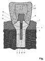
- FIG. 1 shows a schematic representation of a dental implant, a prosthetic post and a prosthetics (section, view of the vestibular).
- a one-piece dental implant 1 made of titanium, in which the endosseous implant bed and the abutment are integrally summarized, shown with a prosthesis attached thereto 11 as a cross section with a palatal look.
- the implant consists of a lower endosteal area 2, an upper endosteal area 3, a transgingival area 4 and a transgingival implant head 5.
- the lower endosseous region 2 which is located deep in the jawbone, has a honeycomb pattern, with tips in each case in the corners of the honeycombs. This proven structure allows for optimal ingrowth of the implant.
- the lower endosseous region 1 is adjoined by the upper endosteal region 3, which is shaped such that its upper edge extends to the upper edge of the comb-shaped jawbone 6.
- the area 3 is followed by the smoothly polished transgingival area 4.
- This area is shaped so that it extends circumferentially to about 1 mm below the gingival margin, which corresponds to about 1 mm in about the depth, up to which even a healthy tooth the gum is not fused with the tooth, but only lies loosely.
- the transgingival implant head 5 follows. In the flat portion of the implant head 1 is a hole 9, which is provided in the upper area by default with an internal thread 10.
- the dentist custom-shapes (upper line) the upper portion 8.2 of the pre-convected prosthetic post from its original geometry (dashed line) by subtractive (e.g., grinding) and additive (eg, plastic) techniques (solid line) Section 8.1 of the prosthetic post is screwed into the bore 10, the upper portion of the prosthetic post is molded and serves as a base for making the prosthesis which is then glued to the upper portion of the prosthetic post and the implant head.
- Panavia 2.0 and adhering to the recommended adhesive gap width of approx. 20 ⁇ m a permanent, elastic connection between the prosthetic post and the implant head 5 is ensured.
Description
Die Erfindung betrifft ein Zahnimplantatsystem mit einem Prothetikpfosten, das besonders vorteilhaft in Verbindung mit einem Zahnimplantatsystem gemäß
Üblicherweise bestehen Zahnimplantatsysteme (künstlicher Zahnersatz) aus drei Komponenten: einer künstlichen Wurzel (enossales Implantat), einem Verbindungsstück, dem so genannten Abutment, und einer Prothetik wie z. B. einer Krone oder einer Brücke.Usually dental implant systems (artificial dentures) consist of three components: an artificial root (endosseous implant), a connector, the so-called abutment, and a prosthetics such. B. a crown or a bridge.
Die Befestigung der Suprakonstruktion am Abutment mit Hilfe eines starren prothetischen Aufbaustifts (Prothetikpfostens) führt jedoch zu ungünstigen Kräfteverteilungen und Hebelverhältnissen, wodurch eine erhöhte Bruchgefahr besteht. Bei verschraubten Prothetikpfosten treten außerdem noch nachweisbar zerstörerische Mikrobewegungen auf.The attachment of the superstructure on the abutment with the aid of a rigid prosthetic post (prosthetic post), however, leads to unfavorable distribution of forces and leverage, resulting in an increased risk of breakage. Screw-retained prosthetic posts also show detectable destructive micromotion.
In den letzten Jahren wurde ein erheblicher Fortschritt in der Implantattechnik erreicht. So wurde mit
Dieses Zahnimplantatsystem setzt sich aus einem typischerweise wabenförmig oder gewindeförmig strukturierten unteren enossalen Bereich, einem sich nach oben hin aufweitenden oberen enossalen Bereich mit aufgerauter Oberfläche, einem transgingivalen Bereich mit glatter Wandfläche und einem transgingivalen Implantatkopf zusammen. Alle diese Bereiche schließen naht- und spaltlos aneinander an.This dental implant system consists of a typically lower honeycomb or lower alveolar endosseous region, a flared upper enossal region with a roughened surface, a transgingival region with a smooth wall surface, and a transgingival implant head. All these areas connect seamlessly and without gaps.
Auf die gesamte Fläche des Implantatkopfes ist eine Suprakonstruktion mit ihrer Unterseite, die der Form des Implantatkopfes angepasst ist, aufgeklebt oder aufzementiert. Diese Verbindung nimmt einen Großteil der zwischen Implantat und Suprakonstruktion wirkenden Kräfte auf. Zur Vermeidung einer seitlichen Verschiebung ist ein Prothetikpfosten ungefähr im Zentrum der Präparationsfläche in den transgingivalen Bereich des Implantats eingeschraubt und auf der anderen Seite mit der Suprakonstruktion verbunden. Die Basalfläche des Prothetikpfostens liegt auf dem flachen Teil des transgingivalen Implantatkopfes auf.On the entire surface of the implant head is a superstructure with its underside, which is adapted to the shape of the implant head, glued or cemented. This compound absorbs much of the forces acting between the implant and the superstructure. To avoid lateral displacement, a prosthetic post is screwed into the transgingival region of the implant approximately in the center of the preparation surface and connected to the superstructure on the other side. The basal surface of the prosthetic post rests on the flat part of the transgingival implant head.
Das Implantat ist vorteilhafterweise aus einem Stück (Rohling) hergestellt. Als medizintechnisch bewährte Materialien für des Implantat sowie den Prothetikpfosten werden Titan und Zirkonoxid bevorzugt.The implant is advantageously made of one piece (blank). Titanium and zirconium oxide are preferred as medical grade materials for the implant as well as the prosthetic post.
Titan, aber insbesondere Zirkonoxid weisen eine hohe Festigkeit und nur eine sehr geringe physikalische Elastizität auf. Die E-Moduln von Titan und Zirkonoxid betragen 105 bzw. 200 kN/mm2. Besteht der Prothetikpfosten aus einem dieser Materialien, werden die Kräfte, die beim Kauen auf die Suprakonstruktion (Prothetik) wirken, über den Prothetikpfosten direkt in das Implantat und von diesem auf den Kieferknochen übertragen. Diese starre Struktur entspricht nicht der natürlichen Aufhängung des Zahnes im Kiefer, welche elastisch ist.Titanium, but in particular zirconium oxide have a high strength and only a very low physical elasticity. The moduli of elasticity of titanium and zirconium oxide are 105 and 200 kN / mm 2, respectively. If the prosthetic post consists of one of these materials, the forces that act on the superstructure (prosthetics) during chewing are transmitted via the prosthetic post directly into the implant and from there to the jawbone. This rigid structure does not correspond to the natural suspension of the tooth in the jaw, which is elastic.
In
Aufgabe der Erfindung ist es, ein Zahnimplantatsystem mit einem Prothetikpfosten bereitzustellen, mit dem der Nachteil des Standes der Technik beseitigt wird, insbesondere soll ein kostengünstiger Prothetikpfosten geschaffen werden, durch dessen Einsatz in Zahnimplantatsystemen die natürliche, elastische Aufhängung des Zahnes im Knochen nachgebildet wird.The object of the invention is to provide a dental implant system with a prosthetic post, with which the disadvantage of the prior art is eliminated, in particular a cost-effective prosthetic post is to be created, by its use in dental implant systems, the natural, elastic suspension of the tooth is simulated in the bone.
Diese Aufgabe wird durch die Merkmale des Patentanspruchs 1 gelöst, vorteilhafte Ausgestaltungen ergeben sich aus den abhängigen Ansprüchen.This object is solved by the features of
Ausgegangen wird von einem Zahnimplantatsystem, das ein Zahnimplantat mit einer Bohrung und einen Prothetikpfosten aufweist, der zur mechanischen Befestigung der Prothetik an dem Zahnimplantat dient und der mechanisch mit dem Zahnimplantat verbunden wird. Der Prothetikpfosten besteht aus einem biokompatiblen Material mit einem E-Modul kleiner 100 kN/mm2. Er weist einen stabförmigen unteren Bereich auf, an den sei ein oberer Bereich anschließt, der zur Befestigung der Prothetik dient. Die Härte des Prothetikpfostens ist geringer als die des Zahnimplantats.The starting point is a dental implant system having a dental implant with a bore and a prosthetic post which serves for the mechanical attachment of the prosthetics to the dental implant and which is mechanically connected to the dental implant. The prosthetic post consists of a biocompatible material with an E-modulus of less than 100 kN / mm 2 . It has a rod-shaped lower area, to which an upper area is connected, which serves to attach the prosthetics. The hardness of the prosthetic post is less than that of the dental implant.
Nach Maßgabe der Erfindung ist die Bohrung im Zahnimplantat derart mit einem Innengewinde versehen, dass durch Eindrehen des glatt ausgeführten unteren Bereichs des Prothetikpfostens in die Bohrung des Zahnimplantats mittels des Innengewindes der Bohrung ein Gewinde in den unteren Bereich des Prothetikpfostens geschnitten wird.According to the invention, the bore in the dental implant is provided with an internal thread such that by screwing the smooth running lower portion of the prosthetic post into the bore of the dental implant by means of the internal thread of the bore a thread is cut into the lower portion of the prosthetic post.
Bei Faserwerkstoffen nehmen die Werte der E-Moduln abhängig von der Richtung sehr verschiedene Werte an. So beträgt z.B. bei kohlefaserverstärktem Kunststoff der E-Modul für parallel zu den Fasern und in Zugrichtung einwirkende Kräfte 140 bis 150 kN/mm2, wohingegen der E-Modul für seitlich zu den Fasern wirkende Kräfte lediglich 13 kN/mm2 beträgt. Auch für Kräfte die parallel zur Faserrichtung, jedoch in Druckrichtung wirken, werden E-Moduln kleiner 100 kN/mm2 gemessen.For fiber materials, the values of the moduli of elasticity assume very different values, depending on the direction. For example, in the case of carbon-fiber-reinforced plastic, the modulus of elasticity for forces acting parallel to the fibers and in the tensile direction is 140 to 150 kN / mm 2 , whereas the modulus of elasticity for forces acting laterally on the fibers is only 13 kN / mm 2 . For forces acting parallel to the fiber direction, but in the compression direction, moduli of elasticity less than 100 kN / mm 2 are measured.
Da von den über den Prothetikpfosten übertragenen Kräften nur die Druckkräfte und die seitlich wirkenden Kräfte kritisch sind, ist bei Auswahl von faserverstärkten Verbundwerkstoffen für den Prothetikpfosten darauf zu achten, dass die E-Moduln für seitlich zu den Fasern wirkende und für in Druckrichtung längs der Fasern wirkende Kräfte kleiner 100 kN/mm2 sind. Höhere E-Moduln in Zugrichtung der Fasern sind unkritisch.Since only the compressive forces and the lateral forces are critical of the forces transmitted through the prosthetic post, when selecting fiber reinforced composites for the prosthetic post, care must be taken to ensure that the moduli of elasticity are effective for the fibers laterally and compressively along the fibers acting forces are less than 100 kN / mm 2 . Higher moduli of elasticity in the tensile direction of the fibers are not critical.
Besonders geeignete Materialien für den Prothetikpfosten sind glasfaserverstärkte (GFK), kohlenstofffaserverstärkte (CFK) und aramidfaserverstärkte Kunststoffe sowie Polyetheretherketon (PEEK).Particularly suitable materials for the prosthetic post are glass fiber reinforced (GRP), carbon fiber reinforced (CFRP) and aramid fiber reinforced plastics and polyetheretherketone (PEEK).
Durch den Einsatz von Materialien mit höherer Elastizität (kleineren E-Moduln) werden erstens statisch wirkende Kräfte gleichmäßiger in das Zahnimplantat und letztendlich auch in den Kieferknochen eingeleitet, da durch die Elastizität des Prothetikpfostens, im Gegensatz zu Prothetikpfosten aus Materialien mit sehr geringen Elastizität an (Titan, Zirkonoxid), die Einleitung großer Kräfte an den Kanten vermieden wird; vielmehr verteilt sich die Krafteinwirkung auf die unterhalb der Kante liegenden Bereiche. Zweitens werden kurze Impulse mit sehr hohen Kräften (dynamisch wirkende Kräfte) gedämpft, indem die Kraftspitzen durch ein Verteilen über eine längere Zeit gemindert werden.By using materials with higher elasticity (smaller moduli of elasticity), first of all, statically acting forces are introduced more uniformly into the dental implant and ultimately also into the jawbone, since by the elasticity of the prosthetic post, in contrast to prosthetic posts made of materials with very low elasticity ( Titanium, zirconia), the introduction of large forces is avoided at the edges; rather, the force is distributed to the underlying areas below the edge. Secondly, short impulses with very high forces (dynamically acting forces) are damped by reducing the force peaks by distributing them over a longer period of time.
Hierdurch wird, im Gegensatz zu den üblicherweise verwendeten Implantaten mit starrer Kraftkopplung an den Kieferknochen, die natürliche, elastische Aufhängung des Zahnes im Knochen (Sharpey-Fasern) nachbildet. Das Implantat kann infolgedessen schneller in den Knochen einwachsen (Osseo-Integration). Durch die gleichmäßigere Krafteinleitung wird zudem der bei herkömmlichen Implantaten während der Tragzeit zwangsläufig auftretende Knochenabbau nachhaltig verringert, sodass generell höhere Tragzeiten erreichbar sind.As a result, in contrast to the implants with rigid force coupling to the jawbone, which are commonly used, the natural, elastic suspension of the tooth in the bone (Sharpey fibers) is simulated. As a result, the implant can grow faster into the bone (Osseo integration). In addition, the more uniform application of force permanently reduces the bone loss that inevitably occurs in conventional implants during the gestation period, so that generally higher wearing times can be achieved.
Es ist vorgesehen, vorkonfektionierte Prothetikpfosten mit einem stabförmigen unteren Bereich (Durchmesser vorzugsweise ca. 2,0 mm), der beim Befestigen der Prothetik vollständig in die Bohrung im Zahnimplantat eingebracht wird, und einem sich an den unteren Bereich anschließenden oberen Bereich mit einem größeren Durchmesser (ca. 4 bis 6 mm, teilweise parallelwandig bis hin zur konischen Abschrägung) basal (wo der Stift auf dem Kopf aufliegt) einzusetzen. Die sonstige Geometrie des Prothetikpfostens ist so gewählt, dass der Prothetikpfosten subtraktiv und/oder additiv an beliebige Prothetiken angepasst werden kann.It is envisaged prefabricated prosthetic posts with a rod-shaped lower portion (diameter preferably about 2.0 mm), which is completely inserted into the bore in the dental implant when attaching the prosthetics, and an upper region with a larger diameter adjoining the lower region (about 4 to 6 mm, partially parallel-walled up to the conical bevel) basal (where the pin rests on the head) use. The other geometry of the prosthetic post is chosen so that the prosthetic post can be subtractive and / or additively adapted to any prosthetic.
Das erfindungsgemäße Zahnimplantatsystem mit Prothetikpfosten kann besonders vorteilhaft in Verbindung mit einem Zahnimplantatsystem eingesetzt werden, bei dem das Zahnimplantat sowohl das enossale Zahnimplantat (Zahnimplantat ohne Abutment) als auch das Abutment funktional umfasst (s.
Mit dem erfindungsgemäßen Zahnimplantatsystem bzw. dessen Prothetikpfosten werden des Weiteren zwei wirtschaftliche Vorteile erreicht: erstens können die Prothetikpfosten, da sie vorkonfektionierbar sind, sehr kostengünstig hergestellt werden. Zweitens findet, im Gegensatz zur sonst üblichen Praxis, bei der mit einem integrierten Prothetikpfosten ausgestattete Abutments verwendet werden, beim Einsatz des erfindungsgemäßen Prothetikpfostens aufgrund der erforderlichen Anpassung für die Prothetik, wieder ein größerer Anteil der Wertschöpfung in den Zahnarztpraxen statt. Da meistens die Zahnärzte entscheiden, welches Zahnimplantatsystem zum Einsatz kommt, ist dies vorteilhaft für die Marktakzeptanz des erfindungsgemäßen Prothetikpfostens, bzw. von Zahnimplantatsystemen, die diesen verwenden.With the dental implant system according to the invention or its prosthetic post, two further economic advantages are achieved: firstly, since the prosthetic posts can be prefabricated, they can be produced very inexpensively. Secondly, in contrast to the usual practice, in the case of abutments equipped with an integrated prosthetic post, when the prosthetic post according to the invention is used again, a greater share of the added value takes place in the dental practices due to the required adaptation for the prosthetics. Since mostly the dentists decide which dental implant system is used, this is advantageous for the market acceptance of the prosthetic post according to the invention, or of dental implant systems that use this.
Im Zahnimplantatsystem werden damit die mechanischen Belastungen mittels einer großflächigen kraftschlüssigen Verbindung, gebildet durch die Verschraubung zwischen dem Implantatkopf und der Unterseite der Prothetik, aufgenommen. Der verwendete Prothetikpfosten hat eine unterstützende Funktion, verhindert ein seitliches Verschieben während des Einbringens der Prothetik und fungiert durch die basale Auflage auf dem flachen Teil des transgingivalen Implantatkopfes bei seitlich einfallenden Kräften als kraftaufnehmendes Element.In the dental implant system, the mechanical loads are thus absorbed by means of a large-area frictional connection formed by the screw connection between the implant head and the underside of the prosthesis. The prosthetic post used has a supporting function, prevents lateral displacement during insertion of the prosthetics and acts by the basal support on the flat part of the transgingival implant head with laterally incident forces as a force-absorbing element.
Die Erfindung wird nachfolgend anhand eines Ausführungsbeispiels näher erläutert; hierzu zeigt die Figur in schematischer Darstellung ein Zahnimplantat, einen Prothetikpfosten und eine Prothetik (Schnitt; Ansicht von vestibulär).The invention will be explained in more detail with reference to an embodiment; To this end, the figure shows a schematic representation of a dental implant, a prosthetic post and a prosthetics (section, view of the vestibular).
Es ist ein einteiliges Zahnimplantat 1 aus Titan, bei dem das enossale Implantatbett und das Abutment integrativ zusammengefasst sind, mit einer daran befestigten Prothetik 11 als Querschnitt mit palatinaler Blickrichtung dargestellt. Das Implantat besteht aus einem unteren enossalen Bereich 2, einem oberen enossalen Bereich 3, einem transgingivalen Bereich 4 und einem transgingivalen Implantatkopf 5.It is a one-piece
Der tief im Kieferknochen sitzende, untere enossale Bereich 2 weist ein Wabenmuster auf, wobei sich jeweils in den Ecken der Waben Spitzen befinden. Diese bewährte Struktur ermöglicht ein optimales Einwachsen des Implantats.The lower
An den unteren enossalen Bereich 1 schließt sich der obere enossale Bereich 3 an, der so ausgeformt ist, dass sein oberer Rand bis zur Oberkante des kammförmigen Kieferknochens 6 reicht.The lower
Dem Bereich 3 folgt der glatt polierte transgingivale Bereich 4. Dieser Bereich ist derart geformt, dass er umlaufend bis ca. 1 mm unterhalb des Zahnfleischsaums reicht, wobei dieser ca. 1 mm in etwa der Tiefe entspricht, bis zu welcher auch bei einem gesunden Zahn das Zahnfleisch nicht mit dem Zahn verwachsen ist, sondern lediglich lose anliegt.The
An das Ende des transgingivalen Bereichs 4, das gleichzeitig die Präparationsgrenze 12 bildet, schließt sich der transgingivale Implantatkopf 5 an. Im flachen Teilbereich des Implantatkopfes 1 befindet sich eine Bohrung 9, die im oberen Bereich standardmäßig mit einem Innengewinde 10 versehen ist. Vor dem Anfertigen der Prothetik wird vom Zahnarzt der obere Bereich 8.2 des vorkonvektionierten Prothetikpfostens von seiner ursprünglichen Geometrie (gestrichelte Linie) durch subtraktive (z. B. Schleifen) sowie additive (z. B. Kunststoffantrag) Techniken individuell geformt (durchgezogene Linie) Der untere Bereich 8.1 des Prothetikpfostens wird in die Bohrung 10 eingeschraubt, der obere Bereich des Prothetikpfostens wird abgeformt und dient als Basis zur Herstellung der Prothetik die anschließend mit dem oberen Bereich des Prothetikpfostens und dem Implantatkopf verklebt wird. Durch die Verwendung von Panavia 2.0 und die Einhaltung der empfohlenen Klebespaltbreite von ca. 20 µm wird eine dauerhafte, elastische Verbindung zwischen dem Prothetikpfosten und dem Implantatkopf 5 sichergestellt.At the end of the
- 1. Zahnimplantat1. Dental implant
- 2. unterer enossaler Bereich2nd lower enossal area
- 3. oberer enossaler Bereich3rd upper endossal area
- 4. transgingivaler Bereich4. transgingival area
- 5. transgingivaler Implantatkopf5. transgingival implant head
- 6. Kieferknochen6. Jawbone
- 7. Zahnfleisch7. gums
- 8.1 unterer Bereich des Prothetikpfostens8.1 lower portion of the prosthetic post
-
8.2 oberer Bereich des Prothetikpfostens 9. Bohrung8.2 Upper area of the
prosthetic post 9. Bore - 10. Innengewinde10. internal thread
- 11. Prothetik11. Prosthetics
- 12. Präparationsgrenze/Kante12. Preparation margin / edge
Claims (8)
- A dental implant system, comprising an abutment (8), which is used to mechanically secure the prosthetic (11) to a dental implant (1) and can be mechanically connected to the dental implant (11), the abutment (8) being made of a biocompatible material having a modulus of elasticity of less than 100 kN/mm2, a rod-shaped lower region (8.1), which is smooth, an upper region (8.2), which adjoins the lower region (8.1) and is used to secure the prosthetic (11), the hardness of the abutment (8) being lower than that of the dental implant (1), and a dental implant (1) having a borehole (9), characterized in that the borehole (9) is provided with an internal thread (10), so that a thread is cut into the lower region (8.1) of the abutment (8) when screwing the smooth lower region (8.1) of the abutment (8) into this borehole (9) by way of the internal thread (10).
- The dental implant system according to claim 1, characterized in that the lower region (8.1) of the abutment (8) is intended to be fully introduced into the dental implant (1).
- The dental implant system according to claim 1 or 2, characterized in that the lower region (8.1) has a diameter of approximately 2 mm and the upper region (8.2) has a larger diameter of approximately 4 mm to 6 mm, the geometry of the upper region (8.2) being selected so that this region can be adapted to any arbitrary prosthetics (11) by way of subtraction and/or addition.
- A dental implant system according to any one of claims 1 to 3, characterized in that the lower region is made of a glass fiber-reinforced plastic material.
- A dental implant system according to any one of claims 1 to 3, characterized in that the lower region is made of a carbon fiber-reinforced plastic material.
- A dental implant system according to any one of claims 1 to 3, characterized in that the lower region is made of an aramid fiber-reinforced plastic material.
- A dental implant system according to any one of claims 1 to 3, characterized in that the lower region is made of polyetheretherketone.
- A dental implant system according to any one of claims 1 to 7, characterized in that the dental implant (1) is designed as one cohesive piece, which functionally comprises both the endosseous dental implant and the abutment.
Priority Applications (1)
| Application Number | Priority Date | Filing Date | Title |
|---|---|---|---|
| PL10767915T PL2470112T3 (en) | 2009-08-29 | 2010-08-13 | Dental implant system with a prosthetic post |
Applications Claiming Priority (2)
| Application Number | Priority Date | Filing Date | Title |
|---|---|---|---|
| DE202009011750U DE202009011750U1 (en) | 2009-08-29 | 2009-08-29 | Dental implant system |
| PCT/DE2010/075076 WO2011023189A1 (en) | 2009-08-29 | 2010-08-13 | Prosthetic post |
Publications (2)
| Publication Number | Publication Date |
|---|---|
| EP2470112A1 EP2470112A1 (en) | 2012-07-04 |
| EP2470112B1 true EP2470112B1 (en) | 2013-10-02 |
Family
ID=41361123
Family Applications (1)
| Application Number | Title | Priority Date | Filing Date |
|---|---|---|---|
| EP10767915.1A Active EP2470112B1 (en) | 2009-08-29 | 2010-08-13 | Dental implant system with a prosthetic post |
Country Status (6)
| Country | Link |
|---|---|
| EP (1) | EP2470112B1 (en) |
| DE (1) | DE202009011750U1 (en) |
| DK (1) | DK2470112T3 (en) |
| ES (1) | ES2441229T3 (en) |
| PL (1) | PL2470112T3 (en) |
| WO (1) | WO2011023189A1 (en) |
Families Citing this family (2)
| Publication number | Priority date | Publication date | Assignee | Title |
|---|---|---|---|---|
| DE102013006829B4 (en) * | 2013-04-22 | 2019-04-25 | Andreas Dmoch | Zirkondioxidimplantateinheit |
| DE102013211175A1 (en) * | 2013-06-14 | 2014-12-18 | R + K CAD/CAM Technologie GmbH & Co. KG | Production of semi-finished products for implants based on plastic |
Family Cites Families (6)
| Publication number | Priority date | Publication date | Assignee | Title |
|---|---|---|---|---|
| FR2508307A1 (en) * | 1981-09-16 | 1982-12-31 | Lonca Philippe | NEW DENTAL IMPLANTS AND ANCILLARY EQUIPMENT FOR THEIR IMPLEMENTATION |
| EP1319375A1 (en) * | 2001-12-11 | 2003-06-18 | Antonio Presta | Implant pin made of fibers for prosthodontic use, and stump reconstruction system |
| EP1967157A1 (en) * | 2007-03-05 | 2008-09-10 | Ziterion GmbH | Hybrid two-part dental implant |
| DE102007018453B3 (en) | 2007-04-17 | 2008-10-23 | Dental Service Center Michael Menzel Gmbh | Dental implant system |
| DE102007026325B4 (en) * | 2007-04-20 | 2019-05-09 | Zv3 - Zircon Vision Gmbh | Artificial dentures |
| ES2351231T3 (en) * | 2007-05-12 | 2011-02-01 | Gerd Axel Dr. Walther | DENTAL IMPLANT, IN PARTICULAR OF A CERAMIC MATERIAL. |
-
2009
- 2009-08-29 DE DE202009011750U patent/DE202009011750U1/en not_active Expired - Lifetime
-
2010
- 2010-08-13 EP EP10767915.1A patent/EP2470112B1/en active Active
- 2010-08-13 DK DK10767915.1T patent/DK2470112T3/en active
- 2010-08-13 WO PCT/DE2010/075076 patent/WO2011023189A1/en active Application Filing
- 2010-08-13 PL PL10767915T patent/PL2470112T3/en unknown
- 2010-08-13 ES ES10767915.1T patent/ES2441229T3/en active Active
Also Published As
| Publication number | Publication date |
|---|---|
| PL2470112T3 (en) | 2014-03-31 |
| WO2011023189A4 (en) | 2011-04-21 |
| DK2470112T3 (en) | 2014-01-13 |
| DE202009011750U1 (en) | 2009-11-26 |
| ES2441229T3 (en) | 2014-02-03 |
| WO2011023189A1 (en) | 2011-03-03 |
| EP2470112A1 (en) | 2012-07-04 |
Similar Documents
| Publication | Publication Date | Title |
|---|---|---|
| DE4028857C2 (en) | ||
| DE102012201092B4 (en) | Dental implant system | |
| EP2142136B1 (en) | Dental implant system | |
| DE102007026325B4 (en) | Artificial dentures | |
| EP2874564B1 (en) | Dental implant abutment system | |
| EP2040638A1 (en) | Tooth implant with machinable construction | |
| DE102005006979A1 (en) | Ceramic endosseous dental implant | |
| WO2008086978A1 (en) | Method relating to implants, and a machine-readable medium and a computer | |
| EP2874563B1 (en) | Abutment system for immediate implants for producing a dental prosthesis | |
| EP2734145B1 (en) | Abutment for an artificial dental prosthesis | |
| DE102007018453B3 (en) | Dental implant system | |
| DE102012024596A1 (en) | Dental implant | |
| EP2470112B1 (en) | Dental implant system with a prosthetic post | |
| EP2800538B9 (en) | Dental implant | |
| EP1336388A1 (en) | Dental implant | |
| WO2012069178A1 (en) | Dental implant system | |
| DE10337462B4 (en) | connecting device | |
| DE202008001585U1 (en) | Implant with attached micro-thread | |
| DE19935414B4 (en) | Supraconstruction for anchoring a ceramic structure on a dental implant | |
| EP3964164A1 (en) | Method for producing a dental prosthesis, blank, and dental prosthesis | |
| DE202010002259U1 (en) | One-piece dental implant made of zirconium oxide ceramic | |
| WO2014203225A1 (en) | Dental implant having short post | |
| DE102008029023A1 (en) | Ball head attachment e.g. for dental implants, has body which through implant mounting screw is screwed to implant for mounting to dental prosthetic superstructure construction on implant | |
| DE202009000560U1 (en) | Multifunctional screw implant | |
| DE102008017086A1 (en) | Dental implant system, has transgingival region confined upwards by transgingival implant head, where circumferential edge that is formed by abutting head and transgingival region runs under gingival edge after implantation |
Legal Events
| Date | Code | Title | Description |
|---|---|---|---|
| PUAI | Public reference made under article 153(3) epc to a published international application that has entered the european phase |
Free format text: ORIGINAL CODE: 0009012 |
|
| 17P | Request for examination filed |
Effective date: 20120301 |
|
| AK | Designated contracting states |
Kind code of ref document: A1 Designated state(s): AL AT BE BG CH CY CZ DE DK EE ES FI FR GB GR HR HU IE IS IT LI LT LU LV MC MK MT NL NO PL PT RO SE SI SK SM TR |
|
| DAX | Request for extension of the european patent (deleted) | ||
| 17Q | First examination report despatched |
Effective date: 20130107 |
|
| GRAP | Despatch of communication of intention to grant a patent |
Free format text: ORIGINAL CODE: EPIDOSNIGR1 |
|
| INTG | Intention to grant announced |
Effective date: 20130424 |
|
| GRAS | Grant fee paid |
Free format text: ORIGINAL CODE: EPIDOSNIGR3 |
|
| GRAA | (expected) grant |
Free format text: ORIGINAL CODE: 0009210 |
|
| AK | Designated contracting states |
Kind code of ref document: B1 Designated state(s): AL AT BE BG CH CY CZ DE DK EE ES FI FR GB GR HR HU IE IS IT LI LT LU LV MC MK MT NL NO PL PT RO SE SI SK SM TR |
|
| REG | Reference to a national code |
Ref country code: GB Ref legal event code: FG4D Free format text: NOT ENGLISH |
|
| REG | Reference to a national code |
Ref country code: CH Ref legal event code: EP Ref country code: AT Ref legal event code: REF Ref document number: 634231 Country of ref document: AT Kind code of ref document: T Effective date: 20131015 |
|
| REG | Reference to a national code |
Ref country code: IE Ref legal event code: FG4D Free format text: LANGUAGE OF EP DOCUMENT: GERMAN |
|
| REG | Reference to a national code |
Ref country code: DE Ref legal event code: R096 Ref document number: 502010004954 Country of ref document: DE Effective date: 20131128 |
|
| REG | Reference to a national code |
Ref country code: DK Ref legal event code: T3 Effective date: 20140107 |
|
| REG | Reference to a national code |
Ref country code: NL Ref legal event code: T3 |
|
| REG | Reference to a national code |
Ref country code: SE Ref legal event code: TRGR |
|
| REG | Reference to a national code |
Ref country code: ES Ref legal event code: FG2A Ref document number: 2441229 Country of ref document: ES Kind code of ref document: T3 Effective date: 20140203 |
|
| REG | Reference to a national code |
Ref country code: NO Ref legal event code: T2 Effective date: 20131002 |
|
| PG25 | Lapsed in a contracting state [announced via postgrant information from national office to epo] |
Ref country code: SI Free format text: LAPSE BECAUSE OF FAILURE TO SUBMIT A TRANSLATION OF THE DESCRIPTION OR TO PAY THE FEE WITHIN THE PRESCRIBED TIME-LIMIT Effective date: 20131002 |
|
| REG | Reference to a national code |
Ref country code: LT Ref legal event code: MG4D |
|
| PG25 | Lapsed in a contracting state [announced via postgrant information from national office to epo] |
Ref country code: LT Free format text: LAPSE BECAUSE OF FAILURE TO SUBMIT A TRANSLATION OF THE DESCRIPTION OR TO PAY THE FEE WITHIN THE PRESCRIBED TIME-LIMIT Effective date: 20131002 Ref country code: HR Free format text: LAPSE BECAUSE OF FAILURE TO SUBMIT A TRANSLATION OF THE DESCRIPTION OR TO PAY THE FEE WITHIN THE PRESCRIBED TIME-LIMIT Effective date: 20131002 Ref country code: IS Free format text: LAPSE BECAUSE OF FAILURE TO SUBMIT A TRANSLATION OF THE DESCRIPTION OR TO PAY THE FEE WITHIN THE PRESCRIBED TIME-LIMIT Effective date: 20140202 Ref country code: FI Free format text: LAPSE BECAUSE OF FAILURE TO SUBMIT A TRANSLATION OF THE DESCRIPTION OR TO PAY THE FEE WITHIN THE PRESCRIBED TIME-LIMIT Effective date: 20131002 |
|
| PG25 | Lapsed in a contracting state [announced via postgrant information from national office to epo] |
Ref country code: LV Free format text: LAPSE BECAUSE OF FAILURE TO SUBMIT A TRANSLATION OF THE DESCRIPTION OR TO PAY THE FEE WITHIN THE PRESCRIBED TIME-LIMIT Effective date: 20131002 Ref country code: CY Free format text: LAPSE BECAUSE OF FAILURE TO SUBMIT A TRANSLATION OF THE DESCRIPTION OR TO PAY THE FEE WITHIN THE PRESCRIBED TIME-LIMIT Effective date: 20131002 |
|
| PG25 | Lapsed in a contracting state [announced via postgrant information from national office to epo] |
Ref country code: PT Free format text: LAPSE BECAUSE OF FAILURE TO SUBMIT A TRANSLATION OF THE DESCRIPTION OR TO PAY THE FEE WITHIN THE PRESCRIBED TIME-LIMIT Effective date: 20140203 |
|
| REG | Reference to a national code |
Ref country code: DE Ref legal event code: R097 Ref document number: 502010004954 Country of ref document: DE |
|
| PG25 | Lapsed in a contracting state [announced via postgrant information from national office to epo] |
Ref country code: EE Free format text: LAPSE BECAUSE OF FAILURE TO SUBMIT A TRANSLATION OF THE DESCRIPTION OR TO PAY THE FEE WITHIN THE PRESCRIBED TIME-LIMIT Effective date: 20131002 |
|
| PLBE | No opposition filed within time limit |
Free format text: ORIGINAL CODE: 0009261 |
|
| STAA | Information on the status of an ep patent application or granted ep patent |
Free format text: STATUS: NO OPPOSITION FILED WITHIN TIME LIMIT |
|
| PG25 | Lapsed in a contracting state [announced via postgrant information from national office to epo] |
Ref country code: SK Free format text: LAPSE BECAUSE OF FAILURE TO SUBMIT A TRANSLATION OF THE DESCRIPTION OR TO PAY THE FEE WITHIN THE PRESCRIBED TIME-LIMIT Effective date: 20131002 Ref country code: RO Free format text: LAPSE BECAUSE OF FAILURE TO SUBMIT A TRANSLATION OF THE DESCRIPTION OR TO PAY THE FEE WITHIN THE PRESCRIBED TIME-LIMIT Effective date: 20131002 |
|
| 26N | No opposition filed |
Effective date: 20140703 |
|
| REG | Reference to a national code |
Ref country code: DE Ref legal event code: R097 Ref document number: 502010004954 Country of ref document: DE Effective date: 20140703 |
|
| PG25 | Lapsed in a contracting state [announced via postgrant information from national office to epo] |
Ref country code: SM Free format text: LAPSE BECAUSE OF FAILURE TO SUBMIT A TRANSLATION OF THE DESCRIPTION OR TO PAY THE FEE WITHIN THE PRESCRIBED TIME-LIMIT Effective date: 20131002 |
|
| PG25 | Lapsed in a contracting state [announced via postgrant information from national office to epo] |
Ref country code: MT Free format text: LAPSE BECAUSE OF FAILURE TO SUBMIT A TRANSLATION OF THE DESCRIPTION OR TO PAY THE FEE WITHIN THE PRESCRIBED TIME-LIMIT Effective date: 20131002 Ref country code: GR Free format text: LAPSE BECAUSE OF FAILURE TO SUBMIT A TRANSLATION OF THE DESCRIPTION OR TO PAY THE FEE WITHIN THE PRESCRIBED TIME-LIMIT Effective date: 20140103 Ref country code: BG Free format text: LAPSE BECAUSE OF FAILURE TO SUBMIT A TRANSLATION OF THE DESCRIPTION OR TO PAY THE FEE WITHIN THE PRESCRIBED TIME-LIMIT Effective date: 20131002 |
|
| PG25 | Lapsed in a contracting state [announced via postgrant information from national office to epo] |
Ref country code: HU Free format text: LAPSE BECAUSE OF FAILURE TO SUBMIT A TRANSLATION OF THE DESCRIPTION OR TO PAY THE FEE WITHIN THE PRESCRIBED TIME-LIMIT; INVALID AB INITIO Effective date: 20100813 |
|
| REG | Reference to a national code |
Ref country code: FR Ref legal event code: PLFP Year of fee payment: 7 |
|
| PGFP | Annual fee paid to national office [announced via postgrant information from national office to epo] |
Ref country code: NL Payment date: 20160824 Year of fee payment: 7 Ref country code: LU Payment date: 20160830 Year of fee payment: 7 |
|
| PGFP | Annual fee paid to national office [announced via postgrant information from national office to epo] |
Ref country code: NO Payment date: 20160826 Year of fee payment: 7 Ref country code: IE Payment date: 20160830 Year of fee payment: 7 Ref country code: DK Payment date: 20160824 Year of fee payment: 7 Ref country code: MC Payment date: 20160825 Year of fee payment: 7 |
|
| PGFP | Annual fee paid to national office [announced via postgrant information from national office to epo] |
Ref country code: PL Payment date: 20160902 Year of fee payment: 7 Ref country code: CZ Payment date: 20160909 Year of fee payment: 7 Ref country code: SE Payment date: 20160823 Year of fee payment: 7 |
|
| PGFP | Annual fee paid to national office [announced via postgrant information from national office to epo] |
Ref country code: BE Payment date: 20160824 Year of fee payment: 7 Ref country code: TR Payment date: 20160902 Year of fee payment: 7 |
|
| REG | Reference to a national code |
Ref country code: FR Ref legal event code: PLFP Year of fee payment: 8 |
|
| REG | Reference to a national code |
Ref country code: DK Ref legal event code: EBP Effective date: 20170831 Ref country code: NO Ref legal event code: MMEP |
|
| PG25 | Lapsed in a contracting state [announced via postgrant information from national office to epo] |
Ref country code: MC Free format text: LAPSE BECAUSE OF NON-PAYMENT OF DUE FEES Effective date: 20170831 |
|
| REG | Reference to a national code |
Ref country code: NL Ref legal event code: MM Effective date: 20170901 |
|
| PG25 | Lapsed in a contracting state [announced via postgrant information from national office to epo] |
Ref country code: CZ Free format text: LAPSE BECAUSE OF NON-PAYMENT OF DUE FEES Effective date: 20170813 Ref country code: NO Free format text: LAPSE BECAUSE OF NON-PAYMENT OF DUE FEES Effective date: 20170831 Ref country code: SE Free format text: LAPSE BECAUSE OF NON-PAYMENT OF DUE FEES Effective date: 20170814 |
|
| REG | Reference to a national code |
Ref country code: BE Ref legal event code: MM Effective date: 20170831 |
|
| REG | Reference to a national code |
Ref country code: IE Ref legal event code: MM4A |
|
| PG25 | Lapsed in a contracting state [announced via postgrant information from national office to epo] |
Ref country code: MK Free format text: LAPSE BECAUSE OF FAILURE TO SUBMIT A TRANSLATION OF THE DESCRIPTION OR TO PAY THE FEE WITHIN THE PRESCRIBED TIME-LIMIT Effective date: 20131002 Ref country code: LU Free format text: LAPSE BECAUSE OF NON-PAYMENT OF DUE FEES Effective date: 20170813 Ref country code: NL Free format text: LAPSE BECAUSE OF NON-PAYMENT OF DUE FEES Effective date: 20170901 |
|
| PG25 | Lapsed in a contracting state [announced via postgrant information from national office to epo] |
Ref country code: DK Free format text: LAPSE BECAUSE OF NON-PAYMENT OF DUE FEES Effective date: 20170831 Ref country code: IE Free format text: LAPSE BECAUSE OF NON-PAYMENT OF DUE FEES Effective date: 20170813 |
|
| REG | Reference to a national code |
Ref country code: FR Ref legal event code: PLFP Year of fee payment: 9 |
|
| PG25 | Lapsed in a contracting state [announced via postgrant information from national office to epo] |
Ref country code: BE Free format text: LAPSE BECAUSE OF NON-PAYMENT OF DUE FEES Effective date: 20170831 |
|
| PG25 | Lapsed in a contracting state [announced via postgrant information from national office to epo] |
Ref country code: AL Free format text: LAPSE BECAUSE OF FAILURE TO SUBMIT A TRANSLATION OF THE DESCRIPTION OR TO PAY THE FEE WITHIN THE PRESCRIBED TIME-LIMIT Effective date: 20131002 |
|
| PGFP | Annual fee paid to national office [announced via postgrant information from national office to epo] |
Ref country code: IT Payment date: 20180829 Year of fee payment: 9 Ref country code: ES Payment date: 20180921 Year of fee payment: 9 Ref country code: FR Payment date: 20180824 Year of fee payment: 9 |
|
| PGFP | Annual fee paid to national office [announced via postgrant information from national office to epo] |
Ref country code: AT Payment date: 20180824 Year of fee payment: 9 Ref country code: CH Payment date: 20180924 Year of fee payment: 9 Ref country code: GB Payment date: 20180828 Year of fee payment: 9 |
|
| PG25 | Lapsed in a contracting state [announced via postgrant information from national office to epo] |
Ref country code: PL Free format text: LAPSE BECAUSE OF NON-PAYMENT OF DUE FEES Effective date: 20170813 |
|
| REG | Reference to a national code |
Ref country code: DE Ref legal event code: R084 Ref document number: 502010004954 Country of ref document: DE |
|
| REG | Reference to a national code |
Ref country code: AT Ref legal event code: MM01 Ref document number: 634231 Country of ref document: AT Kind code of ref document: T Effective date: 20190813 |
|
| GBPC | Gb: european patent ceased through non-payment of renewal fee |
Effective date: 20190813 |
|
| PG25 | Lapsed in a contracting state [announced via postgrant information from national office to epo] |
Ref country code: AT Free format text: LAPSE BECAUSE OF NON-PAYMENT OF DUE FEES Effective date: 20190813 |
|
| PG25 | Lapsed in a contracting state [announced via postgrant information from national office to epo] |
Ref country code: CH Free format text: LAPSE BECAUSE OF NON-PAYMENT OF DUE FEES Effective date: 20190831 Ref country code: LI Free format text: LAPSE BECAUSE OF NON-PAYMENT OF DUE FEES Effective date: 20190831 |
|
| PG25 | Lapsed in a contracting state [announced via postgrant information from national office to epo] |
Ref country code: FR Free format text: LAPSE BECAUSE OF NON-PAYMENT OF DUE FEES Effective date: 20190831 |
|
| PG25 | Lapsed in a contracting state [announced via postgrant information from national office to epo] |
Ref country code: IT Free format text: LAPSE BECAUSE OF NON-PAYMENT OF DUE FEES Effective date: 20190813 Ref country code: GB Free format text: LAPSE BECAUSE OF NON-PAYMENT OF DUE FEES Effective date: 20190813 |
|
| REG | Reference to a national code |
Ref country code: ES Ref legal event code: FD2A Effective date: 20210107 |
|
| PG25 | Lapsed in a contracting state [announced via postgrant information from national office to epo] |
Ref country code: ES Free format text: LAPSE BECAUSE OF NON-PAYMENT OF DUE FEES Effective date: 20190814 |
|
| REG | Reference to a national code |
Ref country code: DE Ref legal event code: R082 Ref document number: 502010004954 Country of ref document: DE Representative=s name: WERNER, ANDRE, DR., DE |
|
| PG25 | Lapsed in a contracting state [announced via postgrant information from national office to epo] |
Ref country code: TR Free format text: LAPSE BECAUSE OF NON-PAYMENT OF DUE FEES Effective date: 20170813 |
|
| PGFP | Annual fee paid to national office [announced via postgrant information from national office to epo] |
Ref country code: DE Payment date: 20220921 Year of fee payment: 13 |