EP2470059B1 - Laryngoscope system - Google Patents
Laryngoscope system Download PDFInfo
- Publication number
- EP2470059B1 EP2470059B1 EP10754963.6A EP10754963A EP2470059B1 EP 2470059 B1 EP2470059 B1 EP 2470059B1 EP 10754963 A EP10754963 A EP 10754963A EP 2470059 B1 EP2470059 B1 EP 2470059B1
- Authority
- EP
- European Patent Office
- Prior art keywords
- blade
- laryngoscope
- camera
- sleeve
- distal end
- Prior art date
- Legal status (The legal status is an assumption and is not a legal conclusion. Google has not performed a legal analysis and makes no representation as to the accuracy of the status listed.)
- Active
Links
- 238000002627 tracheal intubation Methods 0.000 claims description 18
- 230000003287 optical effect Effects 0.000 claims description 4
- 230000037361 pathway Effects 0.000 claims description 4
- 230000000007 visual effect Effects 0.000 description 6
- 210000003437 trachea Anatomy 0.000 description 4
- 230000005856 abnormality Effects 0.000 description 2
- 210000002409 epiglottis Anatomy 0.000 description 2
- 239000000835 fiber Substances 0.000 description 2
- 210000004704 glottis Anatomy 0.000 description 2
- 210000000867 larynx Anatomy 0.000 description 2
- 238000012800 visualization Methods 0.000 description 2
- 206010057441 Laryngeal injury Diseases 0.000 description 1
- 208000027418 Wounds and injury Diseases 0.000 description 1
- 210000003484 anatomy Anatomy 0.000 description 1
- 230000009286 beneficial effect Effects 0.000 description 1
- 238000010276 construction Methods 0.000 description 1
- 238000011109 contamination Methods 0.000 description 1
- 238000012864 cross contamination Methods 0.000 description 1
- 230000006378 damage Effects 0.000 description 1
- 238000006073 displacement reaction Methods 0.000 description 1
- 239000003292 glue Substances 0.000 description 1
- 238000001746 injection moulding Methods 0.000 description 1
- 208000014674 injury Diseases 0.000 description 1
- 238000003780 insertion Methods 0.000 description 1
- 230000037431 insertion Effects 0.000 description 1
- 238000007689 inspection Methods 0.000 description 1
- 238000004519 manufacturing process Methods 0.000 description 1
- 239000000463 material Substances 0.000 description 1
- 239000002184 metal Substances 0.000 description 1
- 229910052751 metal Inorganic materials 0.000 description 1
- 150000002739 metals Chemical class 0.000 description 1
- 210000003300 oropharynx Anatomy 0.000 description 1
- 239000004033 plastic Substances 0.000 description 1
- 229920003023 plastic Polymers 0.000 description 1
- 229910001220 stainless steel Inorganic materials 0.000 description 1
- 239000010935 stainless steel Substances 0.000 description 1
- 238000004659 sterilization and disinfection Methods 0.000 description 1
- 239000012780 transparent material Substances 0.000 description 1
- 210000001260 vocal cord Anatomy 0.000 description 1
Images


Classifications
-
- A—HUMAN NECESSITIES
- A61—MEDICAL OR VETERINARY SCIENCE; HYGIENE
- A61B—DIAGNOSIS; SURGERY; IDENTIFICATION
- A61B1/00—Instruments for performing medical examinations of the interior of cavities or tubes of the body by visual or photographical inspection, e.g. endoscopes; Illuminating arrangements therefor
- A61B1/04—Instruments for performing medical examinations of the interior of cavities or tubes of the body by visual or photographical inspection, e.g. endoscopes; Illuminating arrangements therefor combined with photographic or television appliances
- A61B1/05—Instruments for performing medical examinations of the interior of cavities or tubes of the body by visual or photographical inspection, e.g. endoscopes; Illuminating arrangements therefor combined with photographic or television appliances characterised by the image sensor, e.g. camera, being in the distal end portion
-
- A—HUMAN NECESSITIES
- A61—MEDICAL OR VETERINARY SCIENCE; HYGIENE
- A61B—DIAGNOSIS; SURGERY; IDENTIFICATION
- A61B1/00—Instruments for performing medical examinations of the interior of cavities or tubes of the body by visual or photographical inspection, e.g. endoscopes; Illuminating arrangements therefor
- A61B1/00064—Constructional details of the endoscope body
- A61B1/00071—Insertion part of the endoscope body
- A61B1/0008—Insertion part of the endoscope body characterised by distal tip features
- A61B1/00096—Optical elements
-
- A—HUMAN NECESSITIES
- A61—MEDICAL OR VETERINARY SCIENCE; HYGIENE
- A61B—DIAGNOSIS; SURGERY; IDENTIFICATION
- A61B1/00—Instruments for performing medical examinations of the interior of cavities or tubes of the body by visual or photographical inspection, e.g. endoscopes; Illuminating arrangements therefor
- A61B1/00163—Optical arrangements
- A61B1/00174—Optical arrangements characterised by the viewing angles
- A61B1/00183—Optical arrangements characterised by the viewing angles for variable viewing angles
-
- A—HUMAN NECESSITIES
- A61—MEDICAL OR VETERINARY SCIENCE; HYGIENE
- A61B—DIAGNOSIS; SURGERY; IDENTIFICATION
- A61B1/00—Instruments for performing medical examinations of the interior of cavities or tubes of the body by visual or photographical inspection, e.g. endoscopes; Illuminating arrangements therefor
- A61B1/04—Instruments for performing medical examinations of the interior of cavities or tubes of the body by visual or photographical inspection, e.g. endoscopes; Illuminating arrangements therefor combined with photographic or television appliances
- A61B1/045—Control thereof
-
- A—HUMAN NECESSITIES
- A61—MEDICAL OR VETERINARY SCIENCE; HYGIENE
- A61B—DIAGNOSIS; SURGERY; IDENTIFICATION
- A61B1/00—Instruments for performing medical examinations of the interior of cavities or tubes of the body by visual or photographical inspection, e.g. endoscopes; Illuminating arrangements therefor
- A61B1/267—Instruments for performing medical examinations of the interior of cavities or tubes of the body by visual or photographical inspection, e.g. endoscopes; Illuminating arrangements therefor for the respiratory tract, e.g. laryngoscopes, bronchoscopes
Definitions
- This application relates to a laryngoscope system and more particularly to a video laryngoscope system.
- a video laryngoscope provides a view of the glottis and trachea without the need for such manipulation, which is clearly advantageous.
- a laryngoscope is a device which is used by clinicians during tracheal intubation and that assists with intubation by allowing the clinician to visualise the path of the endotracheal tube as it passes through the glottis towards the trachea.
- a laryngoscope comprises a handle and a blade and often includes a light source.
- Some laryngoscopes are also provided with viewing devices such as fibre optics and cameras. These are called video laryngoscopes.
- a blade for use in difficult intubations preferably has a curved portion that smoothly follows the anatomical shape of the patient's airways, a ventrally displaced distal extension to allow a better view of the laryngeal inlet and a paddle to guide the endotracheal tube towards the laryngeal inlet.
- a laryngoscope system comprising a handle, a blade holding element, and means for viewing the laryngeal inlet of a patient, the viewing means comprising at least one fixed camera located at the distal end of the blade holding element, characterised in that the system further comprises at least two detachable blades, wherein at least one of the at least two detachable blades is a standard blade for performing standard intubations, wherein the standard blade comprises a sleeve configured to surround, partially or completely, the blade holding element, a proximal end and a distal end, wherein the distal end of the sleeve comprises a transparent window, and a distal tip extension, wherein the distal tip extension follows the curve of the sleeve, wherein at least one other of the at least two detachable blades is a difficult blade for performing difficult intubations comprising an enhanced longitudinal circumference, a sleeve configured to surround, partially or completely, the
- the detachable blades may further comprise means for guiding the endotracheal tube towards the tip of the distal extension. This is particularly useful where the clinician faces a difficult and complex intubation situation.
- the viewing means comprises at least two fixed cameras elements directed to at least two different viewing fields.
- the laryngoscope system further comprises means for switching from one camera to the other so that for example the first camera is used for when the laryngoscope system is fitted with a standard blade and the second camera when a difficult blade is used.
- the viewing means comprises a movable camera element.
- the laryngoscope system further comprises mechanical or electronic means for controlling the movement of the camera.
- the distal end of the sleeve of the blade may comprise a window positioned such that, in use, the camera is positioned to visualise the laryngeal inlet of the patient.
- distal part and proximal part are used relative to the medical professional, i.e. the “distal part” is used to describe the part of the device that is inserted first into the patient.
- distal part and proximal are used relative to the medical professional, i.e. the “distal part” is used to describe the part of the device that is inserted first into the patient.
- the terms “dorsal” and “ventral” are used relative to the patient, i.e. the “dorsal” side is used to describe the side directed to the back of the patient and the “ventral” side is used to describe the side directed to the front of the patient.
- the laryngoscope system (1) comprises a handle (2) for holding and manoeuvring the laryngoscope, a blade holding element (3) that is pivotally attached to the handle (2) and a detachable blade (4) that is attached the blade holding element (3).
- the handle (2) is preferably made of stainless steel for robustness, although other materials such as metals or plastics may be used.
- the blade holding element (3) is pivotally connected to the heel of the handle (2).
- the blade (4) is preferably hollow so that it can be fitted onto the blade holding element by sliding as can be seen in figures 1A-1C (described in more detail below).
- the blade holding element (3) is elongated in shape and its outer contour corresponds substantially to the inner shape of the blade (4).
- the blade (4) is preferably integrally constructed and is for example produced by injection moulding so that the cost of production is relatively affordable.
- the blade is preferably disposable to minimise or eliminate any risk of cross-contamination between patients.
- the blade may be made partially or completely with a transparent material in order to view the areas surrounding the laryngeal inlet.
- the blade (4) may be straight (e.g. a Miller laryngoscope blade), curved (e.g. a Macintosh blade). Curved blades are generally preferred by clinicians because they are dimensioned to conform to the anatomical curve of the patient's throat.
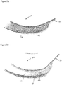
- Figure 2A shows a standard curved Macintosh blade (4a) comprising a sleeve (5a) configured to surround, partially or completely, the blade holding element (3) and having a proximal end and a distal end. The distal end of the sleeve preferably comprises a transparent window (6a).
- the blade (4a) further comprises a distal extension (7a) generally following the curve of the sleeve (5a).
- FIG. 2B shows a blade (4b) with an enhanced longitudinal circumference.
- This type of blade also referred to herein after as a "difficult blade" facilitates a view of the laryngeal inlet and is used for difficult and complex intubations.
- the blade (4b) comprises a sleeve (5b) configured to surround, partially or completely, the blade holding element (3) and having a proximal end and a distal end.
- the distal end of the sleeve preferably comprises a transparent window (6b).
- the blade (4b) further comprises a distal extension (7b) is displaced ventrally from the curve of the sleeve (5b).
- the difficult blade preferably comprises a guiding means for guiding the endotracheal tube into the correct position in the patient's airway.
- the guiding device comprises a paddle extending from the distal end of the sleeve (5b) and following the curve of the sleeve to direct the tube towards the tip of the distal extension (7b).
- the difficult blade (4b) is recommended for difficult and complex intubations and standard Macintosh blades (4a) are used in most straightforward intubations.
- the standard blades (a) have the advantages of being generally cheaper than the difficult blades (4b).
- the difficult blades (4b) can lead to laryngeal injury when unnecessarily used for a simple straightforward intubation case. There is therefore a need for both types of blade and the clinician will choose the most appropriate blade for the situation.
- the laryngoscope system (1) further comprises means for viewing the laryngeal inlet of a patient.
- Such means can comprise a display screen (not shown) to visualise the area captured, for example, by a camera.
- a detachable or fixed display screen may be connected at the proximal end of the handle (2) or a separate display screen may be provided.
- the viewing means includes at least one camera element (9) which is located at the distal end of the blade holding element (3) so as to be directed towards the distal end of the blade (4).
- the image captured by the camera may be transferred to a display screen and/or other viewing means for example by means of fibre optic.
- the laryngoscope system (1) may also comprise a light source and/or any other visualisation means that enable external indirect visualisation of the laryngeal inlet.
- a light source may be provided so that the distal tip of the blade is illuminated.
- the laryngoscope (1) is inserted into the mouth of the patient.
- the blade (4) will push the tongue of the patient to the side of the oropharynx to create space through which the larynx and the epiglottis can be viewed.
- the blade (4) is manipulated to lift the epiglottis thereby exposing the laryngeal inlet.
- An endotracheal tube can then be introduced and advanced past the vocal cords into the trachea.
- the endotracheal tube can be inserted together with the laryngoscope so that the tube-laryngoscope are inserted and positioned at the same time.
- the laryngoscope may be inserted first and the tube may be inserted after the laryngoscope is in the correct position.
- the user can visualise the distal end of the blade (4) for example on the display screen and manipulate the laryngoscope (1) accordingly. Once the tube is correctly positioned, the laryngoscope (1) is removed.
- the main problem solved by the present invention is the adjustment of the viewing field so that the clinician has a clear view of the laryngeal inlet of the patient, with minimum distortion and maximum focus, regardless of the type of blade fitted onto the blade holding element.
- the viewing field covers at least a 30° viewing angle below the tip of the extension (7) for optimum view of the laryngeal inlet. This area cannot be clearly viewed for example when a prior art laryngoscope configured for use with a standard blade is used with a difficult blade, because the view is obstructed by the tracheal tube guiding means and/or because of the ventral displacement of the distal extension of the blade.
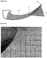
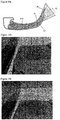
- Figure 3 shows part of a laryngoscope system according to a first embodiment of the invention, in which the outer contour of the blade holding element (3) corresponds substantially to the inner shape of the sleeves (5a, 5b) of the standard and difficult blades (4a, 4b) so that the blades can be used interchangeably with the same laryngoscope.
- the fixed camera element (9) is located at the distal end of the blade holding element (3).
- the blade holding element (3) is fitted with a short standard curved blade and with a long standard curved blade (4a), respectively.
- Line H-H passes between the centre of the lens of the camera (9) and the pivotal joint between the handle (2) and the blade holding element (3).
- the camera (9) is arranged so that the centre of the visual field captured by the camera is located at an angle ⁇ 1 ranging for example from 5° to 15° from line H-H in the plan defined by line H-H and the longitudinal axis of the handle (2).
- the exemplary angle is 12.75° and there is minimum blade intrusion into the view frame.
- the views captured by the camera (9) are shown in figures 4b and 5b .
- the views are clear and not distorted (as illustrated by the perfectly square grid). These are satisfactory views but ideally the tip of the distal extension (7a) should be visible so that the view is precisely focused on the laryngeal inlet of the patient.
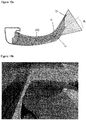
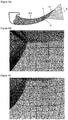
- the blade holding element (3) is fitted with a difficult blade (4b).
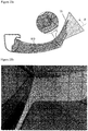
- the distal end of the sleeve (6b) comprises a wedge prism that redirects the optical pathway so that the tip of the extension (7b), and therefore the laryngeal inlet of the patient, is visible as shown in figure 6b .
- the prism is chosen so that the centre of the visual field captured by the camera is located for example at an angle ranging from 20° to 40°.
- the exemplary strength of the prism is 29° which provides an exemplary angle of 35.75° (corresponding to the original angle ⁇ 1 of 12.75° plus a ventral tilt ⁇ 1 of 23°).
- the view captured by the camera (9) is slightly distorted as can be seen by the compressed grid lines on figure 6b .
- the laryngoscope can be used with interchangeable blades.
- no prism is required since a satisfactory view is obtained using a strategic positioning of the camera.
- the clinician replaces the standard curved blade with a difficult blade fitted with a prism as described above to adjust the view so that a clear, non-distorted view of the laryngeal inlet is obtained.
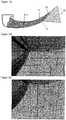
- Figure 7 shows part of a laryngoscope system according to a second embodiment of the invention.
- the main difference with the laryngoscope system of figure 3 lies in the position of the camera (9).
- the camera (9) is arranged so that the centre of the visual field captured by the camera is located at an angle ⁇ 2 ranging for example from 15° to 25° from line H-H in the plan defined by line H-H and the longitudinal axis of the handle (2).
- the angle ⁇ 2 is greater than ⁇ 1 (for example 17°)
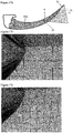
- the blade holding element (3) is fitted with a short standard curved blade and with a long standard curved blade (4a), respectively.
- the views captured by the camera (9) are shown in figures 8b and 9b and include the tip of the extension (7a).
- the views are clear and not distorted (as illustrated by the perfectly square grid). These are satisfactory views that, when positioned in the patient, precisely focus on the laryngeal inlet of the patient.
- the blade holding element (3) is fitted with a difficult blade (4b).
- the distal end of the sleeve (6b) comprises a wedge prism that redirects the optical pathway so that the tip of the extension (7b) is visible as shown in figure 10b .
- the prism is chosen so that the centre of the visual field captured by the camera is located for example at an angle ranging from 30° to 45°.
- the exemplary strength of the prism is 25° which provides an exemplary angle of 37° (corresponding to the original angle ⁇ 2 of 17° plus a ventral tilt ⁇ 2 of 20°).
- the view captured by the camera (9) is less distorted and clearer than that obtained with the stronger wedge prism of the first embodiment (see figure 6b ).
- Figure 11 shows part of a laryngoscope system according to a third embodiment of the invention.
- the camera (9) is arranged so that the centre of the visual field captured by the camera is located at an angle ⁇ 3 ranging for example from 25° to 40° from line H-H in the plan defined by line H-H and the longitudinal axis of the handle (2).
- the angle ⁇ 3 is greater than ⁇ 1 and ⁇ 2 (for example 32°).
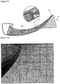
- the blade holding element (3) is fitted with a short standard curved blade and with a long standard curved blade (4a), respectively.
- a wedge prism is fitted at the distal end of the sleeve (6a) to direct the viewing field towards the tip of the extension (7a).
- Figures 12b and 13b show the views obtained using the blades of figures 12a and 13a and the re-positioning of the camera on its own (i.e. without a wedge prism). No distortion is observed and the view is clear. However, the extension (7a) intrudes into (approximately 1/3 of) the viewing field.
- the tip of the extension is visible but does not substantially intrude into the viewing field. A slight distortion is observed but the view is sufficiently clear to allow inspection of the patient's airway to efficiently insert a tracheal tube.
- the exemplary strength of the prism is 20° which provides an exemplary angle of 18° corresponding to the original angle ⁇ 3 of 32° minus a dorsal tilt ⁇ 3 of 14°. In this case, the tilt ⁇ 3 is subtracted from the original angle ⁇ 3 because the wedge prism is positioned so that the view is re-adjusted dorsally and not ventrally (as in the previous embodiments).
- the blade holding element (3) is fitted with a difficult blade (4b).
- the exemplary strength of the prism is 20° which provides an exemplary angle of 46° corresponding to the original angle ⁇ 3 of 32° due to the positioning of the camera, plus a ventral tilt ⁇ 3 of 14° due to the presence of the prism.
- a clear view with significantly reduced distortion is obtained as can be seen in figure 14c .
- figure 14b shows a view obtained using the blade of figures 14a and the re-positioning of the camera on its own (i.e. without a wedge prism). No distortion is observed and the view is clear but the tip of the extension (7b) is not visible, i.e. the view is not precisely focused on the laryngeal inlet of the patient.
- the laryngoscope system of figure 15 is similar to that shown in figure 11 .
- the difference is that the camera (9) is arranged so that the centre of the visual field captured by the camera is located at an angle ⁇ 4 of for example 27.5° from line H-H in the plan defined by line H-H and the longitudinal axis of the handle (2).
- the blade holding element (3) is fitted with a short standard curved blade and with a long standard curved blade (4a), respectively.
- the wedge prism is weaker than that used in embodiment 3, for example with a strength of 16° and the resulting angle is 18° corresponding to the original angle ⁇ 4 of 27.5° due to the positioning of the camera, minus a dorsal tilt ⁇ 4 of 9.5° due to the presence of the prism.
- the extension (7a) intrudes into the viewing field when the blade (4a) is not fitted with a wedge prism, but the view is clear and non-distorted.
- the prism is fitted to the distal end of the sleeve (5a) of the blade (4a)
- only the tip of the extension (7a) is visible, thereby indicating that a focused view of the laryngeal inlet can be obtained (see figures 16c and 17c ).
- the blade holding element (3) is fitted with a difficult blade (4b).
- the exemplary strength of the prism is 21.5° which provides an exemplary angle of 45° corresponding to the original angle ⁇ 4 of 27.5° due to the positioning of the camera, plus a ventral tilt ⁇ 4 of 17.5° due to the presence of the prism.
- a clear view with significantly reduced distortion is obtained as can be seen in figure 18c .
- figure 18b shows a view obtained using the blade of figures 18a and the re-positioning of the camera on its own (i.e. without a wedge prism). No distortion is observed and the view is clear but the tip of the extension (7b) is not visible.
- the distal end of the blade holding element (3) may be fitted with at least a first and a second camera (9).
- the first camera may be positioned so that a clear, non-distorted view of the laryngeal inlet is obtained when using a standard blade and the second camera may be positioned so that a clear, non-distorted view of the laryngeal inlet is obtained when using a difficult blade.
- a laryngoscope fitted with such a viewing means enables the clinician to use one laryngoscope for at least standard and difficult blades, thereby limiting expenses.
- this type of laryngoscope may be used with blades which do not require a prism or any other means of adjusting the viewing field, since the viewing field is already adjusted using a multi-camera system.
- the laryngoscope system (1) may further comprise means (for example electronic means) for switching from one camera to the other so that the clinician may select to use the first and/or the second camera depending on the view required and the type of blade fitted onto the blade holding element.
- means for example electronic means for switching from one camera to the other so that the clinician may select to use the first and/or the second camera depending on the view required and the type of blade fitted onto the blade holding element.
- the inventors further developed the laryngoscope system of Embodiment 5 by replacing the multi-camera system with a single movable or "tiltable" camera (9) fitted at the distal end of the blade holding element (3).
- the camera may be encased in a low friction housing, it may be fitted with a mechanical or electronic means of tilting the camera so that the viewing field is focused on the laryngeal inlet of the patient.
- This type of laryngoscope system may be used with blades which do not require any prism or any other means of adjusting the viewing field.
- the laryngoscope system (1) may further comprise means for positioning the camera in the desired position so that a clear, non-distorted view of the laryngeal inlet.
- the laryngoscope system may comprise mechanical or electronic means for remotely changing the position of the camera.
- the blades may be such that the position of the camera is automatically adjusted when the blade is fitted onto the blade holding element.
- the distal end (6) of the sleeve (5) may be built or moulded at an angle so that upon fitting the blade onto the blade holding element, the distal end or window (6) pushes the camera into a position suitable for viewing the tip of the extension (7) of the blade in a clear and non-distorted manner.
- Such constructions are shown in figures 20a , 21a and 22a and the corresponding views are shown in figures 20b , 21b and 22b .
- the prism may be fitted onto the blade by any suitable means, including for example screws and/or glue.
- the prism is integrally moulded at the distal end of the sleeve.
- An integrally mounted prism has the advantage of being less expensive, more robust and less prone to contamination.
Description
- This application relates to a laryngoscope system and more particularly to a video laryngoscope system.
- Whereas a conventional laryngoscope is used by a physician to visualise the path to the trachea by manipulating the patient's anatomy to establish a direct line of sight, a video laryngoscope provides a view of the glottis and trachea without the need for such manipulation, which is clearly advantageous.
- In recent times video laryngoscopes have also been provided that have removable, disposable blades, to remove the need for sterilisation. Such a laryngoscope is disclosed in
US2003181789 A1 . - A laryngoscope is a device which is used by clinicians during tracheal intubation and that assists with intubation by allowing the clinician to visualise the path of the endotracheal tube as it passes through the glottis towards the trachea. In its most recent form a laryngoscope comprises a handle and a blade and often includes a light source. Some laryngoscopes are also provided with viewing devices such as fibre optics and cameras. These are called video laryngoscopes.
- Most intubations are straightforward and clinicians use a laryngoscope with a straight or curved blade which is positioned into the patient's airway. However, some patients are known to be difficult to intubate, especially if there are anatomical abnormalities (e.g. if the larynx lies particularly anteriorly) or if there are injuries. Intubation of these patients is more successful using a blade with a different shape, such as the "difficult blade" described in more detail below. A blade for use in difficult intubations preferably has a curved portion that smoothly follows the anatomical shape of the patient's airways, a ventrally displaced distal extension to allow a better view of the laryngeal inlet and a paddle to guide the endotracheal tube towards the laryngeal inlet.
- There is currently no universal blade that can be used in all cases and a number of different blades may be desired and beneficial so that the clinician can visualise the laryngeal inlet with a choice of blade shapes depending upon clinical requirements and personal expertise and preference. Since existing video laryngoscopes are necessarily used with one compatible blade shape, the user will need to use an entirely different laryngoscope depending on the situation. For example, a clinician could insert a video laryngoscope with a standard curved blade into a patient and upon insertion realise that abnormalities are present which require a modified blade. He or she would then need a second video laryngoscope with a modified blade to visualise the laryngeal inlet, thereby adding to the cost of the equipment required to perform efficiently. The blades are often disposable and relatively cheap, whereas the handle comprising the viewing means is generally expensive. There is therefore a need for a laryngoscope which may be used with different blade shapes.
- It is an object of this invention to seek to mitigate problems such as those described above.
- According to a first aspect of the invention, there is provided a laryngoscope system comprising a handle, a blade holding element, and means for viewing the laryngeal inlet of a patient, the viewing means comprising at least one fixed camera located at the distal end of the blade holding element, characterised in that the system further comprises at least two detachable blades, wherein at least one of the at least two detachable blades is a standard blade for performing standard intubations, wherein the standard blade comprises a sleeve configured to surround, partially or completely, the blade holding element, a proximal end and a distal end, wherein the distal end of the sleeve comprises a transparent window, and a distal tip extension, wherein the distal tip extension follows the curve of the sleeve, wherein at least one other of the at least two detachable blades is a difficult blade for performing difficult intubations comprising an enhanced longitudinal circumference, a sleeve configured to surround, partially or completely, the blade holding element, a proximal end and a distal end, wherein the distal end of the sleeve comprises a transparent window, and a distal tip extension, wherein the distal tip extension is displaced ventrally from the curve of the sleeve, the difficult blade further comprising a wedge prism at the distal end of the sleeve for adjusting the viewing field, wherein the wedge prism redirects an optical pathway so that the distal tip extension and therefore the laryngeal inlet of a patient is visible.
- The detachable blades may further comprise means for guiding the endotracheal tube towards the tip of the distal extension. This is particularly useful where the clinician faces a difficult and complex intubation situation.
- In another preferred embodiment, the viewing means comprises at least two fixed cameras elements directed to at least two different viewing fields. Preferably, the laryngoscope system further comprises means for switching from one camera to the other so that for example the first camera is used for when the laryngoscope system is fitted with a standard blade and the second camera when a difficult blade is used.
- In yet another embodiment, the viewing means comprises a movable camera element. Preferably, the laryngoscope system further comprises mechanical or electronic means for controlling the movement of the camera. For example, the distal end of the sleeve of the blade may comprise a window positioned such that, in use, the camera is positioned to visualise the laryngeal inlet of the patient.
- The invention will be further described with reference to the drawings, in which:
-
Figure 1A to 1C show a laryngoscope system according to the invention; -
Figure 2A shows a standard curved blade; -
Figure 2B shows a blade for difficult intubations; -
Figure 3 shows part of a laryngoscope system according to a first embodiment of the invention; -
Figure 4a shows the laryngoscope system offigure 3 fitted with a short standard curved blade; -
Figure 4b shows a view obtained with the laryngoscope system offigure 4a ; -
Figure 5a shows the laryngoscope system offigure 3 fitted with a long standard curved blade; -
Figure 5b shows a view obtained with the laryngoscope system offigure 5a ; -
Figure 6a shows the laryngoscope system offigure 3 fitted with a difficult blade; -
Figure 6b shows a view obtained with the laryngoscope system offigure 6a ; -
Figure 7 shows part of a laryngoscope system according to a second embodiment of the invention; -
Figure 8a shows the laryngoscope system offigure 7 fitted with a short standard curved blade; -
Figure 8b shows a view obtained with the laryngoscope system offigure 8a ; -
Figure 9a shows the laryngoscope system offigure 7 fitted with a long standard curved blade; -
Figure 9b shows a view obtained with the laryngoscope system offigure 9a ; -
Figure 10a shows the laryngoscope system offigure 7 fitted with a difficult blade; -
Figure 10b shows a view obtained with the laryngoscope system offigure 10a ; -
Figure 11 shows part of a laryngoscope system according to a third embodiment of the invention; -
Figure 12a shows the laryngoscope system offigure 11 fitted with a short standard curved blade; -
Figure 12b shows a view obtained with the laryngoscope system offigure 12a without a prism; -
Figure 12c shows a view obtained with the laryngoscope system offigure 12a with a prism; -
Figure 13a shows the laryngoscope system offigure 11 fitted with a short standard curved blade; -
Figure 13b shows a view obtained with the laryngoscope system offigure 13a without a prism; -
Figure 13c shows a view obtained with the laryngoscope system offigure 13a with a prism; -
Figure 14a shows the laryngoscope system offigure 11 fitted with a short standard curved blade; -
Figure 14b shows a view obtained with the laryngoscope system offigure 14a without a prism; -
Figure 14c shows a view obtained with the laryngoscope system offigure 14a with a prism; -
Figure 15 shows part of a laryngoscope system according to a fourth embodiment of the invention; -
Figure 16a shows the laryngoscope system offigure 11 fitted with a short standard curved blade;Figure 16b shows a view obtained with the laryngoscope system offigure 16a without a prism; -
Figure 16c shows a view obtained with the laryngoscope system offigure 16a with a prism; -
Figure 17a shows the laryngoscope system offigure 11 fitted with a short standard curved blade; -
Figure 17b shows a view obtained with the laryngoscope system offigure 17a without a prism; -
Figure 17c shows a view obtained with the laryngoscope system offigure 17a with a prism; -
Figure 18a shows the laryngoscope system offigure 11 fitted with a short standard curved blade; -
Figure 18b shows a view obtained with the laryngoscope system offigure 18a without a prism; -
Figure 18c shows a view obtained with the laryngoscope system offigure 18a with a prism; -
Figure 19 shows part of a laryngoscope system according to a second embodiment of the invention; -
Figure 20a shows the laryngoscope system offigure 9 fitted with a short standard curved blade; -
Figure 20b shows a view obtained with the laryngoscope system offigure 20a ; -
Figure 21a shows the laryngoscope system offigure 9 fitted with a long standard curved blade; -
Figure 21b shows a view obtained with the laryngoscope system offigure 20a ; -
Figure 22a shows the laryngoscope system offigure 9 fitted with a difficult blade; and -
Figure 22b shows a view obtained with the laryngoscope system offigure 20a ; - In this application, the terms "distal part" and "proximal part" are used relative to the medical professional, i.e. the "distal part" is used to describe the part of the device that is inserted first into the patient. The terms "dorsal" and "ventral" are used relative to the patient, i.e. the "dorsal" side is used to describe the side directed to the back of the patient and the "ventral" side is used to describe the side directed to the front of the patient.
- With reference to
figures 1A to 1C , the laryngoscope system (1) comprises a handle (2) for holding and manoeuvring the laryngoscope, a blade holding element (3) that is pivotally attached to the handle (2) and a detachable blade (4) that is attached the blade holding element (3). - The handle (2) is preferably made of stainless steel for robustness, although other materials such as metals or plastics may be used. At the proximal end, the blade holding element (3) is pivotally connected to the heel of the handle (2). The blade (4) is preferably hollow so that it can be fitted onto the blade holding element by sliding as can be seen in
figures 1A-1C (described in more detail below). Preferably, the blade holding element (3) is elongated in shape and its outer contour corresponds substantially to the inner shape of the blade (4). - The blade (4) is preferably integrally constructed and is for example produced by injection moulding so that the cost of production is relatively affordable. The blade is preferably disposable to minimise or eliminate any risk of cross-contamination between patients. The blade may be made partially or completely with a transparent material in order to view the areas surrounding the laryngeal inlet.
- The blade (4) may be straight (e.g. a Miller laryngoscope blade), curved (e.g. a Macintosh blade). Curved blades are generally preferred by clinicians because they are dimensioned to conform to the anatomical curve of the patient's throat.
Figure 2A shows a standard curved Macintosh blade (4a) comprising a sleeve (5a) configured to surround, partially or completely, the blade holding element (3) and having a proximal end and a distal end. The distal end of the sleeve preferably comprises a transparent window (6a). The blade (4a) further comprises a distal extension (7a) generally following the curve of the sleeve (5a). -
Figure 2B shows a blade (4b) with an enhanced longitudinal circumference. This type of blade (also referred to herein after as a "difficult blade") facilitates a view of the laryngeal inlet and is used for difficult and complex intubations. - The blade (4b) comprises a sleeve (5b) configured to surround, partially or completely, the blade holding element (3) and having a proximal end and a distal end. The distal end of the sleeve preferably comprises a transparent window (6b). The blade (4b) further comprises a distal extension (7b) is displaced ventrally from the curve of the sleeve (5b).
- The difficult blade preferably comprises a guiding means for guiding the endotracheal tube into the correct position in the patient's airway. In the blade (4b) shown in
figure 2B , the guiding device comprises a paddle extending from the distal end of the sleeve (5b) and following the curve of the sleeve to direct the tube towards the tip of the distal extension (7b). - As mentioned above, the difficult blade (4b) is recommended for difficult and complex intubations and standard Macintosh blades (4a) are used in most straightforward intubations. The standard blades (a) have the advantages of being generally cheaper than the difficult blades (4b). In addition, the difficult blades (4b) can lead to laryngeal injury when unnecessarily used for a simple straightforward intubation case. There is therefore a need for both types of blade and the clinician will choose the most appropriate blade for the situation.
- The laryngoscope system (1) further comprises means for viewing the laryngeal inlet of a patient. Such means can comprise a display screen (not shown) to visualise the area captured, for example, by a camera. A detachable or fixed display screen may be connected at the proximal end of the handle (2) or a separate display screen may be provided. An advantage of having a detachable screen is that the equipment can be easily cleaned after use.
- The viewing means includes at least one camera element (9) which is located at the distal end of the blade holding element (3) so as to be directed towards the distal end of the blade (4). The image captured by the camera may be transferred to a display screen and/or other viewing means for example by means of fibre optic.
- The laryngoscope system (1) may also comprise a light source and/or any other visualisation means that enable external indirect visualisation of the laryngeal inlet. For example, a light source may be provided so that the distal tip of the blade is illuminated.
- In operation, the laryngoscope (1) is inserted into the mouth of the patient. The blade (4) will push the tongue of the patient to the side of the oropharynx to create space through which the larynx and the epiglottis can be viewed. The blade (4) is manipulated to lift the epiglottis thereby exposing the laryngeal inlet.
- An endotracheal tube can then be introduced and advanced past the vocal cords into the trachea. The endotracheal tube can be inserted together with the laryngoscope so that the tube-laryngoscope are inserted and positioned at the same time. Alternatively, the laryngoscope may be inserted first and the tube may be inserted after the laryngoscope is in the correct position. The user can visualise the distal end of the blade (4) for example on the display screen and manipulate the laryngoscope (1) accordingly. Once the tube is correctly positioned, the laryngoscope (1) is removed.
- The main problem solved by the present invention is the adjustment of the viewing field so that the clinician has a clear view of the laryngeal inlet of the patient, with minimum distortion and maximum focus, regardless of the type of blade fitted onto the blade holding element. Preferably, the viewing field covers at least a 30° viewing angle below the tip of the extension (7) for optimum view of the laryngeal inlet. This area cannot be clearly viewed for example when a prior art laryngoscope configured for use with a standard blade is used with a difficult blade, because the view is obstructed by the tracheal tube guiding means and/or because of the ventral displacement of the distal extension of the blade.
-
Figure 3 shows part of a laryngoscope system according to a first embodiment of the invention, in which the outer contour of the blade holding element (3) corresponds substantially to the inner shape of the sleeves (5a, 5b) of the standard and difficult blades (4a, 4b) so that the blades can be used interchangeably with the same laryngoscope. The fixed camera element (9) is located at the distal end of the blade holding element (3). - In
figures 4a and5a , the blade holding element (3) is fitted with a short standard curved blade and with a long standard curved blade (4a), respectively. Line H-H passes between the centre of the lens of the camera (9) and the pivotal joint between the handle (2) and the blade holding element (3). The camera (9) is arranged so that the centre of the visual field captured by the camera is located at an angle α1 ranging for example from 5° to 15° from line H-H in the plan defined by line H-H and the longitudinal axis of the handle (2). Infigures 4a and5a , the exemplary angle is 12.75° and there is minimum blade intrusion into the view frame. - The views captured by the camera (9) are shown in
figures 4b and5b . The views are clear and not distorted (as illustrated by the perfectly square grid). These are satisfactory views but ideally the tip of the distal extension (7a) should be visible so that the view is precisely focused on the laryngeal inlet of the patient. - In
figure 6a , the blade holding element (3) is fitted with a difficult blade (4b). The distal end of the sleeve (6b) comprises a wedge prism that redirects the optical pathway so that the tip of the extension (7b), and therefore the laryngeal inlet of the patient, is visible as shown infigure 6b . Preferably, the prism is chosen so that the centre of the visual field captured by the camera is located for example at an angle ranging from 20° to 40°. Infigure 6b , the exemplary strength of the prism is 29° which provides an exemplary angle of 35.75° (corresponding to the original angle α1 of 12.75° plus a ventral tilt β1 of 23°). However, the view captured by the camera (9) is slightly distorted as can be seen by the compressed grid lines onfigure 6b . - In this first embodiment, the laryngoscope can be used with interchangeable blades. When fitted with a standard curved blade, no prism is required since a satisfactory view is obtained using a strategic positioning of the camera. For difficult intubations, the clinician replaces the standard curved blade with a difficult blade fitted with a prism as described above to adjust the view so that a clear, non-distorted view of the laryngeal inlet is obtained.
-
Figure 7 shows part of a laryngoscope system according to a second embodiment of the invention. The main difference with the laryngoscope system offigure 3 lies in the position of the camera (9). The camera (9) is arranged so that the centre of the visual field captured by the camera is located at an angle α2 ranging for example from 15° to 25° from line H-H in the plan defined by line H-H and the longitudinal axis of the handle (2). The angle α2 is greater than α1 (for example 17°) - In
figures 8a and9a , the blade holding element (3) is fitted with a short standard curved blade and with a long standard curved blade (4a), respectively. The views captured by the camera (9) are shown infigures 8b and9b and include the tip of the extension (7a). The views are clear and not distorted (as illustrated by the perfectly square grid). These are satisfactory views that, when positioned in the patient, precisely focus on the laryngeal inlet of the patient. - In
figure 10a , the blade holding element (3) is fitted with a difficult blade (4b). The distal end of the sleeve (6b) comprises a wedge prism that redirects the optical pathway so that the tip of the extension (7b) is visible as shown infigure 10b . Preferably, the prism is chosen so that the centre of the visual field captured by the camera is located for example at an angle ranging from 30° to 45°. Infigure 6b , the exemplary strength of the prism is 25° which provides an exemplary angle of 37° (corresponding to the original angle α2 of 17° plus a ventral tilt β2 of 20°). The view captured by the camera (9) is less distorted and clearer than that obtained with the stronger wedge prism of the first embodiment (seefigure 6b ). -
Figure 11 shows part of a laryngoscope system according to a third embodiment of the invention. The camera (9) is arranged so that the centre of the visual field captured by the camera is located at an angle α3 ranging for example from 25° to 40° from line H-H in the plan defined by line H-H and the longitudinal axis of the handle (2). The angle α3 is greater than α1 and α2 (for example 32°). - In
figures 12a and13a , the blade holding element (3) is fitted with a short standard curved blade and with a long standard curved blade (4a), respectively. In addition, a wedge prism is fitted at the distal end of the sleeve (6a) to direct the viewing field towards the tip of the extension (7a). -
Figures 12b and13b show the views obtained using the blades offigures 12a and13a and the re-positioning of the camera on its own (i.e. without a wedge prism). No distortion is observed and the view is clear. However, the extension (7a) intrudes into (approximately 1/3 of) the viewing field. - By contrast, when a wedge prism is fitted onto the blade (see
figures 12c and13c ), the tip of the extension is visible but does not substantially intrude into the viewing field. A slight distortion is observed but the view is sufficiently clear to allow inspection of the patient's airway to efficiently insert a tracheal tube. Infigures 12a and13a , the exemplary strength of the prism is 20° which provides an exemplary angle of 18° corresponding to the original angle α3 of 32° minus a dorsal tilt β3 of 14°. In this case, the tilt β3 is subtracted from the original angle α3 because the wedge prism is positioned so that the view is re-adjusted dorsally and not ventrally (as in the previous embodiments). - In
figure 14a , the blade holding element (3) is fitted with a difficult blade (4b). The exemplary strength of the prism is 20° which provides an exemplary angle of 46° corresponding to the original angle α3 of 32° due to the positioning of the camera, plus a ventral tilt β3 of 14° due to the presence of the prism. A clear view with significantly reduced distortion is obtained as can be seen infigure 14c . - As a comparison,
figure 14b shows a view obtained using the blade offigures 14a and the re-positioning of the camera on its own (i.e. without a wedge prism). No distortion is observed and the view is clear but the tip of the extension (7b) is not visible, i.e. the view is not precisely focused on the laryngeal inlet of the patient. - The laryngoscope system of
figure 15 is similar to that shown infigure 11 . The difference is that the camera (9) is arranged so that the centre of the visual field captured by the camera is located at an angle α4 of for example 27.5° from line H-H in the plan defined by line H-H and the longitudinal axis of the handle (2). - In
figures 16a and17a , the blade holding element (3) is fitted with a short standard curved blade and with a long standard curved blade (4a), respectively. The wedge prism is weaker than that used inembodiment 3, for example with a strength of 16° and the resulting angle is 18° corresponding to the original angle α4 of 27.5° due to the positioning of the camera, minus a dorsal tilt β4 of 9.5° due to the presence of the prism. - As can be seen on
figures 16b and17b , the extension (7a) intrudes into the viewing field when the blade (4a) is not fitted with a wedge prism, but the view is clear and non-distorted. When the prism is fitted to the distal end of the sleeve (5a) of the blade (4a), then only the tip of the extension (7a) is visible, thereby indicating that a focused view of the laryngeal inlet can be obtained (seefigures 16c and17c ). There is little distortion and the view is clear. - In
figure 18a , the blade holding element (3) is fitted with a difficult blade (4b). The exemplary strength of the prism is 21.5° which provides an exemplary angle of 45° corresponding to the original angle α4 of 27.5° due to the positioning of the camera, plus a ventral tilt β4 of 17.5° due to the presence of the prism. A clear view with significantly reduced distortion is obtained as can be seen infigure 18c . - As a comparison,
figure 18b shows a view obtained using the blade offigures 18a and the re-positioning of the camera on its own (i.e. without a wedge prism). No distortion is observed and the view is clear but the tip of the extension (7b) is not visible. - The distal end of the blade holding element (3) may be fitted with at least a first and a second camera (9). The first camera may be positioned so that a clear, non-distorted view of the laryngeal inlet is obtained when using a standard blade and the second camera may be positioned so that a clear, non-distorted view of the laryngeal inlet is obtained when using a difficult blade. A laryngoscope fitted with such a viewing means enables the clinician to use one laryngoscope for at least standard and difficult blades, thereby limiting expenses. In addition, this type of laryngoscope may be used with blades which do not require a prism or any other means of adjusting the viewing field, since the viewing field is already adjusted using a multi-camera system.
- The laryngoscope system (1) may further comprise means (for example electronic means) for switching from one camera to the other so that the clinician may select to use the first and/or the second camera depending on the view required and the type of blade fitted onto the blade holding element.
- The inventors further developed the laryngoscope system of Embodiment 5 by replacing the multi-camera system with a single movable or "tiltable" camera (9) fitted at the distal end of the blade holding element (3). For example, the camera may be encased in a low friction housing, it may be fitted with a mechanical or electronic means of tilting the camera so that the viewing field is focused on the laryngeal inlet of the patient. This type of laryngoscope system may be used with blades which do not require any prism or any other means of adjusting the viewing field.
- The laryngoscope system (1) may further comprise means for positioning the camera in the desired position so that a clear, non-distorted view of the laryngeal inlet. For example, the laryngoscope system may comprise mechanical or electronic means for remotely changing the position of the camera. Alternatively, the blades may be such that the position of the camera is automatically adjusted when the blade is fitted onto the blade holding element. For example, the distal end (6) of the sleeve (5) may be built or moulded at an angle so that upon fitting the blade onto the blade holding element, the distal end or window (6) pushes the camera into a position suitable for viewing the tip of the extension (7) of the blade in a clear and non-distorted manner. Such constructions are shown in
figures 20a ,21a and22a and the corresponding views are shown infigures 20b ,21b and22b . - Where the blade comprises a wedge prism, the prism may be fitted onto the blade by any suitable means, including for example screws and/or glue. Preferably, the prism is integrally moulded at the distal end of the sleeve. An integrally mounted prism has the advantage of being less expensive, more robust and less prone to contamination.
- It is believed that currently more than 95% of all intubations can be carried out using a standard blade, which means that clinicians need to buy a laryngoscope, specifically designed for use with a difficult blade, for the remaining 5% (or less) of the intubations. The laryngoscope system described above enables clinicians to minimise expenses because only one universal laryngoscope system is required for use with physically and functionally dissimilar blades. In addition, the different types of blade may be used interchangeably without substantially compromising the clarity of the view of the patient's laryngeal inlet.
Claims (7)
- A laryngoscope system (1) comprising a handle (2), a blade holding element (3), and means for viewing the laryngeal inlet of a patient, the viewing means comprising at least one fixed camera (9) located at the distal end of the blade holding element (3), the system further comprises at least two detachable blades (4a, 4b), wherein at least one of the at least two detachable blades (4a, 4b) is a standard blade for performing standard intubations, wherein the standard blade comprises a sleeve configured to surround, partially or completely, the blade holding element (3), a proximal end and a distal end, wherein the distal end of the sleeve comprises a transparent window, and a distal tip extension, wherein the distal tip extension follows the curve of the sleeve, wherein at least one other of the at least two detachable blades is a difficult blade for performing difficult intubations comprising an enhanced longitudinal circumference, a sleeve configured to surround, partially or completely, the blade holding element (3), a proximal end and a distal end, wherein the distal end of the sleeve comprises a transparent window, and a distal tip extension, wherein the distal tip extension is displaced ventrally from the curve of the sleeve, the difficult blade further comprising a wedge prism at the distal end of the sleeve for adjusting the viewing field, wherein the wedge prism redirects an optical pathway so that the distal tip extension and therefore the laryngeal inlet of a patient is visible.
- The laryngoscope (1) according to claim 1, wherein the detachable blade (4, 4a, 4b) further comprises means for guiding the endotracheal tube towards the tip of the distal extension (7a, 7b).
- The laryngoscope (1) according to any one of claims 1 to 2, wherein the viewing means comprises at least two fixed cameras elements (9) directed to at least two different viewing fields.
- The laryngoscope (1) according to claim 3, further comprising means for switching from one camera (9) to the other.
- The laryngoscope (1) according to any one of claims 1 to 2, wherein the viewing means comprises a movable camera element (9).
- The laryngoscope (1) according to claim 5, further comprising mechanical or electronic means for controlling the movement of the camera (9).
- The laryngoscope (1) according to claim 5, wherein the distal end of the sleeve (5a, 5b) of the blade (4, 4a, 4b) comprises a window (6a, 6b) positioned such that, in use, the camera (9) is positioned to visualise the laryngeal inlet of the patient.
Applications Claiming Priority (2)
| Application Number | Priority Date | Filing Date | Title |
|---|---|---|---|
| GBGB0915107.7A GB0915107D0 (en) | 2009-08-28 | 2009-08-28 | Laryngoscope |
| PCT/GB2010/001535 WO2011023930A1 (en) | 2009-08-28 | 2010-08-12 | Laryngoscope |
Publications (2)
| Publication Number | Publication Date |
|---|---|
| EP2470059A1 EP2470059A1 (en) | 2012-07-04 |
| EP2470059B1 true EP2470059B1 (en) | 2019-05-22 |
Family
ID=41202902
Family Applications (1)
| Application Number | Title | Priority Date | Filing Date |
|---|---|---|---|
| EP10754963.6A Active EP2470059B1 (en) | 2009-08-28 | 2010-08-12 | Laryngoscope system |
Country Status (10)
| Country | Link |
|---|---|
| US (1) | US9332896B2 (en) |
| EP (1) | EP2470059B1 (en) |
| JP (2) | JP5650744B2 (en) |
| CN (1) | CN102573608B (en) |
| AU (2) | AU2010288342B2 (en) |
| BR (1) | BR112012004444A2 (en) |
| CA (1) | CA2772498C (en) |
| ES (1) | ES2741959T3 (en) |
| GB (1) | GB0915107D0 (en) |
| WO (1) | WO2011023930A1 (en) |
Families Citing this family (21)
| Publication number | Priority date | Publication date | Assignee | Title |
|---|---|---|---|---|
| US9084572B2 (en) | 2011-11-01 | 2015-07-21 | Michael J. Trakas | Collapsible laryngoscope |
| GB201119797D0 (en) * | 2011-11-16 | 2011-12-28 | Aircraft Medical Ltd | Laryngoscope and kit comprising laryngoscope and blades |
| US8287450B1 (en) * | 2011-11-22 | 2012-10-16 | He Kongyuan | Laryngoscope with easy switch-and-select 2-blades combination |
| CA2896266A1 (en) | 2012-12-26 | 2014-07-03 | Verathon Medical (Canada) Ulc | Video retractor |
| AU2014266805B2 (en) * | 2013-05-16 | 2017-06-15 | Truphatek International Ltd | Video laryngoscope systems |
| US20160250432A1 (en) * | 2013-10-10 | 2016-09-01 | Kumudhini HENDRIX | Method and apparatus for multi-camera intubation |
| CH710358A1 (en) * | 2014-11-12 | 2016-05-13 | Univ Zuerich | Flexible intubating laryngoscope. |
| WO2016090435A1 (en) | 2014-12-12 | 2016-06-16 | Airway Medical Innovations Pty Ltd | Intubation device |
| CN105212884A (en) * | 2015-11-03 | 2016-01-06 | 乌日娜 | There is the laryngoscope of the abandoning property laryngoscope blade of decontamination function |
| JP6698348B2 (en) * | 2015-12-28 | 2020-05-27 | スカラ株式会社 | Larynx camera unit and laryngeal camera set |
| JP7084684B2 (en) * | 2016-02-08 | 2022-06-15 | 宝来メデック株式会社 | Laryngeal camera |
| CN107348938A (en) * | 2017-07-21 | 2017-11-17 | 叶建光 | A kind of video laryngoscope with display switching key |
| JP2020049158A (en) * | 2018-09-28 | 2020-04-02 | スカラ株式会社 | Endoscope |
| KR102288863B1 (en) * | 2019-02-27 | 2021-08-11 | 케이지메디텍 주식회사 | Video laryngoscope system for emegency rescue and method of emergency rescue using the same |
| USD950054S1 (en) * | 2019-04-03 | 2022-04-26 | Flexicare (Group) Limited | Laryngoscope blade |
| USD950724S1 (en) * | 2019-04-03 | 2022-05-03 | Flexicare (Group) Limited | Laryngoscope blade |
| EP3854290A1 (en) | 2020-01-24 | 2021-07-28 | Universität Zürich | Tip light laryngoscope for trans-tissue illumination |
| USD930157S1 (en) * | 2020-02-07 | 2021-09-07 | Tien-Sheng Chen | Laryngoscope blade |
| USD940314S1 (en) * | 2020-06-16 | 2022-01-04 | Tien-Sheng Chen | Laryngoscope blade |
| US11206973B1 (en) | 2020-09-14 | 2021-12-28 | Kenneth Hiller | Laryngoscope |
| CN116942067B (en) * | 2023-06-19 | 2024-03-22 | 珠海微视医用科技有限公司 | Disposable blade laryngoscope and processing method thereof |
Citations (3)
| Publication number | Priority date | Publication date | Assignee | Title |
|---|---|---|---|---|
| GB2086732A (en) * | 1980-11-11 | 1982-05-19 | Avulunga Pty Ltd | Blade and prism for laryngoscope |
| US20040127770A1 (en) * | 2000-12-23 | 2004-07-01 | Mcgrath Matthew J.R. | Laryngoscope |
| WO2009019703A2 (en) * | 2007-08-07 | 2009-02-12 | Truphatek International Ltd | Laryngoscope apparatus with enhanced viewing capability |
Family Cites Families (51)
| Publication number | Priority date | Publication date | Assignee | Title |
|---|---|---|---|---|
| GB1121432A (en) | 1965-05-20 | 1968-07-24 | Longworth Scient Instr Company | Improvements relating to laryngoscopes |
| FR2381528A1 (en) | 1977-02-25 | 1978-09-22 | Gabail Maurice | Tongue depressor for medical intubation - has optic fibres providing concentrated illumination down groove for accurate placing of tube |
| US4337761A (en) * | 1979-11-28 | 1982-07-06 | Upsher Michael S | Laryngoscope |
| US4579108A (en) | 1983-03-07 | 1986-04-01 | Jack Bauman | Laryngoscope blade and disposable cover |
| US4574784A (en) | 1984-09-04 | 1986-03-11 | Soloway David J | Laryngoscope |
| WO1986005377A1 (en) | 1985-03-19 | 1986-09-25 | Sun William Y | Sterile disposable laryngoscope blade sheath |
| US4979499A (en) | 1985-03-19 | 1990-12-25 | Sun William Y | Sterile disposable linguiform laryngoscope blade sheath |
| JPS6499A (en) | 1987-03-17 | 1989-01-05 | Nippon Kayaku Co Ltd | 23-phenylsteroids and production thereof |
| US5381787A (en) | 1990-05-04 | 1995-01-17 | Bullard; James R. | Extendable and retractable laryngoscope |
| US5261392A (en) | 1992-04-03 | 1993-11-16 | Achi Corporation | Laryngoscope with interchangeable fiberoptic assembly |
| US5347995A (en) | 1993-03-25 | 1994-09-20 | Slater William M | Laryngoscope blade cover |
| US5349943A (en) * | 1993-08-24 | 1994-09-27 | Hennepin Faculty Associates | Mirror laryngoscope blade |
| JP3406090B2 (en) | 1994-10-19 | 2003-05-12 | オリンパス光学工業株式会社 | Endoscope device |
| US6427686B2 (en) | 1996-10-16 | 2002-08-06 | Augustine Medical, Inc. | Airway device with provision for coupling to an introducer |
| DE19734591C1 (en) | 1997-08-09 | 1999-06-17 | Ruesch Willy Ag | Laryngoscope |
| US6655377B2 (en) | 1997-12-01 | 2003-12-02 | Saturn Biomedical Systems Inc. | Intubation instrument |
| JP2000184607A (en) | 1998-12-14 | 2000-06-30 | Sony Corp | Battery device and electronic apparatus using the same |
| JP3345645B2 (en) * | 2000-06-20 | 2002-11-18 | 東京大学長 | Body cavity observation device |
| JP2002000732A (en) | 2000-06-26 | 2002-01-08 | Hiroshi Sehata | Auxiliary device for endotracheal intubation |
| JP2002065589A (en) * | 2000-08-30 | 2002-03-05 | Olympus Optical Co Ltd | Endoscope device |
| FR2837088B1 (en) | 2002-03-15 | 2005-03-25 | Vygon | PACKAGING FOR SINGLE-USE LARYNGOSCOPE BLADE, BLADE THUS PACKED AND USE THEREOF |
| US6840903B2 (en) * | 2002-03-21 | 2005-01-11 | Nuvista Technology Corporation | Laryngoscope with image sensor |
| ES2234387B1 (en) | 2003-02-24 | 2007-08-01 | Pedro Acha Gandarias | OPTICAL LIGHTING LINGING SCOPE WITH INCORPORATED FLUID EXTRACTION DEVICE. |
| EP2505125A1 (en) * | 2003-04-29 | 2012-10-03 | Aircraft Medical Limited | Laryngoscope with camera attachment |
| US20100081875A1 (en) * | 2003-07-15 | 2010-04-01 | EndoRobotics Inc. | Surgical Device For Minimal Access Surgery |
| US20050240081A1 (en) | 2004-04-22 | 2005-10-27 | The Cleveland Clinic Foundation | Laryngoscope blade |
| US8827899B2 (en) * | 2004-09-24 | 2014-09-09 | Vivid Medical, Inc. | Disposable endoscopic access device and portable display |
| US8858425B2 (en) * | 2004-09-24 | 2014-10-14 | Vivid Medical, Inc. | Disposable endoscope and portable display |
| US8602971B2 (en) * | 2004-09-24 | 2013-12-10 | Vivid Medical. Inc. | Opto-Electronic illumination and vision module for endoscopy |
| JP4814504B2 (en) | 2004-09-27 | 2011-11-16 | 淳一 小山 | Intubation support tool and intubation support device |
| CN2770570Y (en) | 2005-03-19 | 2006-04-12 | 周东贤 | Telescopic laryngoscope |
| US7740616B2 (en) | 2005-03-29 | 2010-06-22 | Angiodynamics, Inc. | Implantable catheter and method of using same |
| US8187180B2 (en) * | 2005-04-01 | 2012-05-29 | Verathon Medical (Canada) Ulc | Video rectractor |
| JP4738893B2 (en) * | 2005-05-27 | 2011-08-03 | 大研医器株式会社 | Laryngoscope |
| JP4761928B2 (en) * | 2005-10-24 | 2011-08-31 | Hoya株式会社 | Intubation support device |
| GB0525095D0 (en) | 2005-12-09 | 2006-01-18 | Aircraft Medical Ltd | Further improvements in and relating to light transmission in laryngoscope blades |
| WO2007066134A2 (en) | 2005-12-09 | 2007-06-14 | Aircraft Medical Limited | Laryngoscope blade |
| US20070175482A1 (en) * | 2006-01-27 | 2007-08-02 | Ezc Medical Llc | Apparatus for introducing an airway tube into the trachea having visualization capability and methods of use |
| CN2870731Y (en) | 2006-01-28 | 2007-02-21 | 滕永华 | Electronic adjustable throat mirrow |
| US20070287888A1 (en) | 2006-06-09 | 2007-12-13 | Dp Medical | Integrated laryngoscope and suction device |
| JP4963575B2 (en) | 2006-07-24 | 2012-06-27 | 株式会社ブリヂストン | Pneumatic tire |
| JP4621645B2 (en) | 2006-08-25 | 2011-01-26 | Okiセミコンダクタ株式会社 | Manufacturing method of semiconductor device |
| TWM309971U (en) * | 2006-09-13 | 2007-04-21 | Tien-Sheng Chen | Bronchoscope with wireless-transmission monitor |
| JP2008119305A (en) * | 2006-11-14 | 2008-05-29 | Michiro Ozaki | Laryngoscope and laryngoscope system |
| JP2008289669A (en) * | 2007-05-24 | 2008-12-04 | Michiro Ozaki | Laryngoscope and laryngoscope system |
| AU2008266236B2 (en) * | 2007-06-12 | 2012-04-12 | Avn Medical Technologies, Llc | Airway management |
| GB2452406B (en) | 2007-08-28 | 2010-03-17 | Aircraft Medical Ltd | Laryngoscope insertion section |
| US20090099421A1 (en) * | 2007-10-12 | 2009-04-16 | M.S.Vision Ltd | Intubation laryngoscope with a double holder |
| CN201194790Y (en) | 2008-04-28 | 2009-02-18 | 丁理 | Disassemble electronic video anaesthesia laryngoscope |
| US8317693B2 (en) * | 2008-08-13 | 2012-11-27 | Invuity, Inc. | Cyclo olefin polymer and copolymer medical devices |
| GB0819942D0 (en) | 2008-10-30 | 2008-12-10 | Indian Ocean Medical Inc | Guiding device for use with laryngoscope |
-
2009
- 2009-08-28 GB GBGB0915107.7A patent/GB0915107D0/en not_active Ceased
-
2010
- 2010-08-12 JP JP2012526108A patent/JP5650744B2/en active Active
- 2010-08-12 US US13/392,627 patent/US9332896B2/en active Active
- 2010-08-12 EP EP10754963.6A patent/EP2470059B1/en active Active
- 2010-08-12 BR BR112012004444A patent/BR112012004444A2/en not_active Application Discontinuation
- 2010-08-12 CN CN201080043321.XA patent/CN102573608B/en active Active
- 2010-08-12 CA CA2772498A patent/CA2772498C/en active Active
- 2010-08-12 AU AU2010288342A patent/AU2010288342B2/en active Active
- 2010-08-12 WO PCT/GB2010/001535 patent/WO2011023930A1/en active Application Filing
- 2010-08-12 ES ES10754963T patent/ES2741959T3/en active Active
-
2014
- 2014-11-13 JP JP2014230569A patent/JP5908564B2/en active Active
-
2015
- 2015-08-31 AU AU2015218566A patent/AU2015218566B2/en active Active
Patent Citations (3)
| Publication number | Priority date | Publication date | Assignee | Title |
|---|---|---|---|---|
| GB2086732A (en) * | 1980-11-11 | 1982-05-19 | Avulunga Pty Ltd | Blade and prism for laryngoscope |
| US20040127770A1 (en) * | 2000-12-23 | 2004-07-01 | Mcgrath Matthew J.R. | Laryngoscope |
| WO2009019703A2 (en) * | 2007-08-07 | 2009-02-12 | Truphatek International Ltd | Laryngoscope apparatus with enhanced viewing capability |
Also Published As
| Publication number | Publication date |
|---|---|
| JP2015027619A (en) | 2015-02-12 |
| CA2772498C (en) | 2017-02-28 |
| AU2010288342B2 (en) | 2015-06-04 |
| GB0915107D0 (en) | 2009-10-07 |
| AU2010288342A1 (en) | 2012-03-22 |
| CN102573608B (en) | 2016-06-29 |
| ES2741959T3 (en) | 2020-02-12 |
| US9332896B2 (en) | 2016-05-10 |
| JP2013502961A (en) | 2013-01-31 |
| AU2015218566B2 (en) | 2016-09-22 |
| BR112012004444A2 (en) | 2016-03-22 |
| CA2772498A1 (en) | 2011-03-03 |
| WO2011023930A1 (en) | 2011-03-03 |
| CN102573608A (en) | 2012-07-11 |
| JP5650744B2 (en) | 2015-01-07 |
| JP5908564B2 (en) | 2016-04-26 |
| US20120190929A1 (en) | 2012-07-26 |
| AU2015218566A1 (en) | 2015-09-17 |
| EP2470059A1 (en) | 2012-07-04 |
Similar Documents
| Publication | Publication Date | Title |
|---|---|---|
| EP2470059B1 (en) | Laryngoscope system | |
| EP3430972B1 (en) | Guiding device for use with laryngoscope | |
| EP2296530B1 (en) | Glottiscope | |
| CA2758832C (en) | Laryngoscope | |
| US20110319718A1 (en) | Laryngoscope | |
| US20050192481A1 (en) | Laryngoscope and camera coupling | |
| US9078615B2 (en) | Guiding device for use with laryngoscope | |
| AU2015101198A4 (en) | Laryngoscope | |
| TWI552716B (en) | Laryngoscope and operation method thereof | |
| WO2020128645A2 (en) | Intubating videoendoguidescope with extendable video-endoguidestylet | |
| WO2020129076A1 (en) | Portable automated dynamic linearity fibreless video endoscopy devices |
Legal Events
| Date | Code | Title | Description |
|---|---|---|---|
| PUAI | Public reference made under article 153(3) epc to a published international application that has entered the european phase |
Free format text: ORIGINAL CODE: 0009012 |
|
| 17P | Request for examination filed |
Effective date: 20120301 |
|
| AK | Designated contracting states |
Kind code of ref document: A1 Designated state(s): AL AT BE BG CH CY CZ DE DK EE ES FI FR GB GR HR HU IE IS IT LI LT LU LV MC MK MT NL NO PL PT RO SE SI SK SM TR |
|
| DAX | Request for extension of the european patent (deleted) | ||
| STAA | Information on the status of an ep patent application or granted ep patent |
Free format text: STATUS: EXAMINATION IS IN PROGRESS |
|
| 17Q | First examination report despatched |
Effective date: 20161223 |
|
| RIC1 | Information provided on ipc code assigned before grant |
Ipc: A61B 1/045 20060101AFI20181022BHEP Ipc: A61B 1/267 20060101ALI20181022BHEP Ipc: A61B 1/05 20060101ALI20181022BHEP Ipc: A61B 1/00 20060101ALI20181022BHEP |
|
| GRAP | Despatch of communication of intention to grant a patent |
Free format text: ORIGINAL CODE: EPIDOSNIGR1 |
|
| STAA | Information on the status of an ep patent application or granted ep patent |
Free format text: STATUS: GRANT OF PATENT IS INTENDED |
|
| INTG | Intention to grant announced |
Effective date: 20181205 |
|
| GRAS | Grant fee paid |
Free format text: ORIGINAL CODE: EPIDOSNIGR3 |
|
| GRAA | (expected) grant |
Free format text: ORIGINAL CODE: 0009210 |
|
| STAA | Information on the status of an ep patent application or granted ep patent |
Free format text: STATUS: THE PATENT HAS BEEN GRANTED |
|
| AK | Designated contracting states |
Kind code of ref document: B1 Designated state(s): AL AT BE BG CH CY CZ DE DK EE ES FI FR GB GR HR HU IE IS IT LI LT LU LV MC MK MT NL NO PL PT RO SE SI SK SM TR |
|
| REG | Reference to a national code |
Ref country code: GB Ref legal event code: FG4D |
|
| REG | Reference to a national code |
Ref country code: CH Ref legal event code: EP |
|
| REG | Reference to a national code |
Ref country code: IE Ref legal event code: FG4D |
|
| REG | Reference to a national code |
Ref country code: DE Ref legal event code: R096 Ref document number: 602010059042 Country of ref document: DE |
|
| REG | Reference to a national code |
Ref country code: AT Ref legal event code: REF Ref document number: 1135079 Country of ref document: AT Kind code of ref document: T Effective date: 20190615 |
|
| REG | Reference to a national code |
Ref country code: NL Ref legal event code: MP Effective date: 20190522 |
|
| REG | Reference to a national code |
Ref country code: LT Ref legal event code: MG4D |
|
| PG25 | Lapsed in a contracting state [announced via postgrant information from national office to epo] |
Ref country code: AL Free format text: LAPSE BECAUSE OF FAILURE TO SUBMIT A TRANSLATION OF THE DESCRIPTION OR TO PAY THE FEE WITHIN THE PRESCRIBED TIME-LIMIT Effective date: 20190522 Ref country code: NO Free format text: LAPSE BECAUSE OF FAILURE TO SUBMIT A TRANSLATION OF THE DESCRIPTION OR TO PAY THE FEE WITHIN THE PRESCRIBED TIME-LIMIT Effective date: 20190822 Ref country code: PT Free format text: LAPSE BECAUSE OF FAILURE TO SUBMIT A TRANSLATION OF THE DESCRIPTION OR TO PAY THE FEE WITHIN THE PRESCRIBED TIME-LIMIT Effective date: 20190922 Ref country code: FI Free format text: LAPSE BECAUSE OF FAILURE TO SUBMIT A TRANSLATION OF THE DESCRIPTION OR TO PAY THE FEE WITHIN THE PRESCRIBED TIME-LIMIT Effective date: 20190522 Ref country code: NL Free format text: LAPSE BECAUSE OF FAILURE TO SUBMIT A TRANSLATION OF THE DESCRIPTION OR TO PAY THE FEE WITHIN THE PRESCRIBED TIME-LIMIT Effective date: 20190522 Ref country code: SE Free format text: LAPSE BECAUSE OF FAILURE TO SUBMIT A TRANSLATION OF THE DESCRIPTION OR TO PAY THE FEE WITHIN THE PRESCRIBED TIME-LIMIT Effective date: 20190522 Ref country code: HR Free format text: LAPSE BECAUSE OF FAILURE TO SUBMIT A TRANSLATION OF THE DESCRIPTION OR TO PAY THE FEE WITHIN THE PRESCRIBED TIME-LIMIT Effective date: 20190522 Ref country code: LT Free format text: LAPSE BECAUSE OF FAILURE TO SUBMIT A TRANSLATION OF THE DESCRIPTION OR TO PAY THE FEE WITHIN THE PRESCRIBED TIME-LIMIT Effective date: 20190522 |
|
| PG25 | Lapsed in a contracting state [announced via postgrant information from national office to epo] |
Ref country code: BG Free format text: LAPSE BECAUSE OF FAILURE TO SUBMIT A TRANSLATION OF THE DESCRIPTION OR TO PAY THE FEE WITHIN THE PRESCRIBED TIME-LIMIT Effective date: 20190822 Ref country code: LV Free format text: LAPSE BECAUSE OF FAILURE TO SUBMIT A TRANSLATION OF THE DESCRIPTION OR TO PAY THE FEE WITHIN THE PRESCRIBED TIME-LIMIT Effective date: 20190522 Ref country code: GR Free format text: LAPSE BECAUSE OF FAILURE TO SUBMIT A TRANSLATION OF THE DESCRIPTION OR TO PAY THE FEE WITHIN THE PRESCRIBED TIME-LIMIT Effective date: 20190823 |
|
| REG | Reference to a national code |
Ref country code: AT Ref legal event code: MK05 Ref document number: 1135079 Country of ref document: AT Kind code of ref document: T Effective date: 20190522 |
|
| PG25 | Lapsed in a contracting state [announced via postgrant information from national office to epo] |
Ref country code: CZ Free format text: LAPSE BECAUSE OF FAILURE TO SUBMIT A TRANSLATION OF THE DESCRIPTION OR TO PAY THE FEE WITHIN THE PRESCRIBED TIME-LIMIT Effective date: 20190522 Ref country code: RO Free format text: LAPSE BECAUSE OF FAILURE TO SUBMIT A TRANSLATION OF THE DESCRIPTION OR TO PAY THE FEE WITHIN THE PRESCRIBED TIME-LIMIT Effective date: 20190522 Ref country code: SK Free format text: LAPSE BECAUSE OF FAILURE TO SUBMIT A TRANSLATION OF THE DESCRIPTION OR TO PAY THE FEE WITHIN THE PRESCRIBED TIME-LIMIT Effective date: 20190522 Ref country code: EE Free format text: LAPSE BECAUSE OF FAILURE TO SUBMIT A TRANSLATION OF THE DESCRIPTION OR TO PAY THE FEE WITHIN THE PRESCRIBED TIME-LIMIT Effective date: 20190522 Ref country code: AT Free format text: LAPSE BECAUSE OF FAILURE TO SUBMIT A TRANSLATION OF THE DESCRIPTION OR TO PAY THE FEE WITHIN THE PRESCRIBED TIME-LIMIT Effective date: 20190522 Ref country code: DK Free format text: LAPSE BECAUSE OF FAILURE TO SUBMIT A TRANSLATION OF THE DESCRIPTION OR TO PAY THE FEE WITHIN THE PRESCRIBED TIME-LIMIT Effective date: 20190522 |
|
| REG | Reference to a national code |
Ref country code: ES Ref legal event code: FG2A Ref document number: 2741959 Country of ref document: ES Kind code of ref document: T3 Effective date: 20200212 |
|
| REG | Reference to a national code |
Ref country code: DE Ref legal event code: R097 Ref document number: 602010059042 Country of ref document: DE |
|
| PG25 | Lapsed in a contracting state [announced via postgrant information from national office to epo] |
Ref country code: SM Free format text: LAPSE BECAUSE OF FAILURE TO SUBMIT A TRANSLATION OF THE DESCRIPTION OR TO PAY THE FEE WITHIN THE PRESCRIBED TIME-LIMIT Effective date: 20190522 |
|
| PLBE | No opposition filed within time limit |
Free format text: ORIGINAL CODE: 0009261 |
|
| STAA | Information on the status of an ep patent application or granted ep patent |
Free format text: STATUS: NO OPPOSITION FILED WITHIN TIME LIMIT |
|
| PG25 | Lapsed in a contracting state [announced via postgrant information from national office to epo] |
Ref country code: TR Free format text: LAPSE BECAUSE OF FAILURE TO SUBMIT A TRANSLATION OF THE DESCRIPTION OR TO PAY THE FEE WITHIN THE PRESCRIBED TIME-LIMIT Effective date: 20190522 |
|
| 26N | No opposition filed |
Effective date: 20200225 |
|
| PG25 | Lapsed in a contracting state [announced via postgrant information from national office to epo] |
Ref country code: PL Free format text: LAPSE BECAUSE OF FAILURE TO SUBMIT A TRANSLATION OF THE DESCRIPTION OR TO PAY THE FEE WITHIN THE PRESCRIBED TIME-LIMIT Effective date: 20190522 |
|
| PG25 | Lapsed in a contracting state [announced via postgrant information from national office to epo] |
Ref country code: SI Free format text: LAPSE BECAUSE OF FAILURE TO SUBMIT A TRANSLATION OF THE DESCRIPTION OR TO PAY THE FEE WITHIN THE PRESCRIBED TIME-LIMIT Effective date: 20190522 Ref country code: LI Free format text: LAPSE BECAUSE OF NON-PAYMENT OF DUE FEES Effective date: 20190831 Ref country code: CH Free format text: LAPSE BECAUSE OF NON-PAYMENT OF DUE FEES Effective date: 20190831 Ref country code: LU Free format text: LAPSE BECAUSE OF NON-PAYMENT OF DUE FEES Effective date: 20190812 Ref country code: MC Free format text: LAPSE BECAUSE OF FAILURE TO SUBMIT A TRANSLATION OF THE DESCRIPTION OR TO PAY THE FEE WITHIN THE PRESCRIBED TIME-LIMIT Effective date: 20190522 |
|
| REG | Reference to a national code |
Ref country code: BE Ref legal event code: MM Effective date: 20190831 |
|
| PG25 | Lapsed in a contracting state [announced via postgrant information from national office to epo] |
Ref country code: IE Free format text: LAPSE BECAUSE OF NON-PAYMENT OF DUE FEES Effective date: 20190812 |
|
| PG25 | Lapsed in a contracting state [announced via postgrant information from national office to epo] |
Ref country code: BE Free format text: LAPSE BECAUSE OF NON-PAYMENT OF DUE FEES Effective date: 20190831 |
|
| PG25 | Lapsed in a contracting state [announced via postgrant information from national office to epo] |
Ref country code: CY Free format text: LAPSE BECAUSE OF FAILURE TO SUBMIT A TRANSLATION OF THE DESCRIPTION OR TO PAY THE FEE WITHIN THE PRESCRIBED TIME-LIMIT Effective date: 20190522 |
|
| PG25 | Lapsed in a contracting state [announced via postgrant information from national office to epo] |
Ref country code: IS Free format text: LAPSE BECAUSE OF FAILURE TO SUBMIT A TRANSLATION OF THE DESCRIPTION OR TO PAY THE FEE WITHIN THE PRESCRIBED TIME-LIMIT Effective date: 20190922 |
|
| PG25 | Lapsed in a contracting state [announced via postgrant information from national office to epo] |
Ref country code: HU Free format text: LAPSE BECAUSE OF FAILURE TO SUBMIT A TRANSLATION OF THE DESCRIPTION OR TO PAY THE FEE WITHIN THE PRESCRIBED TIME-LIMIT; INVALID AB INITIO Effective date: 20100812 Ref country code: MT Free format text: LAPSE BECAUSE OF FAILURE TO SUBMIT A TRANSLATION OF THE DESCRIPTION OR TO PAY THE FEE WITHIN THE PRESCRIBED TIME-LIMIT Effective date: 20190522 |
|
| PG25 | Lapsed in a contracting state [announced via postgrant information from national office to epo] |
Ref country code: MK Free format text: LAPSE BECAUSE OF FAILURE TO SUBMIT A TRANSLATION OF THE DESCRIPTION OR TO PAY THE FEE WITHIN THE PRESCRIBED TIME-LIMIT Effective date: 20190522 |
|
| PGFP | Annual fee paid to national office [announced via postgrant information from national office to epo] |
Ref country code: IT Payment date: 20230804 Year of fee payment: 14 Ref country code: GB Payment date: 20230802 Year of fee payment: 14 Ref country code: ES Payment date: 20230901 Year of fee payment: 14 |
|
| PGFP | Annual fee paid to national office [announced via postgrant information from national office to epo] |
Ref country code: FR Payment date: 20230804 Year of fee payment: 14 Ref country code: DE Payment date: 20230811 Year of fee payment: 14 |