EP2469989A1 - Manufacturing method for superconducting acceleration cavity - Google Patents
Manufacturing method for superconducting acceleration cavity Download PDFInfo
- Publication number
- EP2469989A1 EP2469989A1 EP10809898A EP10809898A EP2469989A1 EP 2469989 A1 EP2469989 A1 EP 2469989A1 EP 10809898 A EP10809898 A EP 10809898A EP 10809898 A EP10809898 A EP 10809898A EP 2469989 A1 EP2469989 A1 EP 2469989A1
- Authority
- EP
- European Patent Office
- Prior art keywords
- accelerating cavity
- superconducting accelerating
- welding
- superconducting
- vacuum
- Prior art date
- Legal status (The legal status is an assumption and is not a legal conclusion. Google has not performed a legal analysis and makes no representation as to the accuracy of the status listed.)
- Granted
Links
Images


Classifications
-
- H—ELECTRICITY
- H05—ELECTRIC TECHNIQUES NOT OTHERWISE PROVIDED FOR
- H05H—PLASMA TECHNIQUE; PRODUCTION OF ACCELERATED ELECTRICALLY-CHARGED PARTICLES OR OF NEUTRONS; PRODUCTION OR ACCELERATION OF NEUTRAL MOLECULAR OR ATOMIC BEAMS
- H05H7/00—Details of devices of the types covered by groups H05H9/00, H05H11/00, H05H13/00
- H05H7/14—Vacuum chambers
- H05H7/18—Cavities; Resonators
- H05H7/20—Cavities; Resonators with superconductive walls
-
- B—PERFORMING OPERATIONS; TRANSPORTING
- B23—MACHINE TOOLS; METAL-WORKING NOT OTHERWISE PROVIDED FOR
- B23K—SOLDERING OR UNSOLDERING; WELDING; CLADDING OR PLATING BY SOLDERING OR WELDING; CUTTING BY APPLYING HEAT LOCALLY, e.g. FLAME CUTTING; WORKING BY LASER BEAM
- B23K26/00—Working by laser beam, e.g. welding, cutting or boring
- B23K26/12—Working by laser beam, e.g. welding, cutting or boring in a special environment or atmosphere, e.g. in an enclosure
- B23K26/1224—Working by laser beam, e.g. welding, cutting or boring in a special environment or atmosphere, e.g. in an enclosure in vacuum
-
- B—PERFORMING OPERATIONS; TRANSPORTING
- B23—MACHINE TOOLS; METAL-WORKING NOT OTHERWISE PROVIDED FOR
- B23K—SOLDERING OR UNSOLDERING; WELDING; CLADDING OR PLATING BY SOLDERING OR WELDING; CUTTING BY APPLYING HEAT LOCALLY, e.g. FLAME CUTTING; WORKING BY LASER BEAM
- B23K26/00—Working by laser beam, e.g. welding, cutting or boring
- B23K26/20—Bonding
- B23K26/206—Laser sealing
-
- B—PERFORMING OPERATIONS; TRANSPORTING
- B23—MACHINE TOOLS; METAL-WORKING NOT OTHERWISE PROVIDED FOR
- B23K—SOLDERING OR UNSOLDERING; WELDING; CLADDING OR PLATING BY SOLDERING OR WELDING; CUTTING BY APPLYING HEAT LOCALLY, e.g. FLAME CUTTING; WORKING BY LASER BEAM
- B23K26/00—Working by laser beam, e.g. welding, cutting or boring
- B23K26/20—Bonding
- B23K26/21—Bonding by welding
- B23K26/24—Seam welding
- B23K26/28—Seam welding of curved planar seams
Definitions
- the present invention relates to a superconducting accelerating cavity production method.
- a superconducting accelerating cavity is formed by joining a plurality of components that are axially arranged.
- joining has been performed by electron-beam welding in a vacuum atmosphere, in which contamination with impurities is less likely to occur.
- the disclosure of PTL 1 proposes that joining of a superconducting accelerating cavity be performed in an argon atmosphere from the inside by laser welding.
- the present invention has been made in view of such circumstances, and an object thereof is to provide a superconducting accelerating cavity production method with which a high-quality superconducting accelerating cavity can be produced with a compact device configuration and at low cost.
- a superconducting accelerating cavity production method is a method, in which a superconducting accelerating cavity is produced by arranging, in an axial direction, a plurality of ring-like members having openings at both ends in the axial direction and joining the openings to one another by welding.
- the ring-like members are joined by welding with a laser beam from the inside of the superconducting accelerating cavity, in which a vacuum atmosphere is created.
- the ring-like members constituting the superconducting accelerating cavity are joined by welding with a laser beam from the inside of the superconducting accelerating cavity, in which a vacuum atmosphere is created.
- the welding means is provided inside the superconducting accelerating cavity, the area in which a vacuum atmosphere is created is limited to a small area covering the superconducting accelerating cavity.
- the vacuum atmosphere can be created in a short time. Because this enables a reduction in the working time, the labor costs can be reduced.
- the welding can be performed in a high vacuum.
- a high-quality superconducting accelerating cavity can be produced.
- the inside of the superconducting accelerating cavity be evacuated to create a vacuum atmosphere.
- a foreign substance, such as gas, generated during welding with a laser beam can be directly and constantly sucked and discharged.
- a foreign substance, such as gas can be prevented from depositing on the inner surface of the superconducting accelerating cavity, and thus, a high-quality superconducting accelerating cavity can be produced.
- non-penetration welding be performed from the outside prior to welding with the laser beam from the inside of the superconducting accelerating cavity.
- the superconducting accelerating cavity itself can be used as a vacuum chamber. Because a vacuum atmosphere can be created by evacuating the inner space of the superconducting accelerating cavity, a high vacuum can be easily realized. By doing so, laser welding can be performed in a high vacuum, and thus, a high-quality superconducting accelerating cavity can be produced.
- the welding means is provided inside the superconducting accelerating cavity, the system can be constructed at low cost, with a compact device configuration. Furthermore, because the area in which a vacuum atmosphere is created is small, the working time can be reduced, and the labor costs can be reduced. In addition, because a high vacuum is easily realized, a high-quality superconducting accelerating cavity can be produced.
- FIG. 1 shows the schematic configuration of a welding device that implements a superconducting accelerating cavity production method according to an embodiment of the present invention.
- FIG. 2 is a partial sectional view, showing a step in the superconducting accelerating cavity production method according to this embodiment.
- FIG. 3 is a partial sectional view, showing another step in the superconducting accelerating cavity production method according to this embodiment.
- a superconducting accelerating cavity 1 is a structure formed of, for example, five cylindrical cells 3 bulging in the middle.
- half-cells (ring-like members) 5 are formed by bending and press-molding, for example, a niobium material, which is a superconducting material, the half-cells 5 each constituting one of two segments of each cell 3 bisectioned in the axial direction.
- the half-cell 5 extends between an equatorial portion 9 where the cell 3 bulges most, in the axial direction L, and an iris portion 11 where the cell 3 is recessed most.
- Each half-cell 5 is a ring-like member having openings at both ends, i.e., portions corresponding to the equatorial portion 9 and the iris portion 11.
- the plurality of half-cells 5 are arranged in the axial direction L such that the equatorial portions 9 overlap each other and such that the iris portions 11 overlap each other, and the contact portions are joined, thus forming the superconducting accelerating cavity 1.
- the ring-like member is not limited to the half-cell 5; the cell 3, the two half-cells 5 integrated at the iris portion 11, or other various configurations may be used.
- the welding device 7 includes a holding member 13 for securing the superconducting accelerating cavity 1 to prevent deformation thereof, vacuum suction members 15 and 17 that evacuate the inside of the superconducting accelerating cavity 1, and a laser output device 19 disposed in the superconducting accelerating cavity 1.
- the holding member 13 includes a pair of holding plates 21 that securely hold both ends of the superconducting accelerating cavity 1, and a plurality of securing shafts 23 that connect the pair of holding plates 21 and maintain the distance therebetween.
- the securing shafts 23 are made of a material whose coefficient of linear expansion is close to that of the material of the superconducting accelerating cavity 1. For example, if the superconducting accelerating cavity 1 is made of niobium, the securing shafts 23 are made of a niobium-zirconium alloy, titanium, or the like.
- the vacuum suction members 15 and 17 respectively include vacuum pumps 25 and 27, suction pipes 29 and 31 through which the vacuum pumps 25 and 27 communicate with the inside of the superconducting accelerating cavity 1, and on-off valves 33 and 35 that open/close the suction pipes 29 and 31.
- the suction pipe 29 is connected to a flange portion at one end of the superconducting accelerating cavity 1, and the suction pipe 31 is connected to a flange portion at the other end.
- the laser output device 19 includes a rotation shaft 37 attached to the suction pipes 29 and 31 so as to pass through the central axis of the superconducting accelerating cavity 1 and so as to be rotatable about the central axis, and a laser output portion 39 accommodating a laser optical system (not shown) for outputting a laser beam.
- the rotation shaft 37 is rotated about the central axis by a driving device (not shown).
- the laser output portion 39 is attached to the rotation shaft 37 so as to be moveable in the axial direction L, while being prevented from moving in the rotation direction. Because the laser output portion 39 is disposed in the vacuum atmosphere, a mirror of the laser optical system accommodated therein is cooled.
- the laser optical system receives light supplied from an external light source (not shown) through, for example, an optical fiber.
- the superconducting accelerating cavity production method first, a plurality of half-cells 5 are stacked, and non-penetration welding 41 is performed on the equatorial portions 9 and the iris portions 11, which are joints, from the outer peripheral side, as shown in FIG. 2 .
- the non-penetration welding 41 on the outer peripheral side may be performed either by laser welding under an argon atmosphere, or by other known welding means.
- the superconducting accelerating cavity 1 is conveyed into the welding device 7, and both ends thereof are securely attached to the holding plates 21.
- the securing shafts 23 are attached to the holding plates 21 so as to maintain the distance between the holding plates 21.
- the suction pipes 29 and 31 are attached so as to communicate with the inner space inside the superconducting accelerating cavity 1.
- the rotation shaft 37 and the laser output portion 39 are attached so as to be positioned at predetermined positions in the inner space inside the superconducting accelerating cavity 1.
- the vacuum pumps 25 and 27 are activated to evacuate the inner space inside the superconducting accelerating cavity 1, creating a pressure of about, for example, 1 ⁇ 10 -4 Pa.
- the superconducting accelerating cavity 1 itself can be used as the vacuum chamber, the need to prepare a separate vacuum chamber is eliminated. By doing so, it becomes possible to simplify the device configuration and perform joining with a compact device configuration, and the system can be constructed at low cost.
- a vacuum atmosphere for laser welding can be created by evacuating a limited area, i.e., the inner space inside the superconducting accelerating cavity 1, a high vacuum can be easily realized. Because the vacuum atmosphere can be created in a short time in this way, the working time can be reduced, and the labor costs can be reduced.
- the laser output portion 39 is aligned with a joint.
- the laser optical system supplies light, i.e., a laser beam, supplied from the light source (not shown) to the joint of the half-cells 5 to perform non-penetration welding 43 on the equatorial portion 9 or the iris portion 11, which is the joint, from the inner peripheral side, as shown in FIG. 1 .
- the non-penetration welding 43 can be performed on the entire inner peripheral surface of the superconducting accelerating cavity 1.
- the laser output portion 39 is moved along the rotation shaft 37.
- the laser output portion 39 is moved to the next joint, and the laser welding is performed in the same manner.
- the welding operation is completed. Because a small-capacity vacuum atmosphere is created, i.e., only the inner space inside the superconducting accelerating cavity 1, it is easy to create a high vacuum. Because welding can be performed in a high vacuum, a high-quality superconducting accelerating cavity 1 can be produced.
- the vacuum pumps 25 and 27 perform suction during welding, a foreign substance, such as gas, generated during welding with a laser beam can be directly and constantly sucked and discharged. By doing so, it is possible to prevent a foreign substance, such as gas, from depositing on the inner surface of the accelerating cavity 1. Thus, a high-quality superconducting accelerating cavity 1 can be produced.
- the superconducting accelerating cavity 1 is conveyed into the welding device 7 after it has been integrated by being subjected to welding on the outer peripheral side, it may be welded by the welding device 7.
- the stacked half-cells 5 may be held by the holding member 13 and welded from the outer peripheral side.
- a vacuum atmosphere is created in the superconducting accelerating cavity 1, and welding on the inner peripheral side is performed.
- a vacuum chamber 45 having a space in which the superconducting accelerating cavity 1 can be accommodated may be provided.
- the vacuum chamber 45 has a cylindrical shape with the axis extending in the up-down direction, a portion thereof in the height direction constituting a bellows portion 47 that can be expanded and contracted in the up-down direction.
- the lower end surface of the vacuum chamber 45 has a large opening into which the superconducting accelerating cavity 1 can be inserted. This opening is sealed by an end of the suction pipe 31.
- a plurality of pairs of brackets 49 are provided at a certain interval in the peripheral direction.
- Securing shafts 51 are provided.
- the securing shafts 51 are attached in a removable manner.
- the bellows portion 47 expands and contracts in response to changes in height of the superconducting accelerating cavity 1 in the up-down direction. When the superconducting accelerating cavity 1 is installed, the securing shafts 51 are attached to limit the expansion and contraction of the bellows portion 47.
- a vacuum suction member 53 that evacuates the inside of the vacuum chamber 45 is provided.
- the vacuum suction member 53 includes a vacuum pump 55, a suction pipe 57 through which the vacuum pump 55 communicates with the inside of the vacuum chamber 45, and an on-off valve 59 that opens/closes the suction pipe 57.
- the stacked half-cells 5 are installed in the vacuum chamber 45. At this time, any variation in height of the superconducting accelerating cavity 1 is absorbed by the expansion and contraction of the bellows portion 47.
- the suction pipes 29 and 31 are attached so as to communicate with the inner space inside the superconducting accelerating cavity 1 and so as to seal the vacuum chamber 45.
- the rotation shaft 37 and the laser output portion 39 are attached so as to be positioned at predetermined positions in the inner space inside the accelerating cavity 1.
- the securing shafts 51 are attached so that the distance between the pairs of brackets 49 does not change.
- the vacuum pumps 25, 27, and 55 are activated to evacuate the inner spaces inside the superconducting accelerating cavity 1 and vacuum chamber 45, creating a pressure of about 1 ⁇ 10 -4 Pa, for example.
- the vacuum chamber 45 is barely large enough to cover the circumference of the superconducting accelerating cavity 1, the capacity to be evacuated is limited to a small area. By doing so, joining can be performed with a compact device configuration, and hence, the system can be constructed at low cost.
- the area in which a vacuum atmosphere is created is small, the vacuum atmosphere can be created in a short time. Because this enables a reduction in the working time, the labor costs can be reduced.
- the welding can be performed in a high vacuum. Thus, a high-quality superconducting accelerating cavity 1 can be produced.
- a welding operation by the laser output device 19 is started.
- penetration welding is performed on the equatorial portions 9 and the iris portions 11, which are the joints, from the inner peripheral side.
- the penetration welding is performed on the entire inner peripheral surface of the superconducting accelerating cavity 1.
- a foreign substance, such as gas, generated during welding with a laser beam can be directly and constantly sucked and discharged. By doing so, a foreign substance, such as gas, can be prevented from depositing on the inner surface of the accelerating cavity 1, and thus, a high-quality superconducting accelerating cavity 1 can be produced.
Landscapes
- Physics & Mathematics (AREA)
- Engineering & Computer Science (AREA)
- Optics & Photonics (AREA)
- Plasma & Fusion (AREA)
- Mechanical Engineering (AREA)
- Spectroscopy & Molecular Physics (AREA)
- Particle Accelerators (AREA)
- Laser Beam Processing (AREA)
Abstract
Description
- The present invention relates to a superconducting accelerating cavity production method.
- A superconducting accelerating cavity is formed by joining a plurality of components that are axially arranged. Conventionally, joining has been performed by electron-beam welding in a vacuum atmosphere, in which contamination with impurities is less likely to occur.
Furthermore, for example, the disclosure ofPTL 1 proposes that joining of a superconducting accelerating cavity be performed in an argon atmosphere from the inside by laser welding. -
- {PTL 1}
The Publication of Japanese Patent No.3959198 - In the conventional electron-beam welding, because a driving system for driving the superconducting accelerating cavity, an electron gun, and the like are disposed in a vacuum atmosphere, the capacity of a vacuum chamber is large, which increases the size and cost of the system. Because the vacuum chamber has a large capacity, it takes time to form a vacuum atmosphere, which leads to problems of a long working time and high labor costs.
Furthermore, with the disclosure ofPTL 1, in which laser welding is performed in an argon atmosphere, it may be difficult to achieve adequate performance. - The present invention has been made in view of such circumstances, and an object thereof is to provide a superconducting accelerating cavity production method with which a high-quality superconducting accelerating cavity can be produced with a compact device configuration and at low cost.
- To overcome the above-described problems, the present invention employs the following solutions.
Specifically, a superconducting accelerating cavity production method according to the present invention is a method, in which a superconducting accelerating cavity is produced by arranging, in an axial direction, a plurality of ring-like members having openings at both ends in the axial direction and joining the openings to one another by welding. The ring-like members are joined by welding with a laser beam from the inside of the superconducting accelerating cavity, in which a vacuum atmosphere is created. - In the present invention, the ring-like members constituting the superconducting accelerating cavity are joined by welding with a laser beam from the inside of the superconducting accelerating cavity, in which a vacuum atmosphere is created.
In this manner, because the welding means is provided inside the superconducting accelerating cavity, the area in which a vacuum atmosphere is created is limited to a small area covering the superconducting accelerating cavity. By doing so, joining can be performed with a compact device configuration, and hence, the system can be constructed at low cost. Furthermore, because the area in which a vacuum atmosphere is created is small, the vacuum atmosphere can be created in a short time. Because this enables a reduction in the working time, the labor costs can be reduced. In addition, because a high vacuum is easily realized, the welding can be performed in a high vacuum. Thus, a high-quality superconducting accelerating cavity can be produced. - In the present invention, it is desirable that the inside of the superconducting accelerating cavity be evacuated to create a vacuum atmosphere.
- By doing so, a foreign substance, such as gas, generated during welding with a laser beam can be directly and constantly sucked and discharged. By doing so, a foreign substance, such as gas, can be prevented from depositing on the inner surface of the superconducting accelerating cavity, and thus, a high-quality superconducting accelerating cavity can be produced.
- In the present invention, it is desirable that non-penetration welding be performed from the outside prior to welding with the laser beam from the inside of the superconducting accelerating cavity.
- In this manner, by performing non-penetration welding on joints from the outside, a sealed inner space can be formed in the superconducting accelerating cavity. Thus, the superconducting accelerating cavity itself can be used as a vacuum chamber. Because a vacuum atmosphere can be created by evacuating the inner space of the superconducting accelerating cavity, a high vacuum can be easily realized. By doing so, laser welding can be performed in a high vacuum, and thus, a high-quality superconducting accelerating cavity can be produced.
- With the present invention, because the welding means is provided inside the superconducting accelerating cavity, the system can be constructed at low cost, with a compact device configuration. Furthermore, because the area in which a vacuum atmosphere is created is small, the working time can be reduced, and the labor costs can be reduced. In addition, because a high vacuum is easily realized, a high-quality superconducting accelerating cavity can be produced.
-
- {
FIG. 1} FIG. 1 is a block diagram showing the schematic configuration of a welding device that implements a superconducting accelerating cavity production method according to an embodiment of the present invention. - {
FIG. 2} FIG. 2 is a partial sectional view, showing a step in the superconducting accelerating cavity production method according to an embodiment of the present invention. - {
FIG. 3} FIG. 3 is a partial sectional view, showing another step in the superconducting accelerating cavity production method according to an embodiment of the present invention. - {
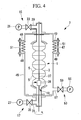
FIG. 4} FIG. 4 is a block diagram showing the schematic configuration of another welding device that implements a superconducting accelerating cavity production method according to an embodiment of the present invention. - An embodiment of a superconducting accelerating cavity production method of the present invention will be described below with reference to
FIGS. 1 to 3 .
FIG. 1 shows the schematic configuration of a welding device that implements a superconducting accelerating cavity production method according to an embodiment of the present invention.FIG. 2 is a partial sectional view, showing a step in the superconducting accelerating cavity production method according to this embodiment.FIG. 3 is a partial sectional view, showing another step in the superconducting accelerating cavity production method according to this embodiment. - As shown in
FIG. 1 , a superconducting acceleratingcavity 1 is a structure formed of, for example, fivecylindrical cells 3 bulging in the middle. In the superconducting acceleratingcavity 1, half-cells (ring-like members) 5 are formed by bending and press-molding, for example, a niobium material, which is a superconducting material, the half-cells 5 each constituting one of two segments of eachcell 3 bisectioned in the axial direction. The half-cell 5 extends between an equatorial portion 9 where thecell 3 bulges most, in the axial direction L, and aniris portion 11 where thecell 3 is recessed most. Each half-cell 5 is a ring-like member having openings at both ends, i.e., portions corresponding to the equatorial portion 9 and theiris portion 11. - The plurality of half-
cells 5 are arranged in the axial direction L such that the equatorial portions 9 overlap each other and such that theiris portions 11 overlap each other, and the contact portions are joined, thus forming the superconducting acceleratingcavity 1.
The ring-like member is not limited to the half-cell 5; thecell 3, the two half-cells 5 integrated at theiris portion 11, or other various configurations may be used. - As shown in
FIG. 1 , thewelding device 7 includes aholding member 13 for securing the superconducting acceleratingcavity 1 to prevent deformation thereof,vacuum suction members cavity 1, and alaser output device 19 disposed in the superconducting acceleratingcavity 1. - The
holding member 13 includes a pair ofholding plates 21 that securely hold both ends of the superconducting acceleratingcavity 1, and a plurality of securingshafts 23 that connect the pair ofholding plates 21 and maintain the distance therebetween. Thesecuring shafts 23 are made of a material whose coefficient of linear expansion is close to that of the material of the superconducting acceleratingcavity 1. For example, if the superconducting acceleratingcavity 1 is made of niobium, thesecuring shafts 23 are made of a niobium-zirconium alloy, titanium, or the like. - The
vacuum suction members vacuum pumps suction pipes vacuum pumps cavity 1, and on-offvalves suction pipes
Thesuction pipe 29 is connected to a flange portion at one end of the superconducting acceleratingcavity 1, and thesuction pipe 31 is connected to a flange portion at the other end. - The
laser output device 19 includes arotation shaft 37 attached to thesuction pipes cavity 1 and so as to be rotatable about the central axis, and alaser output portion 39 accommodating a laser optical system (not shown) for outputting a laser beam.
Therotation shaft 37 is rotated about the central axis by a driving device (not shown).
Thelaser output portion 39 is attached to therotation shaft 37 so as to be moveable in the axial direction L, while being prevented from moving in the rotation direction. Because thelaser output portion 39 is disposed in the vacuum atmosphere, a mirror of the laser optical system accommodated therein is cooled. The laser optical system receives light supplied from an external light source (not shown) through, for example, an optical fiber. - In the superconducting accelerating cavity production method according to this embodiment, first, a plurality of half-
cells 5 are stacked, and non-penetrationwelding 41 is performed on the equatorial portions 9 and theiris portions 11, which are joints, from the outer peripheral side, as shown inFIG. 2 . Thus, the inner space inside the superconducting acceleratingcavity 1 is sealed.
Thenon-penetration welding 41 on the outer peripheral side may be performed either by laser welding under an argon atmosphere, or by other known welding means. - In this state, the superconducting accelerating
cavity 1 is conveyed into thewelding device 7, and both ends thereof are securely attached to the holdingplates 21. The securingshafts 23 are attached to the holdingplates 21 so as to maintain the distance between the holdingplates 21.
Thesuction pipes cavity 1. At the same time, therotation shaft 37 and thelaser output portion 39 are attached so as to be positioned at predetermined positions in the inner space inside the superconducting acceleratingcavity 1. - In this state, the
vacuum pumps cavity 1, creating a pressure of about, for example, 1 × 10⁻⁴ Pa. As has been described, because the superconducting acceleratingcavity 1 itself can be used as the vacuum chamber, the need to prepare a separate vacuum chamber is eliminated. By doing so, it becomes possible to simplify the device configuration and perform joining with a compact device configuration, and the system can be constructed at low cost.
Furthermore, because a vacuum atmosphere for laser welding can be created by evacuating a limited area, i.e., the inner space inside the superconducting acceleratingcavity 1, a high vacuum can be easily realized.
Because the vacuum atmosphere can be created in a short time in this way, the working time can be reduced, and the labor costs can be reduced. - When a predetermined vacuum level of the inner space inside the superconducting accelerating
cavity 1 has been reached, a welding operation by thelaser output device 19 is started.
Thelaser output portion 39 is aligned with a joint. The laser optical system supplies light, i.e., a laser beam, supplied from the light source (not shown) to the joint of the half-cells 5 to perform non-penetration welding 43 on the equatorial portion 9 or theiris portion 11, which is the joint, from the inner peripheral side, as shown inFIG. 1 .
By rotating therotation shaft 37 at this time, thenon-penetration welding 43 can be performed on the entire inner peripheral surface of the superconducting acceleratingcavity 1. - Once welding is completed at one location, the
laser output portion 39 is moved along therotation shaft 37. Thelaser output portion 39 is moved to the next joint, and the laser welding is performed in the same manner.
When all the joints have been welded by repeating the above operation, the welding operation is completed.
Because a small-capacity vacuum atmosphere is created, i.e., only the inner space inside the superconducting acceleratingcavity 1, it is easy to create a high vacuum. Because welding can be performed in a high vacuum, a high-qualitysuperconducting accelerating cavity 1 can be produced. - Because the
vacuum pumps
By doing so, it is possible to prevent a foreign substance, such as gas, from depositing on the inner surface of the acceleratingcavity 1. Thus, a high-qualitysuperconducting accelerating cavity 1 can be produced. - In this embodiment, although the superconducting accelerating
cavity 1 is conveyed into thewelding device 7 after it has been integrated by being subjected to welding on the outer peripheral side, it may be welded by thewelding device 7.
For example, the stacked half-cells 5 may be held by the holdingmember 13 and welded from the outer peripheral side. - In this embodiment, after the superconducting accelerating
cavity 1 has been integrated by being subjected to welding on the outer peripheral side, a vacuum atmosphere is created in the superconducting acceleratingcavity 1, and welding on the inner peripheral side is performed. However, it is not limited thereto.
For example, as shown inFIG. 4 , instead of the holdingmember 13, avacuum chamber 45 having a space in which thesuperconducting accelerating cavity 1 can be accommodated may be provided.
Thevacuum chamber 45 has a cylindrical shape with the axis extending in the up-down direction, a portion thereof in the height direction constituting abellows portion 47 that can be expanded and contracted in the up-down direction. The lower end surface of thevacuum chamber 45 has a large opening into which thesuperconducting accelerating cavity 1 can be inserted. This opening is sealed by an end of thesuction pipe 31. - A plurality of pairs of
brackets 49, one above thebellows portion 47 and one below thebellows portion 47 and forming a pair, are provided at a certain interval in the peripheral direction. Securingshafts 51, each maintaining the distance between the pair of upper andlower brackets 49, are provided. The securingshafts 51 are attached in a removable manner.
Thebellows portion 47 expands and contracts in response to changes in height of the superconducting acceleratingcavity 1 in the up-down direction. When the superconducting acceleratingcavity 1 is installed, the securingshafts 51 are attached to limit the expansion and contraction of thebellows portion 47. - A
vacuum suction member 53 that evacuates the inside of thevacuum chamber 45 is provided. Thevacuum suction member 53 includes avacuum pump 55, asuction pipe 57 through which thevacuum pump 55 communicates with the inside of thevacuum chamber 45, and an on-offvalve 59 that opens/closes thesuction pipe 57. - The stacked half-
cells 5 are installed in thevacuum chamber 45. At this time, any variation in height of the superconducting acceleratingcavity 1 is absorbed by the expansion and contraction of thebellows portion 47.
Thesuction pipes cavity 1 and so as to seal thevacuum chamber 45.
At the same time, therotation shaft 37 and thelaser output portion 39 are attached so as to be positioned at predetermined positions in the inner space inside the acceleratingcavity 1.
When these tasks are completed, the securingshafts 51 are attached so that the distance between the pairs ofbrackets 49 does not change. - In this state, the vacuum pumps 25, 27, and 55 are activated to evacuate the inner spaces inside the superconducting accelerating
cavity 1 andvacuum chamber 45, creating a pressure of about 1 × 10⁻⁴ Pa, for example.
Because thevacuum chamber 45 is barely large enough to cover the circumference of the superconducting acceleratingcavity 1, the capacity to be evacuated is limited to a small area. By doing so, joining can be performed with a compact device configuration, and hence, the system can be constructed at low cost.
Furthermore, because the area in which a vacuum atmosphere is created is small, the vacuum atmosphere can be created in a short time. Because this enables a reduction in the working time, the labor costs can be reduced. In addition, because a high vacuum is easily realized, the welding can be performed in a high vacuum. Thus, a high-qualitysuperconducting accelerating cavity 1 can be produced. - When a predetermined vacuum level of the inner space inside the accelerating
cavity 1 has been reached, a welding operation by thelaser output device 19 is started. In this case, penetration welding is performed on the equatorial portions 9 and theiris portions 11, which are the joints, from the inner peripheral side.
By rotating therotation shaft 37 at this time, the penetration welding is performed on the entire inner peripheral surface of the superconducting acceleratingcavity 1.
Once welding is completed at one location, thelaser output portion 39 is moved to the next joint by following the above-described procedure, and the laser welding is performed in the same manner. - Because the
vacuum pumps
By doing so, a foreign substance, such as gas, can be prevented from depositing on the inner surface of the acceleratingcavity 1, and thus, a high-qualitysuperconducting accelerating cavity 1 can be produced. - Note that it is also possible that non-penetration welding is performed, from the inner peripheral side, on the superconducting accelerating
cavity 1, which has been integrated by being subjected to non-penetration welding from the outer peripheral side with the welding device shown inFIG. 4 .
By doing so, the difference in pressure between the inside and the outside of the superconducting acceleratingcavity 1 is reduced. Thus, the stress acting on the superconducting acceleratingcavity 1 can be eliminated. Accordingly, the risk of the superconducting acceleratingcavity 1 deforming can be eliminated. - Note that the present invention is not limited to the above-described embodiment, and it can be variously modified within a scope that does not depart from the spirit of the present invention.
-
- 1:
- superconducting accelerating cavity
- 3:
- cell
- 5:
- half-cell
Claims (3)
- A superconducting accelerating cavity production method in which a superconducting accelerating cavity is produced by arranging, in an axial direction, a plurality of ring-like members having openings at both ends in the axial direction and joining the openings to one another by welding,
wherein the ring-like members are joined by welding with a laser beam from the inside of the superconducting accelerating cavity, in which a vacuum atmosphere is created. - The superconducting accelerating cavity production method according to Claim 1,
wherein the inside of the superconducting accelerating cavity is evacuated to create a vacuum atmosphere. - The superconducting accelerating cavity production method according to Claim 1 or 2,
wherein non-penetration welding is performed from the outside prior to welding with the laser beam from the inside of the superconducting accelerating cavity.
Applications Claiming Priority (2)
| Application Number | Priority Date | Filing Date | Title |
|---|---|---|---|
| JP2009188354A JP5409186B2 (en) | 2009-08-17 | 2009-08-17 | Manufacturing method of superconducting acceleration cavity |
| PCT/JP2010/063628 WO2011021553A1 (en) | 2009-08-17 | 2010-08-11 | Manufacturing method for superconducting acceleration cavity |
Publications (3)
| Publication Number | Publication Date |
|---|---|
| EP2469989A1 true EP2469989A1 (en) | 2012-06-27 |
| EP2469989A4 EP2469989A4 (en) | 2014-12-17 |
| EP2469989B1 EP2469989B1 (en) | 2016-07-06 |
Family
ID=43607008
Family Applications (1)
| Application Number | Title | Priority Date | Filing Date |
|---|---|---|---|
| EP10809898.9A Not-in-force EP2469989B1 (en) | 2009-08-17 | 2010-08-11 | Manufacturing method for superconducting acceleration cavity |
Country Status (5)
| Country | Link |
|---|---|
| US (1) | US8883690B2 (en) |
| EP (1) | EP2469989B1 (en) |
| JP (1) | JP5409186B2 (en) |
| CA (1) | CA2766382C (en) |
| WO (1) | WO2011021553A1 (en) |
Families Citing this family (11)
| Publication number | Priority date | Publication date | Assignee | Title |
|---|---|---|---|---|
| JP5449019B2 (en) * | 2010-05-12 | 2014-03-19 | 三菱重工業株式会社 | Superconducting acceleration cavity and method of manufacturing superconducting acceleration cavity |
| JP5781278B2 (en) | 2010-05-14 | 2015-09-16 | 三菱重工業株式会社 | Welding equipment |
| US9756715B2 (en) * | 2013-12-11 | 2017-09-05 | Jefferson Science Associates, Llc | Flange joint system for SRF cavities utilizing high force spring clamps for low particle generation |
| GB2528863B (en) * | 2014-07-31 | 2016-07-13 | Elekta ltd | Radiotherapy systems and methods |
| JP5985011B1 (en) * | 2015-06-30 | 2016-09-06 | 三菱重工メカトロシステムズ株式会社 | Superconducting accelerator |
| DE102015212930B4 (en) | 2015-07-10 | 2019-05-23 | Heraeus Deutschland GmbH & Co. KG | Method for producing superconducting sealing rings |
| US11202362B1 (en) | 2018-02-15 | 2021-12-14 | Christopher Mark Rey | Superconducting resonant frequency cavities, related components, and fabrication methods thereof |
| US10856402B2 (en) * | 2018-05-18 | 2020-12-01 | Ii-Vi Delaware, Inc. | Superconducting resonating cavity with laser welded seam and method of formation thereof |
| JP2020187871A (en) * | 2019-05-10 | 2020-11-19 | 三菱重工機械システム株式会社 | Internal surface treatment method for superconducting accelerated cavities, manufacturing method for superconducting accelerated cavities, and surface treatment method for superconducting materials |
| CN114710872A (en) * | 2022-03-29 | 2022-07-05 | 中国科学院近代物理研究所 | A detachable nested composite superconducting cavity |
| JP2024021159A (en) * | 2022-08-03 | 2024-02-16 | 三菱重工機械システム株式会社 | acceleration cavity |
Family Cites Families (5)
| Publication number | Priority date | Publication date | Assignee | Title |
|---|---|---|---|---|
| JPH04218300A (en) * | 1990-10-31 | 1992-08-07 | Furukawa Electric Co Ltd:The | Superconductive acceleration tube and manufacture thereof |
| US5239157A (en) * | 1990-10-31 | 1993-08-24 | The Furukawa Electric Co., Ltd. | Superconducting accelerating tube and a method for manufacturing the same |
| JPH04322100A (en) * | 1991-04-19 | 1992-11-12 | Furukawa Electric Co Ltd:The | Manufacture of accelerating tube |
| JP3959198B2 (en) * | 1999-03-09 | 2007-08-15 | 株式会社東芝 | Superconducting cavity, manufacturing method thereof, and superconducting accelerator |
| JP4444222B2 (en) * | 2005-04-12 | 2010-03-31 | 三菱重工業株式会社 | Manufacturing method of superconducting acceleration cavity |
-
2009
- 2009-08-17 JP JP2009188354A patent/JP5409186B2/en active Active
-
2010
- 2010-08-11 EP EP10809898.9A patent/EP2469989B1/en not_active Not-in-force
- 2010-08-11 WO PCT/JP2010/063628 patent/WO2011021553A1/en not_active Ceased
- 2010-08-11 US US13/380,235 patent/US8883690B2/en not_active Expired - Fee Related
- 2010-08-11 CA CA2766382A patent/CA2766382C/en not_active Expired - Fee Related
Also Published As
| Publication number | Publication date |
|---|---|
| JP2011040321A (en) | 2011-02-24 |
| US20120100994A1 (en) | 2012-04-26 |
| CA2766382A1 (en) | 2011-02-24 |
| EP2469989A4 (en) | 2014-12-17 |
| EP2469989B1 (en) | 2016-07-06 |
| WO2011021553A1 (en) | 2011-02-24 |
| US8883690B2 (en) | 2014-11-11 |
| JP5409186B2 (en) | 2014-02-05 |
| CA2766382C (en) | 2015-07-07 |
Similar Documents
| Publication | Publication Date | Title |
|---|---|---|
| CA2766382C (en) | Superconducting accelerating cavity production method | |
| EP2571338B1 (en) | Superconducting acceleration cavity and method of manufacturing superconducting acceleration cavity | |
| US20240117787A1 (en) | Method for manufacturing tower tube section, tower tube section and wind turbine generator system | |
| JP4444222B2 (en) | Manufacturing method of superconducting acceleration cavity | |
| BR112014012912B1 (en) | End plate for isostatic hot pressing container, isostatic hot pressing container and method for isostatic hot pressing | |
| EP2571337B1 (en) | Method of producing superconducting accelerator cavity | |
| US6164945A (en) | Vacuum pump rotor and method of manufacturing the same | |
| US20230034648A1 (en) | Preactivated, batch fireable getter with integrated, miniature, single-actuation, extremely high-temperature bakeable valve | |
| WO2001086689A1 (en) | Photomultiplier tube and production method therefor | |
| US8957348B2 (en) | Welding equipment | |
| CN107584201A (en) | A kind of target vacuum diffusion bonding system and method | |
| JP4394985B2 (en) | Assemblies for the manufacture of hollow mechanical parts by diffusion bonding and superplastic forming, the use of such assemblies and processes for manufacturing such mechanical parts | |
| JPS6386230A (en) | X-ray image intensifier | |
| US20170047702A1 (en) | Vacuum container of laser oscillator | |
| JP3416615B2 (en) | Superconducting accelerator | |
| EP4715867A1 (en) | Method for repairing junction | |
| JP4600541B2 (en) | Short arc discharge lamp and manufacturing method thereof | |
| JPH02114428A (en) | Reproducible sealed electron tube device | |
| WO2019013250A1 (en) | Steam turbine system | |
| JP2020187871A (en) | Internal surface treatment method for superconducting accelerated cavities, manufacturing method for superconducting accelerated cavities, and surface treatment method for superconducting materials | |
| JP2001123804A (en) | Low-pressure casing of steam turbine | |
| WO2022070098A1 (en) | Field emission x-ray tube assembly and a method of making same | |
| JP4496803B2 (en) | Vacuum equipment | |
| JPH03236147A (en) | X-ray image multiplier and manufacture thereof | |
| JPH0845430A (en) | Vacuum sealer for electron tube |
Legal Events
| Date | Code | Title | Description |
|---|---|---|---|
| PUAI | Public reference made under article 153(3) epc to a published international application that has entered the european phase |
Free format text: ORIGINAL CODE: 0009012 |
|
| 17P | Request for examination filed |
Effective date: 20111221 |
|
| AK | Designated contracting states |
Kind code of ref document: A1 Designated state(s): AL AT BE BG CH CY CZ DE DK EE ES FI FR GB GR HR HU IE IS IT LI LT LU LV MC MK MT NL NO PL PT RO SE SI SK SM TR |
|
| DAX | Request for extension of the european patent (deleted) | ||
| A4 | Supplementary search report drawn up and despatched |
Effective date: 20141113 |
|
| RIC1 | Information provided on ipc code assigned before grant |
Ipc: H05H 7/20 20060101AFI20141107BHEP Ipc: B23K 26/00 20140101ALI20141107BHEP Ipc: B23K 26/12 20140101ALI20141107BHEP |
|
| 17Q | First examination report despatched |
Effective date: 20150908 |
|
| GRAP | Despatch of communication of intention to grant a patent |
Free format text: ORIGINAL CODE: EPIDOSNIGR1 |
|
| INTG | Intention to grant announced |
Effective date: 20160218 |
|
| RAP1 | Party data changed (applicant data changed or rights of an application transferred) |
Owner name: MITSUBISHI HEAVY INDUSTRIES MECHATRONICS SYSTEMS, |
|
| GRAS | Grant fee paid |
Free format text: ORIGINAL CODE: EPIDOSNIGR3 |
|
| GRAA | (expected) grant |
Free format text: ORIGINAL CODE: 0009210 |
|
| REG | Reference to a national code |
Ref country code: DE Ref legal event code: R084 Ref document number: 602010034551 Country of ref document: DE |
|
| AK | Designated contracting states |
Kind code of ref document: B1 Designated state(s): AL AT BE BG CH CY CZ DE DK EE ES FI FR GB GR HR HU IE IS IT LI LT LU LV MC MK MT NL NO PL PT RO SE SI SK SM TR |
|
| REG | Reference to a national code |
Ref country code: GB Ref legal event code: FG4D |
|
| REG | Reference to a national code |
Ref country code: AT Ref legal event code: REF Ref document number: 811495 Country of ref document: AT Kind code of ref document: T Effective date: 20160715 Ref country code: CH Ref legal event code: EP |
|
| REG | Reference to a national code |
Ref country code: IE Ref legal event code: FG4D |
|
| REG | Reference to a national code |
Ref country code: DE Ref legal event code: R096 Ref document number: 602010034551 Country of ref document: DE |
|
| REG | Reference to a national code |
Ref country code: FR Ref legal event code: PLFP Year of fee payment: 7 |
|
| REG | Reference to a national code |
Ref country code: NL Ref legal event code: MP Effective date: 20160706 |
|
| REG | Reference to a national code |
Ref country code: LT Ref legal event code: MG4D |
|
| REG | Reference to a national code |
Ref country code: AT Ref legal event code: MK05 Ref document number: 811495 Country of ref document: AT Kind code of ref document: T Effective date: 20160706 |
|
| PG25 | Lapsed in a contracting state [announced via postgrant information from national office to epo] |
Ref country code: BE Free format text: LAPSE BECAUSE OF NON-PAYMENT OF DUE FEES Effective date: 20160831 |
|
| PG25 | Lapsed in a contracting state [announced via postgrant information from national office to epo] |
Ref country code: HR Free format text: LAPSE BECAUSE OF FAILURE TO SUBMIT A TRANSLATION OF THE DESCRIPTION OR TO PAY THE FEE WITHIN THE PRESCRIBED TIME-LIMIT Effective date: 20160706 Ref country code: LT Free format text: LAPSE BECAUSE OF FAILURE TO SUBMIT A TRANSLATION OF THE DESCRIPTION OR TO PAY THE FEE WITHIN THE PRESCRIBED TIME-LIMIT Effective date: 20160706 Ref country code: IS Free format text: LAPSE BECAUSE OF FAILURE TO SUBMIT A TRANSLATION OF THE DESCRIPTION OR TO PAY THE FEE WITHIN THE PRESCRIBED TIME-LIMIT Effective date: 20161106 Ref country code: FI Free format text: LAPSE BECAUSE OF FAILURE TO SUBMIT A TRANSLATION OF THE DESCRIPTION OR TO PAY THE FEE WITHIN THE PRESCRIBED TIME-LIMIT Effective date: 20160706 Ref country code: NO Free format text: LAPSE BECAUSE OF FAILURE TO SUBMIT A TRANSLATION OF THE DESCRIPTION OR TO PAY THE FEE WITHIN THE PRESCRIBED TIME-LIMIT Effective date: 20161006 Ref country code: NL Free format text: LAPSE BECAUSE OF FAILURE TO SUBMIT A TRANSLATION OF THE DESCRIPTION OR TO PAY THE FEE WITHIN THE PRESCRIBED TIME-LIMIT Effective date: 20160706 |
|
| PG25 | Lapsed in a contracting state [announced via postgrant information from national office to epo] |
Ref country code: SE Free format text: LAPSE BECAUSE OF FAILURE TO SUBMIT A TRANSLATION OF THE DESCRIPTION OR TO PAY THE FEE WITHIN THE PRESCRIBED TIME-LIMIT Effective date: 20160706 Ref country code: ES Free format text: LAPSE BECAUSE OF FAILURE TO SUBMIT A TRANSLATION OF THE DESCRIPTION OR TO PAY THE FEE WITHIN THE PRESCRIBED TIME-LIMIT Effective date: 20160706 Ref country code: PT Free format text: LAPSE BECAUSE OF FAILURE TO SUBMIT A TRANSLATION OF THE DESCRIPTION OR TO PAY THE FEE WITHIN THE PRESCRIBED TIME-LIMIT Effective date: 20161107 Ref country code: GR Free format text: LAPSE BECAUSE OF FAILURE TO SUBMIT A TRANSLATION OF THE DESCRIPTION OR TO PAY THE FEE WITHIN THE PRESCRIBED TIME-LIMIT Effective date: 20161007 Ref country code: BE Free format text: LAPSE BECAUSE OF FAILURE TO SUBMIT A TRANSLATION OF THE DESCRIPTION OR TO PAY THE FEE WITHIN THE PRESCRIBED TIME-LIMIT Effective date: 20160706 Ref country code: PL Free format text: LAPSE BECAUSE OF FAILURE TO SUBMIT A TRANSLATION OF THE DESCRIPTION OR TO PAY THE FEE WITHIN THE PRESCRIBED TIME-LIMIT Effective date: 20160706 Ref country code: LV Free format text: LAPSE BECAUSE OF FAILURE TO SUBMIT A TRANSLATION OF THE DESCRIPTION OR TO PAY THE FEE WITHIN THE PRESCRIBED TIME-LIMIT Effective date: 20160706 Ref country code: AT Free format text: LAPSE BECAUSE OF FAILURE TO SUBMIT A TRANSLATION OF THE DESCRIPTION OR TO PAY THE FEE WITHIN THE PRESCRIBED TIME-LIMIT Effective date: 20160706 |
|
| REG | Reference to a national code |
Ref country code: CH Ref legal event code: PL |
|
| REG | Reference to a national code |
Ref country code: DE Ref legal event code: R097 Ref document number: 602010034551 Country of ref document: DE |
|
| PG25 | Lapsed in a contracting state [announced via postgrant information from national office to epo] |
Ref country code: RO Free format text: LAPSE BECAUSE OF FAILURE TO SUBMIT A TRANSLATION OF THE DESCRIPTION OR TO PAY THE FEE WITHIN THE PRESCRIBED TIME-LIMIT Effective date: 20160706 Ref country code: EE Free format text: LAPSE BECAUSE OF FAILURE TO SUBMIT A TRANSLATION OF THE DESCRIPTION OR TO PAY THE FEE WITHIN THE PRESCRIBED TIME-LIMIT Effective date: 20160706 Ref country code: LI Free format text: LAPSE BECAUSE OF NON-PAYMENT OF DUE FEES Effective date: 20160831 Ref country code: MC Free format text: LAPSE BECAUSE OF FAILURE TO SUBMIT A TRANSLATION OF THE DESCRIPTION OR TO PAY THE FEE WITHIN THE PRESCRIBED TIME-LIMIT Effective date: 20160706 Ref country code: CH Free format text: LAPSE BECAUSE OF NON-PAYMENT OF DUE FEES Effective date: 20160831 |
|
| PLBE | No opposition filed within time limit |
Free format text: ORIGINAL CODE: 0009261 |
|
| STAA | Information on the status of an ep patent application or granted ep patent |
Free format text: STATUS: NO OPPOSITION FILED WITHIN TIME LIMIT |
|
| PG25 | Lapsed in a contracting state [announced via postgrant information from national office to epo] |
Ref country code: SK Free format text: LAPSE BECAUSE OF FAILURE TO SUBMIT A TRANSLATION OF THE DESCRIPTION OR TO PAY THE FEE WITHIN THE PRESCRIBED TIME-LIMIT Effective date: 20160706 Ref country code: BG Free format text: LAPSE BECAUSE OF FAILURE TO SUBMIT A TRANSLATION OF THE DESCRIPTION OR TO PAY THE FEE WITHIN THE PRESCRIBED TIME-LIMIT Effective date: 20161006 Ref country code: CZ Free format text: LAPSE BECAUSE OF FAILURE TO SUBMIT A TRANSLATION OF THE DESCRIPTION OR TO PAY THE FEE WITHIN THE PRESCRIBED TIME-LIMIT Effective date: 20160706 Ref country code: SM Free format text: LAPSE BECAUSE OF FAILURE TO SUBMIT A TRANSLATION OF THE DESCRIPTION OR TO PAY THE FEE WITHIN THE PRESCRIBED TIME-LIMIT Effective date: 20160706 Ref country code: DK Free format text: LAPSE BECAUSE OF FAILURE TO SUBMIT A TRANSLATION OF THE DESCRIPTION OR TO PAY THE FEE WITHIN THE PRESCRIBED TIME-LIMIT Effective date: 20160706 |
|
| REG | Reference to a national code |
Ref country code: IE Ref legal event code: MM4A |
|
| 26N | No opposition filed |
Effective date: 20170407 |
|
| GBPC | Gb: european patent ceased through non-payment of renewal fee |
Effective date: 20161006 |
|
| REG | Reference to a national code |
Ref country code: FR Ref legal event code: PLFP Year of fee payment: 8 |
|
| PG25 | Lapsed in a contracting state [announced via postgrant information from national office to epo] |
Ref country code: IE Free format text: LAPSE BECAUSE OF NON-PAYMENT OF DUE FEES Effective date: 20160811 Ref country code: GB Free format text: LAPSE BECAUSE OF NON-PAYMENT OF DUE FEES Effective date: 20161006 |
|
| PG25 | Lapsed in a contracting state [announced via postgrant information from national office to epo] |
Ref country code: SI Free format text: LAPSE BECAUSE OF FAILURE TO SUBMIT A TRANSLATION OF THE DESCRIPTION OR TO PAY THE FEE WITHIN THE PRESCRIBED TIME-LIMIT Effective date: 20160706 Ref country code: LU Free format text: LAPSE BECAUSE OF NON-PAYMENT OF DUE FEES Effective date: 20160811 |
|
| PG25 | Lapsed in a contracting state [announced via postgrant information from national office to epo] |
Ref country code: HU Free format text: LAPSE BECAUSE OF FAILURE TO SUBMIT A TRANSLATION OF THE DESCRIPTION OR TO PAY THE FEE WITHIN THE PRESCRIBED TIME-LIMIT; INVALID AB INITIO Effective date: 20100811 Ref country code: CY Free format text: LAPSE BECAUSE OF FAILURE TO SUBMIT A TRANSLATION OF THE DESCRIPTION OR TO PAY THE FEE WITHIN THE PRESCRIBED TIME-LIMIT Effective date: 20160706 |
|
| PG25 | Lapsed in a contracting state [announced via postgrant information from national office to epo] |
Ref country code: TR Free format text: LAPSE BECAUSE OF FAILURE TO SUBMIT A TRANSLATION OF THE DESCRIPTION OR TO PAY THE FEE WITHIN THE PRESCRIBED TIME-LIMIT Effective date: 20160706 Ref country code: MK Free format text: LAPSE BECAUSE OF FAILURE TO SUBMIT A TRANSLATION OF THE DESCRIPTION OR TO PAY THE FEE WITHIN THE PRESCRIBED TIME-LIMIT Effective date: 20160706 Ref country code: MT Free format text: LAPSE BECAUSE OF NON-PAYMENT OF DUE FEES Effective date: 20160831 |
|
| REG | Reference to a national code |
Ref country code: FR Ref legal event code: PLFP Year of fee payment: 9 |
|
| REG | Reference to a national code |
Ref country code: FR Ref legal event code: CA Effective date: 20180821 Ref country code: FR Ref legal event code: CD Owner name: MITSUBISHI HEAVY INDUSTRIES MACHINERY SYSTEMS,, JP Effective date: 20180821 |
|
| PG25 | Lapsed in a contracting state [announced via postgrant information from national office to epo] |
Ref country code: AL Free format text: LAPSE BECAUSE OF FAILURE TO SUBMIT A TRANSLATION OF THE DESCRIPTION OR TO PAY THE FEE WITHIN THE PRESCRIBED TIME-LIMIT Effective date: 20160706 |
|
| REG | Reference to a national code |
Ref country code: DE Ref legal event code: R082 Ref document number: 602010034551 Country of ref document: DE Representative=s name: PATENTANWAELTE HENKEL, BREUER & PARTNER MBB, DE Ref country code: DE Ref legal event code: R081 Ref document number: 602010034551 Country of ref document: DE Owner name: MITSUBISHI HEAVY INDUSTRIES MACHINERY SYSTEMS,, JP Free format text: FORMER OWNER: MITSUBISHI HEAVY INDUSTRIES MECHATRONICS SYSTEMS, LTD., HYOGO-KU, KOBE, JP Ref country code: DE Ref legal event code: R082 Ref document number: 602010034551 Country of ref document: DE Representative=s name: HENKEL & PARTNER MBB PATENTANWALTSKANZLEI, REC, DE |
|
| PGFP | Annual fee paid to national office [announced via postgrant information from national office to epo] |
Ref country code: DE Payment date: 20190730 Year of fee payment: 10 Ref country code: IT Payment date: 20190821 Year of fee payment: 10 Ref country code: FR Payment date: 20190711 Year of fee payment: 10 |
|
| REG | Reference to a national code |
Ref country code: DE Ref legal event code: R119 Ref document number: 602010034551 Country of ref document: DE |
|
| PG25 | Lapsed in a contracting state [announced via postgrant information from national office to epo] |
Ref country code: DE Free format text: LAPSE BECAUSE OF NON-PAYMENT OF DUE FEES Effective date: 20210302 Ref country code: IT Free format text: LAPSE BECAUSE OF NON-PAYMENT OF DUE FEES Effective date: 20200811 Ref country code: FR Free format text: LAPSE BECAUSE OF NON-PAYMENT OF DUE FEES Effective date: 20200831 |