EP2469972B1 - Dispositif d'appareil de cuisson et procédé de contrôle d'un appareil de cuisson qui diminue d'une manière itérative une caractéristique flicker. - Google Patents
Dispositif d'appareil de cuisson et procédé de contrôle d'un appareil de cuisson qui diminue d'une manière itérative une caractéristique flicker. Download PDFInfo
- Publication number
- EP2469972B1 EP2469972B1 EP11194605.9A EP11194605A EP2469972B1 EP 2469972 B1 EP2469972 B1 EP 2469972B1 EP 11194605 A EP11194605 A EP 11194605A EP 2469972 B1 EP2469972 B1 EP 2469972B1
- Authority
- EP
- European Patent Office
- Prior art keywords
- control unit
- heating
- frequency
- unit
- cooking appliance
- Prior art date
- Legal status (The legal status is an assumption and is not a legal conclusion. Google has not performed a legal analysis and makes no representation as to the accuracy of the status listed.)
- Active
Links
- 238000010411 cooking Methods 0.000 title claims description 27
- 238000000034 method Methods 0.000 title claims description 12
- 230000003292 diminished effect Effects 0.000 claims 2
- 238000010438 heat treatment Methods 0.000 description 83
- 230000006698 induction Effects 0.000 description 23
- 230000001105 regulatory effect Effects 0.000 description 2
- 230000006978 adaptation Effects 0.000 description 1
- 230000002457 bidirectional effect Effects 0.000 description 1
- 230000033228 biological regulation Effects 0.000 description 1
- 239000003990 capacitor Substances 0.000 description 1
- 239000004020 conductor Substances 0.000 description 1
- 230000001276 controlling effect Effects 0.000 description 1
- 238000013016 damping Methods 0.000 description 1
- 230000003247 decreasing effect Effects 0.000 description 1
- 230000001419 dependent effect Effects 0.000 description 1
- 238000010586 diagram Methods 0.000 description 1
- 239000002241 glass-ceramic Substances 0.000 description 1
- 230000000737 periodic effect Effects 0.000 description 1
- 230000002441 reversible effect Effects 0.000 description 1
- 230000003595 spectral effect Effects 0.000 description 1
- 230000007704 transition Effects 0.000 description 1
- 230000016776 visual perception Effects 0.000 description 1
Images

Classifications
-
- H—ELECTRICITY
- H05—ELECTRIC TECHNIQUES NOT OTHERWISE PROVIDED FOR
- H05B—ELECTRIC HEATING; ELECTRIC LIGHT SOURCES NOT OTHERWISE PROVIDED FOR; CIRCUIT ARRANGEMENTS FOR ELECTRIC LIGHT SOURCES, IN GENERAL
- H05B6/00—Heating by electric, magnetic or electromagnetic fields
- H05B6/02—Induction heating
- H05B6/06—Control, e.g. of temperature, of power
- H05B6/062—Control, e.g. of temperature, of power for cooking plates or the like
- H05B6/065—Control, e.g. of temperature, of power for cooking plates or the like using coordinated control of multiple induction coils
Definitions
- the invention is based on a cooking device device according to the preamble of claim 1.
- the publication EP 1 951 003 B1 discloses an induction hob with at least two heating frequency units operated according to a particular method to prevent intermodulation noises. According to this method, both heating-frequency units are operated at an identical first frequency in a first time period. In a second period of time, one heating frequency unit is switched off, while the other heating frequency unit is operated at a second frequency. The two frequencies as well as the relative lengths of the two time segments are adjusted so that a mean output power of each heating frequency unit corresponds to an operator selected heating power.
- the object of the invention is in particular to provide a generic Garellavorraum, which is network compliant in any operating condition.
- the object is achieved by the features of claim 1 and the method claim 9, while advantageous embodiments and refinements of the invention can be taken from the dependent claims.
- the invention is based on a cooking device device with at least two heating frequency units and with at least one control unit, which is provided to set a respective average output power of the heating frequency units.
- the control unit is provided to iteratively reduce a patch parameter.
- the cooking device device is preferably a hob device and particularly advantageous as an induction hob device educated.
- provided is intended to be understood in particular specially programmed and / or designed and / or equipped.
- a “heating frequency unit” should in particular be understood to mean an electrical unit which generates an oscillating electrical current, preferably with a frequency of at least 1 kHz, in particular of at least 10 kHz and advantageously of at least 20 kHz, for operation of at least one heating unit.
- a “heating unit” is to be understood in particular a unit which is intended to at least partially convert electrical energy into heat and thus in particular to heat a food to be cooked.
- the heating unit comprises a radiant heater, a resistance heater and / or preferably an induction heater, which is intended to convert electrical energy indirectly via induced eddy currents into heat.
- the heating frequency unit comprises in particular at least one inverter, which preferably comprises two switching units.
- a "switching unit” is to be understood in particular a unit which is intended to interrupt a parts of the switching unit comprehensive line path.
- the switching unit is a bidirectional unipolar switch which in particular allows a current flow through the switch along the conduction path in both directions and in particular short-circuits an electrical voltage in at least one polarity direction.
- the inverter comprises at least two bipolar transistors with insulated gate electrode and particularly advantageously at least one damping capacitor.
- a "conduction path” is to be understood as meaning, in particular, an electrically conductive conductor piece between two points.
- control unit is to be understood, in particular, as an electronic unit which is preferably at least partially integrated in a control and / or regulating unit of a cooking appliance, in particular an induction hob.
- the control unit comprises a computing unit and in particular in addition to the computing unit, a memory unit with a control program stored therein.
- the control unit is provided to control the heating frequency units by means of electrical control signals and / or to regulate.
- An electrical "control signal” is to be understood in particular a signal having an electrical voltage of at most 30 V, preferably of at most 20 V and more preferably of at most 10 V, which is supplied in particular in at least one operating state, the inverters of the heating frequency units.
- the control signal has a periodicity at least at times, in particular with a period of at most 1 ms, in particular of at most 0.1 ms and advantageously of at most 0.05 ms.
- the control signal is a square-wave signal, which in particular can assume two values, preferably a switch-on value and a switch-off value.
- each of the two values corresponds to a switching position of the inverters.
- a "frequency" of a heating frequency unit is to be understood in particular as the frequency of the control signal controlling the heating frequency unit.
- An “output power” is to be understood, in particular, as meaning an electrical power which, in at least one operating state, is transmitted from a heating frequency unit to a heating unit.
- the output power is transmitted by an electric current.
- the output power is preferably converted in the heating unit at least partially and particularly advantageously at least to a large extent into a heat flow.
- a “mean output power” is to be understood in particular a time-averaged output power.
- the control unit is provided to set the average output power such that a selected by an operator heating power is achieved, in particular for each heating zone of a hob.
- a “Flickerkennhim” should be understood as a parameter that represents a measure of flicker.
- flicker is meant in particular a subjective impression of instability of a visual perception, which is caused in particular by a light stimulus whose luminance or spectral distribution varies with time.
- flicker can be caused by a voltage drop of a mains voltage.
- the flicker characteristic is preferably an overall output power difference, preferably between two times of two time ranges and particularly advantageous two adjacent time ranges.
- a “total output power” is to be understood as meaning, in particular, a sum of the output powers of all heating-frequency units at a particular point in time.
- total output power difference is to be understood in particular as a difference of the total output powers at two different points in time.
- control unit is intended to "iteratively reduce” a patch parameter
- control unit is intended to execute a loop-shaped algorithm, the patch characteristic preferably being smaller in each loop of the algorithm than in a previous one Loop.
- control unit is provided to reduce a total output power difference between times of two, preferably adjacent, time periods.
- Such a configuration can ensure that the cooking appliance device operates in line with the network in each operating state. Furthermore, the flicker characteristic can always be controlled and, in particular, lowered below a statutory and / or normative limit. Furthermore, a control unit can be provided with an advantageously simple control algorithm.
- control unit is provided to lower the flicker characteristic below a threshold.
- the limit value is preferably a value defined by at least one statutory requirement and / or standard, in particular the standard DIN EN 61000-3-3. This will ensure compliance with legal and / or regulatory limits. In particular, a perceptible by a human swaying a light intensity due to voltage fluctuations in a mains voltage can be avoided thereby.
- the control unit is provided for a time interval in at least two subintervals split taking into account at least one output power.
- the control unit is provided to operate at least one of the heating frequency units in the sub-intervals, each with a different output power.
- the control unit is provided to operate the heating frequency units in each case in a sub-interval with constant operating parameters, in particular a constant frequency and / or a constant duty cycle.
- a ratio of a time duration in which the control signal assumes the switch-on value within a period duration to the period duration of the control signal is to be understood as a "duty cycle".
- intermodulation noise should be understood in particular that intermodulation noises at a frequency of 17 kHz and smaller at a distance of 1 m from the cooking appliance a sound pressure level of at most 20 dB, in particular of at most 10 dB, preferably of at most 5 dB and particularly advantageous of a maximum of 0 dB.
- the intermodulation sounds are inaudible to an average hearing operator.
- control unit is provided to reduce the patch parameter between the two sub-intervals.
- control unit is intended to "reduce the flicker characteristic between the two subintervals”
- the control unit is intended to be identical with the flicker characteristic calculated from operating parameters of the two subintervals, which is identical in particular to the total output power difference of the two subintervals is to downsize and preferably iteratively to downsize.
- control unit is provided to gradually reduce a frequency of at least one of the heating frequency units.
- a Reduction in equidistant steps Preferably, a step size of 30 Hz to 90 Hz, preferably 50 Hz to 70 Hz and particularly advantageously about 60 Hz. This can be a reliable algorithm can be created, which comes within a short time advantageous to a result.
- control unit is intended to use as start value a frequency between 60 kHz and 90 kHz.
- control unit is intended to use as start value a frequency between 70 kHz and 80 kHz, and particularly advantageously about 75 kHz.
- start value should be understood in particular to be a numerical value for the loop-shaped algorithm which is used in a first loop of the algorithm and which is changed by the algorithm in subsequent loops of the algorithm. As a result, an average runtime of the algorithm can be advantageously reduced.
- the control unit is provided to adapt a duty cycle.
- the output power can be changed.
- the control unit is intended to adapt a duty cycle
- the control unit is intended to change the duty cycle of at least one of the heating frequency units, thereby changing the output power at a fixed frequency in at least one operating state to reach the heating frequency unit.
- the control unit is provided to keep temporally as constant as possible by varying the duty cycle of at least one of the two Schufrequenzüen a total output power of both Schufrequenzüen in at least one operating state. As a result, a more continuous output of the heating frequency units can be made possible. Furthermore, flexibility of the algorithm can be increased.
- control unit is provided to use as start value a duty cycle between 0.4 and 0.6.
- control unit is provided to use as the starting value a duty cycle between 0.45 and 0.55 and particularly advantageously about 0.5.
- an average runtime of the algorithm can be advantageously reduced.
- a method is proposed with a cooking device device with at least two heating frequency units, in which a respective average output power of the heating frequency units is set, wherein a flicker characteristic is iteratively reduced.
- the flicker characteristic can always be controlled and lowered in particular under a statutory and / or prescribed by standards limit.
- a cooking appliance in particular a hob, proposed with a Garellavorraum invention.
- the hob is an induction hob.
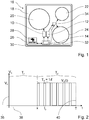
- Fig. 1 shows a trained as induction hob 16 cooking appliance.
- the induction hob 16 comprises a hob plate 18, in particular of a glass ceramic, on which in a known manner three heating zones 20, 22, 24 are marked.
- the hob plate 18 is arranged horizontally in an operational state of the induction hob 16 and provided for setting up cooking utensils. Furthermore, touch-sensitive operating elements 26 and display elements 28 of an operating and display unit 30 of the induction hob 16 are marked on the hob plate 18 in a known manner.
- the induction hob 16 further comprises a cooking device device with two heating frequency units 10, 12 arranged below the hob plate 18 and with a control unit 14 arranged below the hob plate 18 Fig.
- the control unit 14 is integrated in a control and regulation unit 32 of the induction hob 16.
- One of the heating zone 20 associated and disposed below this induction heating unit is powered by the heating frequency unit 10 with energy.
- One of the heating zone 22 associated and arranged below this induction heating unit and another of the heating zone 24 associated and arranged below this induction heating unit are supplied via a switching unit 34 of the cooking appliance by the heating frequency unit 12 with energy.
- the switching unit 34 is provided for operating the two induction heating units assigned to the two heating zones 22, 24 in a known manner in a time division multiplex controlled by the control unit 14.
- the control unit 14 is provided to set a respective average output power P 0A , P 0B of the heating frequency units 10, 12, so that the selected Schuzprocessn the heating zones 20, 22, 24 are achieved, in particular using the time division multiplex, while Intermodulationsgehoffsche be avoided.
- the control unit 14 controls the heating frequency unit 10 by means of a control signal V A (t) and the heating frequency unit 12 by means of a control signal V B (t).
- Fig. 2 shows by way of example a non-to-scale control signal V A (t) in a Cartesian coordinate system.
- a control voltage V A and on a abscissa axis 38 a time t is plotted.
- the control signal V A (t) during a sub-interval T 2 of a time interval T is a rectangular signal with a switch-on value V 0 and a switch-off value of 0 volts.
- the switch-on value V 0 is held during a switch-on time t 0 .
- a period of the rectangular signal is T 0 .
- the turn-off value is held.
- a frequency f of the control signal V A (t) is calculated from a reciprocal of the period T 0 .
- the frequency f is usually between 30 kHz and 100 kHz.
- a duty cycle D A of the control signal V A (t) is calculated from a quotient of the switch-on time t 0 divided by the period T 0 .
- An envelope 40 of the control signal V A (t) is shown in dashed lines. While V A (t) takes the form of the rectangular signal, an inverter of the heating frequency unit 10 is periodically switched in accordance with a periodic change of the ON value V 0 and the OFF value. This results in a high-frequency alternating current to an operation of the heating zone 20 associated induction heating unit.
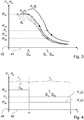
- P A (f) a power frequency curve
- On an ordinate axis 42 are output powers P A and P B of the heating frequency units 10, 12 applied.
- abscissa axis 44 the frequency f is plotted.
- the heating frequency unit 12 which requires a lower frequency f to achieve the average output power P 0B in a continuous operation, is operated in the two subintervals T 1 and T 2 of the time interval T with fixed frequencies f 1 and f 2 and with duty cycles D B1 and D B2 operated.
- the heating frequency unit 10 is operated at the frequency f 2 in the partial interval T 2 , in which the heating frequency unit 12 is operated at the higher frequency f 2 > f 1 .
- Fig. 4 shows in a Cartesian coordinate system by way of example two power-time curves P A (t) and P B (t).
- the output powers P A and P B of the heating frequency units 10, 12 are plotted on an ordinate axis 46.
- the time t is plotted on an abscissa axis 48.
- Fig. 4 shows how the heating frequency unit 12 in the first sub-interval T 1 with the frequency f 1 and the duty cycle D B1 is operated while the heating frequency unit 10 is turned off.
- both heating-frequency units 10, 12 are operated with the same frequency f 2 > f 1 and with duty cycles D A and D B2 .
- intermodulation hum can be effectively avoided.
- the output power P A during the sub-interval T 2 is greater than the average output power P 0A .
- an output power P B1 for the heating frequency unit 12 in the first sub-interval T 1 is greater than the average output power P 0B .
- an output power P B2 is smaller than the average output power P 0B .
- a determination of the sub-intervals T 1 and T 2 , the frequencies f 1 and f 2 and the duty D A and D B2 is carried out under iterative minimization of a flicker F under a set by the standard DIN EN 61000-3-3 limit F G.
- the control unit 14 is intended to be a in Fig. 5 to perform a flowchart illustrated method for minimizing the patch characteristic F. The method starts with a step 58 after a selection of heating powers for the heating zones 20, 22, 24 by an operator.
- the average output power P 0A and P 0B is determined for the heating frequency units 10, 12.
- a starting value of 75 kHz is selected.
- a starting value of 0.5 is selected for the duty cycles D A , D B1 and D B2 .
- a step 64 the output powers P B1 and P B2 are determined during the sub-intervals T 1 and T 2 for the heating frequency unit 12, so that the mean Output power P 0B results. From the output power P B1 , the frequency f 1 is determined. In a step 66, the patch characteristic F is calculated. In a branch 68 it is checked whether the flicker characteristic F is greater than the limit value F G. If this is not the case, then the method ends with a step 70. The method has then as a result of the time x, the frequencies f 1 and f 2 and the duty cycles D A , D B1 and D B2 for the heating frequency units 10, 12 determined , so that the flicker characteristic F corresponds to the standard.
- a step 72 the duty cycle D B2 is decreased by a value of 0.05.
- a branch 74 it is checked whether the duty cycle D B2 is equal to zero. If the duty cycle D B2 is not equal to zero, there is a jump to step 64, in which a redetermination of the output powers P B1 and P B2 occurs. If the duty cycle D B2 is equal to zero, the duty cycle D B2 is reset to 0.5 in a step 76. Instead, will the duty cycle D A is lowered by a value of 0.05. In a branch 78 it is checked whether the duty cycle D A is equal to zero.
- step 62 If the duty cycle D A is not equal to zero, there is a jump to step 62, in which a redetermination of the time x takes place. If the duty cycle D A is equal to zero, the frequency f 2 is reduced by a value of 60 Hz in a step 80. In addition, a jump is made to step 60 in which the duty cycles D A and D B2 are reset to 0.5 become.
- adaptation of the duty cycles D A and D B2 can also be dispensed with. It is also conceivable that only one of the duty cycles D A or D B2 is adjusted.
- an induction hob can also have four induction heating units, wherein two of the induction heating units are each connected via a switching unit to a heating frequency unit.
- two induction heating units assigned to a heating frequency unit can also be operated by any other method that appears appropriate to a person skilled in the art.
- more than two induction heating units are assigned to a heating frequency unit.
Landscapes
- Physics & Mathematics (AREA)
- Electromagnetism (AREA)
- Electric Stoves And Ranges (AREA)
Claims (10)
- Dispositif d'appareil de cuisson doté d'au moins deux unités de fréquence de chauffage (10, 12) et d'au moins une unité de commande (14) prévue pour établir une puissance de sortie moyenne respective (P0A, P0B) des unités de fréquence de chauffage (10, 12), l'unité de commande (14) étant prévue pour diminuer une caractéristique flicker (F) qui est une mesure du papillotement, caractérisé en ce que l'unité de commande (14) est prévue pour diminuer la caractéristique flicker (F) de manière itérative.
- Dispositif d'appareil de cuisson selon la revendication 1, caractérisé en ce que l'unité de commande (14) est prévue pour abaisser la caractéristique flicker (F) en dessous d'une valeur limite (FG).
- Dispositif d'appareil de cuisson selon la revendication 1 ou 2, caractérisé en ce que l'unité de commande (14) est prévue pour diviser un intervalle de temps (T) en au moins deux intervalles partiels (T1, T2) en tenant compte d'au moins une puissance de sortie (PA).
- Dispositif d'appareil de cuisson selon la revendication 3, caractérisé en ce que l'unité de commande (14) est prévue pour diminuer la caractéristique flicker (F) entre les deux intervalles partiels (T1, T2).
- Dispositif d'appareil de cuisson selon l'une des revendications précédentes, caractérisé en ce que l'unité de commande (14) est prévue pour diminuer de manière progressive une fréquence (f2) d'au moins l'une des unités de fréquence de chauffage (10, 12).
- Dispositif d'appareil de cuisson selon la revendication 5, caractérisé en ce que l'unité de commande (14) est prévue pour utiliser comme valeur de départ une fréquence (f2) comprise entre 60 kHz et 90 kHz.
- Dispositif d'appareil de cuisson selon l'une des revendications précédentes, caractérisé en ce que l'unité de commande (14) est prévue pour adapter un rapport cyclique (DA, DB2).
- Dispositif d'appareil de cuisson selon la revendication 7, caractérisé en ce que l'unité de commande (14) est prévue pour utiliser comme valeur de départ un rapport cyclique (DA, DB2) compris entre 0,4 et 0,6.
- Procédé comprenant un dispositif d'appareil de cuisson doté d'au moins deux unités de fréquence de chauffage (10, 12), en particulier selon l'une des revendications précédentes, dans lequel une puissance de sortie moyenne respective (P0A, P0B) des unités de fréquence de chauffage (10, 12) est établie, et une caractéristique flicker (F), qui est une mesure du papillotement, est diminuée, caractérisé en ce que la caractéristique flicker (F) est diminuée de manière itérative.
- Appareil de cuisson, en particulier table de cuisson, comprenant un dispositif d'appareil de cuisson selon l'une des revendications 1 à 8.
Applications Claiming Priority (1)
| Application Number | Priority Date | Filing Date | Title |
|---|---|---|---|
| ES201031948 | 2010-12-27 |
Publications (2)
| Publication Number | Publication Date |
|---|---|
| EP2469972A1 EP2469972A1 (fr) | 2012-06-27 |
| EP2469972B1 true EP2469972B1 (fr) | 2017-05-03 |
Family
ID=45470300
Family Applications (1)
| Application Number | Title | Priority Date | Filing Date |
|---|---|---|---|
| EP11194605.9A Active EP2469972B1 (fr) | 2010-12-27 | 2011-12-20 | Dispositif d'appareil de cuisson et procédé de contrôle d'un appareil de cuisson qui diminue d'une manière itérative une caractéristique flicker. |
Country Status (1)
| Country | Link |
|---|---|
| EP (1) | EP2469972B1 (fr) |
Families Citing this family (4)
| Publication number | Priority date | Publication date | Assignee | Title |
|---|---|---|---|---|
| ES2564888B1 (es) * | 2014-09-24 | 2017-01-05 | BSH Electrodomésticos España S.A. | Dispositivo de aparato de cocción y procedimiento para la puesta en funcionamiento de un dispositivo de aparato de cocción |
| EP3432682A1 (fr) * | 2017-07-18 | 2019-01-23 | Whirlpool Corporation | Procédé de fonctionnement d'une plaque de cuisson par induction et plaque de cuisson faisant appel à un tel procédé |
| KR102620662B1 (ko) * | 2018-10-18 | 2024-01-04 | 삼성전자주식회사 | 조리 기기 및 이의 제어 방법 |
| US11910509B2 (en) | 2021-03-02 | 2024-02-20 | Whirlpool Corporation | Method for improving accuracy in load curves acquisition on an induction cooktop |
Family Cites Families (3)
| Publication number | Priority date | Publication date | Assignee | Title |
|---|---|---|---|---|
| ES2201937B1 (es) * | 2003-11-03 | 2005-02-01 | Bsh Electrodomesticos España, S.A. | Procedimiento para el funcionamiento de un circuito convertidor. |
| ES2338057T5 (es) * | 2007-01-23 | 2023-03-09 | Whirlpool Co | Método de control para una placa de cocina de inducción y placa de cocina de inducción adaptada para llevar a cabo dicho método |
| ES2370296T3 (es) * | 2008-12-22 | 2011-12-14 | Fagorbrandt Sas | Procedimiento de alimentación de potencia de dos inductores y aparato de cocción que aplica dicho procedimiento. |
-
2011
- 2011-12-20 EP EP11194605.9A patent/EP2469972B1/fr active Active
Also Published As
| Publication number | Publication date |
|---|---|
| EP2469972A1 (fr) | 2012-06-27 |
Similar Documents
| Publication | Publication Date | Title |
|---|---|---|
| EP1935213B1 (fr) | Procede pour faire fonctionner un systeme de chauffage par induction | |
| EP2469970B1 (fr) | Dispositif d'appareil de cuisson | |
| DE602005003310T2 (de) | Umrichterschaltung für Induktionsheizvorrichtung, Kochgerät mit einer solchen Schaltung und Betriebsverfahren | |
| EP2506663B1 (fr) | Dispositif d'appareil de cuisson | |
| EP2506665B1 (fr) | Dispositif d'appareil de cuisson | |
| EP2469972B1 (fr) | Dispositif d'appareil de cuisson et procédé de contrôle d'un appareil de cuisson qui diminue d'une manière itérative une caractéristique flicker. | |
| EP3560276A1 (fr) | Dispositif formant appareil de cuisson et procédé de fonctionnement d'un dispositif formant appareil de cuisson | |
| EP2506666B1 (fr) | Dispositif d'appareil de cuisson | |
| DE19708335B4 (de) | Heizleistungsregulierung für Induktionskochherd | |
| EP2469971B1 (fr) | Dispositif d'appareil de cuisson | |
| EP2506673B1 (fr) | Plaque de cuisson a induction | |
| EP2692202B1 (fr) | Dispositif de chauffage par induction | |
| EP2911472A2 (fr) | Dispositif d'appareil de cuisson, en particulier dispositif de plaque de cuisson, doté d'une pluralité d'onduleurs | |
| WO2020229336A1 (fr) | Ensemble appareil de cuisson | |
| EP3641497B1 (fr) | Dispositif formant appareil de cuisson | |
| EP2506664B1 (fr) | Dispositif d'appareil de cuisson | |
| WO2018178786A1 (fr) | Dispositif pour appareil ménager et procédé pour faire fonctionner un dispositif pour appareil ménager | |
| EP1494505B1 (fr) | Méthode et dispositif de régulation de puissance pour plaques à inductions | |
| EP3641494B1 (fr) | Dispositif formant appareil de cuisson | |
| EP2548407B1 (fr) | Dispositif de table de cuisson | |
| EP3662724B1 (fr) | Appareil de commande pour une charge électrique et procédé | |
| EP2945461B1 (fr) | Dispositif d'appareil de cuisson | |
| DE102017220963A1 (de) | Gargerätevorrichtung | |
| DE102012211399A1 (de) | Hausgerätevorrichtung | |
| EP3664578A1 (fr) | Dispositif formant appareil de cuisson |
Legal Events
| Date | Code | Title | Description |
|---|---|---|---|
| AK | Designated contracting states |
Kind code of ref document: A1 Designated state(s): AL AT BE BG CH CY CZ DE DK EE ES FI FR GB GR HR HU IE IS IT LI LT LU LV MC MK MT NL NO PL PT RO RS SE SI SK SM TR |
|
| AX | Request for extension of the european patent |
Extension state: BA ME |
|
| PUAI | Public reference made under article 153(3) epc to a published international application that has entered the european phase |
Free format text: ORIGINAL CODE: 0009012 |
|
| 17P | Request for examination filed |
Effective date: 20130102 |
|
| RAP1 | Party data changed (applicant data changed or rights of an application transferred) |
Owner name: BSH HAUSGERAETE GMBH |
|
| GRAP | Despatch of communication of intention to grant a patent |
Free format text: ORIGINAL CODE: EPIDOSNIGR1 |
|
| INTG | Intention to grant announced |
Effective date: 20161201 |
|
| GRAS | Grant fee paid |
Free format text: ORIGINAL CODE: EPIDOSNIGR3 |
|
| GRAA | (expected) grant |
Free format text: ORIGINAL CODE: 0009210 |
|
| AK | Designated contracting states |
Kind code of ref document: B1 Designated state(s): AL AT BE BG CH CY CZ DE DK EE ES FI FR GB GR HR HU IE IS IT LI LT LU LV MC MK MT NL NO PL PT RO RS SE SI SK SM TR |
|
| REG | Reference to a national code |
Ref country code: GB Ref legal event code: FG4D Free format text: NOT ENGLISH |
|
| REG | Reference to a national code |
Ref country code: AT Ref legal event code: REF Ref document number: 891283 Country of ref document: AT Kind code of ref document: T Effective date: 20170515 Ref country code: CH Ref legal event code: EP |
|
| REG | Reference to a national code |
Ref country code: IE Ref legal event code: FG4D Free format text: LANGUAGE OF EP DOCUMENT: GERMAN |
|
| REG | Reference to a national code |
Ref country code: DE Ref legal event code: R096 Ref document number: 502011012154 Country of ref document: DE |
|
| REG | Reference to a national code |
Ref country code: NL Ref legal event code: MP Effective date: 20170503 |
|
| REG | Reference to a national code |
Ref country code: LT Ref legal event code: MG4D |
|
| PG25 | Lapsed in a contracting state [announced via postgrant information from national office to epo] |
Ref country code: HR Free format text: LAPSE BECAUSE OF FAILURE TO SUBMIT A TRANSLATION OF THE DESCRIPTION OR TO PAY THE FEE WITHIN THE PRESCRIBED TIME-LIMIT Effective date: 20170503 Ref country code: LT Free format text: LAPSE BECAUSE OF FAILURE TO SUBMIT A TRANSLATION OF THE DESCRIPTION OR TO PAY THE FEE WITHIN THE PRESCRIBED TIME-LIMIT Effective date: 20170503 Ref country code: FI Free format text: LAPSE BECAUSE OF FAILURE TO SUBMIT A TRANSLATION OF THE DESCRIPTION OR TO PAY THE FEE WITHIN THE PRESCRIBED TIME-LIMIT Effective date: 20170503 Ref country code: NO Free format text: LAPSE BECAUSE OF FAILURE TO SUBMIT A TRANSLATION OF THE DESCRIPTION OR TO PAY THE FEE WITHIN THE PRESCRIBED TIME-LIMIT Effective date: 20170803 Ref country code: ES Free format text: LAPSE BECAUSE OF FAILURE TO SUBMIT A TRANSLATION OF THE DESCRIPTION OR TO PAY THE FEE WITHIN THE PRESCRIBED TIME-LIMIT Effective date: 20170503 |
|
| PG25 | Lapsed in a contracting state [announced via postgrant information from national office to epo] |
Ref country code: NL Free format text: LAPSE BECAUSE OF FAILURE TO SUBMIT A TRANSLATION OF THE DESCRIPTION OR TO PAY THE FEE WITHIN THE PRESCRIBED TIME-LIMIT Effective date: 20170503 Ref country code: SE Free format text: LAPSE BECAUSE OF FAILURE TO SUBMIT A TRANSLATION OF THE DESCRIPTION OR TO PAY THE FEE WITHIN THE PRESCRIBED TIME-LIMIT Effective date: 20170503 Ref country code: PL Free format text: LAPSE BECAUSE OF FAILURE TO SUBMIT A TRANSLATION OF THE DESCRIPTION OR TO PAY THE FEE WITHIN THE PRESCRIBED TIME-LIMIT Effective date: 20170503 Ref country code: IS Free format text: LAPSE BECAUSE OF FAILURE TO SUBMIT A TRANSLATION OF THE DESCRIPTION OR TO PAY THE FEE WITHIN THE PRESCRIBED TIME-LIMIT Effective date: 20170903 Ref country code: RS Free format text: LAPSE BECAUSE OF FAILURE TO SUBMIT A TRANSLATION OF THE DESCRIPTION OR TO PAY THE FEE WITHIN THE PRESCRIBED TIME-LIMIT Effective date: 20170503 Ref country code: LV Free format text: LAPSE BECAUSE OF FAILURE TO SUBMIT A TRANSLATION OF THE DESCRIPTION OR TO PAY THE FEE WITHIN THE PRESCRIBED TIME-LIMIT Effective date: 20170503 Ref country code: BG Free format text: LAPSE BECAUSE OF FAILURE TO SUBMIT A TRANSLATION OF THE DESCRIPTION OR TO PAY THE FEE WITHIN THE PRESCRIBED TIME-LIMIT Effective date: 20170803 |
|
| PG25 | Lapsed in a contracting state [announced via postgrant information from national office to epo] |
Ref country code: SK Free format text: LAPSE BECAUSE OF FAILURE TO SUBMIT A TRANSLATION OF THE DESCRIPTION OR TO PAY THE FEE WITHIN THE PRESCRIBED TIME-LIMIT Effective date: 20170503 Ref country code: DK Free format text: LAPSE BECAUSE OF FAILURE TO SUBMIT A TRANSLATION OF THE DESCRIPTION OR TO PAY THE FEE WITHIN THE PRESCRIBED TIME-LIMIT Effective date: 20170503 Ref country code: CZ Free format text: LAPSE BECAUSE OF FAILURE TO SUBMIT A TRANSLATION OF THE DESCRIPTION OR TO PAY THE FEE WITHIN THE PRESCRIBED TIME-LIMIT Effective date: 20170503 Ref country code: EE Free format text: LAPSE BECAUSE OF FAILURE TO SUBMIT A TRANSLATION OF THE DESCRIPTION OR TO PAY THE FEE WITHIN THE PRESCRIBED TIME-LIMIT Effective date: 20170503 Ref country code: RO Free format text: LAPSE BECAUSE OF FAILURE TO SUBMIT A TRANSLATION OF THE DESCRIPTION OR TO PAY THE FEE WITHIN THE PRESCRIBED TIME-LIMIT Effective date: 20170503 |
|
| REG | Reference to a national code |
Ref country code: DE Ref legal event code: R097 Ref document number: 502011012154 Country of ref document: DE |
|
| PG25 | Lapsed in a contracting state [announced via postgrant information from national office to epo] |
Ref country code: IT Free format text: LAPSE BECAUSE OF FAILURE TO SUBMIT A TRANSLATION OF THE DESCRIPTION OR TO PAY THE FEE WITHIN THE PRESCRIBED TIME-LIMIT Effective date: 20170503 Ref country code: SM Free format text: LAPSE BECAUSE OF FAILURE TO SUBMIT A TRANSLATION OF THE DESCRIPTION OR TO PAY THE FEE WITHIN THE PRESCRIBED TIME-LIMIT Effective date: 20170503 |
|
| PLBE | No opposition filed within time limit |
Free format text: ORIGINAL CODE: 0009261 |
|
| STAA | Information on the status of an ep patent application or granted ep patent |
Free format text: STATUS: NO OPPOSITION FILED WITHIN TIME LIMIT |
|
| 26N | No opposition filed |
Effective date: 20180206 |
|
| PG25 | Lapsed in a contracting state [announced via postgrant information from national office to epo] |
Ref country code: SI Free format text: LAPSE BECAUSE OF FAILURE TO SUBMIT A TRANSLATION OF THE DESCRIPTION OR TO PAY THE FEE WITHIN THE PRESCRIBED TIME-LIMIT Effective date: 20170503 |
|
| REG | Reference to a national code |
Ref country code: CH Ref legal event code: PL |
|
| GBPC | Gb: european patent ceased through non-payment of renewal fee |
Effective date: 20171220 |
|
| REG | Reference to a national code |
Ref country code: IE Ref legal event code: MM4A |
|
| PG25 | Lapsed in a contracting state [announced via postgrant information from national office to epo] |
Ref country code: MT Free format text: LAPSE BECAUSE OF FAILURE TO SUBMIT A TRANSLATION OF THE DESCRIPTION OR TO PAY THE FEE WITHIN THE PRESCRIBED TIME-LIMIT Effective date: 20170503 Ref country code: LU Free format text: LAPSE BECAUSE OF NON-PAYMENT OF DUE FEES Effective date: 20171220 |
|
| REG | Reference to a national code |
Ref country code: FR Ref legal event code: ST Effective date: 20180831 |
|
| REG | Reference to a national code |
Ref country code: BE Ref legal event code: MM Effective date: 20171231 |
|
| PG25 | Lapsed in a contracting state [announced via postgrant information from national office to epo] |
Ref country code: FR Free format text: LAPSE BECAUSE OF NON-PAYMENT OF DUE FEES Effective date: 20180102 Ref country code: IE Free format text: LAPSE BECAUSE OF NON-PAYMENT OF DUE FEES Effective date: 20171220 |
|
| PG25 | Lapsed in a contracting state [announced via postgrant information from national office to epo] |
Ref country code: GB Free format text: LAPSE BECAUSE OF NON-PAYMENT OF DUE FEES Effective date: 20171220 Ref country code: LI Free format text: LAPSE BECAUSE OF NON-PAYMENT OF DUE FEES Effective date: 20171231 Ref country code: CH Free format text: LAPSE BECAUSE OF NON-PAYMENT OF DUE FEES Effective date: 20171231 Ref country code: BE Free format text: LAPSE BECAUSE OF NON-PAYMENT OF DUE FEES Effective date: 20171231 |
|
| REG | Reference to a national code |
Ref country code: AT Ref legal event code: MM01 Ref document number: 891283 Country of ref document: AT Kind code of ref document: T Effective date: 20171220 |
|
| PG25 | Lapsed in a contracting state [announced via postgrant information from national office to epo] |
Ref country code: AT Free format text: LAPSE BECAUSE OF NON-PAYMENT OF DUE FEES Effective date: 20171220 |
|
| PG25 | Lapsed in a contracting state [announced via postgrant information from national office to epo] |
Ref country code: MC Free format text: LAPSE BECAUSE OF FAILURE TO SUBMIT A TRANSLATION OF THE DESCRIPTION OR TO PAY THE FEE WITHIN THE PRESCRIBED TIME-LIMIT Effective date: 20170503 Ref country code: HU Free format text: LAPSE BECAUSE OF FAILURE TO SUBMIT A TRANSLATION OF THE DESCRIPTION OR TO PAY THE FEE WITHIN THE PRESCRIBED TIME-LIMIT; INVALID AB INITIO Effective date: 20111220 |
|
| PG25 | Lapsed in a contracting state [announced via postgrant information from national office to epo] |
Ref country code: CY Free format text: LAPSE BECAUSE OF NON-PAYMENT OF DUE FEES Effective date: 20170503 |
|
| PG25 | Lapsed in a contracting state [announced via postgrant information from national office to epo] |
Ref country code: MK Free format text: LAPSE BECAUSE OF FAILURE TO SUBMIT A TRANSLATION OF THE DESCRIPTION OR TO PAY THE FEE WITHIN THE PRESCRIBED TIME-LIMIT Effective date: 20170503 |
|
| PG25 | Lapsed in a contracting state [announced via postgrant information from national office to epo] |
Ref country code: TR Free format text: LAPSE BECAUSE OF FAILURE TO SUBMIT A TRANSLATION OF THE DESCRIPTION OR TO PAY THE FEE WITHIN THE PRESCRIBED TIME-LIMIT Effective date: 20170503 |
|
| PG25 | Lapsed in a contracting state [announced via postgrant information from national office to epo] |
Ref country code: PT Free format text: LAPSE BECAUSE OF FAILURE TO SUBMIT A TRANSLATION OF THE DESCRIPTION OR TO PAY THE FEE WITHIN THE PRESCRIBED TIME-LIMIT Effective date: 20170503 |
|
| PG25 | Lapsed in a contracting state [announced via postgrant information from national office to epo] |
Ref country code: GR Free format text: LAPSE BECAUSE OF FAILURE TO SUBMIT A TRANSLATION OF THE DESCRIPTION OR TO PAY THE FEE WITHIN THE PRESCRIBED TIME-LIMIT Effective date: 20170503 |
|
| PG25 | Lapsed in a contracting state [announced via postgrant information from national office to epo] |
Ref country code: AL Free format text: LAPSE BECAUSE OF FAILURE TO SUBMIT A TRANSLATION OF THE DESCRIPTION OR TO PAY THE FEE WITHIN THE PRESCRIBED TIME-LIMIT Effective date: 20170503 |
|
| PGFP | Annual fee paid to national office [announced via postgrant information from national office to epo] |
Ref country code: DE Payment date: 20231231 Year of fee payment: 13 |