EP2469940A2 - Système de communication sans fil avec alimentation de puissance contrôlée d'une station de base - Google Patents
Système de communication sans fil avec alimentation de puissance contrôlée d'une station de base Download PDFInfo
- Publication number
- EP2469940A2 EP2469940A2 EP11186770A EP11186770A EP2469940A2 EP 2469940 A2 EP2469940 A2 EP 2469940A2 EP 11186770 A EP11186770 A EP 11186770A EP 11186770 A EP11186770 A EP 11186770A EP 2469940 A2 EP2469940 A2 EP 2469940A2
- Authority
- EP
- European Patent Office
- Prior art keywords
- bbu
- rrh
- accordance
- power supply
- wireless communication
- Prior art date
- Legal status (The legal status is an assumption and is not a legal conclusion. Google has not performed a legal analysis and makes no representation as to the accuracy of the status listed.)
- Granted
Links
Images


Classifications
-
- H—ELECTRICITY
- H04—ELECTRIC COMMUNICATION TECHNIQUE
- H04W—WIRELESS COMMUNICATION NETWORKS
- H04W52/00—Power management, e.g. TPC [Transmission Power Control], power saving or power classes
- H04W52/02—Power saving arrangements
- H04W52/0209—Power saving arrangements in terminal devices
- H04W52/0225—Power saving arrangements in terminal devices using monitoring of external events, e.g. the presence of a signal
- H04W52/0229—Power saving arrangements in terminal devices using monitoring of external events, e.g. the presence of a signal where the received signal is a wanted signal
- H04W52/0232—Power saving arrangements in terminal devices using monitoring of external events, e.g. the presence of a signal where the received signal is a wanted signal according to average transmission signal activity
-
- H—ELECTRICITY
- H04—ELECTRIC COMMUNICATION TECHNIQUE
- H04W—WIRELESS COMMUNICATION NETWORKS
- H04W88/00—Devices specially adapted for wireless communication networks, e.g. terminals, base stations or access point devices
- H04W88/08—Access point devices
- H04W88/085—Access point devices with remote components
-
- Y—GENERAL TAGGING OF NEW TECHNOLOGICAL DEVELOPMENTS; GENERAL TAGGING OF CROSS-SECTIONAL TECHNOLOGIES SPANNING OVER SEVERAL SECTIONS OF THE IPC; TECHNICAL SUBJECTS COVERED BY FORMER USPC CROSS-REFERENCE ART COLLECTIONS [XRACs] AND DIGESTS
- Y02—TECHNOLOGIES OR APPLICATIONS FOR MITIGATION OR ADAPTATION AGAINST CLIMATE CHANGE
- Y02D—CLIMATE CHANGE MITIGATION TECHNOLOGIES IN INFORMATION AND COMMUNICATION TECHNOLOGIES [ICT], I.E. INFORMATION AND COMMUNICATION TECHNOLOGIES AIMING AT THE REDUCTION OF THEIR OWN ENERGY USE
- Y02D30/00—Reducing energy consumption in communication networks
- Y02D30/70—Reducing energy consumption in communication networks in wireless communication networks
Definitions
- the embodiments discussed herein are related to a wireless communication system which controls power supply of a base station in accordance with an amount of data traffic.
- a wireless control system includes a base station which performs wireless communication with a mobile terminal.
- the base station includes a wireless unit which performs wireless communication with a mobile terminal, and a baseband signal processor which performs baseband processes, such as modulation and demodulation of signals.
- the mobile terminal is called user equipment (UE).
- UE user equipment
- a wireless unit and the baseband signal processor are sometimes installed separately from the base station.
- the wireless unit separated from the base station is called a remote radio head (RRH).
- the wireless unit is a kind of transceiver.
- the baseband signal processor separated from the base station is called a baseband unit (BBU).
- the protocol interface in the communication between the RRH and the BBU has been standardized.
- An example of the standardized interface is the common public radio interface (CPRI).
- Multiple UEs perform wireless communication with a single RRH.
- Multiple RRHs perform packet communication with a single BBU.
- the plurality of BBUs are coupled to a single management server which manages a network of the entire wireless control system.
- the management server functions as an element management system (EMS) which monitors the entire amount of data traffic, and it functions as a self organizing network (SON) which automates installation and operation of the base station.
- EMS element management system
- SON self organizing network
- the SON optimizes the operation of the BBU and the RRH in accordance with the information about the amount of data traffic acquired by the EMS.
- Japanese Laid-open Patent Publication No. 2007-274048 and Japanese Laid-open Patent Publication No. 2010-509816 are examples of related art.
- each UE has the status of use which is different from those of other UEs.
- the status of use of each UE changes over time. Therefore, the operation rate of the RRH which performs wireless communication with plurality of UEs and the operation rate of the BBU which performs packet telecommunication with multiple RRHs also change over time.
- the BBU which performs packet telecommunication with a single RRH is fixed, the packet processing of the RRH coupled to the BBU cannot be distributed to other BBUs no matter how the operation rate of that BBU is low.
- a wireless communication system includes: a plurality of mobile terminals; a plurality of transceivers having a specific area, respectively, each of the plurality of transceivers performing wireless communication with a mobile terminal which is in the specific area; a plurality of baseband processors which modulate data to be transmitted to one of the plurality of transceivers and demodulate data received from one of the plurality of transceivers; a switch which switches the connection of the plurality of transceivers and the plurality of baseband processors; and a controller which calculates an operation rate of the transceivers and the baseband processors, respectively, continues or stops a power supply for driving the transceivers and the baseband processors in accordance with a calculation result of the operation rate, and controls the switch to reconnect the transceivers coupled to one of the baseband processor of which the power supply has been stopped to another baseband processor of which the power supply is continued.
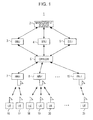
- FIG. 1 is a block diagram of a wireless communication system according to the present embodiment
- FIG. 2 is a process flowchart for the understanding of the operation condition of the wireless communication system
- FIG. 3 is a process flowchart illustrating the change of the operation condition of the wireless communication system
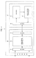
- FIG. 4 is a detailed block diagram of a management server
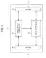
- FIG. 5 is a detailed block diagram of a BBU
- FIG. 6 is a detailed block diagram of a CPRISW
- FIG. 7 is a detailed block diagram of an RRH
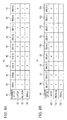
- FIGs. 8A and 8B are correspondence tables of the number of UEs performing wireless communication and the cell numbers assigned to each RRH and each BBU;
- FIGs. 9A to 9C are tables illustrating the relation of connection of each BBU and each RRH in accordance with the number of UEs;
- FIGs. 10A and 10B are schematic diagrams of an operation of the CPRISW in which a single BBU is coupled to a plurality of RRHs;
- FIG. 11 is a block diagram illustrating an operation of the wireless communication system in which the number of UEs communicating with each RRH is small;
- FIG. 12 is a process flowchart illustrating a shift from a state in which the operation control is stopped to a state in which the operation control is executed;
- FIGs. 13A and 13B are schematic diagrams of cell ranges covered by each of the RRHs and the cell numbers assigned to the cells;
- FIG. 14 is a block diagram illustrating an operation of the wireless communication system in which no UE exists in a cell range covered by an RRH;
- FIG. 15 is a process flowchart illustrating a shift from a state in which the operation control is stopped to a state in which the operation control is executed;
- FIGs. 16A and 16B are schematic diagrams of cell ranges covered by each RRH, and the cell number assigned to each cell;
- FIGs. 17A and 17B are detailed block diagrams of a device in which a global positioning system (GPS) is used in the wireless communication system.
- GPS global positioning system
- FIG. 18 is a process flowchart of the operation control in consideration of synchronization by the GPS.
- FIG. 1 is a block diagram of a wireless communication system 1 according to the present embodiment.
- the wireless communication system 1 includes a management server 2, BBUs 3, 4 and 5, a CPRI switch (CPRISW) 6, RRHs 7 to 15 and UEs 16 to 25.
- the wireless communication system 1 includes three BBUs, nine RRHs and ten UEs., but the number of BBU, RRH and UE which constitute the wireless communication system 1 is not limited thereto.
- the management server 2 monitors the operation rate of each device of the wireless communication system 1 and the relation of connection among the devices.
- the management server 2 is an example of a controller which performs power supply management of each device and switch control of the relation of connection among the devices in accordance with the operation rate of each device and the monitoring result of the relation of connection.
- the BBUs 3, 4 and 5 are examples of baseband processors which perform baseband signal processing of the base station.
- a single BBU is capable of performing baseband signal processing from up to three RRHs. Power supply of each BBU is capable of being turned on and off by a control signal from the management server 2.
- the number of BBUs is three in the present embodiment but the number of BBU is not limited thereto.
- a single BBU includes a baseband signal processor which may separately process a baseband signal from three RRHs.
- the CPRISW 6 is an example of a switch which switches connection between each BBU and each RRH. Switching operation by the CPRISW 6 is controlled by the management server 2.
- the CPRISW 6 copies a packet signal received from a single BBU in accordance with the connection state and transmits the copied packet signal to a plurality of RRHs. Also, the CPRISW 6 adds the packet signal received from the plurality of RRHs and transmits to the added packet signal to a single BBU.
- the RRHs 7 to 15 convert the packet signal received from any of the BBUs into a wireless signal.
- Each RRH is an example of the wireless unit which transmits the converted wireless signal to each UE.
- Each RRH receives the wireless signal from each UE.
- Each RRH includes a specific area in which the RRH is capable of communicating with each UE. The specific area is determined by the signal amplification capability of the RRH and the directivity of an antenna. The specific area is called a cell. The identification number provided to the cell is called a cell number.
- the UEs 16 to 25 are examples of mobile terminals which transmit and receive the wireless signal.
- Each UE is a mobile terminal capable of performing wireless communication with any of the RRHs.
- the cell to which each UE belongs is determined by the positional relationship with each RRH.
- Each UE has an operation condition and an amount of communication data which are different from those of other RRHs.
- FIG. 2 is a process flowchart for the understanding of the operation condition of the wireless communication system 1.
- Each UE has an identification number assigned for the identification thereof.
- the management server 2 manages the identification number of each UE together with the cell number assigned to each UE.
- Each UE periodically transmits, to the RRH, the traffic amount information representing its own traffic amount together with its own identification number (51).
- Each RRH which received the traffic amount information and the identification number of each UE transmits the received information to the CPRISW 6 (S2).
- the CPRISW 6 transmits the traffic amount information and the identification number received from each RRH to the BBU designated as a connection destination by the management server 2 (S3).
- Each BBU notifies the traffic amount information and the identification number of each UE received from each RRH to the management server 2 (S4).
- the management server 2 totals the traffic amount processed by each RRH and each BBU in accordance with the received information (S5).
- the management server 2 totals the number of UEs under communication with each RRH in accordance with the identification number of each UE (S6).
- the management server 2 calculates the operation rate of each RRH and each BBU in accordance with the traffic amount and the number of UEs which are totaled.
- the management server 2 calculates the operation rate in accordance with the ratio between the traffic amount and the number of UEs processable by each RRH and each BBU and the current traffic amount and the current number of UEs (S7).
- the management server 2 determines whether each RRH and each BBU are to operate or to stop in accordance with the calculated operation rate (S8).
- the EMS monitors the traffic amount. Determining whether each RRH and each BBU are to operate or to stop in accordance with the operation rate includes determining whether each RRH and each BBU are to operate or to stop in accordance with the operation determination table which will be described later.
- the management server 2 is capable of determining whether each RRH and each BBU which constitute the wireless communication system 1 are to operate or to stop in accordance with the traffic amount information and the identification number of each UE.
- FIG. 3 is a process flowchart illustrating the change of the operation condition of the wireless communication system 1.
- the management server 2 switches between the operation and stop of each RRH and each BBU which constitute the wireless communication system 1 in accordance with the operation state of the wireless communication system 1 obtained by the process of FIG. 2 .
- Switching between the operation and stop is performed by the SON of the management server 2.
- the SON switches between the operation and stop of each RRH and each BBU in accordance with the operation state monitored by the EMS.
- the management server 2 determines whether the BBU and the RRH are to operate or to stop in accordance with the monitoring result of the EMS (S10). Determination about operation and stop of each BBU and each RRH is made in accordance with the monitoring result of the EMS and an operation determination table which will be described later. Details of the operation determination table will be described later.
- the management server 2 determines the cell number to be assigned to the cell covered by an operating RRH in accordance with the monitoring result and the operation determination table of the EMS.
- the cell is a range in which a single RRH transmits radio waves to the UE.
- the management server 2 assigns a single frequency to a single cell number.
- the cell Since each cell number is assigned with a frequency which is different from those of other cell numbers, the cell is capable of performing wireless communication with the RRH to which the cell number to which the UE belongs has been assigned even if the UE exists in an area covered by a plurality of cells with different cell numbers.
- the management server 2 notifies the determined cell number to each BBU (S11).
- Each BBU notifies the received cell number to each UE via each RRH (S12).
- Each UE changes the cell number autonomously by the execution of a compulsory handover after a certain period of time elapsed. Previous notification allows each UE to start the handover to a new cell number before the switching operation of the operational state of each BBU and each RRH is performed.
- the management server 2 transmits, to the CPRISW 6, a switching signal used for the switching of each RRH which is the connection destination of each BBU in accordance with determination result in step S11 (S13).
- the CPRISW 6 performs switching operation of connection simultaneously with the cell number change notification which will be described later in accordance with the switching signal received from the management server 2.
- the management server 2 outputs a control signal for the instruction to operate or to stop each BBU and each RRH in accordance with the determination result in step S11 (S14).
- Each BBU which received the control signal determines to operate or to stop in accordance with the control signal (S15).
- Each RRH which received the control signal determines to operate or to stop in accordance with the control signal (S16).
- the management server 2 After the notification of the changed cell number to each BBU and each UE, the management server 2 outputs a cell number change notification signal to each BBU and each RRH (S17).
- each BBU and each RRH which received the cell number change notification signal are set to have the new cell numbers and the CPRISW 6 switches the connection (S18).
- Each BBU and each RRH operate or stop in accordance with the control signal.
- the cell number change notification in step S17 may be performed by a packet signal which has a frame number notified to, for example, each BBU, the CPRISW 6 and each RRH at the time of notification of the cell number in step S11.
- each BBU and each RRH are capable of receiving a packet signal which includes the frame number and thereby performing the switching operation to the new cell number.
- the CPRISW 6 receives the packet signal which includes the frame numbers and, simultaneously, performs the switching operation of connection.
- each BBU, the CPRISW 6 and each RRH include an own storage unit which stores the notified frame number.
- the following embodiments have the same configuration.
- a counter may be mounted on each BBU, the CPRISW 6 and each RRH in order to count a difference value between the current frame number and the frame number at the time of switching operation to the new cell number.
- the switching operation to the new cell number may be performed simultaneously.
- Synchronously counting up of the counter of CPRISW 6 allows the synchronous switching operation of connection.
- each BBU, the CPRISW 6 and each RRH include own counter to count the time before the switching takes place.
- the management server 2 is capable of changing the operation state of the wireless communication system 1 in accordance with the monitoring result of the EMS.
- FIG. 4 is a detailed block diagram of the management server 2.
- the management server 2 includes an EMS 40 and an SON 41.
- the EMS 40 monitors the traffic amount of the wireless communication system 1.
- the SON 41 outputs a control signal used to change the operation state of each RRH and each BBU which constitute the wireless communication system 1 in accordance with the monitoring result of the EMS 40.
- the EMS 40 includes an HWY-INF 42, a monitoring controller 43 and an SON-INF 44.
- the HWY-INF 42 is an interface for the communication with each BBU.
- the monitoring controller 43 monitors the traffic information received from the HWY-INF 42.
- the monitoring controller 43 transmits the monitoring result of the traffic information to the SON-INF 44.
- the SON-INF 44 is an interface for the communication with SON 41.
- the SON-INF 44 transmits the monitoring result received from the monitoring controller 43 to the SON 41.
- the SON 41 includes a SON-INF 45, a database 46 and a base station controller 47.
- the SON-INF 45 is an interface for the communication with the EMS 40.
- the SON-INF 45 receives the monitoring result of the traffic information from the EMS 40.
- the SON-INF 45 transmits the received monitoring result to the database 46.
- the database 46 stores the operation determination table which will be described later. The database 46 determines whether the operation of each BBU and each RRH is to continue or to stop in accordance with the monitoring result and the operation determination table received from the SON-INF 45. Similarly, the database 46 determines the cell number of each BBU in accordance with the monitoring result and the operation determination table. The database 46 outputs the determined operation state and cell number of the BBU and the RRH to the base station controller 47.
- the base station controller 47 outputs a control signal of each BBU, the CRPRISW 6, each RRH and each UE to the SON-INF 45 in accordance with the operation state and the cell number of the BBU and the RRH received from the database 46.
- the control signal is output at the time illustrated in the above-described process flowchart.
- the SON-INF 45 outputs the received control signal to the EMS 40.
- the EMS 40 outputs the received control signal to each BBU.
- the management server 2 is capable of controlling the operation state and the cell number to be assigned of each BBU, each RRH and each UE in accordance with the operation state of the wireless communication system 1.
- FIG. 5 is a detailed block diagram of the BBU 3.
- BBUs 4 and 5 are the same in function and configuration. Therefore, only the BBU 3 will be described below.
- the BBU 3 changes the operational state and the cell number in accordance with the control signal received from the management server 2.
- the BBU 3 includes a BBU-INF 50, a power supply controller 51, a signal processor 52 and an HWY-INF 53.
- the BBU-INF 50 is an interface for the communication with each RRH in accordance with the CPRI standard.
- the BBU 3 is coupled to the CPRISW 6 via the BBU-INF 50.
- the BBU-INF 50 transmits the signal received from the CPRISW 6 to the power supply controller 51 or to the signal processor 52.
- the power supply controller 51 controls the power supply to the signal processor 52 in accordance with the control signal received from the management server 2.
- the power supply controller 51 stops the power supply to the signal processor 52 when the control signal instructing to stop the operation of the BBU 3 is received.
- the power supply controller 51 continues the operation even when the power supply to the signal processor 52 is stopped. If the control signal instructing to start the operation of the BBU 3 from the management server 2 is received while the operation of the BBU 3 is stopped, the power supply controller 51 starts the power supply to the signal processor 52.
- an operation request of the BBU 3 from the management server 2 may be responded by letting only the power supply controller 51 which is controllable by the management server 2 operate separately from the BBU 3.
- the power supply controller 51 transfers the control signal received from the management server 2 to the BBU-INF 50 if the control signal is not for the BBU 3.
- the control signal transferred to the BBU-INF 50 is transmitted to each RRH.
- the management server 2 is capable of transmitting the control signal to each RRH even when the operation of the signal processor 52 is stopped.
- the signal processor 52 performs baseband processing, such as modulation and demodulation, of the signals received from each RRH or the management server 2.
- the signal processor 52 adds the signal other than the information source to the transmitted signal in the wireless signal transmission to each UE.
- Examples of the signals other than the information source include an error control code and a signal specifying the destination of the communication.
- the signal processor 52 separates the signal other than the information source about the received signal in the reception of the wireless signal from each UE.
- the HWY-INF 53 is an interface for the communication with the management server 2.
- the HWY-INF 53 transmits the control signal received from the management server 2 to the power supply controller 51.
- the HWY-INF 53 transmits the signal received from the management server 2 to the signal processor 52.
- the HWY-INF 53 transmits the control result received from the power supply controller 51 to the management server 2.
- the HWY-INF 53 transmits the signal received from the signal processor 52 to the management server 2.
- a single BBU is capable of executing data communication with three RRHs.
- a single BBU may have three configurations which is illustrated in FIG. 5 in the same device, or may have three signal processors 52.
- the BBU 3 is capable of continuing or stopping the power supply to the signal processor 52 in accordance with the control signal received from the management server 2.
- FIG. 6 is a detailed block diagram of the CPRISW 6.
- the CPRISW 6 switches the relation of connection of each BBU and each RRH in accordance with the control signal received from the management server 2.
- the CPRISW 6 includes a BBU-INF 61, a switch controller 62, a switch processor 63 and an RRH-INF 64.
- the BBU-INF 61 is an interface for the communication with each BBU.
- the BBU-INF 61 transmits the control signal received from each BBU to the switch controller 62.
- the BBU-INF 61 transmits the signal received from each BBU to the switch processor 63.
- the BBU-INF 61 transmits the signal received from the switch processor 63 to each BBU.
- the switch controller 62 switches the relation of connection of the switch processor 63 in accordance with the received control signal.
- the switch processor 63 switches the relation of connection of the BBU-INF 61 and the RRH-INF 64 in accordance with the switching signal received from the switch controller 62. Details of the switching operation of the switch processor 63 will be described later.
- the RRH-INF is an interface for the communication with each RRH.
- the RRH-INF 64 transmits the signal received from the switch processor 63 to each RRH.
- the RRH-INF 64 transmits the signal received from each RRH to the switch processor 63.
- the BBU-INF 61 transmits the signal received from the switch processor 63 to each BBU. Details of the switching operation of the CPRISW 6 illustrated in FIG. 6 will be described later.
- FIG. 7 is a detailed block diagram of the RRH 7.
- RRHs 8 to 15 are the same in function and configuration. Therefore, only the RRH 7 will be described below.
- the RRH 7 changes the operational state and the cell number in accordance with the control signal received from the management server 2.
- the RRH 7 includes an RRH-INF 70, a power supply controller 71, a radio frequency (RF) processor 72 and an ANT-INF 73.
- RF radio frequency
- the RRH-INF 70 is an interface for the communication with each BBU in accordance with the CPRI standard.
- the RRH 7 is coupled to the CPRISW 6 via the RRH-INF 70.
- the RRH-INF 70 transmits the signal received from the CPRISW 6 to the power supply controller 71 or to the RF processor 72.
- the power supply controller 71 controls the power supply to the RF processor 72 in accordance with the control signal received from the management server 2.
- the power supply controller 71 stops the power supply to the RF processor 72 when the control signal instructing to stop the operation of the RRH 7 is received.
- the power supply controller 71 continues the operation even when the power supply to the RF processor 72 is stopped. If the control signal instructing to start the operation of the RRH 7 from the management server 2 is received while the operation of the RRH 7 is stopped, the power supply controller 71 starts the power supply to the RF processor 72.
- the RF processor 72 performs RF processing of the signal received from each UE or any of the BBUs. During the wireless signal transmission to each UE, the RF processor 72 converts the carrier frequency of the information source received from the BBU from the baseband region into the RF region. The frequency band of the RF region is determined in accordance with the cell number assigned to the RRH 7. The RF processor 72 transmits the information source converted into the RF region to each UE as a radio wave. During the wireless signal reception from each UE, the RF processor 72 converts the carrier frequency of the information source received from each UE from the RF region into the baseband region. The RF processor 72 transmits the information source which has been converted into the baseband region to any of the BBUs via a cable.
- the ANT-INF 73 is an interface for the wireless communication with each UE.
- the ANT-INF 73 transmits the information source received from the RF processor 72 to an antenna.
- the ANT-INF 73 transmits the information source received from the antenna to the RF processor 72.
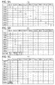
- FIGs. 8A and 8B are correspondence tables of the number of UEs performing wireless communication and the cell numbers assigned to each RRH and each BBU.
- FIGs. 8A and 8B are illustrative and are not restrictive.
- the database 46 of the management server 2 stores the correspondence table illustrated in FIGs. 8A and 8B as a part of the operation determination table.
- FIG. 8A is a table 80 for the reference of the cell numbers assigned to each RRH in accordance with the number of UEs performing wireless communication.
- FIG. 8B is a table 81 for the reference of the cell numbers assigned to each BBU in accordance with the number of UEs performing wireless communication.
- the management server 2 changes the cell number assigned to each RRH in accordance with the number of UEs performing wireless communication and with the traffic amount.
- the RRHs may be assigned to a single BBU. Therefore, the management server 2 is capable of reducing the number of operating BBUs.
- the reduced number of operating BBUs allows the management server 2 to reduce power consumption of the wireless communication system 1.
- the cell area covered by a single cell may be enlarged.
- the enlarged cell area allows the reduction of the number of handovers accompanying the movement of the UE.
- the reduced number of handovers allows the lessening of the process load relating to the wireless communication system 1.
- the table 80 illustrated in FIG. 8A is stored in the database 46 of the management server 2.
- the rows of the table 80 represent the cell numbers to be assigned to the RRHs in accordance with the number of UEs under communication.
- the row 82 represents the thresholds used to determine whether the number of UEs is large, medium or small. The thresholds are set in advance in accordance with the throughput of each RRH, the cell size and other factors.
- the row 83 represents the cell number assigned to the RRH 7 in accordance with the number of UEs under communication. For example, the RRH 7 in the present embodiment always has the cell number'1' regardless of the number of UEs.
- the row 91 represents the cell number assigned to the RRH 15 in accordance with the number of UEs under communication. The RRH 15 has the cell number '9' when the number of UEs is large, '3' when the number of UEs is medium and '1' when the number of UEs is small.
- the columns of the table 80 represent the cell numbers assigned to the RRHs among the number of UEs under communication.
- the column 92 represents the cell numbers assigned to the RRHs when the number of UEs is large. Different cell numbers, namely '1' to '9,' are assigned to the RRHs.
- the column 93 of the table 80 represents the cell number assigned to the RRHs when the number of UEs is medium.
- the cell number '1' is assigned to the RRHs 7, 8 and 9, the cell number '2' is assigned to the RRHs 10, 11 and 12 and the cell number '3' is assigned to the RRhis 13, 14 and 15.
- the same cell number may be assigned to a plurality of RRHs when the cell number is assigned such that the number of UEs existing in the area to which a single cell number has been assigned does not exceed the number of UEs processable by a single BBU.
- the column 94 of the table 80 represents the cell numbers assigned to the RRHs when the number of UEs is small.
- the cell number'1' is assigned to all the RRH.
- the same cell number may be assigned to the larger number of RRHs when the cell number is assigned such that the number of UEs existing in the area to which a single cell number has been assigned does not exceed the number of UEs processable by a single BBU.
- the cell area covered by a single cell may be enlarged.
- the enlarged cell area allows the reduction of the number of handovers accompanying the movement of the UE.
- the reduced number of handovers allows to lessen the process load relating to the wireless communication system 1.
- the table 81 illustrated in FIG. 8B is stored in the database 46 of the management server 2.
- the rows of the table 81 represent the cell numbers to be assigned to the BBUs in accordance with the number of UEs under communication and the operational states.
- three units which perform data communication with the RRHs are mounted on a single BBU.
- a single BBU is capable of performing data communication with up to three RRHs.
- the units mounted on the BBU 3 are called a BBU 3-1, a BBU 3-2 and a BBU 3-3.
- the rows 95 of the table 81 represent the thresholds used to determine whether the number of UEs is large, medium or small.
- the thresholds are set in advance in accordance with the throughput of each RRH, the cell size and other factors.
- the thresholds in the row 95 are the same as those in the row 82.
- the row 96 represents the cell number assigned to the BBU 3-1 in accordance with the number of UEs under communication. For example, the BBU 3-1 always has the cell number of '1' regardless of the number of UEs; this means that the BBU 3-1 is always operating.
- the row 104 represents the cell number assigned to the BBU 5-3 in accordance with the number of UEs under communication.
- the BBU 5-3 has the cell number of '9' when the number of UEs is large; this means that the BBU 5-3 stops the operation when the number of UEs is medium or smaller.
- the columns of the table 81 represent the cell numbers assigned to the BBUs among the number of UEs under communication and the operational states.
- the column 105 represents the cell numbers assigned to the BBUs when the number of UEs is large and the operational states. Different cell numbers, namely '1' to '9,' are assigned to the BBUs.
- the column 106 of the table 81 represents the cell number assigned to the BBUs when the number of UEs is medium.
- the cell number'1' is assigned to the BBU 3-1
- the cell number '2' is assigned to BBU 3-2
- the cell number '3' is assigned to the BBU 3-3. Operations of the BBUs 4 and 5 are stopped.
- the same cell number is assigned to the three RRHs when the number of UEs is medium in the table 81.
- a single BBU is capable of processing the baseband processing of the data output from the three RRHs to which the same cell number has been assigned.
- the number of the cell numbers becomes small as the same cell number is assigned to the larger number of RRHs. Therefore, the number of BBUs which are to be operated may be reduced.
- the column 107 of the table 81 represents the cell number assigned to the BBUs when the number of UEs is small.
- the cell number'1' is assigned to the BBU 3-1.
- the table 80 shows that the cell number '1' is assigned to all the RRHs when the number of UEs is small. Therefore, it is possible to let only the BBU 3-1 operate and let the rest of the BBUs stop when the number of UEs is small.
- the number of operating BBUs may be changed by the change of the number of RRHs to which the same cell number is assigned as the number of UEs performing data communication changes.
- the change in the number of operating BBUs may optimize power consumption of the entire wireless communication system 1 in accordance with the traffic amount of data.
- FIGs. 9A to 9C are tables illustrating the relation of connection of each BBU and each RRH in accordance with the number of UEs.
- FIG. 9A is a table 110 illustrating the relation of connection of the BBUs and the RRHs when the number of UEs is large.
- FIG. 9B is a table 111 illustrating the relation of connection of the BBUs and the RRHs when the number of UEs is medium.
- FIG. 9C is a table 112 illustrating the relation of connection of the BBUs and the RRHs when the number of UEs is small.
- the tables 110, 111 and 112 are stored in the database 46 of the management server 2.
- the switch controller 62 of the CPRISW 6 described above retrieves either of the table 110, 111 or 112 in accordance with the number of UEs.
- the switch controller 62 switches the relation of connection of the switch processor 63 in accordance with the retrieved table.
- the white circles in the table 110 represent the relation of connection of each RRH and each BBU.
- the white circles work in the same way in the tables 111 and 112.
- the switch controller 62 refers to the table 110 to control the switch processor 63 such that the RRH 7 and the BBU 3-1 are coupled when the number of UEs is large. Connections between other BBUs and RRHs are made in the similar manner.
- the switch controller 62 refers to the table 111 to control the switch processor 63 such that the RRHs 7, 8 and 9 and the BBU 3-1 are coupled when the number of UEs is medium. Connections regarding the rows of BBU 3-2 and the BBU 3-3 are made in the same manner.
- the column of 'addition' of table 111 represent the set of RRHs which are added and transmitted to each of the BBUs when the data is transmitted from the RRHs to the BBUs.
- the row of the BBU 3-1 in the column of 'addition' is filled with 'RRHs 7, 8 and 9'. Therefore, when the data is transmitted to the BBU 3-1 from the RRH, the switch controller 62 controls the switch processor 63 to add the data output from each of the RRHs 7, 8 and 9.
- the switch processor 63 transmits the added result to the BBU 3-1. Connections regarding the rows of BBU 3-2 and the BBU 3-3 are made in the same manner. Power supply to the BBUs which are coupled with no RRHs may be stopped.
- the switch controller 62 refers to the table 112 to control the switch processor 63 such that the RRHs 7, 8 and 9 and the BBU 3-1 are coupled when the number of UEs is small. Power supply to the BBUs which are coupled with no RRHs may be stopped.
- the column of 'addition' in the table 112 represents a set of RRH which are added and transmitted to each BBU when the data is transmitted from the RRH to the BBU.
- the row of BBU 3-1 of the column of 'addition' is filled with 'total addition'. Therefore, when data is transmitted to the BBU 3-1 from the RRH, the switch controller 62 controls the switch processor 63 to add the data output from all the RRHs. The switch processor 63 transmits the added result to the BBU 3-1.
- the CPRISW 6 is capable of switching connections suitably in accordance with the operational state of the BBU and the RRH with reference to the tables 110, 111 and 112 in accordance with the number of UEs.
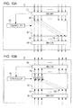
- FIGs. 10A and 10B are schematic diagrams of an operation of the CPRISW 6 in which a single BBU is coupled to the RRH S .
- FIG. 10A is a schematic diagram of the operation of the CPRISW 6 during data transmission from the BBU to the RRH.
- FIG. 10B is a schematic diagram of the operation of the CPRISW 6 during data transmission from the RRH to the BBU.
- the switch controller 62 illustrated in FIG. 10A controls the switch processor 63 to connect a port of a signal 120, a port of a signal 121 and a port of a signal 120 and a port of a signal 122.
- the switch processor 63 reproduces the received signal 120 and outputs the signal 120 as the signals 121 and 122.
- the output signals 121 and 122 are separately input to the RRHs.
- the RRHs which receive the signals 121 and 122 have the same cell number. Each RRH receives the same signal from the BBU. If the UE exists in an area covered by any of the RRHs, the UE is capable of receiving the signal transmitted from the BBU.
- the switch controller 62 illustrated in FIG. 10B controls the switch processor 63 to add the signal 121 to the signal 122 and then output the signal 120.
- the signals 121 and 122 are output from the RRH which covers adjoining cells.
- the RRHs which output the signals 121 and 122 have the same cell number assigned thereto. Therefore, if the UE, which exists in an area covered by any of the RRHs, the BBU is capable of receiving the signal transmitted from the UE. Since RRHs have the cell number assigned thereto, communication may be continued without the need of handover if the UE enters an area covered by a different RRH.
- the switch processor 63 is capable of add and amplify the signals 121 and 122, and then output the signal 120.
- the addition and amplification increases the amplitude and therefore the BBU is capable of decreasing the error rate of the signal being received.
- FIG. 11 is a block diagram illustrating an operation of the wireless communication system 1 in which the number of UEs communicating with each RRH is small. As illustrated in FIG. 11 , the RRH 7 communicates only with the UE 16. An RRH 8 communicates only with the UE 20. An RRH 15 communicates only with the UE 25. If the number of UEs communicating with each RRH decreases and the number of UEs is medium or smaller, power supply to the BBUs 4 and 5 is stopped. The hatching in FIG. 11 represents that the power supply to the BBUs 4 and 5 is stopped.
- FIG. 12 is a process flowchart illustrating a shift from a state in which the operation control is stopped to a state in which the operation control is executed.
- the state in which the operation control is stopped refers to a state in which all the devices of the wireless communication system 1 are operating without any operation control.
- the state in which the operation control is executed refers to a state in which the operation of each device is controlled to continue or stop in accordance with the operational state of the wireless communication system 1.
- Step S20 represents that all the RRHs and BBUs are operating. If the number of UEs under communication in the wireless communication system 1 decreases, the information indicating the decrease is notified to the management server 2 (S21). The management server 2 starts the operation control in accordance with the number of UEs (S22).
- the management server 2 notifies the cell number after the connection change to each BBU (S23).
- the management server 2 notifies the cell number after the connection change to each UE via the BBU (S24).
- Each UE changes the cell number autonomously by the execution of a compulsory handover after a certain period of time elapsed. Previous notification allows each UE to start the handover to a new cell number before the switching operation of the operational state of each BBU and each RRH is performed.
- the management server 2 transmits the switching signal to the CPRISW 6 for the instruction of the switching operation of connection (S25).
- the CPRISW 6 performs switching operation of connection simultaneously with the cell number change notification which will be described later in accordance with the switching signal received from the management server 2.
- the management server 2 outputs a control signal for the instruction to operate or to stop each BBU in accordance with the determination in step S22 (S26).
- Each BBU which received the control signal determines to operate or to stop in accordance with the control signal.
- the management server 2 After a certain period of time elapsed since the changed cell numbers are notified to each BBU and each UE, the management server 2 outputs a cell number change notification signal to each BBU and each RRH (S27). After a certain period of time elapsed since the notification of the cell numbers in step S23, the new cell number is assigned to each UE and, at the same time, the new cell numbers are assigned to each BBU and each RRH which received the cell number change notification signal (S28). The CPRISW 6 switches the connection. Each BBU and each RRH operate or stop in accordance with the control signal.
- the management server 2 switches the relation of connection of the BBU and the RRH in accordance with the decrease in the number of UEs.
- the management server 2 is capable of reducing the power consumption of the entire wireless communication system 1 by stopping the power supply to the BBUs which are unnecessary as a result of the switching operation of the relation of connection.
- FIGs. 13A and 13B are schematic diagrams of cell ranges covered by each of the RRHs and the cell numbers assigned to the cells.
- FIG. 13A is a schematic diagram of the cell numbers when the number of UEs is medium.
- FIG. 13B is a schematic diagram of the cell numbers when the number of UEs is small.
- the cell ranges covered by the RRHs 7, 8 and 9 are adjacent to one another.
- the cell number assigned to the RRHs 7, 8 and 9 is 1. Therefore, the wireless communication system 1 is capable of enlarging the cell range covered by a single cell number by assigning the same cell number to three RRHs as compared with a case in which an individual cell number is assigned to each RRH.
- the enlarged cell range covered by a single cell number may reduce the number of handovers due to the change in cell number accompanying the movement of the UE. This is also possible in the RRHs 10 and 11 to which the cell number '2' is assigned and the RRHs 13 and 14 to which the cell number '3' is assigned.
- the same cell number '1' is assigned to the cell range covered by all the RRHs when the number of UEs is small. Therefore, the cell range covered by the same cell number is larger than the cell range when the number of UEs is medium.
- the larger the cell range covered by the same cell number the smaller the change rate of the cell number accompanying the movement of the UE.
- the smaller change rate of the cell number produces the load which is smaller than that accompanying the handover in the wireless communication system 1.
- the baseband processing in the wireless communication with the UEs to which the same cell number is assigned may be processed by a single BBU. Therefore, when the number of UEs is small, the baseband processing in the wireless communication with all the UEs covered by the wireless communication system 1 may be performed by a single BBU.
- the wireless communication system 1 is capable of reducing the power consumption by decreasing the number of BBUs necessary for the process and stopping the power supply to the unnecessary BBUs.
- FIG. 14 is a block diagram illustrating an operation of the wireless communication system when no UE exists in a cell range covered by an RRH.
- the RRH 7 communicates only with the UE 16.
- An RRH 8 communicates with no UEs.
- An RRH 15 communicates only with the UE 25. If no UEs exist in the cell range covered by the RRH 8, the operation of the RRH 8 is stopped for the decrease in the power consumption.
- the operation of the BBUs 4 and 5 is stopped when the number of UEs communicating with each RRH decreases and the number of UEs is medium or smaller.
- the hatching in FIG. 14 represents that the operation of the BBUs 4 and 5 and the RRH 8 is stopped.
- FIG. 15 is a process flowchart illustrating a shift from a state in which the operation control is stopped to a state in which the operation control is executed.
- Step S30 represents that all the RRHs and BBUs are operating. If the number of UEs under communication in the wireless communication system 1 decreases, the information indicating the decrease is notified to the management server 2 (S31).
- the management server 2 starts the operation control in accordance with the number of UEs.
- the management server 2 determines whether the operation of the BBU and the RRH is to continue or to stop (S32).
- the management server 2 determines the cell numbers to be assigned to each BBU, each RRH and each UE after the operation control.
- the management server 2 notifies the determined cell number to each BBU (S33).
- the management server 2 notifies determined cell number to each UE via the BBU (S34).
- Each UE changes the cell number autonomously by the execution of a compulsory handover after a certain period of time elapsed. Previous notification allows each UE to start the handover to a new cell number before the switching operation of the operational state of each BBU and each RRH is performed.
- the management server 2 transmits, to the CPRISW 6, a switching signal used for the switching of each RRH which is the connection destination of each BBU in accordance with determination result in step S32 (S35).
- the CPRISW 6 performs switching operation of connection simultaneously with the cell number change notification which will be described later in accordance with the switching signal received from the management server 2.
- the management server 2 outputs a control signal for the instruction to operate or to stop each BBU in accordance with the determination in step S32 (S36). Each BBU which received the control signal determines to operate or to stop in accordance with the control signal.
- the management server 2 outputs a control signal for the instruction to operate or to stop each RRH in accordance with the determination in step S32 (S37). Each RRH which received the control signal determines to operate or to stop in accordance with the control signal.
- the management server 2 After a certain period of time elapsed since the changed cell numbers are notified to each BBU and each UE, the management server 2 outputs cell number change notification signal to each BBU and each RRH (S38). After a certain period of time elapsed since the notification of the cell numbers in step S33, the new cell number is assigned to each UE and, at the same time, the new cell numbers are assigned to each BBU and each RRH which received the cell number change notification signal (S39). At the same time, the CPRISW 6 switches the connection. Each BBU and each RRH continue or stop the operation in accordance with the control signal.
- the management server 2 switches the relation of connection of the BBU and the RRH in accordance with the decrease in the number of UEs.
- the management server 2 is capable of reducing the power consumption of the entire wireless communication system 1 by stopping the power supply to the BBUs and RRHs which are unnecessary as a result of the switching of the relation of connection.
- FIGs. 16A and 16B are schematic diagrams of cell ranges covered by each of the RRHs and the cell numbers assigned to the cells.
- FIG. 16A is a schematic diagram of the cell numbers when the number of UEs is medium.
- FIG. 16B is a schematic diagram of the cell numbers when the number of UEs is small.
- FIG. 16A illustrates the cell ranges illustrated in FIG. 13A when power supply to the RRH 8 is stopped.
- FIG. 16B illustrates the cell ranges illustrated in FIG. 13B when power supply to the RRH 8 is stopped.
- the RRHs other than the RRH 8 are operating. Since the operation condition of the RRHs other than the RRH 8 is the same as that described with reference to FIG. 13A , description thereof will be omitted.
- the wireless communication system 1 is capable of further reducing the power consumption by decreasing the number of BBUs necessary for the process and stopping the power supply to the unnecessary BBUs and, at the same time, by stopping the power supply to the RRHs which are not in communication with the UEs.
- FIGs. 17A and 17B are detailed block diagrams of a device when a global positioning system (GPS) is used in the wireless communication system 1.
- FIG. 17A is a detailed block diagram of the BBU 3 when the GPS is used.
- FIG. 17B is a detailed block diagram of the CPRISVV 6 when the GPS is used.
- GPS global positioning system
- the configuration illustrated in FIG. 17A includes a GPS receiver 54 which is added to the BBU 3 illustrated in FIG. 5 .
- the GPS receiver 54 generates reference clocks in accordance with a received GPS signal.
- the signal processor 52 operates in accordance with the reference clocks generated by the GPS receiver 54.
- the wireless communication system 1 includes the BBUs.
- the BBUs operate asynchronously. When a single UE moves from a cell range managed by a certain BBU to a cell range managed by another BBU, handover occurs accompanying the change of the cell number. Asynchronous operation of the BBUs may cause interruption of data communication due to asynchronous operation timing of the BBUs during the handover.
- the GPS receiver 54 mounted on each BBU may synchronize the operation of the BBUs. The synchronized operation of the BBUs may prevent interruption of data communication during the handover.
- the configuration illustrated in FIG. 17B includes a counter 65 which is added to the CPRISW 6 illustrated in FIG. 6 .
- a switch control signal which the switch controller 62 receives includes information about frame numbers for the time of switching operation.
- the switch controller 62 calculates count values in accordance with the difference between the frame numbers at the time of receiving the switch control signal and the frame numbers at the time of switching.
- the switch controller 62 transmits the calculated count values to the counter 65.
- the counter 65 starts counting up upon reception of the count values.
- the counter 65 transmits a notification signal to the switch controller 62 when the counted-up value exceeds the received count value.
- the switch controller 62 which received the notification signal starts the switching with respect to the switch processor 63.
- the CPRISW 6 is capable of accurately performing the switching operation at the time of switching designated by the management server 2 by using the counter 65. Synchronous operation of the BBU which is a switch source and the BBU which is a switch destination achieved by the GPS receiver 54 may prevent instantaneous interruption of data communication accompanying the switching operation.
- the counter is used for the adjustment of the time of switching of the CPRISW 6 in the present embodiment; however, the following configuration is also possible: information about the frame numbers at the time of switching is stored in the switch controller 62 and the switching operation is started when the frame numbers received by the switch controller 62 exceed the frame numbers stored in the switch controller 62.
- FIG. 18 is a process flowchart of the operation control in consideration of synchronization by the GPS.
- the GPS receiver 54 of each BBU receives the GPS signal (S40).
- the GPS receiver 54 generates reference clocks in accordance with the received GPS signal.
- the BBUs, which receive the same GPS signal, may be synchronized.
- the synchronized BBUs output synchronization signals to the CPRISW 6, each RRH and each UE. Outputting the synchronization signals from the synchronized BBUs allows synchronization of the entire devices which constitutes the wireless communication system 1.
- the synchronized BBUs transmit identification information and traffic amount information to the management server 2 (S42).
- the management server 2 determines whether each BBU and each RRH is to operate or to stop in accordance with the received identification information and the traffic amount information (S43).
- the management server 2 determines the cell number to be assigned to each BBU, each RRH and each UE in accordance with the monitoring result of the EMS and the operation determination table.
- the management server 2 notifies the determined cell number to each BBU (S44).
- the management server 2 notifies each UE, via the BBU, of the determined cell number together with the frame number at the time of switching (S45).
- Each UE changes the cell number autonomously by the execution of compulsory handover at the timing at which the notified frame number is received. Previous notification allows each UE to start the handover to a new cell number before the switching operation of the operational state of each BBU and each RRH is performed. Since synchronization is achieved by the synchronization signals from the BBUs, handover of each UE may be performed at the same time as the switching operation of each BBU.
- the management server 2 transmits, to the CPRISW 6, a switching signal together with the frame number at which the switching operation is performed so as to instruct the switching operation of connection (S46).
- the switch controller 62 of the CPRISW 6 which received the switching signal switches the connection of the switch processor 63 in accordance with the instruction content.
- the management server 2 transmits, to each BBU, the control signal for the instruction to operate or stop each BBU at the time of transmitting the frame number at which the switching operation of the CPRISW 6 is performed (S47).
- the power supply controller 51 of each BBU which received the control signal lets the signal processor 52 operate or stop in accordance with the control signal.
- the management server 2 transmits, to the RRHs of which covering cell ranges have no UE under communication, the control signal for the instruction to operate or stop the RRH at the time of transmitting the frame number at which the switching operation of the CPRISW 6 is performed (S47).
- the power supply controller 71 of the RRH which received the control signal let the RF processor 72 operate or stop in accordance with the control signal.
- the management server 2 outputs a cell number change notification signal to each BBU and each RRH at the time of transmitting the frame number at which switching operation of the CPRISW 6 is performed (S48).
- the cell number of each UE is changed to a new cell number and each BBU and each RRH which received the cell number change notification signal obtain new cell numbers at the time of transmitting the frame number at which switching operation of the CPRISW 6 is performed (S49).
- the management server 2 switches the relation of connection of each BBU and each RRH, which are synchronized, at the time of transmitting the frame number at which switching operation of the CPRISW 6 is performed. Synchronization among the devices using the GPS signal allows the switching operation of the relation of connection of the wireless communication system 1 without any instantaneous interruption of the management server 2.
Applications Claiming Priority (1)
| Application Number | Priority Date | Filing Date | Title |
|---|---|---|---|
| JP2010284279A JP5614274B2 (ja) | 2010-12-21 | 2010-12-21 | 無線通信システム |
Publications (3)
| Publication Number | Publication Date |
|---|---|
| EP2469940A2 true EP2469940A2 (fr) | 2012-06-27 |
| EP2469940A3 EP2469940A3 (fr) | 2012-08-01 |
| EP2469940B1 EP2469940B1 (fr) | 2017-08-02 |
Family
ID=44905570
Family Applications (1)
| Application Number | Title | Priority Date | Filing Date |
|---|---|---|---|
| EP11186770.1A Not-in-force EP2469940B1 (fr) | 2010-12-21 | 2011-10-26 | Système de communication sans fil avec alimentation de puissance contrôlée d'une station de base |
Country Status (3)
| Country | Link |
|---|---|
| US (1) | US8937904B2 (fr) |
| EP (1) | EP2469940B1 (fr) |
| JP (1) | JP5614274B2 (fr) |
Cited By (3)
| Publication number | Priority date | Publication date | Assignee | Title |
|---|---|---|---|---|
| WO2015086945A1 (fr) * | 2013-12-13 | 2015-06-18 | Orange | Transport de données radio multipoint a multipoint |
| EP2898753A4 (fr) * | 2012-09-21 | 2016-06-22 | Ericsson Telefon Ab L M | N ud de réseau et procédé mis en uvre par un noeud de réseau pour commander la connectivité d'une unité radio distante à une unité en bande de base |
| CN105874861A (zh) * | 2014-11-29 | 2016-08-17 | 华为技术有限公司 | 一种调节空口容量密度的方法及装置 |
Families Citing this family (32)
| Publication number | Priority date | Publication date | Assignee | Title |
|---|---|---|---|---|
| US8976766B2 (en) * | 2011-12-07 | 2015-03-10 | Telefonaktiebolaget L M Ericsson (Publ) | Integrated microwave backhaul support in cellular products |
| EP2818002A4 (fr) * | 2012-02-24 | 2015-10-28 | Intel Corp | Réseau d'accès radio coopératif avec groupe de traitement d'unité de bande de base (bbu) de station de base centralisé |
| US9125047B2 (en) * | 2012-07-26 | 2015-09-01 | Nec Laboratories America, Inc. | Cloud-based radio access network for small cells |
| JP6082592B2 (ja) * | 2012-12-27 | 2017-02-15 | Kddi株式会社 | C−ranシステム、rrh装置、通信制御方法、およびコンピュータプログラム |
| KR102106809B1 (ko) * | 2013-08-05 | 2020-05-06 | 에스케이텔레콤 주식회사 | 신호경로절체장치 및 신호경로절체장치의 동작 방법 |
| JP6244736B2 (ja) * | 2013-08-16 | 2017-12-13 | 富士通株式会社 | 無線基地局装置および電力制御方法 |
| JP6194730B2 (ja) * | 2013-10-03 | 2017-09-13 | 富士通株式会社 | 無線局、及び、送信電力制御方法 |
| US10028132B2 (en) * | 2013-12-04 | 2018-07-17 | Lg Electronics Inc. | Method for transceiving system information in cloud wireless communication system and apparatus therefor |
| CN105993188B (zh) | 2014-02-14 | 2020-02-18 | 日本电气株式会社 | 网络控制设备、通信设备、网络控制方法、通信方法、通信系统和程序 |
| JP6267561B2 (ja) * | 2014-03-26 | 2018-01-24 | Kddi株式会社 | 制御装置、制御方法及びプログラム |
| EP3522401B1 (fr) | 2014-03-28 | 2020-11-18 | CommScope Technologies LLC | Gestion de puissance pour système d'antenne distribué |
| JP6401797B2 (ja) * | 2014-04-29 | 2018-10-10 | 華為技術有限公司Huawei Technologies Co.,Ltd. | 遠隔無線ユニットハブrhub、屋内通信システム、及び信号伝送方法 |
| US9516521B2 (en) * | 2014-07-28 | 2016-12-06 | Intel IP Corporation | Apparatus, system and method of transferring control of a remote radio head between base-band unit (BBU) processing pools |
| WO2016031101A1 (fr) * | 2014-08-28 | 2016-03-03 | 日本電気株式会社 | Appareil station de base radio, procédé d'affectation de ressources de traitement de cellules de station de base et support non temporaire lisible par ordinateur contenant un programme |
| US9680695B2 (en) | 2014-10-24 | 2017-06-13 | At&T Intellectual Property I, L.P. | Facilitating mobility dimensioning via dynamic configuration of a switch |
| US9954591B2 (en) * | 2015-01-16 | 2018-04-24 | RF DSP Inc. | Beamforming in a MU-MIMO wireless communication system |
| CN108141483B (zh) * | 2015-09-30 | 2020-11-03 | 康普技术有限责任公司 | 用于从电源向多个远程无线电头供电的电力线缆连接的装置 |
| US10608734B2 (en) | 2015-10-22 | 2020-03-31 | Phluido, Inc. | Virtualization and orchestration of a radio access network |
| JP6471244B2 (ja) * | 2015-11-20 | 2019-02-13 | エヌイーシー ラボラトリーズ ヨーロッパ ゲーエムベーハー | Sdnに支援されたシームレスなranアプリマイグレーション |
| CN107087306A (zh) * | 2016-02-12 | 2017-08-22 | 台扬科技股份有限公司 | 用于无线信源调度的方法 |
| US9999057B2 (en) * | 2016-09-01 | 2018-06-12 | Hon Hai Precision Industry Co., Ltd. | Resource allocation method of a wireless communication system and mechanism thereof |
| US10666501B2 (en) | 2016-09-15 | 2020-05-26 | At&T Intellectual Property, I, L.P. | Software defined network based CPRI switch for improved availability in cloud-based ran |
| CN108289300B (zh) * | 2017-01-10 | 2021-08-03 | 中兴通讯股份有限公司 | 一种支持分布式多场景的基站及其创建、通信方法 |
| WO2018198178A1 (fr) * | 2017-04-25 | 2018-11-01 | 富士通株式会社 | Dispositif de station de base sans fil, système et procédé de commutation d'unité sans fil |
| CN109286965A (zh) * | 2017-07-20 | 2019-01-29 | 中国移动通信有限公司研究院 | 分布式基站的休眠处理方法、网元实体及存储介质 |
| JP6970567B2 (ja) * | 2017-09-22 | 2021-11-24 | 株式会社日立国際電気 | 基地局装置及び無線通信システム |
| TWI669023B (zh) | 2018-07-17 | 2019-08-11 | 明泰科技股份有限公司 | 雲端無線存取網路系統及其控制方法 |
| TWI672054B (zh) | 2018-07-17 | 2019-09-11 | 明泰科技股份有限公司 | 雲端無線存取網路系統及其控制方法 |
| TWI729304B (zh) * | 2018-07-17 | 2021-06-01 | 明泰科技股份有限公司 | 雲端無線存取網路系統及其控制方法 |
| US11540170B2 (en) * | 2019-05-20 | 2022-12-27 | Commscope Technologies Llc | Load-testing a cloud radio access network |
| JP2021158602A (ja) * | 2020-03-27 | 2021-10-07 | 株式会社Nttドコモ | 無線通信システム、制御装置及び制御方法 |
| JP2022190884A (ja) * | 2021-06-15 | 2022-12-27 | 株式会社東芝 | 通信中継システムおよび無線装置 |
Citations (2)
| Publication number | Priority date | Publication date | Assignee | Title |
|---|---|---|---|---|
| JP2007274048A (ja) | 2006-03-30 | 2007-10-18 | Fujitsu Ltd | 無線通信装置及び無線ユニット |
| JP2010509816A (ja) | 2006-11-20 | 2010-03-25 | アルカテル−ルーセント | 無線セルラ屋内通信のための方法およびシステム |
Family Cites Families (8)
| Publication number | Priority date | Publication date | Assignee | Title |
|---|---|---|---|---|
| US6205133B1 (en) | 1996-11-25 | 2001-03-20 | Ericsson Inc. | Flexible wideband architecture for use in radio communications systems |
| CN1156186C (zh) | 2000-05-10 | 2004-06-30 | 株式会社Ntt都科摩 | 无线基站网络系统 |
| US6584330B1 (en) | 2000-07-18 | 2003-06-24 | Telefonaktiebolaget Lm Ericsson (Publ) | Adaptive power management for a node of a cellular telecommunications network |
| JP4417208B2 (ja) | 2004-09-10 | 2010-02-17 | 日本電信電話株式会社 | 光アクセスシステム、光サービスユニットおよび光ネットワークユニット |
| CN100426897C (zh) | 2005-01-12 | 2008-10-15 | 华为技术有限公司 | 分体式基站系统及其组网方法和基带单元 |
| US7787854B2 (en) | 2005-02-01 | 2010-08-31 | Adc Telecommunications, Inc. | Scalable distributed radio network |
| JP2006332937A (ja) * | 2005-05-25 | 2006-12-07 | Matsushita Electric Ind Co Ltd | 無線アクセスシステム |
| US20080214221A1 (en) | 2005-06-14 | 2008-09-04 | Mitsubishi Electric Corporation | Radio Base Station System |
-
2010
- 2010-12-21 JP JP2010284279A patent/JP5614274B2/ja not_active Expired - Fee Related
-
2011
- 2011-10-20 US US13/277,772 patent/US8937904B2/en not_active Expired - Fee Related
- 2011-10-26 EP EP11186770.1A patent/EP2469940B1/fr not_active Not-in-force
Patent Citations (2)
| Publication number | Priority date | Publication date | Assignee | Title |
|---|---|---|---|---|
| JP2007274048A (ja) | 2006-03-30 | 2007-10-18 | Fujitsu Ltd | 無線通信装置及び無線ユニット |
| JP2010509816A (ja) | 2006-11-20 | 2010-03-25 | アルカテル−ルーセント | 無線セルラ屋内通信のための方法およびシステム |
Cited By (9)
| Publication number | Priority date | Publication date | Assignee | Title |
|---|---|---|---|---|
| EP2898753A4 (fr) * | 2012-09-21 | 2016-06-22 | Ericsson Telefon Ab L M | N ud de réseau et procédé mis en uvre par un noeud de réseau pour commander la connectivité d'une unité radio distante à une unité en bande de base |
| US9578598B2 (en) | 2012-09-21 | 2018-01-02 | Telefonaktiebolaget L M Ericsson (Publ) | Network node and method performed by a network node for controlling connectivity of a radio resource unit to a base band unit |
| WO2015086945A1 (fr) * | 2013-12-13 | 2015-06-18 | Orange | Transport de données radio multipoint a multipoint |
| FR3015167A1 (fr) * | 2013-12-13 | 2015-06-19 | Orange | Systeme de transport de donnees radio multipoint a multipoint |
| US10680934B2 (en) | 2013-12-13 | 2020-06-09 | Orange | Multipoint-to-multipoint radio data transport |
| CN105874861A (zh) * | 2014-11-29 | 2016-08-17 | 华为技术有限公司 | 一种调节空口容量密度的方法及装置 |
| EP3217744A4 (fr) * | 2014-11-29 | 2017-11-15 | Huawei Technologies Co., Ltd. | Procédé et appareil de réglage de densité de capacité d'interface hertzienne |
| US10051482B2 (en) | 2014-11-29 | 2018-08-14 | Huawei Technologies Co., Ltd. | Method and apparatus for adjusting air interface capacity density |
| CN105874861B (zh) * | 2014-11-29 | 2019-05-28 | 华为技术有限公司 | 一种调节空口容量密度的方法及装置 |
Also Published As
| Publication number | Publication date |
|---|---|
| EP2469940A3 (fr) | 2012-08-01 |
| US8937904B2 (en) | 2015-01-20 |
| EP2469940B1 (fr) | 2017-08-02 |
| JP2012134708A (ja) | 2012-07-12 |
| US20120155446A1 (en) | 2012-06-21 |
| JP5614274B2 (ja) | 2014-10-29 |
Similar Documents
| Publication | Publication Date | Title |
|---|---|---|
| EP2469940B1 (fr) | Système de communication sans fil avec alimentation de puissance contrôlée d'une station de base | |
| US11368957B2 (en) | Remotely reconfigurable distributed antenna system and methods | |
| US8195225B2 (en) | Multimode communication terminal and multimode communication implementation method | |
| EP2299758B1 (fr) | Station d'émetteur/récepteur de base radio et procédé d'alimentation | |
| EP1259092B1 (fr) | Système de communication mobile | |
| US8983533B2 (en) | Multimode communication terminal and multimode communication implementation | |
| US7085564B2 (en) | Radio communication system, radio communication apparatus and radio communication method, and computer program | |
| EP1681772A1 (fr) | Dispositif et procédé pour l'usage efficient des antennes dans un terminal de communication mobile comprenant un module Bluetooth et un module de réseau local sans fil (WLAN) | |
| JP2007228213A (ja) | 移動通信システムにおける無線基地局の負荷制御方式 | |
| CN109565641A (zh) | 一种用于信标间隔适配的系统和方法 | |
| US11638178B2 (en) | Method and system for smart operating bandwidth adaptation during power outages | |
| US11374614B1 (en) | In-device coexistence for new radio | |
| AU2012374304B2 (en) | Technique for operating a network node in a heterogeneously deployed network | |
| CN105323858A (zh) | 一种分时长期演进系统中的频点切换方法、基站及系统 | |
| EP2840824A1 (fr) | Système de radiocommunication, station de base radio, et procédé de gestion des communications | |
| US20040127216A1 (en) | Electronic apparatus, radio communication apparatus, and dispatch electronic control method | |
| CN112188464A (zh) | 一种短波应急通信系统及方法 | |
| EP2757858A1 (fr) | Dispositif de station de base et procédé de communication | |
| US5949774A (en) | Method of processing a call while switching site affiliation in a radio communication system | |
| CN115243332A (zh) | 信道带宽切换方法、装置、设备及存储介质 | |
| JP2734222B2 (ja) | 移動通信方式 | |
| KR20010049944A (ko) | 호처리 시스템에 사용하기위한 스테이트 장치 및 동작방법 | |
| JP3471698B2 (ja) | 移動通信方式および移動通信方式に用いられる移動機 | |
| CN117279051A (zh) | 中断影响的确定方法、网络侧设备和终端 | |
| JP2006042202A (ja) | 通信装置、発振信号周波数変更方法及びプログラム |
Legal Events
| Date | Code | Title | Description |
|---|---|---|---|
| AK | Designated contracting states |
Kind code of ref document: A2 Designated state(s): AL AT BE BG CH CY CZ DE DK EE ES FI FR GB GR HR HU IE IS IT LI LT LU LV MC MK MT NL NO PL PT RO RS SE SI SK SM TR |
|
| AX | Request for extension of the european patent |
Extension state: BA ME |
|
| PUAI | Public reference made under article 153(3) epc to a published international application that has entered the european phase |
Free format text: ORIGINAL CODE: 0009012 |
|
| PUAL | Search report despatched |
Free format text: ORIGINAL CODE: 0009013 |
|
| AK | Designated contracting states |
Kind code of ref document: A3 Designated state(s): AL AT BE BG CH CY CZ DE DK EE ES FI FR GB GR HR HU IE IS IT LI LT LU LV MC MK MT NL NO PL PT RO RS SE SI SK SM TR |
|
| AX | Request for extension of the european patent |
Extension state: BA ME |
|
| RIC1 | Information provided on ipc code assigned before grant |
Ipc: H04W 88/08 20090101ALI20120628BHEP Ipc: H04W 52/02 20090101AFI20120628BHEP Ipc: H04W 16/24 20090101ALN20120628BHEP |
|
| 17P | Request for examination filed |
Effective date: 20130130 |
|
| GRAP | Despatch of communication of intention to grant a patent |
Free format text: ORIGINAL CODE: EPIDOSNIGR1 |
|
| RIC1 | Information provided on ipc code assigned before grant |
Ipc: H04W 52/02 20090101AFI20170126BHEP Ipc: H04W 16/24 20090101ALN20170126BHEP Ipc: H04W 88/08 20090101ALI20170126BHEP |
|
| INTG | Intention to grant announced |
Effective date: 20170217 |
|
| RIC1 | Information provided on ipc code assigned before grant |
Ipc: H04W 16/24 20090101ALN20170206BHEP Ipc: H04W 88/08 20090101ALI20170206BHEP Ipc: H04W 52/02 20090101AFI20170206BHEP |
|
| GRAS | Grant fee paid |
Free format text: ORIGINAL CODE: EPIDOSNIGR3 |
|
| GRAA | (expected) grant |
Free format text: ORIGINAL CODE: 0009210 |
|
| AK | Designated contracting states |
Kind code of ref document: B1 Designated state(s): AL AT BE BG CH CY CZ DE DK EE ES FI FR GB GR HR HU IE IS IT LI LT LU LV MC MK MT NL NO PL PT RO RS SE SI SK SM TR |
|
| REG | Reference to a national code |
Ref country code: GB Ref legal event code: FG4D |
|
| REG | Reference to a national code |
Ref country code: CH Ref legal event code: EP Ref country code: AT Ref legal event code: REF Ref document number: 915700 Country of ref document: AT Kind code of ref document: T Effective date: 20170815 |
|
| REG | Reference to a national code |
Ref country code: IE Ref legal event code: FG4D |
|
| REG | Reference to a national code |
Ref country code: DE Ref legal event code: R096 Ref document number: 602011040094 Country of ref document: DE |
|
| REG | Reference to a national code |
Ref country code: FR Ref legal event code: PLFP Year of fee payment: 7 |
|
| PGFP | Annual fee paid to national office [announced via postgrant information from national office to epo] |
Ref country code: GB Payment date: 20170802 Year of fee payment: 7 Ref country code: FR Payment date: 20170926 Year of fee payment: 7 |
|
| REG | Reference to a national code |
Ref country code: NL Ref legal event code: MP Effective date: 20170802 |
|
| REG | Reference to a national code |
Ref country code: AT Ref legal event code: MK05 Ref document number: 915700 Country of ref document: AT Kind code of ref document: T Effective date: 20170802 |
|
| REG | Reference to a national code |
Ref country code: LT Ref legal event code: MG4D |
|
| PG25 | Lapsed in a contracting state [announced via postgrant information from national office to epo] |
Ref country code: NO Free format text: LAPSE BECAUSE OF FAILURE TO SUBMIT A TRANSLATION OF THE DESCRIPTION OR TO PAY THE FEE WITHIN THE PRESCRIBED TIME-LIMIT Effective date: 20171102 Ref country code: SE Free format text: LAPSE BECAUSE OF FAILURE TO SUBMIT A TRANSLATION OF THE DESCRIPTION OR TO PAY THE FEE WITHIN THE PRESCRIBED TIME-LIMIT Effective date: 20170802 Ref country code: FI Free format text: LAPSE BECAUSE OF FAILURE TO SUBMIT A TRANSLATION OF THE DESCRIPTION OR TO PAY THE FEE WITHIN THE PRESCRIBED TIME-LIMIT Effective date: 20170802 Ref country code: LT Free format text: LAPSE BECAUSE OF FAILURE TO SUBMIT A TRANSLATION OF THE DESCRIPTION OR TO PAY THE FEE WITHIN THE PRESCRIBED TIME-LIMIT Effective date: 20170802 Ref country code: NL Free format text: LAPSE BECAUSE OF FAILURE TO SUBMIT A TRANSLATION OF THE DESCRIPTION OR TO PAY THE FEE WITHIN THE PRESCRIBED TIME-LIMIT Effective date: 20170802 Ref country code: AT Free format text: LAPSE BECAUSE OF FAILURE TO SUBMIT A TRANSLATION OF THE DESCRIPTION OR TO PAY THE FEE WITHIN THE PRESCRIBED TIME-LIMIT Effective date: 20170802 Ref country code: HR Free format text: LAPSE BECAUSE OF FAILURE TO SUBMIT A TRANSLATION OF THE DESCRIPTION OR TO PAY THE FEE WITHIN THE PRESCRIBED TIME-LIMIT Effective date: 20170802 |
|
| PGFP | Annual fee paid to national office [announced via postgrant information from national office to epo] |
Ref country code: DE Payment date: 20170802 Year of fee payment: 7 |
|
| PG25 | Lapsed in a contracting state [announced via postgrant information from national office to epo] |
Ref country code: BG Free format text: LAPSE BECAUSE OF FAILURE TO SUBMIT A TRANSLATION OF THE DESCRIPTION OR TO PAY THE FEE WITHIN THE PRESCRIBED TIME-LIMIT Effective date: 20171102 Ref country code: PL Free format text: LAPSE BECAUSE OF FAILURE TO SUBMIT A TRANSLATION OF THE DESCRIPTION OR TO PAY THE FEE WITHIN THE PRESCRIBED TIME-LIMIT Effective date: 20170802 Ref country code: GR Free format text: LAPSE BECAUSE OF FAILURE TO SUBMIT A TRANSLATION OF THE DESCRIPTION OR TO PAY THE FEE WITHIN THE PRESCRIBED TIME-LIMIT Effective date: 20171103 Ref country code: RS Free format text: LAPSE BECAUSE OF FAILURE TO SUBMIT A TRANSLATION OF THE DESCRIPTION OR TO PAY THE FEE WITHIN THE PRESCRIBED TIME-LIMIT Effective date: 20170802 Ref country code: ES Free format text: LAPSE BECAUSE OF FAILURE TO SUBMIT A TRANSLATION OF THE DESCRIPTION OR TO PAY THE FEE WITHIN THE PRESCRIBED TIME-LIMIT Effective date: 20170802 Ref country code: IS Free format text: LAPSE BECAUSE OF FAILURE TO SUBMIT A TRANSLATION OF THE DESCRIPTION OR TO PAY THE FEE WITHIN THE PRESCRIBED TIME-LIMIT Effective date: 20171202 Ref country code: LV Free format text: LAPSE BECAUSE OF FAILURE TO SUBMIT A TRANSLATION OF THE DESCRIPTION OR TO PAY THE FEE WITHIN THE PRESCRIBED TIME-LIMIT Effective date: 20170802 |
|
| PG25 | Lapsed in a contracting state [announced via postgrant information from national office to epo] |
Ref country code: CZ Free format text: LAPSE BECAUSE OF FAILURE TO SUBMIT A TRANSLATION OF THE DESCRIPTION OR TO PAY THE FEE WITHIN THE PRESCRIBED TIME-LIMIT Effective date: 20170802 Ref country code: DK Free format text: LAPSE BECAUSE OF FAILURE TO SUBMIT A TRANSLATION OF THE DESCRIPTION OR TO PAY THE FEE WITHIN THE PRESCRIBED TIME-LIMIT Effective date: 20170802 Ref country code: RO Free format text: LAPSE BECAUSE OF FAILURE TO SUBMIT A TRANSLATION OF THE DESCRIPTION OR TO PAY THE FEE WITHIN THE PRESCRIBED TIME-LIMIT Effective date: 20170802 |
|
| REG | Reference to a national code |
Ref country code: DE Ref legal event code: R097 Ref document number: 602011040094 Country of ref document: DE |
|
| PG25 | Lapsed in a contracting state [announced via postgrant information from national office to epo] |
Ref country code: SM Free format text: LAPSE BECAUSE OF FAILURE TO SUBMIT A TRANSLATION OF THE DESCRIPTION OR TO PAY THE FEE WITHIN THE PRESCRIBED TIME-LIMIT Effective date: 20170802 Ref country code: IT Free format text: LAPSE BECAUSE OF FAILURE TO SUBMIT A TRANSLATION OF THE DESCRIPTION OR TO PAY THE FEE WITHIN THE PRESCRIBED TIME-LIMIT Effective date: 20170802 Ref country code: MC Free format text: LAPSE BECAUSE OF FAILURE TO SUBMIT A TRANSLATION OF THE DESCRIPTION OR TO PAY THE FEE WITHIN THE PRESCRIBED TIME-LIMIT Effective date: 20170802 Ref country code: EE Free format text: LAPSE BECAUSE OF FAILURE TO SUBMIT A TRANSLATION OF THE DESCRIPTION OR TO PAY THE FEE WITHIN THE PRESCRIBED TIME-LIMIT Effective date: 20170802 Ref country code: SK Free format text: LAPSE BECAUSE OF FAILURE TO SUBMIT A TRANSLATION OF THE DESCRIPTION OR TO PAY THE FEE WITHIN THE PRESCRIBED TIME-LIMIT Effective date: 20170802 |
|
| REG | Reference to a national code |
Ref country code: CH Ref legal event code: PL |
|
| PLBE | No opposition filed within time limit |
Free format text: ORIGINAL CODE: 0009261 |
|
| STAA | Information on the status of an ep patent application or granted ep patent |
Free format text: STATUS: NO OPPOSITION FILED WITHIN TIME LIMIT |
|
| 26N | No opposition filed |
Effective date: 20180503 |
|
| REG | Reference to a national code |
Ref country code: IE Ref legal event code: MM4A |
|
| PG25 | Lapsed in a contracting state [announced via postgrant information from national office to epo] |
Ref country code: LU Free format text: LAPSE BECAUSE OF NON-PAYMENT OF DUE FEES Effective date: 20171026 Ref country code: LI Free format text: LAPSE BECAUSE OF NON-PAYMENT OF DUE FEES Effective date: 20171031 Ref country code: CH Free format text: LAPSE BECAUSE OF NON-PAYMENT OF DUE FEES Effective date: 20171031 |
|
| REG | Reference to a national code |
Ref country code: BE Ref legal event code: MM Effective date: 20171031 |
|
| PG25 | Lapsed in a contracting state [announced via postgrant information from national office to epo] |
Ref country code: BE Free format text: LAPSE BECAUSE OF NON-PAYMENT OF DUE FEES Effective date: 20171031 Ref country code: SI Free format text: LAPSE BECAUSE OF FAILURE TO SUBMIT A TRANSLATION OF THE DESCRIPTION OR TO PAY THE FEE WITHIN THE PRESCRIBED TIME-LIMIT Effective date: 20170802 |
|
| PG25 | Lapsed in a contracting state [announced via postgrant information from national office to epo] |
Ref country code: MT Free format text: LAPSE BECAUSE OF NON-PAYMENT OF DUE FEES Effective date: 20171026 |
|
| PG25 | Lapsed in a contracting state [announced via postgrant information from national office to epo] |
Ref country code: IE Free format text: LAPSE BECAUSE OF NON-PAYMENT OF DUE FEES Effective date: 20171026 |
|
| REG | Reference to a national code |
Ref country code: DE Ref legal event code: R119 Ref document number: 602011040094 Country of ref document: DE |
|
| GBPC | Gb: european patent ceased through non-payment of renewal fee |
Effective date: 20181026 |
|
| PG25 | Lapsed in a contracting state [announced via postgrant information from national office to epo] |
Ref country code: HU Free format text: LAPSE BECAUSE OF FAILURE TO SUBMIT A TRANSLATION OF THE DESCRIPTION OR TO PAY THE FEE WITHIN THE PRESCRIBED TIME-LIMIT; INVALID AB INITIO Effective date: 20111026 |
|
| PG25 | Lapsed in a contracting state [announced via postgrant information from national office to epo] |
Ref country code: DE Free format text: LAPSE BECAUSE OF NON-PAYMENT OF DUE FEES Effective date: 20190501 |
|
| PG25 | Lapsed in a contracting state [announced via postgrant information from national office to epo] |
Ref country code: FR Free format text: LAPSE BECAUSE OF NON-PAYMENT OF DUE FEES Effective date: 20181031 |
|
| PG25 | Lapsed in a contracting state [announced via postgrant information from national office to epo] |
Ref country code: CY Free format text: LAPSE BECAUSE OF NON-PAYMENT OF DUE FEES Effective date: 20170802 Ref country code: GB Free format text: LAPSE BECAUSE OF NON-PAYMENT OF DUE FEES Effective date: 20181026 |
|
| PG25 | Lapsed in a contracting state [announced via postgrant information from national office to epo] |
Ref country code: MK Free format text: LAPSE BECAUSE OF FAILURE TO SUBMIT A TRANSLATION OF THE DESCRIPTION OR TO PAY THE FEE WITHIN THE PRESCRIBED TIME-LIMIT Effective date: 20170802 |
|
| PG25 | Lapsed in a contracting state [announced via postgrant information from national office to epo] |
Ref country code: TR Free format text: LAPSE BECAUSE OF FAILURE TO SUBMIT A TRANSLATION OF THE DESCRIPTION OR TO PAY THE FEE WITHIN THE PRESCRIBED TIME-LIMIT Effective date: 20170802 |
|
| PG25 | Lapsed in a contracting state [announced via postgrant information from national office to epo] |
Ref country code: PT Free format text: LAPSE BECAUSE OF FAILURE TO SUBMIT A TRANSLATION OF THE DESCRIPTION OR TO PAY THE FEE WITHIN THE PRESCRIBED TIME-LIMIT Effective date: 20170802 |
|
| PG25 | Lapsed in a contracting state [announced via postgrant information from national office to epo] |
Ref country code: AL Free format text: LAPSE BECAUSE OF FAILURE TO SUBMIT A TRANSLATION OF THE DESCRIPTION OR TO PAY THE FEE WITHIN THE PRESCRIBED TIME-LIMIT Effective date: 20170802 |