EP2469718A1 - Remote radio unit - Google Patents
Remote radio unit Download PDFInfo
- Publication number
- EP2469718A1 EP2469718A1 EP10788857A EP10788857A EP2469718A1 EP 2469718 A1 EP2469718 A1 EP 2469718A1 EP 10788857 A EP10788857 A EP 10788857A EP 10788857 A EP10788857 A EP 10788857A EP 2469718 A1 EP2469718 A1 EP 2469718A1
- Authority
- EP
- European Patent Office
- Prior art keywords
- rru
- common slot
- antenna
- slot
- disclosure
- Prior art date
- Legal status (The legal status is an assumption and is not a legal conclusion. Google has not performed a legal analysis and makes no representation as to the accuracy of the status listed.)
- Granted
Links
Images


Classifications
-
- H—ELECTRICITY
- H04—ELECTRIC COMMUNICATION TECHNIQUE
- H04B—TRANSMISSION
- H04B1/00—Details of transmission systems, not covered by a single one of groups H04B3/00 - H04B13/00; Details of transmission systems not characterised by the medium used for transmission
- H04B1/38—Transceivers, i.e. devices in which transmitter and receiver form a structural unit and in which at least one part is used for functions of transmitting and receiving
-
- H—ELECTRICITY
- H01—ELECTRIC ELEMENTS
- H01Q—ANTENNAS, i.e. RADIO AERIALS
- H01Q1/00—Details of, or arrangements associated with, antennas
- H01Q1/12—Supports; Mounting means
-
- H—ELECTRICITY
- H01—ELECTRIC ELEMENTS
- H01Q—ANTENNAS, i.e. RADIO AERIALS
- H01Q23/00—Antennas with active circuits or circuit elements integrated within them or attached to them
-
- H—ELECTRICITY
- H04—ELECTRIC COMMUNICATION TECHNIQUE
- H04M—TELEPHONIC COMMUNICATION
- H04M1/00—Substation equipment, e.g. for use by subscribers
- H04M1/02—Constructional features of telephone sets
- H04M1/0202—Portable telephone sets, e.g. cordless phones, mobile phones or bar type handsets
- H04M1/0254—Portable telephone sets, e.g. cordless phones, mobile phones or bar type handsets comprising one or a plurality of mechanically detachable modules
-
- H—ELECTRICITY
- H04—ELECTRIC COMMUNICATION TECHNIQUE
- H04W—WIRELESS COMMUNICATION NETWORKS
- H04W28/00—Network traffic management; Network resource management
- H04W28/02—Traffic management, e.g. flow control or congestion control
- H04W28/04—Error control
-
- H—ELECTRICITY
- H04—ELECTRIC COMMUNICATION TECHNIQUE
- H04W—WIRELESS COMMUNICATION NETWORKS
- H04W88/00—Devices specially adapted for wireless communication networks, e.g. terminals, base stations or access point devices
- H04W88/08—Access point devices
- H04W88/085—Access point devices with remote components
Definitions
- the disclosure relates to the field of communications, particularly to a Remote Radio Unit (RRU).
- RRU Remote Radio Unit
- a distributed NodeB applies the design of an open framework, and the NodeB comprises a Base Band Unit (BBU) and an RRU.
- the BBU realizes functions such as control management, baseband processing, IUB interface and the like; wherein the IUB interface is an interface between a Radio Network Controller (RNC) and a NodeB, and a large number of macrocell NodeBs are placed in an obtainable central computer room by the BBU in a centralized manner and a baseband part is processed in a centralized way; and the RRU integrates radio frequency-related functions such as an power amplifier, a transceiver, a diplexer and the like.
- the BBU and the RRU are connected through an optical fiber. Due to relatively-low engineering requirements, flexible installation modes and excellent coverage performance, this new networking solution has attracted more and more operators.
- a processing method in related technologies is to place modules supporting different frequency bands (different standards) in the interior of one RRU in a centralized manner or simply divide the RRU into active parts and passive parts.
- an RRU is extended inconveniently while adding frequency bands, and the whole RRU has to be replaced.
- modules working in different frequency bands (different standards) share one cavity, where there are higher requirements for inter-modulation, stray and isolation.
- Modules supporting different frequency bands (different standards) are placed in the interior of one RRU in a centralized manner in the prior art, which will result in influence to each other when a module supporting one frequency band (standard) needs to be replaced or repaired because of failure, and the mean time without failures will decrease exponentially.
- the disclosure is provided to solve the problem that an RRU is extended inconveniently while adding frequency bands and the whole RRU will be greatly affected in most cases when a fault occurs in a module supporting one frequency band. Therefore, the main purpose of the disclosure is to provide an RRU to solve the aforementioned problem.
- An RRU comprises: a common slot, an antenna and a plurality of function modules, wherein the common slot is connected with the antenna and comprises a plurality of slots, and each function module is inserted in a different slot of the common slot respectively.
- the RRU may further comprise a holding pole; wherein the common slot is fixed on the holding pole, an upper side of the antenna is fixed on the common slot to regulate a declination angle of the antenna, and a lower end of the antenna is fixed on the holding pole.
- Each function module may be corresponding to a different slot of the common slot.
- the common slot and the antenna may be located at different sides of the holding pole.
- the common slot and the antenna may be connected by closely clinging to each other.
- the RRU may further comprise: power amplifier tubes, which is arranged in the function modules.
- the RRU may further comprise: a cavity filter, which is arranged in the common slot.
- Two sides of the power amplifier tubes may be clung to inner cavity walls of the function modules closely.
- Sub-RRUs working in different frequency bands or different standards may be respectively arranged in different function modules.
- a slot opening may be reserved on the common slot.
- the RRU comprises a common slot, an antenna and a plurality of function modules, wherein the common slot is connected with the antenna and comprises a plurality of slots, and each function module is inserted in a different slot of the common slot respectively
- the problem that an RRU is extended inconveniently while adding frequency bands and the whole RRU will be greatly affected in most cases when a fault occurs in a module supporting one frequency band is solved so that each function module can be separately repaired, upgraded and replaced, and the costs of network construction, repair and upgrading can be reduced.
- an embodiment of the disclosure provides an RRU.
- the RRU of the disclosure comprises: a common slot, an antenna and a plurality of function modules; wherein the common slot is connected with the antenna and comprises a plurality of slots, and each function module is inserted in a different slot of the common slot respectively.
- an RRU is provided.
- NodeB in Time Division-Synchronous Code Division Multiple Access (TD-SCDMA) network architecture of 3GPP protocol refers to the BBU and the RRU mentioned in the disclosure; and the BBU and the RRU mentioned in the disclosure can also serve as the "eNB” in Long-Term Evolution (LTE) network architecture.
- LTE Long-Term Evolution
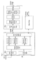
- Fig. 1 shows a schematic diagram of a NodeB comprised of a BBU and an RRU according to an embodiment of the disclosure.
- FIG. 1 The structural schematic diagram of a NodeB comprised of a BBU and an RRU is as shown in Fig. 1 , wherein the RRU comprises but is not limited to an optical fiber interface, a digital intermediate frequency, a transceiver, a power amplifier/low-noise amplifier, a filter and the like.
- the RRU is connected with the BBU through the optical fiber.
- Fig. 2 shows a schematic diagram of an RRU according to an embodiment of the disclosure.
- Fig. 3 shows a stereoscopic schematic diagram of an RRU according to an embodiment of the disclosure (an antenna is not shown).
- the upper side of an antenna 102 is fixed on a common slot 103 to regulate the declination angle of the antenna 102, and the lower end of the antenna 102 is fixed on a holding pole 101 so that the common slot 103 will not bear a much larger force;
- the common slot 103 is installed at the other side of the antenna 102 on the holding pole 101 so that the common slot 103 and the antenna 102 are located at different sides of the holding pole, and such installation way facilitates the installation and disassembly of function modules (1061, 1062, 1063, 1064...) on one hand and makes full use of the surface area of the common slot 103 on the other hand to be inserted more modules; further, the common slot 103 and the antenna 102 are located at different sides, which can balance the gravity of the whole system and lower requirements to the holding pole.
- An optical fiber interface 105 can be installed on the common slot 103, or be installed on each function module (1061, 1062, 1063, 1064%) in accordance with requirements.
- connection method between the common slot 103 and the antenna 102 is that: they can be connected by clinging to each other back to back.
- the antenna 102 has been defined by an operator, it will make it difficult to butt and waterproof the common slot 103 and the antenna 102; however, a small Printed Circuit Board (PCB) can be manufactured with a plug-in thereon corresponding to the antenna 102 to form an interface component, and the interface component is connected with the opening of the combiner of the common slot 103 through flexible cables (e.g. 9 cables), which facilitates the regulation of the declination angle since this is a flexible connection.
- PCB Printed Circuit Board
- Multiple power amplifier cavities can be manufactured in the interior of the function module 1061 having multiple power amplifiers. Since the power amplifiers are arranged up and down, the heat of the upper power amplifiers can be higher than that of the lower power amplifiers; however, since the power amplifiers dissipate heat from both sides, separate cavities can be manufactured in the power amplifiers to avoid air convection up and down.
- the common slot 103 in the RRU of the disclosure comprises but is limited to an optical interface, cavity filters of all frequency bands (all standards), a combiner, a power source, a lightning arrester and the like.
- Each function module is a sub-RRU system, comprising but being limited to a digital system, a transceiver, a power amplifier, a distributed power source and the like.
- the interfaces between the function modules and the common slot 103 can be standardized.
- the antenna 102 is connected with the common slot 103, the common slot 103 is in butt joint with the function modules, and each function module is inserted into the corresponding slot of the common slot 103 according to the corresponding relation between each function module and each slot of the common slot 103.
- the upper side of the antenna 102 is fixed on the common slot 103 through an antenna fixing bracket 1041 to regulate the declination angle of the antenna 102, and the lower end of the antenna102 is fixed on the holding pole 101 through the antenna fixing bracket 1042 so that the common slot 103 will not bear a much large force.
- the common slot 103 is installed at the other side of the antenna 102 on the holding pole 101, which facilitates the installation and disassembly of the function modules on one hand and makes full use of the surface area of the common slot 103 on the other hand to insert more function modules; further, the common slot 103 and the antenna 102 are arranged at different sides, which can balance the gravity of the whole system and lower requirements to the holding pole 101.
- the standard interface direction is defined to decouple all parts, which is a good support to forward compatibility and evolution of successive technologies, for example, if there is an improvement to the common slot 103, it only needs to modify the common slot 103 without any influence to other parts.
- the size of the function modules will be smaller and smaller; however, the function modules are expected to dissipate heat from both sides in view of heat dissipation, and such requirement can be exactly satisfied by the present architecture.
- the function modules are divided from left to right, and can be arranged up and down when distributing the PCB, which is more convenient and reasonable, so that the functional areas of the PCB can be divided clearly and easily and the reliability of the function modules is increased.
- the power amplifiers are arranged in the function modules, that is, the power amplifiers and the function modules are integrated in cavities. Since the power amplifiers and the function modules have little influence to each other, the cost is also small.
- cavity filers are arranged in the common slot 103, that is, the filter cavities applying different frequency bands or different standards are integrated to save space. Since the filter cavities have little influence to each other, the cost is also small.
- some special tools e.g., a flashlight tool and swaging tool etc.
- a flashlight tool and swaging tool etc. can be manufactured on the common slot 103, which is low in cost and can greatly improve work efficiency.
- the RRU of the disclosure is located in the distributed NodeB (a BBU and an RRU) system, during the working process, the RRU performs transmission of the service data and operation commands with the BBU through optical fibers, and performs reception and transmission of radio frequency signals with the antenna through interfaces or cables.
- the common slot can be designed according to requirements with respect to frequency bands, standards, upgrading, evolution and the like. After the interface standard is formulated, each function module can be separately repaired, upgraded and changed, which brings about strong flexibility and can reduce the costs of network construction, repair and upgrading.
- the technical problem to be solved by the disclosure is the architecture of RRUs in a multiband and multi-standard mobile communication system.
- the standard interface of the RRU common slot can be defined to realize independent development of the common slot and the modules of all frequency bands (all standards), which provides a good support for forward compatibility and evolution of successive technologies and is good for cost reduction, design, installation, maintenance and upgrading.
- all aforementioned modules or steps of the disclosure can be realized by a general computing device, and they can be centralized on a single computing device or distributed on a network comprised by multiple computing devices; preferably, they are realized by the executable program codes of the computing device so that they can be stored in a memory device to be executed by the computing device, or they can be manufactured into integrated circuit modules, or they can be realized by manufacturing multiple modules or steps of them into a single integrated circuit module.
- the disclosure is not limited to any specific combination of hardware or software.
Landscapes
- Engineering & Computer Science (AREA)
- Signal Processing (AREA)
- Computer Networks & Wireless Communication (AREA)
- Transceivers (AREA)
- Details Of Aerials (AREA)
- Support Of Aerials (AREA)
- Variable-Direction Aerials And Aerial Arrays (AREA)
Abstract
Description
- The disclosure relates to the field of communications, particularly to a Remote Radio Unit (RRU).
- In a mobile communication system, a distributed NodeB applies the design of an open framework, and the NodeB comprises a Base Band Unit (BBU) and an RRU. The BBU realizes functions such as control management, baseband processing, IUB interface and the like; wherein the IUB interface is an interface between a Radio Network Controller (RNC) and a NodeB, and a large number of macrocell NodeBs are placed in an obtainable central computer room by the BBU in a centralized manner and a baseband part is processed in a centralized way; and the RRU integrates radio frequency-related functions such as an power amplifier, a transceiver, a diplexer and the like. The BBU and the RRU are connected through an optical fiber. Due to relatively-low engineering requirements, flexible installation modes and excellent coverage performance, this new networking solution has attracted more and more operators.
- Regarding a multiband (multi-standard) RRU system, a processing method in related technologies is to place modules supporting different frequency bands (different standards) in the interior of one RRU in a centralized manner or simply divide the RRU into active parts and passive parts.
- In related technologies, an RRU is extended inconveniently while adding frequency bands, and the whole RRU has to be replaced. In the prior art, modules working in different frequency bands (different standards) share one cavity, where there are higher requirements for inter-modulation, stray and isolation. Modules supporting different frequency bands (different standards) are placed in the interior of one RRU in a centralized manner in the prior art, which will result in influence to each other when a module supporting one frequency band (standard) needs to be replaced or repaired because of failure, and the mean time without failures will decrease exponentially.
- Currently, there is no effective solution for the problem that an RRU is extended inconveniently while adding frequency bands and the whole RRU will be greatly affected in most cases when a fault occurs in a module supporting one frequency band in related technologies.
- The disclosure is provided to solve the problem that an RRU is extended inconveniently while adding frequency bands and the whole RRU will be greatly affected in most cases when a fault occurs in a module supporting one frequency band. Therefore, the main purpose of the disclosure is to provide an RRU to solve the aforementioned problem.
- The technical solution of the disclosure is realized by as follows.
- An RRU comprises: a common slot, an antenna and a plurality of function modules, wherein the common slot is connected with the antenna and comprises a plurality of slots, and each function module is inserted in a different slot of the common slot respectively.
- The RRU may further comprise a holding pole; wherein the common slot is fixed on the holding pole, an upper side of the antenna is fixed on the common slot to regulate a declination angle of the antenna, and a lower end of the antenna is fixed on the holding pole.
- Each function module may be corresponding to a different slot of the common slot.
- The common slot and the antenna may be located at different sides of the holding pole.
- The common slot and the antenna may be connected by closely clinging to each other.
- The RRU may further comprise: power amplifier tubes, which is arranged in the function modules.
- The RRU may further comprise: a cavity filter, which is arranged in the common slot.
- Two sides of the power amplifier tubes may be clung to inner cavity walls of the function modules closely.
- Sub-RRUs working in different frequency bands or different standards may be respectively arranged in different function modules.
- A slot opening may be reserved on the common slot.
- Through the disclosure, in which the RRU comprises a common slot, an antenna and a plurality of function modules, wherein the common slot is connected with the antenna and comprises a plurality of slots, and each function module is inserted in a different slot of the common slot respectively, the problem that an RRU is extended inconveniently while adding frequency bands and the whole RRU will be greatly affected in most cases when a fault occurs in a module supporting one frequency band is solved so that each function module can be separately repaired, upgraded and replaced, and the costs of network construction, repair and upgrading can be reduced.
-
-
Fig. 1 shows a schematic diagram of a NodeB comprised of a BBU and an RRU according to an embodiment of the disclosure; -
Fig. 2 shows a schematic diagram of a Remote Radio Unit (RRU) according to an embodiment of the disclosure; and -
Fig. 3 shows a stereoscopic schematic diagram of an RRU according to an embodiment of the disclosure (an antenna is not shown). - In view of the problem that a Remote Radio Unit (RRU) is extended inconveniently while adding frequency bands and the whole RRU will be greatly affected in most cases when a fault occurs in a module supporting one frequency band, an embodiment of the disclosure provides an RRU.
- The RRU of the disclosure comprises: a common slot, an antenna and a plurality of function modules; wherein the common slot is connected with the antenna and comprises a plurality of slots, and each function module is inserted in a different slot of the common slot respectively.
- It should be explained that, embodiments and characteristics thereof in the subject application can be mutually combined in the case of no conflicts. The disclosure will be described based on the embodiments in combination with the drawings hereinafter.
- According to embodiments of the disclosure, an RRU is provided.
- "NodeB" in Time Division-Synchronous Code Division Multiple Access (TD-SCDMA) network architecture of 3GPP protocol refers to the BBU and the RRU mentioned in the disclosure; and the BBU and the RRU mentioned in the disclosure can also serve as the "eNB" in Long-Term Evolution (LTE) network architecture. The position of the RRU in other protocols (e.g., WCDMA, CDMA2000 etc.) can be deduced by analogy.
-
Fig. 1 shows a schematic diagram of a NodeB comprised of a BBU and an RRU according to an embodiment of the disclosure. - The structural schematic diagram of a NodeB comprised of a BBU and an RRU is as shown in
Fig. 1 , wherein the RRU comprises but is not limited to an optical fiber interface, a digital intermediate frequency, a transceiver, a power amplifier/low-noise amplifier, a filter and the like. The RRU is connected with the BBU through the optical fiber. -
Fig. 2 shows a schematic diagram of an RRU according to an embodiment of the disclosure. -
Fig. 3 shows a stereoscopic schematic diagram of an RRU according to an embodiment of the disclosure (an antenna is not shown). - As shown in
Fig. 2 andFig. 3 , the upper side of anantenna 102 is fixed on acommon slot 103 to regulate the declination angle of theantenna 102, and the lower end of theantenna 102 is fixed on aholding pole 101 so that thecommon slot 103 will not bear a much larger force; thecommon slot 103 is installed at the other side of theantenna 102 on theholding pole 101 so that thecommon slot 103 and theantenna 102 are located at different sides of the holding pole, and such installation way facilitates the installation and disassembly of function modules (1061, 1062, 1063, 1064...) on one hand and makes full use of the surface area of thecommon slot 103 on the other hand to be inserted more modules; further, thecommon slot 103 and theantenna 102 are located at different sides, which can balance the gravity of the whole system and lower requirements to the holding pole. Anoptical fiber interface 105 can be installed on thecommon slot 103, or be installed on each function module (1061, 1062, 1063, 1064...) in accordance with requirements. - Another connection method between the
common slot 103 and theantenna 102 is that: they can be connected by clinging to each other back to back. - If the
antenna 102 has been defined by an operator, it will make it difficult to butt and waterproof thecommon slot 103 and theantenna 102; however, a small Printed Circuit Board (PCB) can be manufactured with a plug-in thereon corresponding to theantenna 102 to form an interface component, and the interface component is connected with the opening of the combiner of thecommon slot 103 through flexible cables (e.g. 9 cables), which facilitates the regulation of the declination angle since this is a flexible connection. - Multiple power amplifier cavities (or one cavity) can be manufactured in the interior of the
function module 1061 having multiple power amplifiers. Since the power amplifiers are arranged up and down, the heat of the upper power amplifiers can be higher than that of the lower power amplifiers; however, since the power amplifiers dissipate heat from both sides, separate cavities can be manufactured in the power amplifiers to avoid air convection up and down. - The
common slot 103 in the RRU of the disclosure comprises but is limited to an optical interface, cavity filters of all frequency bands (all standards), a combiner, a power source, a lightning arrester and the like. Each function module is a sub-RRU system, comprising but being limited to a digital system, a transceiver, a power amplifier, a distributed power source and the like. The interfaces between the function modules and thecommon slot 103 can be standardized. Theantenna 102 is connected with thecommon slot 103, thecommon slot 103 is in butt joint with the function modules, and each function module is inserted into the corresponding slot of thecommon slot 103 according to the corresponding relation between each function module and each slot of thecommon slot 103. - Preferably, in the disclosure, the upper side of the
antenna 102 is fixed on thecommon slot 103 through anantenna fixing bracket 1041 to regulate the declination angle of theantenna 102, and the lower end of the antenna102 is fixed on theholding pole 101 through theantenna fixing bracket 1042 so that thecommon slot 103 will not bear a much large force. - Preferably, in the disclosure, the
common slot 103 is installed at the other side of theantenna 102 on theholding pole 101, which facilitates the installation and disassembly of the function modules on one hand and makes full use of the surface area of thecommon slot 103 on the other hand to insert more function modules; further, thecommon slot 103 and theantenna 102 are arranged at different sides, which can balance the gravity of the whole system and lower requirements to theholding pole 101. - Preferably, in the disclosure, the standard interface direction is defined to decouple all parts, which is a good support to forward compatibility and evolution of successive technologies, for example, if there is an improvement to the
common slot 103, it only needs to modify thecommon slot 103 without any influence to other parts. - Preferably, in the disclosure, because of the higher and higher integration level of future function modules, rapidly-increased processing capability of Field Programmable Gate Array (FPGA), intermediate-frequency Analog to Digital Converter (ADC), integration level of Digital to Analog Converter (DAC), integration of the radio frequency devices and new power amplifier technologies, the size of the function modules will be smaller and smaller; however, the function modules are expected to dissipate heat from both sides in view of heat dissipation, and such requirement can be exactly satisfied by the present architecture.
- Preferably, in the disclosure, the function modules are divided from left to right, and can be arranged up and down when distributing the PCB, which is more convenient and reasonable, so that the functional areas of the PCB can be divided clearly and easily and the reliability of the function modules is increased.
- Preferably, in the disclosure, the power amplifiers are arranged in the function modules, that is, the power amplifiers and the function modules are integrated in cavities. Since the power amplifiers and the function modules have little influence to each other, the cost is also small.
- Preferably, in the disclosure, cavity filers are arranged in the
common slot 103, that is, the filter cavities applying different frequency bands or different standards are integrated to save space. Since the filter cavities have little influence to each other, the cost is also small. - Preferably, in the disclosure, some special tools (e.g., a flashlight tool and swaging tool etc.) can be manufactured on the
common slot 103, which is low in cost and can greatly improve work efficiency. - The RRU of the disclosure is located in the distributed NodeB (a BBU and an RRU) system, during the working process, the RRU performs transmission of the service data and operation commands with the BBU through optical fibers, and performs reception and transmission of radio frequency signals with the antenna through interfaces or cables. The common slot can be designed according to requirements with respect to frequency bands, standards, upgrading, evolution and the like. After the interface standard is formulated, each function module can be separately repaired, upgraded and changed, which brings about strong flexibility and can reduce the costs of network construction, repair and upgrading.
- The technical problem to be solved by the disclosure is the architecture of RRUs in a multiband and multi-standard mobile communication system. By means of the disclosure, the standard interface of the RRU common slot can be defined to realize independent development of the common slot and the modules of all frequency bands (all standards), which provides a good support for forward compatibility and evolution of successive technologies and is good for cost reduction, design, installation, maintenance and upgrading.
- It can be seen from the aforementioned description that, the disclosure achieves the following technical effects.
- A. The common slot and all function modules applies the separated type architecture, which enables a slot opening to be reserved on the common slot and facilities extension.
- B. Requirements for the design technology are greatly lowered, for example, a sub-RRU system A working in different frequency bands (different standards) is an independent function module A, a sub-RRU system B is an independent function module B, and different function modules are different independent cavities. If the sub-RRU system A and the sub-RRU system B share one cavity, requirements for inter-modulation, spuriousness and isolation will be higher. Actually, the sub-RRU system A and the sub-RRU system B in the disclosure are located in different cavities, which avoids influence to each other or has little influence to each other, thus bringing about great benefit for technical design.
- C. It's more beneficial to research and development, and all parts are independent to each other through the standard interface, which facilitates independent management of the blocks and accelerates research and development.
- D. It is conveniently and reasonably installed and easily replaced and repaired on site, for example, if function module A has a problem, it only needs to take down the function module A without influencing the work of the function modules B and C. If the function module A and the function module B are integrated, the function module A and the function module B will influence each other and the mean time withouts failures will at least decrease exponentially.
- E. The structures of the function modules more facilitate heat dissipation of the power amplifiers in the modules; besides the lower side of the power amplifier tubes, which can perform heat dissipation through the copper or aluminum substrate, the upper side of the power amplifier tubes can be led onto the shield box of the power amplifier, in addition, the two sides of the power amplifier tubes are close clung to the wall of the inner cavity of the RRU so that the power amplifiers can dissipate heat from two sides.
- Apparently, those skilled in the art should understand that, all aforementioned modules or steps of the disclosure can be realized by a general computing device, and they can be centralized on a single computing device or distributed on a network comprised by multiple computing devices; preferably, they are realized by the executable program codes of the computing device so that they can be stored in a memory device to be executed by the computing device, or they can be manufactured into integrated circuit modules, or they can be realized by manufacturing multiple modules or steps of them into a single integrated circuit module. In such a way, the disclosure is not limited to any specific combination of hardware or software.
- The above are only preferred embodiments of the disclosure and are not limited to the disclosure, and for those skilled in the art, there may be various modifications and changes to the disclosure. Any modification, equivalent replacement and improvement made within the spirit and principle of the disclosure should be included in the protection scope of the disclosure.
Claims (10)
- A Remote Radio Unit (RRU), comprising: a common slot, an antenna and a plurality of function modules; wherein the common slot is connected with the antenna and comprises a plurality of slots, and each function module is inserted in a different slot of the common slot respectively.
- The RRU according to claim 1, further comprising: a holding pole; wherein the common slot is fixed on the holding pole, an upper side of the antenna is fixed on the common slot to regulate a declination angle of the antenna, and a lower end of the antenna is fixed on the holding pole.
- The RRU according to claim 1, wherein each function module is corresponding to a different slot of the common slot.
- The RRU according to claim 2, wherein the common slot and the antenna are located at different sides of the holding pole.
- The RRU according to claim 1, wherein the common slot and the antenna are connected by closely clinging to each other.
- The RRU according to claim 1, further comprising: power amplifier tubes, arranged in the function modules.
- The RRU according to claim 1, further comprising: a cavity filter, arranged in the common slot.
- The RRU according to claim 6, wherein two sides of the power amplifier tubes are clung to inner cavity walls of the function modules closely.
- The RRU according to any one of claims 1 to 8, wherein sub-RRUs working in different frequency bands or different standards are respectively arranged in different function modules.
- The RRU according to any one of claims 1 to 8, wherein a slot opening is reserved on the common slot.
Applications Claiming Priority (2)
| Application Number | Priority Date | Filing Date | Title |
|---|---|---|---|
| CN200910179833.8A CN102044736B (en) | 2009-10-14 | 2009-10-14 | Radio remote unit |
| PCT/CN2010/073528 WO2010145461A1 (en) | 2009-10-14 | 2010-06-03 | Remote radio unit |
Publications (3)
| Publication Number | Publication Date |
|---|---|
| EP2469718A1 true EP2469718A1 (en) | 2012-06-27 |
| EP2469718A4 EP2469718A4 (en) | 2015-04-15 |
| EP2469718B1 EP2469718B1 (en) | 2018-10-31 |
Family
ID=43355830
Family Applications (1)
| Application Number | Title | Priority Date | Filing Date |
|---|---|---|---|
| EP10788857.0A Not-in-force EP2469718B1 (en) | 2009-10-14 | 2010-06-03 | Remote radio unit |
Country Status (6)
| Country | Link |
|---|---|
| US (1) | US8797229B2 (en) |
| EP (1) | EP2469718B1 (en) |
| JP (1) | JP5493001B2 (en) |
| KR (1) | KR101407793B1 (en) |
| CN (1) | CN102044736B (en) |
| WO (1) | WO2010145461A1 (en) |
Cited By (1)
| Publication number | Priority date | Publication date | Assignee | Title |
|---|---|---|---|---|
| WO2019160951A1 (en) | 2018-02-16 | 2019-08-22 | Commscope Technologies Llc | Variable upgradable multi-user port of a remote antenna unit |
Families Citing this family (24)
| Publication number | Priority date | Publication date | Assignee | Title |
|---|---|---|---|---|
| JP5236661B2 (en) | 2006-12-26 | 2013-07-17 | ダリ システムズ カンパニー リミテッド | Method and system for linearizing baseband predistortion in multi-channel wideband communication system |
| KR20180026793A (en) | 2010-08-17 | 2018-03-13 | 달리 시스템즈 씨오. 엘티디. | Neutral host architecture for a distributed antenna system |
| CN103597807B (en) | 2010-09-14 | 2015-09-30 | 大理系统有限公司 | Remotely reconfigurable distributed antenna system and method |
| CN102647739B (en) * | 2011-02-18 | 2014-08-06 | 鼎桥通信技术有限公司 | Radio remote unit |
| US9414437B2 (en) | 2011-03-28 | 2016-08-09 | Telefonaktiebolaget L M Ericsson (Publ) | Radio device and method for manufacturing the radio device |
| WO2012159358A1 (en) | 2011-08-01 | 2012-11-29 | 华为技术有限公司 | Lightning protection radio remote unit, distributed base station and lightning protection system and method thereof |
| US11564110B2 (en) * | 2011-11-07 | 2023-01-24 | Dali Wireless, Inc. | Soft hand-off and routing data in a virtualized distributed antenna system |
| CN102522634B (en) * | 2011-12-13 | 2015-04-15 | 华为技术有限公司 | Antenna apparatus, base station and communication system |
| CN102714345B (en) * | 2012-03-09 | 2014-11-05 | 华为技术有限公司 | Antenna system, base station and communication system |
| CN102709710B (en) * | 2012-05-18 | 2014-11-19 | 京信通信系统(中国)有限公司 | Active covering unit and active covering array composed of it |
| DE102012011892A1 (en) | 2012-06-15 | 2013-12-19 | Kathrein-Werke Kg | Mounting system for a mobile antenna and a mobile component |
| CN102882583B (en) * | 2012-09-27 | 2015-08-05 | 华为技术有限公司 | A kind of repeater |
| CN103023696B (en) * | 2012-11-28 | 2016-08-03 | 大唐移动通信设备有限公司 | Fault handling method, RRU and fault processing system |
| CN103718379B (en) * | 2013-03-27 | 2017-04-12 | 华为技术有限公司 | Multi-frequency active antenna |
| US20170250927A1 (en) | 2013-12-23 | 2017-08-31 | Dali Systems Co. Ltd. | Virtual radio access network using software-defined network of remotes and digital multiplexing switches |
| KR102140293B1 (en) * | 2014-02-24 | 2020-08-11 | 주식회사 케이엠더블유 | Multi band antenna device |
| CN105519233A (en) * | 2014-07-17 | 2016-04-20 | 华为技术有限公司 | A distributed base station |
| CN105357777B (en) * | 2014-08-19 | 2019-05-28 | 华为技术有限公司 | Communication products and base station systems |
| BR112017022657A2 (en) * | 2015-04-20 | 2018-07-17 | Thomson Licensing | antenna mounting on an electronic device |
| CN105589154B (en) * | 2016-03-09 | 2018-10-19 | 江苏俊知传感技术有限公司 | A kind of dragging optical cable component production equipment thread-laying device and its hanging wire method |
| WO2018111480A2 (en) * | 2016-12-16 | 2018-06-21 | Commscope Technologies Llc | Integrated cell site sector module |
| CN108471319B (en) * | 2017-02-21 | 2020-05-22 | 中兴通讯股份有限公司 | Base station, radio remote unit and mainboard thereof, radio sub-card and channel self-building method |
| WO2021034875A1 (en) * | 2019-08-21 | 2021-02-25 | Commscope Technologies Llc | Jumper cable assembly |
| CN116647249B (en) * | 2023-07-27 | 2023-10-20 | 上海瀚儒通信技术有限公司 | Modularized intelligent signal shielding device unit, shielding device and shielding control method |
Family Cites Families (18)
| Publication number | Priority date | Publication date | Assignee | Title |
|---|---|---|---|---|
| GB2272133B (en) * | 1992-11-02 | 1996-06-12 | Motorola Inc | Radio system |
| CA2154318A1 (en) * | 1994-08-25 | 1996-02-26 | Richard David Poole | Adaptable radio telephone handset |
| US6188373B1 (en) * | 1996-07-16 | 2001-02-13 | Metawave Communications Corporation | System and method for per beam elevation scanning |
| US7603139B1 (en) * | 1999-03-25 | 2009-10-13 | Kantan Inc. | Methods and apparatus for a flexible wireless communication and cellular telephone system |
| US6268828B1 (en) * | 2000-01-11 | 2001-07-31 | Metawave Communications Corporation | Cylindrical antenna coherent feed system and method |
| US6421021B1 (en) * | 2001-04-17 | 2002-07-16 | Raytheon Company | Active array lens antenna using CTS space feed for reduced antenna depth |
| CN1199398C (en) * | 2002-04-16 | 2005-04-27 | 智邦科技股份有限公司 | Access devices with different wireless network standards |
| JP3694683B2 (en) * | 2002-09-17 | 2005-09-14 | 陽慶電子股▲ふん▼有限公司 | Multi-module wireless LAN maintenance device |
| JP3697442B2 (en) * | 2002-11-14 | 2005-09-21 | 三菱電機株式会社 | Phased array antenna device |
| US6999042B2 (en) * | 2003-03-03 | 2006-02-14 | Andrew Corporation | Low visual impact monopole tower for wireless communications |
| US6982680B2 (en) * | 2003-07-08 | 2006-01-03 | Ems Technologies, Inc. | Antenna tower and support structure therefor |
| EP1825568A1 (en) * | 2004-12-13 | 2007-08-29 | TELEFONAKTIEBOLAGET LM ERICSSON (publ) | An antenna arrangement and a method relating thereto |
| CN201001113Y (en) * | 2006-12-21 | 2008-01-02 | 华为技术有限公司 | A connector and a radio frequency device integrated with the connector |
| CN101452349B (en) * | 2007-11-30 | 2012-05-09 | 原相科技股份有限公司 | Cursor control device, method and image system on image display device |
| CN201238071Y (en) * | 2008-07-10 | 2009-05-13 | 中国移动通信集团公司 | Plug connector and plug connection member used for antenna subsystem |
| CN201247823Y (en) * | 2008-07-22 | 2009-05-27 | 鼎桥通信技术有限公司 | Antenna subsystem, antenna unit and radio frequency zooming unit |
| CN201238386Y (en) | 2008-07-30 | 2009-05-13 | 京信通信系统(中国)有限公司 | Multi-frequency band digital radio frequency zooming system |
| CN201467115U (en) | 2009-07-08 | 2010-05-12 | 鼎桥通信技术有限公司 | An Antenna Subsystem |
-
2009
- 2009-10-14 CN CN200910179833.8A patent/CN102044736B/en not_active Expired - Fee Related
-
2010
- 2010-06-03 US US13/258,132 patent/US8797229B2/en not_active Expired - Fee Related
- 2010-06-03 EP EP10788857.0A patent/EP2469718B1/en not_active Not-in-force
- 2010-06-03 JP JP2012533462A patent/JP5493001B2/en not_active Expired - Fee Related
- 2010-06-03 KR KR1020127012088A patent/KR101407793B1/en not_active Expired - Fee Related
- 2010-06-03 WO PCT/CN2010/073528 patent/WO2010145461A1/en not_active Ceased
Cited By (2)
| Publication number | Priority date | Publication date | Assignee | Title |
|---|---|---|---|---|
| WO2019160951A1 (en) | 2018-02-16 | 2019-08-22 | Commscope Technologies Llc | Variable upgradable multi-user port of a remote antenna unit |
| EP3752925A4 (en) * | 2018-02-16 | 2021-12-01 | CommScope Technologies LLC | Variable upgradable multi-user port of a remote antenna unit |
Also Published As
| Publication number | Publication date |
|---|---|
| EP2469718B1 (en) | 2018-10-31 |
| CN102044736B (en) | 2015-05-20 |
| JP2013507854A (en) | 2013-03-04 |
| WO2010145461A1 (en) | 2010-12-23 |
| US8797229B2 (en) | 2014-08-05 |
| CN102044736A (en) | 2011-05-04 |
| KR101407793B1 (en) | 2014-07-02 |
| EP2469718A4 (en) | 2015-04-15 |
| US20120206885A1 (en) | 2012-08-16 |
| KR20120081208A (en) | 2012-07-18 |
| JP5493001B2 (en) | 2014-05-14 |
Similar Documents
| Publication | Publication Date | Title |
|---|---|---|
| US8797229B2 (en) | Remote radio unit | |
| EP2592863B1 (en) | Distributed load balancing in a radio access network | |
| US8346092B2 (en) | Antenna device | |
| EP3348115B1 (en) | Antenna-integrated radio with wireless fronthaul | |
| KR101586295B1 (en) | Antenna apparatus, base station, and communication system | |
| CN101466168B (en) | Wireless device controller, wireless communication system, and communication data transmission method | |
| WO2017031959A1 (en) | Radio remote unit setting method and radio remote unit | |
| CN108235451A (en) | A kind of portable private network base station system of integration | |
| CN102740508A (en) | Active covering array | |
| HK1166890A (en) | Remote radio unit | |
| EP2696650B1 (en) | Base station | |
| CN101035323A (en) | Micro-wave extension method and device of the time division duplex mobile communication system | |
| CN107547123A (en) | A kind of Remote Radio Unit and extensive multiple-input and multiple-output Remote Radio Unit | |
| CN102709710B (en) | Active covering unit and active covering array composed of it | |
| CN217363064U (en) | 5G room divides double-circuit system of shifting frequency | |
| CN111869316A (en) | Heterogeneous mobile radio equipment providing mobile radio services for at least one mobile radio cell | |
| CN202696601U (en) | Active cover unit and active cover array composed of the same | |
| KR102155140B1 (en) | Communication node and operating method of the communication node, and distributed antenna system including the same | |
| CN102215059A (en) | Common mode supporting data transmission method and system between BBU (Building Base band Unit) and RRU (Radio Remote Unit) | |
| CN218959131U (en) | Network Architecture and Base Station | |
| CN106941357B (en) | Networking method and system based on software-defined radio | |
| KR102155136B1 (en) | Communication node, and operating method of the same | |
| CN202696916U (en) | Active covering array | |
| CN106793180A (en) | Base station | |
| EP1850535A1 (en) | Software configurable and definable base station |
Legal Events
| Date | Code | Title | Description |
|---|---|---|---|
| PUAI | Public reference made under article 153(3) epc to a published international application that has entered the european phase |
Free format text: ORIGINAL CODE: 0009012 |
|
| 17P | Request for examination filed |
Effective date: 20120320 |
|
| AK | Designated contracting states |
Kind code of ref document: A1 Designated state(s): AL AT BE BG CH CY CZ DE DK EE ES FI FR GB GR HR HU IE IS IT LI LT LU LV MC MK MT NL NO PL PT RO SE SI SK SM TR |
|
| REG | Reference to a national code |
Ref country code: HK Ref legal event code: DE Ref document number: 1166890 Country of ref document: HK |
|
| DAX | Request for extension of the european patent (deleted) | ||
| RA4 | Supplementary search report drawn up and despatched (corrected) |
Effective date: 20150318 |
|
| RIC1 | Information provided on ipc code assigned before grant |
Ipc: H04M 1/725 20060101ALI20150312BHEP Ipc: H04B 1/38 20150101AFI20150312BHEP Ipc: H04M 1/02 20060101ALI20150312BHEP Ipc: H04W 8/18 20090101ALI20150312BHEP |
|
| GRAP | Despatch of communication of intention to grant a patent |
Free format text: ORIGINAL CODE: EPIDOSNIGR1 |
|
| STAA | Information on the status of an ep patent application or granted ep patent |
Free format text: STATUS: GRANT OF PATENT IS INTENDED |
|
| INTG | Intention to grant announced |
Effective date: 20180515 |
|
| GRAS | Grant fee paid |
Free format text: ORIGINAL CODE: EPIDOSNIGR3 |
|
| GRAA | (expected) grant |
Free format text: ORIGINAL CODE: 0009210 |
|
| STAA | Information on the status of an ep patent application or granted ep patent |
Free format text: STATUS: THE PATENT HAS BEEN GRANTED |
|
| AK | Designated contracting states |
Kind code of ref document: B1 Designated state(s): AL AT BE BG CH CY CZ DE DK EE ES FI FR GB GR HR HU IE IS IT LI LT LU LV MC MK MT NL NO PL PT RO SE SI SK SM TR |
|
| REG | Reference to a national code |
Ref country code: CH Ref legal event code: EP Ref country code: GB Ref legal event code: FG4D |
|
| REG | Reference to a national code |
Ref country code: AT Ref legal event code: REF Ref document number: 1060630 Country of ref document: AT Kind code of ref document: T Effective date: 20181115 |
|
| REG | Reference to a national code |
Ref country code: DE Ref legal event code: R096 Ref document number: 602010054805 Country of ref document: DE |
|
| REG | Reference to a national code |
Ref country code: IE Ref legal event code: FG4D |
|
| REG | Reference to a national code |
Ref country code: HK Ref legal event code: WD Ref document number: 1166890 Country of ref document: HK |
|
| REG | Reference to a national code |
Ref country code: NL Ref legal event code: MP Effective date: 20181031 |
|
| REG | Reference to a national code |
Ref country code: LT Ref legal event code: MG4D |
|
| REG | Reference to a national code |
Ref country code: AT Ref legal event code: MK05 Ref document number: 1060630 Country of ref document: AT Kind code of ref document: T Effective date: 20181031 |
|
| PG25 | Lapsed in a contracting state [announced via postgrant information from national office to epo] |
Ref country code: LT Free format text: LAPSE BECAUSE OF FAILURE TO SUBMIT A TRANSLATION OF THE DESCRIPTION OR TO PAY THE FEE WITHIN THE PRESCRIBED TIME-LIMIT Effective date: 20181031 Ref country code: HR Free format text: LAPSE BECAUSE OF FAILURE TO SUBMIT A TRANSLATION OF THE DESCRIPTION OR TO PAY THE FEE WITHIN THE PRESCRIBED TIME-LIMIT Effective date: 20181031 Ref country code: PL Free format text: LAPSE BECAUSE OF FAILURE TO SUBMIT A TRANSLATION OF THE DESCRIPTION OR TO PAY THE FEE WITHIN THE PRESCRIBED TIME-LIMIT Effective date: 20181031 Ref country code: BG Free format text: LAPSE BECAUSE OF FAILURE TO SUBMIT A TRANSLATION OF THE DESCRIPTION OR TO PAY THE FEE WITHIN THE PRESCRIBED TIME-LIMIT Effective date: 20190131 Ref country code: AT Free format text: LAPSE BECAUSE OF FAILURE TO SUBMIT A TRANSLATION OF THE DESCRIPTION OR TO PAY THE FEE WITHIN THE PRESCRIBED TIME-LIMIT Effective date: 20181031 Ref country code: NO Free format text: LAPSE BECAUSE OF FAILURE TO SUBMIT A TRANSLATION OF THE DESCRIPTION OR TO PAY THE FEE WITHIN THE PRESCRIBED TIME-LIMIT Effective date: 20190131 Ref country code: ES Free format text: LAPSE BECAUSE OF FAILURE TO SUBMIT A TRANSLATION OF THE DESCRIPTION OR TO PAY THE FEE WITHIN THE PRESCRIBED TIME-LIMIT Effective date: 20181031 Ref country code: IS Free format text: LAPSE BECAUSE OF FAILURE TO SUBMIT A TRANSLATION OF THE DESCRIPTION OR TO PAY THE FEE WITHIN THE PRESCRIBED TIME-LIMIT Effective date: 20190228 Ref country code: LV Free format text: LAPSE BECAUSE OF FAILURE TO SUBMIT A TRANSLATION OF THE DESCRIPTION OR TO PAY THE FEE WITHIN THE PRESCRIBED TIME-LIMIT Effective date: 20181031 Ref country code: FI Free format text: LAPSE BECAUSE OF FAILURE TO SUBMIT A TRANSLATION OF THE DESCRIPTION OR TO PAY THE FEE WITHIN THE PRESCRIBED TIME-LIMIT Effective date: 20181031 |
|
| PG25 | Lapsed in a contracting state [announced via postgrant information from national office to epo] |
Ref country code: GR Free format text: LAPSE BECAUSE OF FAILURE TO SUBMIT A TRANSLATION OF THE DESCRIPTION OR TO PAY THE FEE WITHIN THE PRESCRIBED TIME-LIMIT Effective date: 20190201 Ref country code: AL Free format text: LAPSE BECAUSE OF FAILURE TO SUBMIT A TRANSLATION OF THE DESCRIPTION OR TO PAY THE FEE WITHIN THE PRESCRIBED TIME-LIMIT Effective date: 20181031 Ref country code: SE Free format text: LAPSE BECAUSE OF FAILURE TO SUBMIT A TRANSLATION OF THE DESCRIPTION OR TO PAY THE FEE WITHIN THE PRESCRIBED TIME-LIMIT Effective date: 20181031 Ref country code: NL Free format text: LAPSE BECAUSE OF FAILURE TO SUBMIT A TRANSLATION OF THE DESCRIPTION OR TO PAY THE FEE WITHIN THE PRESCRIBED TIME-LIMIT Effective date: 20181031 Ref country code: PT Free format text: LAPSE BECAUSE OF FAILURE TO SUBMIT A TRANSLATION OF THE DESCRIPTION OR TO PAY THE FEE WITHIN THE PRESCRIBED TIME-LIMIT Effective date: 20190301 |
|
| PG25 | Lapsed in a contracting state [announced via postgrant information from national office to epo] |
Ref country code: DK Free format text: LAPSE BECAUSE OF FAILURE TO SUBMIT A TRANSLATION OF THE DESCRIPTION OR TO PAY THE FEE WITHIN THE PRESCRIBED TIME-LIMIT Effective date: 20181031 Ref country code: CZ Free format text: LAPSE BECAUSE OF FAILURE TO SUBMIT A TRANSLATION OF THE DESCRIPTION OR TO PAY THE FEE WITHIN THE PRESCRIBED TIME-LIMIT Effective date: 20181031 |
|
| PGFP | Annual fee paid to national office [announced via postgrant information from national office to epo] |
Ref country code: IT Payment date: 20190619 Year of fee payment: 10 |
|
| REG | Reference to a national code |
Ref country code: DE Ref legal event code: R097 Ref document number: 602010054805 Country of ref document: DE |
|
| PG25 | Lapsed in a contracting state [announced via postgrant information from national office to epo] |
Ref country code: RO Free format text: LAPSE BECAUSE OF FAILURE TO SUBMIT A TRANSLATION OF THE DESCRIPTION OR TO PAY THE FEE WITHIN THE PRESCRIBED TIME-LIMIT Effective date: 20181031 Ref country code: SM Free format text: LAPSE BECAUSE OF FAILURE TO SUBMIT A TRANSLATION OF THE DESCRIPTION OR TO PAY THE FEE WITHIN THE PRESCRIBED TIME-LIMIT Effective date: 20181031 Ref country code: EE Free format text: LAPSE BECAUSE OF FAILURE TO SUBMIT A TRANSLATION OF THE DESCRIPTION OR TO PAY THE FEE WITHIN THE PRESCRIBED TIME-LIMIT Effective date: 20181031 Ref country code: SK Free format text: LAPSE BECAUSE OF FAILURE TO SUBMIT A TRANSLATION OF THE DESCRIPTION OR TO PAY THE FEE WITHIN THE PRESCRIBED TIME-LIMIT Effective date: 20181031 |
|
| PLBE | No opposition filed within time limit |
Free format text: ORIGINAL CODE: 0009261 |
|
| STAA | Information on the status of an ep patent application or granted ep patent |
Free format text: STATUS: NO OPPOSITION FILED WITHIN TIME LIMIT |
|
| 26N | No opposition filed |
Effective date: 20190801 |
|
| PG25 | Lapsed in a contracting state [announced via postgrant information from national office to epo] |
Ref country code: SI Free format text: LAPSE BECAUSE OF FAILURE TO SUBMIT A TRANSLATION OF THE DESCRIPTION OR TO PAY THE FEE WITHIN THE PRESCRIBED TIME-LIMIT Effective date: 20181031 |
|
| PGFP | Annual fee paid to national office [announced via postgrant information from national office to epo] |
Ref country code: DE Payment date: 20190628 Year of fee payment: 10 |
|
| PG25 | Lapsed in a contracting state [announced via postgrant information from national office to epo] |
Ref country code: MC Free format text: LAPSE BECAUSE OF FAILURE TO SUBMIT A TRANSLATION OF THE DESCRIPTION OR TO PAY THE FEE WITHIN THE PRESCRIBED TIME-LIMIT Effective date: 20181031 |
|
| REG | Reference to a national code |
Ref country code: CH Ref legal event code: PL |
|
| GBPC | Gb: european patent ceased through non-payment of renewal fee |
Effective date: 20190603 |
|
| REG | Reference to a national code |
Ref country code: BE Ref legal event code: MM Effective date: 20190630 |
|
| PG25 | Lapsed in a contracting state [announced via postgrant information from national office to epo] |
Ref country code: TR Free format text: LAPSE BECAUSE OF FAILURE TO SUBMIT A TRANSLATION OF THE DESCRIPTION OR TO PAY THE FEE WITHIN THE PRESCRIBED TIME-LIMIT Effective date: 20181031 |
|
| PG25 | Lapsed in a contracting state [announced via postgrant information from national office to epo] |
Ref country code: GB Free format text: LAPSE BECAUSE OF NON-PAYMENT OF DUE FEES Effective date: 20190603 Ref country code: IE Free format text: LAPSE BECAUSE OF NON-PAYMENT OF DUE FEES Effective date: 20190603 |
|
| PG25 | Lapsed in a contracting state [announced via postgrant information from national office to epo] |
Ref country code: LU Free format text: LAPSE BECAUSE OF NON-PAYMENT OF DUE FEES Effective date: 20190603 Ref country code: CH Free format text: LAPSE BECAUSE OF NON-PAYMENT OF DUE FEES Effective date: 20190630 Ref country code: LI Free format text: LAPSE BECAUSE OF NON-PAYMENT OF DUE FEES Effective date: 20190630 Ref country code: BE Free format text: LAPSE BECAUSE OF NON-PAYMENT OF DUE FEES Effective date: 20190630 |
|
| PG25 | Lapsed in a contracting state [announced via postgrant information from national office to epo] |
Ref country code: FR Free format text: LAPSE BECAUSE OF NON-PAYMENT OF DUE FEES Effective date: 20190630 |
|
| REG | Reference to a national code |
Ref country code: DE Ref legal event code: R119 Ref document number: 602010054805 Country of ref document: DE |
|
| PG25 | Lapsed in a contracting state [announced via postgrant information from national office to epo] |
Ref country code: CY Free format text: LAPSE BECAUSE OF FAILURE TO SUBMIT A TRANSLATION OF THE DESCRIPTION OR TO PAY THE FEE WITHIN THE PRESCRIBED TIME-LIMIT Effective date: 20181031 Ref country code: DE Free format text: LAPSE BECAUSE OF NON-PAYMENT OF DUE FEES Effective date: 20210101 |
|
| PG25 | Lapsed in a contracting state [announced via postgrant information from national office to epo] |
Ref country code: MT Free format text: LAPSE BECAUSE OF FAILURE TO SUBMIT A TRANSLATION OF THE DESCRIPTION OR TO PAY THE FEE WITHIN THE PRESCRIBED TIME-LIMIT Effective date: 20181031 Ref country code: HU Free format text: LAPSE BECAUSE OF FAILURE TO SUBMIT A TRANSLATION OF THE DESCRIPTION OR TO PAY THE FEE WITHIN THE PRESCRIBED TIME-LIMIT; INVALID AB INITIO Effective date: 20100603 |
|
| PG25 | Lapsed in a contracting state [announced via postgrant information from national office to epo] |
Ref country code: IT Free format text: LAPSE BECAUSE OF NON-PAYMENT OF DUE FEES Effective date: 20200603 |
|
| PG25 | Lapsed in a contracting state [announced via postgrant information from national office to epo] |
Ref country code: MK Free format text: LAPSE BECAUSE OF FAILURE TO SUBMIT A TRANSLATION OF THE DESCRIPTION OR TO PAY THE FEE WITHIN THE PRESCRIBED TIME-LIMIT Effective date: 20181031 |