EP2469683A1 - Battery heating circuit - Google Patents
Battery heating circuit Download PDFInfo
- Publication number
- EP2469683A1 EP2469683A1 EP20110166872 EP11166872A EP2469683A1 EP 2469683 A1 EP2469683 A1 EP 2469683A1 EP 20110166872 EP20110166872 EP 20110166872 EP 11166872 A EP11166872 A EP 11166872A EP 2469683 A1 EP2469683 A1 EP 2469683A1
- Authority
- EP
- European Patent Office
- Prior art keywords
- battery
- switch unit
- switch
- heating circuit
- transformer
- Prior art date
- Legal status (The legal status is an assumption and is not a legal conclusion. Google has not performed a legal analysis and makes no representation as to the accuracy of the status listed.)
- Withdrawn
Links
Images


Classifications
-
- H—ELECTRICITY
- H01—ELECTRIC ELEMENTS
- H01M—PROCESSES OR MEANS, e.g. BATTERIES, FOR THE DIRECT CONVERSION OF CHEMICAL ENERGY INTO ELECTRICAL ENERGY
- H01M10/00—Secondary cells; Manufacture thereof
- H01M10/42—Methods or arrangements for servicing or maintenance of secondary cells or secondary half-cells
- H01M10/425—Structural combination with electronic components, e.g. electronic circuits integrated to the outside of the casing
-
- H—ELECTRICITY
- H02—GENERATION; CONVERSION OR DISTRIBUTION OF ELECTRIC POWER
- H02J—ELECTRIC POWER NETWORKS; CIRCUIT ARRANGEMENTS OR SYSTEMS FOR SUPPLYING OR DISTRIBUTING ELECTRIC POWER; SYSTEMS FOR STORING ELECTRIC ENERGY
- H02J7/00—Circuit arrangements for charging or discharging batteries or for supplying loads from batteries
- H02J7/875—Charging or discharging for charge maintenance, battery initiation or rejuvenation
-
- H—ELECTRICITY
- H01—ELECTRIC ELEMENTS
- H01M—PROCESSES OR MEANS, e.g. BATTERIES, FOR THE DIRECT CONVERSION OF CHEMICAL ENERGY INTO ELECTRICAL ENERGY
- H01M10/00—Secondary cells; Manufacture thereof
- H01M10/42—Methods or arrangements for servicing or maintenance of secondary cells or secondary half-cells
- H01M10/44—Methods for charging or discharging
- H01M10/443—Methods for charging or discharging in response to temperature
-
- H—ELECTRICITY
- H01—ELECTRIC ELEMENTS
- H01M—PROCESSES OR MEANS, e.g. BATTERIES, FOR THE DIRECT CONVERSION OF CHEMICAL ENERGY INTO ELECTRICAL ENERGY
- H01M10/00—Secondary cells; Manufacture thereof
- H01M10/60—Heating or cooling; Temperature control
- H01M10/61—Types of temperature control
- H01M10/615—Heating or keeping warm
-
- H—ELECTRICITY
- H01—ELECTRIC ELEMENTS
- H01M—PROCESSES OR MEANS, e.g. BATTERIES, FOR THE DIRECT CONVERSION OF CHEMICAL ENERGY INTO ELECTRICAL ENERGY
- H01M10/00—Secondary cells; Manufacture thereof
- H01M10/60—Heating or cooling; Temperature control
- H01M10/65—Means for temperature control structurally associated with the cells
- H01M10/657—Means for temperature control structurally associated with the cells by electric or electromagnetic means
- H01M10/6571—Resistive heaters
-
- H—ELECTRICITY
- H01—ELECTRIC ELEMENTS
- H01M—PROCESSES OR MEANS, e.g. BATTERIES, FOR THE DIRECT CONVERSION OF CHEMICAL ENERGY INTO ELECTRICAL ENERGY
- H01M10/00—Secondary cells; Manufacture thereof
- H01M10/42—Methods or arrangements for servicing or maintenance of secondary cells or secondary half-cells
- H01M10/425—Structural combination with electronic components, e.g. electronic circuits integrated to the outside of the casing
- H01M2010/4271—Battery management systems including electronic circuits, e.g. control of current or voltage to keep battery in healthy state, cell balancing
-
- Y—GENERAL TAGGING OF NEW TECHNOLOGICAL DEVELOPMENTS; GENERAL TAGGING OF CROSS-SECTIONAL TECHNOLOGIES SPANNING OVER SEVERAL SECTIONS OF THE IPC; TECHNICAL SUBJECTS COVERED BY FORMER USPC CROSS-REFERENCE ART COLLECTIONS [XRACs] AND DIGESTS
- Y02—TECHNOLOGIES OR APPLICATIONS FOR MITIGATION OR ADAPTATION AGAINST CLIMATE CHANGE
- Y02E—REDUCTION OF GREENHOUSE GAS [GHG] EMISSIONS, RELATED TO ENERGY GENERATION, TRANSMISSION OR DISTRIBUTION
- Y02E60/00—Enabling technologies; Technologies with a potential or indirect contribution to GHG emissions mitigation
- Y02E60/10—Energy storage using batteries
Definitions
- the present invention pertains to electric and electronic field, in particular to a battery heating circuit.
- the battery which serves as the power supply unit for electric motor cars or electronic devices, must be adaptive to these complex conditions.
- the service life and charging/discharging cycle performance of battery must be considered; especially, when electric motor cars or electronic devices are used in low temperature environments, the battery must have outstanding low temperature charging/discharging performance and higher input/output power.
- the present invention provides a battery heating circuit.
- the object of the present invention is to provide a battery heating circuit, in order to solve the problem of decreased capacity of battery caused by increased resistance and polarization of battery under low temperature conditions.
- the battery heating circuit comprises a switch unit, a switching control module, a one-way semiconductor element, a damping element and a transformer, wherein the switching control module is electrically connected with the switch unit; the battery, damping element, first winding of the transformer, and switch unit are connected in series with each other to constitute a battery discharging circuit; the battery, damping element, second winding of the transformer, and one-way semiconductor element are connected in series with each other to constitute a battery charging circuit.
- the switch unit can be controlled by the switching control module to switch on, and then can be controlled to switch off when the current in the battery discharging circuit reaches to a preset value; after that, the transformer transfers the stored energy back to the battery. In that process, the damping element generates heat as the current flows through it, and thereby heats up the battery.
- the transformer takes a current limiting role; in addition, the preset value can be set according to the properties of the battery; therefore, the magnitude of current in the battery charging/discharging circuit is controllable, and damages to the battery caused by over-current can be avoided. In addition, since the magnitude of current is controllable, the switch unit is protected against burnt due to generation of vast heat.
- the transformer in the present invention serves as an energy storage element, and has current limiting function. It can transfer the energy stored in it back to the battery through the battery charging circuit, and thereby can reduce the energy loss in the heating process.
- switching control module refers to any controller that can output control commands (e.g., pulse waveform) under preset conditions or at preset times and thereby controls the switch unit connected to it to switch on or switch off accordingly, for example, the switching control module can be a PLC;
- switch refers to a switch that achieve ON/OFF control by means of electrical signals or achieve ON/OFF control on the basis of the characteristics of the element or component, which is to say, the switch can be an one-way switch (e.g., a switch composed of a two-way switch and a diode connected in series, which can switch on in one direction) or a two-way switch (e.g., a Metal Oxide Semiconductor Field Effect Transistor (MOSFET) or an IGBT with an anti-parallel freewheeling diode); where mentioned in the following text, the term “two-way switch” refers to a switch
- the "battery” refers to an ideal battery that doesn't have internal parasitic resistance and inductance or has very low internal parasitic resistance and inductance, or refers to a battery pack that has internal parasitic resistance and inductance; therefore, those skilled in the art should appreciate: if the battery is an ideal battery that doesn't have internal parasitic resistance and inductance or has very low internal parasitic resistance and inductance, the damping element R refers to an damping element external to the battery; if the battery is a battery pack that has internal parasitic resistance and inductance, the damping element R refers to a damping element external to the battery, or refers to the parasitic resistance in the battery pack.
- the battery can be heated under low temperature condition, which is to say, when the heating condition is met, the heating circuit is controlled to start heating for the battery; when the heating stop condition is met, the heating circuit is controlled to stop heating.
- the battery heating condition and heating stop condition can be set according to the actual ambient conditions, to ensure normal charging/discharging performance of the battery.
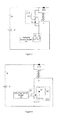
- FIG. 1 is a circuit diagram of the heating circuit provided in the present invention.
- the present invention provides a battery heating circuit, comprising a switch unit 10, a switching control module 100, a one-way semiconductor element D10, a damping element R and a transformer T, wherein, the switching control module 100 is electrically connected with the switch unit 10; the battery E, damping element R, first winding of the transformer T, and switch unit 10 are connected in series with each other to constitute a battery discharging circuit; and the battery E, damping element R, second winding of the transformer T, and one-way semiconductor element D10 are connected in series with each other to constitute a battery charging circuit.
- the switching control module 100 can control the switch unit 10 to switch off when the current flowing through the battery E reaches to a preset value in the positive half cycle, and can control the switch unit 10 to switch on when the current flowing through the battery E reaches to zero in the negative half cycle.
- the damping element R By keeping the current flowing through the damping element R continuously, the damping element R generates heat, and thereby heats up the battery E.
- FIG. 2 is a timing sequence diagram of waveform of the heating circuit provided in the present invention.
- the switching control module 100 controls the switch unit 10 to switch on; now, the positive electrode of the battery E is connected with the negative electrode of the battery E and forms a closed circuit; thus, the current I main in the battery E rises up slowly due to the existence of the inductance in transformer T (see the time period t1), and some energy is stored in the transformer T.
- the switching control module 100 controls the switch unit 10 to switch off; now, the transformer T transfers the energy stored in it back to the battery through the one-way semiconductor element D10, as indicated by the time period t2. After that, when the current in the battery E is zero, the switching control module 100 controls the switch unit 10 to switch on again, and thus another cycle starts. The cycles continue on and on, till the battery E is heated up satisfactorily.
- the current I main in the battery E is limited; alternatively, the magnitude of the current I main in the battery E can be controlled by controlling the switch-off time of the switch unit 10 with the switching control module 100. Moreover, the magnitude of the charging/discharging current of the battery E can be controlled by changing the ratio of winding between the first winding (i.e., primary coil) and the second winding (i.e., secondary coil) of the transformer T. The higher the ratio of winding between the first winding and the second winding is, the smaller the current charged back from the second wiring to the battery E will be.
- the first winding i.e., primary coil
- the second winding i.e., secondary coil
- the heating circuit can further comprises a first voltage absorption circuit 210, which is connected in parallel between the ends of the first winding of the transformer T, and the first voltage absorption circuit 210 is configured to consume the voltage induced in the first winding when the switch unit 10 switches off, so as to protect the switch unit 10 from damaged by the induced voltage.
- the first voltage absorption circuit 210 can comprise a one-way semiconductor element D1, a charge storage element C1 and a damping element R1, wherein, the one-way semiconductor element D1 is connected in series with the charge storage element C1, and the damping element R1 is connected in parallel between the ends of the charge storage element C1.
- the heating circuit can further comprise a second voltage absorption circuit 220 connected in parallel between the ends of the switch unit 10, which is also configured to consume the voltage induced in the first winding of the transformer T, so as to avoid damage to the switch unit 10.
- the second voltage absorption circuit 220 comprises a one-way semiconductor element D2, a charge storage element C2 and a damping element R2, wherein, the one-way semiconductor element D2 is connected in series with the charge storage element C2, the damping element R2 is connected in parallel between the ends of the one-way semiconductor element D2.
- the switch unit 10 when the switch unit 10 switches from ON state to OFF state, the voltage induced in the first winding of the transformer T will force the one-way semiconductor element D2 to switch on, and the electric energy will be sustained via the charge storage element C2; in addition, after that, the electric energy is consumed by the damping element R2 when the switch unit 10 switches on, and thereby the voltage induced in the first winding of the transformer T is absorbed, to avoid damage to the switch unit 10.
- the first voltage absorption circuit 210 and second voltage absorption circuit 210 can be contained in the heating circuit provided in the present invention at the same time, as shown in Figure 5 ; in that case, better voltage absorption effect can be achieved, and the switch unit 10 can be protected better.
- the structure of the first voltage absorption circuit 210 and second voltage absorption circuit 210 is not limited to the circuit structure described above, which is to say, any applicable absorption circuit can be used here.
- the "preset value" mentioned above shall be set according to the current endurable by the battery E and other elements/components in the heating circuit, with comprehensive consideration of heating efficiency and protection of battery E against damages, as well as the size, weight and cost of the heating circuit.
- FIG. 6 is a circuit diagram of an embodiment of the switch unit in the heating circuit provided in the present invention.
- the switch unit 10 can comprise a switch K1 and a one-way semiconductor element D 11 connected in parallel with the switch K1 in reverse direction, wherein, the switching control module 100 is electrically connected with the switch K11, and is configured to control ON/OFF of the branches of the switch unit 10 in forward direction by controlling ON/OFF of the switch K11.
- FIG. 7 is a circuit diagram of another embodiment of the switch unit in the heating circuit provided in the present invention.
- the switch unit 10 can comprise a switch K12 and a one-way semiconductor element D12 connected in series with each other, wherein, the switching control module 100 is electrically connected with the switch K12, and is configured to control ON/OFF of the switch unit 10 by controlling ON/OFF of the switch K12.
Landscapes
- Engineering & Computer Science (AREA)
- Manufacturing & Machinery (AREA)
- Chemical & Material Sciences (AREA)
- Chemical Kinetics & Catalysis (AREA)
- Electrochemistry (AREA)
- General Chemical & Material Sciences (AREA)
- Microelectronics & Electronic Packaging (AREA)
- Power Engineering (AREA)
- Charge And Discharge Circuits For Batteries Or The Like (AREA)
- Secondary Cells (AREA)
Abstract
The present invention provides a battery heating circuit, comprising a switch unit (10), a switching control module (100), a one-way semiconductor element D10, a damping element R, and a transformer (T), wherein, the switching control module (100) is electrically connected with the switch unit (10); the battery, damping element R, first winding of the transformer (T), and switch unit (10) are connected in series with each other to constitute a battery discharging circuit; the battery, damping element R, second winding of the transformer (T), and one-way semiconductor element D10 are connected in series with each other to constitute a battery charging circuit. The transformer in the present invention serves as an energy storage element, and has current limiting function. The present invention not only can limit the magnitude of current in the battery charging/discharging circuit, thereby the battery and switch unit can be protected against damage by heavy current, but also can reduce the energy loss in the heating process.
Description
- The present invention pertains to electric and electronic field, in particular to a battery heating circuit.
- In view cars have to run under complex road conditions and environmental conditions or some electronic devices are used under harsh environmental conditions, the battery, which serves as the power supply unit for electric motor cars or electronic devices, must be adaptive to these complex conditions. In addition, besides these conditions, the service life and charging/discharging cycle performance of battery must be considered; especially, when electric motor cars or electronic devices are used in low temperature environments, the battery must have outstanding low temperature charging/discharging performance and higher input/output power.
- Usually, under low temperature conditions, the resistance of battery will increase, and the polarization will increase; therefore, the capacity of battery will be reduced.
- To keep the capacity of battery and improve the charging/discharging performance of battery under low temperature conditions, the present invention provides a battery heating circuit.
- The object of the present invention is to provide a battery heating circuit, in order to solve the problem of decreased capacity of battery caused by increased resistance and polarization of battery under low temperature conditions.
- The battery heating circuit provided by the present invention comprises a switch unit, a switching control module, a one-way semiconductor element, a damping element and a transformer, wherein the switching control module is electrically connected with the switch unit; the battery, damping element, first winding of the transformer, and switch unit are connected in series with each other to constitute a battery discharging circuit; the battery, damping element, second winding of the transformer, and one-way semiconductor element are connected in series with each other to constitute a battery charging circuit.
- When the battery is to be heated up, the switch unit can be controlled by the switching control module to switch on, and then can be controlled to switch off when the current in the battery discharging circuit reaches to a preset value; after that, the transformer transfers the stored energy back to the battery. In that process, the damping element generates heat as the current flows through it, and thereby heats up the battery. The transformer takes a current limiting role; in addition, the preset value can be set according to the properties of the battery; therefore, the magnitude of current in the battery charging/discharging circuit is controllable, and damages to the battery caused by over-current can be avoided. In addition, since the magnitude of current is controllable, the switch unit is protected against burnt due to generation of vast heat.
- Moreover, the transformer in the present invention serves as an energy storage element, and has current limiting function. It can transfer the energy stored in it back to the battery through the battery charging circuit, and thereby can reduce the energy loss in the heating process.
- Other characteristics and advantages of the present invention will be further detailed in the embodiments hereunder.
- The accompanying drawings are provided here to facilitate further understanding on the present invention, and are a part of this document. They are used together with the following embodiments to explain the present invention, but shall not be comprehended as constituting any limitation to the present invention. In the figures:
-
Figure 1 is a circuit diagram of the heating circuit provided in the present invention; -
Figure 2 is a timing sequence diagram of waveform of the heating circuit provided in the present invention; -
Figure 3 is a circuit diagram of the heating circuit according to the first embodiment of the present invention; -
Figure 4 is a circuit diagram of the heating circuit according to the second embodiment of the present invention; -
Figure 5 is a circuit diagram of the heating circuit according to the third embodiment of the present invention; -
Figure 6 is a circuit diagram of an embodiment of the switch unit in the heating circuit provided in the present invention; and -
Figure 7 is a circuit diagram of another embodiment of the switch unit in the heating circuit provided in the present invention. - Hereunder the embodiments of the present invention will be detailed, with reference to the accompanying drawings. It should be appreciated that the embodiments described here are only provided to describe and explain the present invention, but shall not be deemed as constituting any limitation to the present invention.
- Please note: unless otherwise specified, where mentioned in the following text, the term "switching control module" refers to any controller that can output control commands (e.g., pulse waveform) under preset conditions or at preset times and thereby controls the switch unit connected to it to switch on or switch off accordingly, for example, the switching control module can be a PLC; where mentioned in the following text, the term "switch" refers to a switch that achieve ON/OFF control by means of electrical signals or achieve ON/OFF control on the basis of the characteristics of the element or component, which is to say, the switch can be an one-way switch (e.g., a switch composed of a two-way switch and a diode connected in series, which can switch on in one direction) or a two-way switch (e.g., a Metal Oxide Semiconductor Field Effect Transistor (MOSFET) or an IGBT with an anti-parallel freewheeling diode); where mentioned in the following text, the term "two-way switch" refers to a switch that can switch on in two ways, which can achieve ON/OFF control by means of electrical signals or achieve ON/OFF control on the basis of the characteristics of the element or component, for example, the two-way switch can be a MOSFET or an IGBT with an anti-parallel freewheeling diode; where mentioned in the following text, the term "one-way semiconductor element" refers to a semiconductor element that can switch on in one direction, such as an diode; where mentioned in the following text, the term "charge storage element" refers to any device that can implement charge storage, such as a capacitor; where mentioned in the following text, the term "current storage element" refers to any device that can store current, such as an inductor; where mentioned in the following text, the term "forward direction" refers to the direction in which the energy flows from the battery to the energy storage circuit, and the term "reverse direction" refers to the direction in which the energy flows from the energy storage circuit to the battery; where mentioned in the following text, the term "battery" comprises primary battery (e.g., dry battery or alkaline battery, etc.) and secondary battery (e.g., lithium-ion battery, nickel-cadmium battery, nickel-hydrogen battery, or lead-acid battery, etc.); where mentioned in the following text, the term "damping element" refers to any device that inhibits current flowing and thereby achieves energy consumption, such as a resistor; where mentioned in the following text, the term "main loop" refers to a loop composed of battery, damping element, switch unit and energy storage circuit connected in series.
- It should be noted specially: in view different types of batteries have different characteristics, in the present invention, the "battery" refers to an ideal battery that doesn't have internal parasitic resistance and inductance or has very low internal parasitic resistance and inductance, or refers to a battery pack that has internal parasitic resistance and inductance; therefore, those skilled in the art should appreciate: if the battery is an ideal battery that doesn't have internal parasitic resistance and inductance or has very low internal parasitic resistance and inductance, the damping element R refers to an damping element external to the battery; if the battery is a battery pack that has internal parasitic resistance and inductance, the damping element R refers to a damping element external to the battery, or refers to the parasitic resistance in the battery pack.
- To ensure the normal service life of the battery, the battery can be heated under low temperature condition, which is to say, when the heating condition is met, the heating circuit is controlled to start heating for the battery; when the heating stop condition is met, the heating circuit is controlled to stop heating.
- In the actual application of battery, the battery heating condition and heating stop condition can be set according to the actual ambient conditions, to ensure normal charging/discharging performance of the battery.
-
Figure 1 is a circuit diagram of the heating circuit provided in the present invention. As shown inFigure 1 , the present invention provides a battery heating circuit, comprising aswitch unit 10, aswitching control module 100, a one-way semiconductor element D10, a damping element R and a transformer T, wherein, theswitching control module 100 is electrically connected with theswitch unit 10; the battery E, damping element R, first winding of the transformer T, andswitch unit 10 are connected in series with each other to constitute a battery discharging circuit; and the battery E, damping element R, second winding of the transformer T, and one-way semiconductor element D10 are connected in series with each other to constitute a battery charging circuit. - Wherein, the
switching control module 100 can control theswitch unit 10 to switch off when the current flowing through the battery E reaches to a preset value in the positive half cycle, and can control theswitch unit 10 to switch on when the current flowing through the battery E reaches to zero in the negative half cycle. By keeping the current flowing through the damping element R continuously, the damping element R generates heat, and thereby heats up the battery E. -
Figure 2 is a timing sequence diagram of waveform of the heating circuit provided in the present invention. Hereunder the working process of the heating circuit provided in the present invention will be described, with reference toFigure 2 . First, theswitching control module 100 controls theswitch unit 10 to switch on; now, the positive electrode of the battery E is connected with the negative electrode of the battery E and forms a closed circuit; thus, the current Imain in the battery E rises up slowly due to the existence of the inductance in transformer T (see the time period t1), and some energy is stored in the transformer T. When the current Imain in the battery E reaches to a preset value, theswitching control module 100 controls theswitch unit 10 to switch off; now, the transformer T transfers the energy stored in it back to the battery through the one-way semiconductor element D10, as indicated by the time period t2. After that, when the current in the battery E is zero, theswitching control module 100 controls theswitch unit 10 to switch on again, and thus another cycle starts. The cycles continue on and on, till the battery E is heated up satisfactorily. - In the working process of the heating circuit described above, owing to the existence of the inductance in the transformer T, the current Imain in the battery E is limited; alternatively, the magnitude of the current Imain in the battery E can be controlled by controlling the switch-off time of the
switch unit 10 with theswitching control module 100. Moreover, the magnitude of the charging/discharging current of the battery E can be controlled by changing the ratio of winding between the first winding (i.e., primary coil) and the second winding (i.e., secondary coil) of the transformer T. The higher the ratio of winding between the first winding and the second winding is, the smaller the current charged back from the second wiring to the battery E will be. - When the
switch unit 10 switches from ON state to OFF state, very high voltage will be induced in the first winding of the transformer T; when the induced voltage is superposed with the voltage of the battery E on theswitch unit 10, damage to theswitch unit 10 may occur. Preferably, as shown inFigure 3 , the heating circuit can further comprises a firstvoltage absorption circuit 210, which is connected in parallel between the ends of the first winding of the transformer T, and the firstvoltage absorption circuit 210 is configured to consume the voltage induced in the first winding when theswitch unit 10 switches off, so as to protect theswitch unit 10 from damaged by the induced voltage. The firstvoltage absorption circuit 210 can comprise a one-way semiconductor element D1, a charge storage element C1 and a damping element R1, wherein, the one-way semiconductor element D1 is connected in series with the charge storage element C1, and the damping element R1 is connected in parallel between the ends of the charge storage element C1. Thereby, when theswitch unit 10 switches from ON state to OFF state, the voltage induced in the first winding of the transformer T will force the one-way semiconductor element D1 to switch on, and the electric energy will be sustained via the charge storage element C1; in addition, after that, the electric energy is consumed by the damping element R1, and thereby the voltage induced in the first winding of the transformer T is absorbed, to avoid damage to theswitch unit 10. - Preferably, as shown in
Figure 4 , the heating circuit can further comprise a secondvoltage absorption circuit 220 connected in parallel between the ends of theswitch unit 10, which is also configured to consume the voltage induced in the first winding of the transformer T, so as to avoid damage to theswitch unit 10. The secondvoltage absorption circuit 220 comprises a one-way semiconductor element D2, a charge storage element C2 and a damping element R2, wherein, the one-way semiconductor element D2 is connected in series with the charge storage element C2, the damping element R2 is connected in parallel between the ends of the one-way semiconductor element D2. Thereby, when theswitch unit 10 switches from ON state to OFF state, the voltage induced in the first winding of the transformer T will force the one-way semiconductor element D2 to switch on, and the electric energy will be sustained via the charge storage element C2; in addition, after that, the electric energy is consumed by the damping element R2 when theswitch unit 10 switches on, and thereby the voltage induced in the first winding of the transformer T is absorbed, to avoid damage to theswitch unit 10. - The first
voltage absorption circuit 210 and secondvoltage absorption circuit 210 can be contained in the heating circuit provided in the present invention at the same time, as shown inFigure 5 ; in that case, better voltage absorption effect can be achieved, and theswitch unit 10 can be protected better. Of course, the structure of the firstvoltage absorption circuit 210 and secondvoltage absorption circuit 210 is not limited to the circuit structure described above, which is to say, any applicable absorption circuit can be used here. - In addition, it should be noted: the "preset value" mentioned above shall be set according to the current endurable by the battery E and other elements/components in the heating circuit, with comprehensive consideration of heating efficiency and protection of battery E against damages, as well as the size, weight and cost of the heating circuit.
-
Figure 6 is a circuit diagram of an embodiment of the switch unit in the heating circuit provided in the present invention. As shown inFigure 6 , theswitch unit 10 can comprise a switch K1 and a one-way semiconductor element D 11 connected in parallel with the switch K1 in reverse direction, wherein, theswitching control module 100 is electrically connected with the switch K11, and is configured to control ON/OFF of the branches of theswitch unit 10 in forward direction by controlling ON/OFF of the switch K11. -
Figure 7 is a circuit diagram of another embodiment of the switch unit in the heating circuit provided in the present invention. As shown inFigure 7 , theswitch unit 10 can comprise a switch K12 and a one-way semiconductor element D12 connected in series with each other, wherein, theswitching control module 100 is electrically connected with the switch K12, and is configured to control ON/OFF of theswitch unit 10 by controlling ON/OFF of the switch K12. - The heating circuit provided in the present invention has the following advantages:
- (1) With the current limiting function of the transformer T, the magnitude of current in the battery charging/discharging circuit can be limited, and thereby the battery and switch unit can be protected against damage by heavy current;
- (2) The magnitude of current in the battery charging/discharging circuit can also be controlled by controlling the switch-off time of the
switch unit 10, so as to protect the battery and switch unit against damage by heavy current; and - (3) The transformer T is an energy storage element, which can store the energy in the battery discharging process, and then charge back the energy to the battery, so as to reduce the energy loss in the battery heating process.
- While some preferred embodiments of the present invention are described above with reference to the accompanying drawings, the present invention is not limited to the details in those embodiments. Those skilled in the art can make modifications and variations to the technical scheme of the present invention, without departing from the spirit of the present invention. However, all these modifications and variations shall be deemed as falling into the protected domain of the present invention.
- In addition, it should be noted: the specific technical features described in above embodiments can be combined in any appropriate form, provided that there is no conflict. To avoid unnecessary repetition, the possible combinations are not described specifically in the present invention. Moreover, the different embodiments of the present invention can be combined freely as required, as long as the combinations don't deviate from the ideal and spirit of the present invention. However, such combinations shall also be deemed as falling into the scope disclosed in the present invention.
Claims (11)
- A battery heating circuit, comprising a switch unit (10), a switching control module (100), a one-way semiconductor element D10, a damping element R and a transformer (T),
wherein the switching control module (100) is electrically connected with the switch unit (10);
the battery, the damping element R, the first winding of the transformer (T), and the switch unit (10) are connected in series with each other to constitute a battery discharging circuit;
the battery, the damping element R, the second winding of the transformer (T), and the one-way semiconductor element D10 are connected in series with each other to constitute a battery charging circuit. - The battery heating circuit according to claim 1, wherein the damping element R is the parasitic resistance in the battery.
- The battery heating circuit according to claim 1, wherein the heating circuit further comprises a first voltage absorption circuit (210) connected in parallel between the ends of the first winding of the transformer (T), and the first voltage absorption circuit (210) is configured to consume the voltage induced in the first winding when the switch unit (10) switches off.
- The battery heating circuit according to claim 3, wherein the first voltage absorption circuit (210) comprises a one-way semiconductor element D1, a charge storage element C1 and a damping element R1, wherein the one-way semiconductor element D1 is connected in series with the charge storage element C1, and the damping element R1 is connected in parallel between the ends of the charge storage element C1.
- The battery heating circuit according to claim 4, wherein the charge storage element C1 is a capacitor, and the damping element R1 is a resistor.
- The battery heating circuit according to claim 1 or 3, wherein the heating circuit further comprises a second voltage absorption circuit (220) connected in parallel between the ends of the switch unit (10), the second voltage absorption circuit (220) is configured to consume the voltage induced in the first winding when the switch unit (10) switches off.
- The battery heating circuit according to claim 6, wherein the second voltage absorption circuit (220) comprises a one-way semiconductor element D2, a charge storage element C2 and a damping element R2, wherein the one-way semiconductor element D2 is connected in series with the charge storage element C2, and the damping element R2 is connected in parallel between the ends of the one-way semiconductor element D2.
- The battery heating circuit according to claim 7, wherein the charge storage element C2 is a capacitor, and the damping element R2 is a resistor.
- The battery heating circuit according to claim 1, wherein the switch unit (10) comprises a switch K11 and a one-way semiconductor element D11 connected in parallel with the switch K11 in reverse direction, and the switching control module (100) is electrically connected with the switch K11, and the switching control module (100) is configured to control ON/OFF of the branches of the switch unit (10) in forward direction by controlling ON/OFF of the switch K11.
- The battery heating circuit according to claim 1, wherein the switch unit (10) comprises a switch K12 and a one-way semiconductor element D12 connected in series with each other, and the switching control module (100) is electrically connected with the switch K12, and the switching control module (100) is configured to control ON/OFF of the switch unit (10) by controlling ON/OFF of the switch K12.
- The battery heating circuit according to claim 1, wherein the switching control module (100) controls the switch unit (10) to switch off when the current flowing through the battery reaches to a preset value in the positive half cycle, and controls the switch unit (10) to switch on when the current flowing through the battery reaches to zero in the negative half cycle.
Applications Claiming Priority (1)
| Application Number | Priority Date | Filing Date | Title |
|---|---|---|---|
| CN2010106034145A CN102074752B (en) | 2010-12-23 | 2010-12-23 | Heating circuit of battery |
Publications (1)
| Publication Number | Publication Date |
|---|---|
| EP2469683A1 true EP2469683A1 (en) | 2012-06-27 |
Family
ID=44033177
Family Applications (1)
| Application Number | Title | Priority Date | Filing Date |
|---|---|---|---|
| EP20110166872 Withdrawn EP2469683A1 (en) | 2010-12-23 | 2011-05-20 | Battery heating circuit |
Country Status (5)
| Country | Link |
|---|---|
| US (1) | US8836288B2 (en) |
| EP (1) | EP2469683A1 (en) |
| CN (1) | CN102074752B (en) |
| TW (2) | TWM438023U (en) |
| WO (1) | WO2012083635A1 (en) |
Cited By (1)
| Publication number | Priority date | Publication date | Assignee | Title |
|---|---|---|---|---|
| FR2992480A1 (en) * | 2012-06-22 | 2013-12-27 | Renault Sas | DEVICE FOR HEATING A BATTERY BATTERY OF BATTERIES OF A MOTOR VEHICLE AND CORRESPONDING HEATING METHOD |
Families Citing this family (27)
| Publication number | Priority date | Publication date | Assignee | Title |
|---|---|---|---|---|
| US9209644B2 (en) | 2010-07-30 | 2015-12-08 | Byd Company Limited | Circuits and methods for heating batteries in series using resonance components in series |
| US9160041B2 (en) | 2010-07-30 | 2015-10-13 | Byd Company Limited | Battery heating circuits and methods using resonance components in series and bridging charge storage components |
| US9083196B2 (en) | 2010-07-30 | 2015-07-14 | Byd Company Limited | Circuits and methods for heating batteries in parallel using resonance components in series |
| US9214706B2 (en) | 2010-07-30 | 2015-12-15 | Byd Company Limited | Battery heating circuits and methods using resonance components in series based on charge balancing |
| US9120394B2 (en) | 2010-07-30 | 2015-09-01 | Byd Company Limited | Battery heating circuits and methods based on battery discharging and charging using resonance components in series and multiple charge storage components |
| US8994332B2 (en) | 2010-07-30 | 2015-03-31 | Byd Company Limited | Battery heating circuits and methods using voltage inversion based on predetermined conditions |
| US8947049B2 (en) | 2010-07-30 | 2015-02-03 | Byd Company Limited | Battery heating circuits and methods using voltage inversion and freewheeling circuit components |
| EP2413454A1 (en) | 2010-07-30 | 2012-02-01 | Byd Company Limited | Battery heating circuit |
| US8941358B2 (en) | 2010-07-30 | 2015-01-27 | Byd Company Limited | Heating circuits and methods based on battery discharging and charging using resonance components in series and freewheeling circuit components |
| CN102082306B (en) | 2010-07-30 | 2012-11-21 | 比亚迪股份有限公司 | Heating circuit of battery |
| US9065293B2 (en) | 2010-12-23 | 2015-06-23 | Byd Company Limited | Battery heating circuits and methods using transformers |
| CN103213508B (en) | 2012-01-18 | 2016-06-01 | 比亚迪股份有限公司 | A kind of electric motor car running control system |
| CN103213543B (en) * | 2012-01-18 | 2015-11-25 | 比亚迪股份有限公司 | A kind of battery-driven car running control system |
| US20130308245A1 (en) * | 2012-05-18 | 2013-11-21 | Honeywell International Inc. | Inductive start and capacitive sustain ignition exciter system |
| CN103419665B (en) * | 2012-05-22 | 2016-02-03 | 比亚迪股份有限公司 | The power system of electronlmobil, electronlmobil and heating of battery method |
| CN103419654B (en) * | 2012-05-22 | 2016-02-03 | 比亚迪股份有限公司 | The power system of electronlmobil, electronlmobil and heating of battery method |
| CN103419651B (en) * | 2012-05-22 | 2016-01-13 | 比亚迪股份有限公司 | The power system of electronlmobil, electronlmobil and heating of battery method |
| DE102012209753B4 (en) * | 2012-06-12 | 2026-02-19 | Robert Bosch Gmbh | Damping circuit for an energy storage device and method for damping oscillations of the output current of an energy storage device |
| DE102013204526A1 (en) * | 2013-03-15 | 2014-09-18 | Robert Bosch Gmbh | Battery cell unit with a battery cell and a monitoring and control unit for monitoring the battery cell and method for monitoring a battery cell |
| CN105529508A (en) | 2014-06-30 | 2016-04-27 | 比亚迪股份有限公司 | Battery heating systems, battery installations and electric vehicles |
| DE102018207797B3 (en) * | 2018-05-17 | 2019-11-14 | Volkswagen Aktiengesellschaft | Device for temperature conditioning of a battery, battery unit and method for temperature conditioning of a battery |
| CN108879027B (en) * | 2018-05-22 | 2021-08-17 | 宁德时代新能源科技股份有限公司 | Heating Systems and Power Switching Devices |
| CN108682909B (en) * | 2018-05-22 | 2021-06-08 | 宁德时代新能源科技股份有限公司 | Battery pack system, control method and management device thereof |
| US10873199B2 (en) * | 2018-12-28 | 2020-12-22 | Delphi Automotive Systems Luxembourg S.A. | Vehicle electrical system to charge capacitors |
| CN209479443U (en) * | 2018-12-29 | 2019-10-11 | 宁德时代新能源科技股份有限公司 | A kind of battery heating system |
| CN111660875B (en) * | 2020-06-04 | 2021-04-20 | 比亚迪股份有限公司 | Vehicle, energy conversion device and control method thereof |
| CN113844334B (en) * | 2020-06-28 | 2024-05-07 | 比亚迪股份有限公司 | Vehicle, energy conversion device and control method thereof |
Citations (2)
| Publication number | Priority date | Publication date | Assignee | Title |
|---|---|---|---|---|
| US6340879B1 (en) * | 1999-02-03 | 2002-01-22 | Nokia Mobile Phones Ltd. | Device for reactivating an electric battery |
| JP2007166779A (en) * | 2005-12-13 | 2007-06-28 | Ntt Data Ex Techno Corp | Battery warm-up circuit and battery |
Family Cites Families (79)
| Publication number | Priority date | Publication date | Assignee | Title |
|---|---|---|---|---|
| DE1918726B2 (en) | 1969-04-12 | 1970-07-02 | Varta Ag | Method and device for warming up accumulators, in particular lead accumulators |
| US3808481A (en) | 1972-04-14 | 1974-04-30 | Electric Fuel Propulsion Corp | Commutating circuit for electrical vehicle |
| US4222000A (en) | 1977-07-15 | 1980-09-09 | Lucas Industries Limited | Battery heating system |
| US4184197A (en) | 1977-09-28 | 1980-01-15 | California Institute Of Technology | DC-to-DC switching converter |
| US4171508A (en) * | 1977-12-08 | 1979-10-16 | Lucas Industries Limited | Circuits for heating storage batteries |
| SU813544A1 (en) * | 1979-06-28 | 1981-03-15 | Ленинградский Ордена Ленина Ин-Ститут Инженеров Железнодорожноготранспорта Им. Акад. B.H.Образцова | Storage battery with device for heating-up |
| JPS63296903A (en) * | 1987-05-28 | 1988-12-05 | 株式会社アキタ製作所 | Pile nose working machine |
| DE301127T1 (en) * | 1987-07-31 | 1989-08-24 | Texas Instruments Deutschland Gmbh, 8050 Freising | TRANSPONDER ARRANGEMENT. |
| KR930007087B1 (en) | 1989-09-22 | 1993-07-29 | 미쯔비시 덴끼 가부시기가이샤 | Multicircuit control device |
| JPH0412472A (en) | 1990-04-27 | 1992-01-17 | Toyoda Gosei Co Ltd | Battery device |
| JP3145734B2 (en) | 1991-07-15 | 2001-03-12 | 松下電工株式会社 | Charge control circuit |
| JP3173068B2 (en) | 1991-10-22 | 2001-06-04 | 株式会社日立製作所 | Power converter |
| TW220014B (en) | 1992-07-23 | 1994-02-01 | Gali Carl E | |
| US5396165A (en) * | 1993-02-02 | 1995-03-07 | Teledyne Industries, Inc. | Efficient power transfer system |
| US5362942A (en) | 1993-08-24 | 1994-11-08 | Interdigital Technology Corporation | Battery heating system using internal battery resistance |
| US5646534A (en) | 1995-01-06 | 1997-07-08 | Chrysler Corporation | Battery monitor for electric vehicles |
| TW269727B (en) | 1995-04-03 | 1996-02-01 | Electrosource Inc | Battery management system |
| US5905371A (en) | 1995-06-23 | 1999-05-18 | D.C. Transformation, Inc. | Sequential discharge and its use for rectification |
| DE19543702A1 (en) | 1995-11-23 | 1997-05-28 | Asea Brown Boveri | Power converter circuitry |
| JPH09266666A (en) | 1996-03-28 | 1997-10-07 | Rohm Co Ltd | Step-up circuit and control circuit thereof |
| US5948298A (en) | 1996-04-26 | 1999-09-07 | Ford Global Technologies, Inc. | Battery heating system |
| JP3099181B2 (en) | 1996-09-10 | 2000-10-16 | 本田技研工業株式会社 | Battery voltage control device |
| US6002240A (en) * | 1997-12-12 | 1999-12-14 | Dell Usa, L.P. | Self heating of batteries at low temperatures |
| US5943224A (en) | 1998-04-06 | 1999-08-24 | Lucent Technologies Inc. | Post regulator with energy recovery snubber and power supply employing the same |
| US5990661A (en) | 1998-04-30 | 1999-11-23 | Daimlerchrysler Corporation | Circulating current battery heater |
| US6259229B1 (en) * | 1998-04-30 | 2001-07-10 | Daimlerchrysler Corporation | Circulating current battery heater |
| JP4081855B2 (en) | 1998-05-14 | 2008-04-30 | 日産自動車株式会社 | Battery temperature riser |
| US6072301A (en) | 1998-10-20 | 2000-06-06 | Chrysler Corporation | Efficient resonant self-heating battery electric circuit |
| US6882061B1 (en) | 1998-12-31 | 2005-04-19 | Daimlerchrysler Corporation | Battery self-warming mechanism using the inverter and the battery main disconnect circuitry |
| DE60045183D1 (en) | 1999-05-17 | 2010-12-16 | Panasonic Corp | CIRCUIT AND DEVICE FOR THE PROTECTION OF A SECONDARY BATTERY |
| CN2394331Y (en) * | 1999-11-03 | 2000-08-30 | 胡启天 | Electric charger |
| US6211652B1 (en) | 2000-02-04 | 2001-04-03 | Milwaukee Electric Tool Corporation | Discharge protection apparatus for a battery-powered device and a method of preventing overdischarge of a battery |
| US6771518B2 (en) | 2002-08-26 | 2004-08-03 | Potentia Semiconductor, Inc. | DC converters |
| US7632583B2 (en) | 2003-05-06 | 2009-12-15 | Ballard Power Systems Inc. | Apparatus for improving the performance of a fuel cell electric power system |
| GB2403609A (en) * | 2003-07-01 | 2005-01-05 | Univ Leicester | Pulse charging an electrochemical device |
| WO2005034604A2 (en) | 2003-10-03 | 2005-04-21 | Black & Decker, Inc. | Methods of discharge control for a battery pack of a cordless power tool system, a cordless power tool system and battery pack adapted to provide over-discharge protection and discharge control |
| US20050077879A1 (en) * | 2003-10-14 | 2005-04-14 | Near Timothy Paul | Energy transfer device for series connected energy source and storage devices |
| TW200518370A (en) | 2003-11-21 | 2005-06-01 | Benq Corp | Apparatus for charging and heating a rechargeable battery at low temperature |
| JP4079871B2 (en) | 2003-12-17 | 2008-04-23 | 三洋電機株式会社 | Pack battery |
| CN1303720C (en) | 2003-12-18 | 2007-03-07 | 明基电通股份有限公司 | Devices for heating and charging rechargeable batteries at low temperatures |
| US20050156578A1 (en) * | 2004-01-20 | 2005-07-21 | Mathews Associates, Inc. | System and method for detecting a reversed battery cell in a battery pack |
| US7292010B2 (en) | 2004-01-29 | 2007-11-06 | Yen-Weay Hsu | Energy attenuating device with the dynamical and adaptive damping feature |
| US6965215B2 (en) | 2004-02-04 | 2005-11-15 | General Atomics | Capacitor pulse forming network with multiple pulse inductors |
| US7646169B2 (en) | 2004-03-25 | 2010-01-12 | O2Micro International Ltd. | Trickle discharge for battery pack protection |
| DE102005023171A1 (en) | 2004-05-28 | 2005-12-22 | Harison Toshiba Lighting Corp. | Lighting device for discharge lamps |
| JP4252953B2 (en) | 2004-11-26 | 2009-04-08 | 株式会社日立製作所 | Power storage type feeder voltage compensation apparatus and method |
| TWM275625U (en) | 2005-03-11 | 2005-09-11 | Amita Technologies Inc | Protection device of charging battery |
| US7382102B2 (en) | 2005-06-13 | 2008-06-03 | Chrysler Llc | Heating of batteries using reactive power |
| US7511929B2 (en) * | 2005-11-28 | 2009-03-31 | Panasonic Corporation | Switching power supply and semiconductor device used therefor |
| US8493036B2 (en) | 2006-10-21 | 2013-07-23 | Advanced Analogic Technologies, Inc. | Controllable charge paths, and related methods |
| US7643256B2 (en) | 2006-12-06 | 2010-01-05 | General Electric Company | Electromechanical switching circuitry in parallel with solid state switching circuitry selectively switchable to carry a load appropriate to such circuitry |
| US8278606B2 (en) * | 2007-07-11 | 2012-10-02 | Sanyo Electric Co., Ltd. | Pocketable body warmer |
| US8061014B2 (en) | 2007-12-03 | 2011-11-22 | Covidien Ag | Method of assembling a cordless hand-held ultrasonic cautery cutting device |
| US8004866B2 (en) | 2008-01-03 | 2011-08-23 | Teknic, Inc. | Method and apparatus to remove energy from DC loads |
| US7928698B2 (en) | 2008-03-25 | 2011-04-19 | Spx Corporation | Battery charging apparatus and method |
| CN101685971B (en) | 2008-09-27 | 2015-01-14 | 比亚迪股份有限公司 | Low-temperature active device and method of vehicle lithium iron phosphate lithium battery |
| US7876583B2 (en) | 2008-12-22 | 2011-01-25 | Power Integrations, Inc. | Flyback power supply with forced primary regulation |
| JP5621193B2 (en) | 2009-01-15 | 2014-11-05 | 日産自動車株式会社 | Power converter |
| CN201397868Y (en) | 2009-04-15 | 2010-02-03 | 天津力神电池股份有限公司 | Lithium-ion battery pack self-heating device |
| CN201435426Y (en) | 2009-04-20 | 2010-03-31 | 赛恩斯能源科技有限公司 | Battery group with thermal management unit |
| CN101552479B (en) | 2009-05-25 | 2010-12-08 | 青岛大学 | A DC step-down circuit |
| WO2010145439A1 (en) | 2009-06-18 | 2010-12-23 | Byd Company Limited | Method and device for controlling battery heating |
| WO2011015974A1 (en) | 2009-08-02 | 2011-02-10 | Steve Carkner | Battery self heating system |
| TWI397252B (en) | 2009-10-26 | 2013-05-21 | Metal Ind Res & Dev Ct | Single-stage zero-current switching driving circuit for ultrasonic motor |
| CN102055042B (en) | 2009-10-29 | 2013-10-02 | 比亚迪股份有限公司 | Battery heating control system for vehicles and control method thereof |
| US8452490B2 (en) | 2009-12-14 | 2013-05-28 | Control Solutions LLC | Electronic circuit for charging and heating a battery |
| CN201667552U (en) | 2010-03-30 | 2010-12-08 | 比亚迪股份有限公司 | A battery heating device |
| US8947049B2 (en) | 2010-07-30 | 2015-02-03 | Byd Company Limited | Battery heating circuits and methods using voltage inversion and freewheeling circuit components |
| US8994332B2 (en) | 2010-07-30 | 2015-03-31 | Byd Company Limited | Battery heating circuits and methods using voltage inversion based on predetermined conditions |
| EP2413454A1 (en) | 2010-07-30 | 2012-02-01 | Byd Company Limited | Battery heating circuit |
| US8941358B2 (en) | 2010-07-30 | 2015-01-27 | Byd Company Limited | Heating circuits and methods based on battery discharging and charging using resonance components in series and freewheeling circuit components |
| US9083196B2 (en) | 2010-07-30 | 2015-07-14 | Byd Company Limited | Circuits and methods for heating batteries in parallel using resonance components in series |
| CN102082306B (en) | 2010-07-30 | 2012-11-21 | 比亚迪股份有限公司 | Heating circuit of battery |
| US9160041B2 (en) | 2010-07-30 | 2015-10-13 | Byd Company Limited | Battery heating circuits and methods using resonance components in series and bridging charge storage components |
| US9120394B2 (en) | 2010-07-30 | 2015-09-01 | Byd Company Limited | Battery heating circuits and methods based on battery discharging and charging using resonance components in series and multiple charge storage components |
| US9214706B2 (en) | 2010-07-30 | 2015-12-15 | Byd Company Limited | Battery heating circuits and methods using resonance components in series based on charge balancing |
| US9209644B2 (en) | 2010-07-30 | 2015-12-08 | Byd Company Limited | Circuits and methods for heating batteries in series using resonance components in series |
| CN202009059U (en) * | 2010-12-23 | 2011-10-12 | 比亚迪股份有限公司 | Heating circuit of battery |
| US9065293B2 (en) | 2010-12-23 | 2015-06-23 | Byd Company Limited | Battery heating circuits and methods using transformers |
-
2010
- 2010-12-23 CN CN2010106034145A patent/CN102074752B/en active Active
-
2011
- 2011-05-20 WO PCT/CN2011/074433 patent/WO2012083635A1/en not_active Ceased
- 2011-05-20 EP EP20110166872 patent/EP2469683A1/en not_active Withdrawn
- 2011-07-22 US US13/189,096 patent/US8836288B2/en active Active
- 2011-11-07 TW TW100221010U patent/TWM438023U/en not_active IP Right Cessation
- 2011-11-07 TW TW100140587A patent/TWI477026B/en active
Patent Citations (2)
| Publication number | Priority date | Publication date | Assignee | Title |
|---|---|---|---|---|
| US6340879B1 (en) * | 1999-02-03 | 2002-01-22 | Nokia Mobile Phones Ltd. | Device for reactivating an electric battery |
| JP2007166779A (en) * | 2005-12-13 | 2007-06-28 | Ntt Data Ex Techno Corp | Battery warm-up circuit and battery |
Cited By (2)
| Publication number | Priority date | Publication date | Assignee | Title |
|---|---|---|---|---|
| FR2992480A1 (en) * | 2012-06-22 | 2013-12-27 | Renault Sas | DEVICE FOR HEATING A BATTERY BATTERY OF BATTERIES OF A MOTOR VEHICLE AND CORRESPONDING HEATING METHOD |
| WO2013190199A1 (en) * | 2012-06-22 | 2013-12-27 | Renault S.A.S | Device for heating a storage battery of a motor vehicle and corresponding heating method |
Also Published As
| Publication number | Publication date |
|---|---|
| TWM438023U (en) | 2012-09-21 |
| US8836288B2 (en) | 2014-09-16 |
| US20120161711A1 (en) | 2012-06-28 |
| TW201251260A (en) | 2012-12-16 |
| CN102074752B (en) | 2012-07-04 |
| TWI477026B (en) | 2015-03-11 |
| HK1158376A1 (en) | 2012-07-13 |
| WO2012083635A1 (en) | 2012-06-28 |
| CN102074752A (en) | 2011-05-25 |
Similar Documents
| Publication | Publication Date | Title |
|---|---|---|
| EP2469683A1 (en) | Battery heating circuit | |
| US9065293B2 (en) | Battery heating circuits and methods using transformers | |
| EP2413454A1 (en) | Battery heating circuit | |
| EP2413455A1 (en) | Battery heating circuit | |
| US9209644B2 (en) | Circuits and methods for heating batteries in series using resonance components in series | |
| US9083196B2 (en) | Circuits and methods for heating batteries in parallel using resonance components in series | |
| CN202009059U (en) | Heating circuit of battery | |
| TWI477027B (en) | Battery heating circuit | |
| TWI433429B (en) | Battery heating circuit | |
| HK1158376B (en) | Battery heating circuit | |
| HK1158377B (en) | Battery heating circuit |
Legal Events
| Date | Code | Title | Description |
|---|---|---|---|
| 17P | Request for examination filed |
Effective date: 20120222 |
|
| AK | Designated contracting states |
Kind code of ref document: A1 Designated state(s): AL AT BE BG CH CY CZ DE DK EE ES FI FR GB GR HR HU IE IS IT LI LT LU LV MC MK MT NL NO PL PT RO RS SE SI SK SM TR |
|
| AX | Request for extension of the european patent |
Extension state: BA ME |
|
| PUAI | Public reference made under article 153(3) epc to a published international application that has entered the european phase |
Free format text: ORIGINAL CODE: 0009012 |
|
| STAA | Information on the status of an ep patent application or granted ep patent |
Free format text: STATUS: THE APPLICATION HAS BEEN WITHDRAWN |
|
| 18W | Application withdrawn |
Effective date: 20121203 |